

Page 1
Users Guide
& Installation
Handbook
Belling
Built in Gas Hobs GHU60-70 AU
Page 2

our warranty
Should you need it . . . .
Inside the paperwork which has come with this appliance, there is a leaflet and card
explaining the terms of our extended warranty and guarantee. In order to apply for our
five year guarantee, simply fill in the details on the card and post it off, this will register
your appliance.
Should you wish to take out extended warranty, please fill in the details on the leaflet
and post this off to:
If your appliance is covered by the warranty and guarantee, you will not be billed for
work undertaken should your appliance be faulty, terms and conditions do apply, so
please read through the literature carefully.
Please ensure that you have available your appliances model number and serial
number, there is a space at the back of this book for recording that information.
Glen Dimplex Australia
Unit 2, 205 Abbotts Road
Dandenong South
Victoria 3175
Australia
Ph: 1300 556 816
Fx: 1800 058 900
Glen Dimplex New Zealand Pty
38 Harris Road, East Tamaki
Auckland
New Zealand
Ph: 09 274 8265
Fx: 09 274 8472
Page 3

Introduction . . . . . . . . . . . . . . . . . . . . . . . . . . . . . . . . . . . . . . . . . . . . . . .
Safety and Ignition . . . . . . . . . . . . . . . . . . . . . . . . . . . . . . . . . . . . . . . . . .
Using your hob. . . . . . . . . . . . . . . . . . . . . . . . . . . . . . . . . . . . . . . . . . . . . . .
Care and Cleaning . . . . . . . . . . . . . . . . . . . . . . . . . . . . . . . . . . . . . . . . . . .
Installation . . . . . . . . . . . . . . . . . . . . . . . . . . . . . . . . . . . . . . . . . . . . . . . . .
Clearance and Dimensions . . . . . . . . . . . . . . . . . . . . . . . . . . . . . . . . . . . . .
Gas & Electrical Connection . . . . . . . . . . . . . . . . . . . . . . . . . . . . . . . . . . . .
Troubleshooting . . . . . . . . . . . . . . . . . . . . . . . . . . . . . . . . . . . . . . . . . . . . .
Technical Data . . . . . . . . . . . . . . . . . . . . . . . . . . . . . . . . . . . . . . . . . . . . . .
Customer Care . . . . . . . . . . . . . . . . . . . . . . . . . . . . . . . . . . . . . . . . . . . . . .
Please keep this handbook for future reference, or for anyone else
who may use the appliance.
Contents
Page 4

Introduction
Thank you for buying this British built
appliance from Belling, this look is
intended to assist you with the
installing and use of your hob and we
recommend that your read it fully
before installation and use.
We hope that the following information will help you to quickly familiarise
yourself with the features of the following appliance, and use it successfully
and safely.
Our policy is one of constant development and improvement. Strict accuracy of illustrations and specifications is
not guaranteed. Modification to
design and materials m aybe necessary subsequent to publication.
This hob is intended to be built into a
domestic kitchen, caravan or boat
intended for use on inland waterways.
This product is de signed as an appliance for the preparation and cooking
of domestic food products, and should
not be used for any other purpose.
This appliance must be installed in
accordance with the regulations in
force, and only in a well ventilated
space. Read the instructions before
using or installing this appliance.
Your 1st Year Guarantee
To fulfil the conditions of your guarantee, this appliance must be correctl
y
installed and operated, in accordance
with these instructions, and only be
used for normal domestic purposes.
Please note that the guarantee, and
Service availability, only apply to the
UK and Republic of Ireland.
Page 5

Be safe - not sorry
Caution: This appliance is for cooking
purposes only. It must not be used for
other purposes, for example room heating
WARNING! -Accesible parts may become
hot during use. To avoid burns, young
children should be kept away from the
applianceChildren should be supervised to
ensure that they do not play with the
appliance.This appliance is not intended for
use by persons (including children with
reduced physical, sensory or mental
capabilities,or lack of experience and
knowledge) unless they have been given
supervision or instruction concerning use
of the appliance by a person responsible
for their safety.
WARNING:- Servicing should be carried
out by authorised personnel
• Never use the appliance for heating
a room.
• Turn pan handles to a safe posi-tion,
so they are out of reach of chil-dren, not
overhanging the appliance, and cannot
be caught accidentally.
• Position pans over the centre of the
burners / hotplates. If positioned
off centre, smaller pans maybe unstable.
• Keep all flammable materials (such as
curtains,clothing & furnishings) away
from the hob.
• Do not let pans overhang the control k nobs, as th is ma y overheat
and damage them.
• Never leave fat or oil unattended on
a lit hob.
WARNING:- This appliances is unsuitable
for use in a marine enviroment.
Do not spray aerosols in the vicinity of this
appliance while it is in operation.
Do not store or use flammable liquids or
items in the vicinity of this appliance.
Do not modify this appliance.
Auto ignition (if fitted):Push in and hold
down the controlknob, and turn to the full
on position(large flame symbol).
Keep the knob depressed after the burner
has lit for up to 15 seconds to allow the flame
to establish. Turn the control knob to the
desired setting.
Manual ignition (if fitted):
Push in & hold down the control knob
turning to th e f ull on p osition ( large
flame symbol) & press the ignition button until the gas lights. Keep the control kn ob d epressed after the burner
has lit for up to 15 seconds to allow
the flame to establish. Turn the control
knob to the desired setting.
In the event of the burner flames being
accidentally extinguished, turn off the
burner control and do not attempt to
re-ignite the burner for at least 1
minute.
Reduced rate
Turn the control knob to the small
flame symbol.
To switch off
To switch off a hob burner, turn the
control knob clockwise to the “off”
position.
If the ignition fails
1.Make sure all the controls are in the
“off” position, and check there is a
spark at the back of the burner when
you depress the control knob or press
the ignition button.
2.Gas check - check there is gas to the
appliance by lighting a burner with a
lighted match.
3.Electrical check- if no spark renew
the 3 ampfuse in the fused spur.
4.Check burner caps are fitted correctly
Page 6
Using the hob
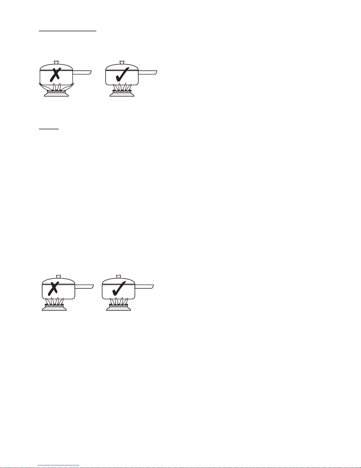
Adjust the burner flame so that it does
not extend over the pan base.
Pans
Use pans with a flat base of mini-
mum 120mm / 4 ins diameter and
maximum 250mm / 10 ins diameter which are stable in use.
Do not use double pans, rim based
pans, o ld mis shapen pans o r any
pan which is unstable when placed
on a flat surface.
Position pans over the centre of the
burners, resting on the pan supports. If positioned off centre, smaller pans may be unstable.
Do not let pans overhang the con -
trol knobs, as this may overheat and
damage them.
Always use pa ns whi ch a re larg e
enough to pre vent spillage, especially for deep frying.
Turn pan handles to a safe position,
so they are out of reach of children,
not overhanging the appliance, and
cannot be caught accidentally.
Do not use griddle plates on this
appliance, as this may be hazardous.
Material and size of pan, as well as
quantity and type of food to be
cooked, can affect cooking times.
Commercial simmering aids should
not be used as they create excessive
temperatures that c an damage the
surface and may cause a hazard.
Page 7

Pan supports
Always make sure the pan supports
are replaced correctly, located in the
hob spillage well, and that all rubber
feet are in place, to prevent instability.
The hob must only be operated when
both pan supports are correctl y positioned.
To save gas
• Always position pans centrally
over the burner.
• Use the size of pan most suited to
the size of the burner - ie; larger
pans on the rear burners, smaller
pans on the front burners.
• Adjust the flames so that they do
not lick up the sides of the pan.
• Put lids on saucepans and only
heat the amount of liquid you
need.
• When liquids boil, reduce the control setting to maintain a simmer.
• Consider the use of a pressure
cooker for the cooking of a complete meal.
• Potatoes and vegetables will cook
quicker if chopped into saller
pieces.
Note
Extra care should be taken when cooking food in salted water. Some foods
are corrosive - eg; vinegar, fruit juices
and especially salt
- they can mark or
damage stainless steel if they a re left
on the surface. Turn off and wipe any
spillage immediately, taking care to
avoid skin contact with any hot surface
or spillage.
Page 8
Care & Cleaning
Caution: Any cleaning agent
used incorrectly may damage
the hob.
Always let the hob cool before
cleaning.
Some cooking operations generate a
considerable amount of grease. This,
combined with spillage, can become a
hazard if allowed to accumulate on
the hob through lack of cleaning. In
extreme cases this may amount to misuse of the appliance & could invalidate your guarantee.
Do not use caustic, corrosive or abrasive cleaning products, coarse wire
wool or any hard implements, as they
will damage the surfaces.
All parts of the hob can be safely
cleaned with a cloth wrung out in hot
soapy water.
Burner caps and heads
Important: Allow burners to cool
before cleaning.
Caution: Hotplate burners can be
damaged by soaking, automatic dishwashers (or dishwasher powders / liquids), caustic pastes, hard implements,
coarse wire wool, and abrasive cleaning pastes.
Clean with a moist soapy pad.
For the burners to work safely, the slots
in the burner h ead where the flames
burn need to be kept clear of deposit.
Clean with a nylon brush, rinse, & dry
thoroughly.
Any brownish coloured marks o n the
burners are carbon deposits or fat stains,
which can be removed by gently rubbing with a soapy pad.
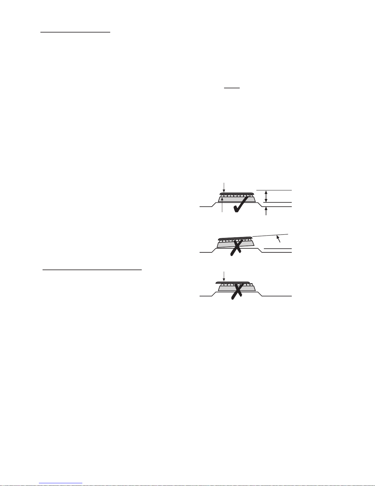
Important: The berner caps and
heads must
be repositioned correctly
so that they sit squarely onto the hob
as shown below.
This is particularly important with stainless s teel models a s f ailure to reposition the caps correctly may result in
discolouration of the stainless steel
around the burners.
incorrect
burner cap not central
incorrect
angled
correct
parallel
burner cap
burner head
Page 9

Control knobs
Only use hot soapy water.
When cleaning the fascia area, care
must be taken on symbols / markings.
Control knobs can be removed for
cleaning, but take care to ensure that
they are repositioned correctly after
cleaning.
Vitreous enamel surfaces
HOB SPILLAGE WELL (enamel hobs) , PAN
SUPPORTS
(if fitted)
Use a mild cream cleaner .
Stainless Steel hob
Only use a clean cloth wrung out in
hot soapy water, and dry with a soft
cloth.
Stubborn marks can be removed using
“Luneta”. We recommend that you
clean the whole of th e stainless steel
area to maintain a uniform finish.
Supplies can be purchased from the
Customer Care Centre.
Do not use undiluted bleach or any
products containing chlorides as they
can permanently damage the steel.
Extra care should be taken when cooking food in salted water. Some foods
are corrosive - eg; vinegar, fruit juices
and especially salt
- they can mark or
damage stainless steel if they are left
on the surface. Turn off and wipe any
spillage imme diately, taki ng care to
avoid skin contact with any hot surface
or spillage.
Sharp objects can mark the surface of
stainless steel, but marks will become
less noticeable with time.
To maintain the finish of stainless steel,
or to remove any greasy marks, wipe
the stainless steel surface sparingly
with a minimum
amount of Baby Oil
and kitchen paper. Do not use cooking oils, as these may contain salt,
which can damage the stainless steel
surface.
Please note: Do not steam clean any
parts of the hob.
Cast iron pansupports
(if fitted)
After cooking allow the pansupports to cool completely
before attempting to remove or
clean.
Before cleaning, remove any excess
fat with kitchen paper.
The pan supports can be cleaned with
hot soapy water and a nylon brush. If
any food residue is left on them leave
them to soak for a few minutes
in hot
soapy water before attempting to
clean it. Do n ot
use caustic pastes,
abrasive cleaning powders, coarse
wire wool or any hard implements, as
they will damage the surface.
Do not clean in a dishwasher.
Page 10

INSTALLATION INSTRUCTIONS - GAS PRODUCTS
Before you start: Please read the
instructions. Planning your installation will
save you time and effort.
Prior to installation, ensure that the local
distribution conditions (nature of the gas
and gas pressure) and the adjustment
of the appliance are compatible. The
adjustment conditions are stated on the
data badge.
This appliance is not connected to a
combustion evacuation device. It shall be
installed and connected in accordance
with current installation regulation.
Particular attention shall be given to
the relevant requirements regarding
ventilation.
The information below is crucial to
installing this appliance correctly and
safely.
Failure to install appliances correctly is
dangerous and could lead to prosecution.
Ventilation
Requirements
Ventilation must be as specified by
AS 5601 Installation code. The room
conatining the appliance should have an
air supply.
An appliance should be installed in a
location for complete combustion of gas,
proper flueing and to maintain ambient
temperature of the immediate surrounding
at safe limits, under normal conditions.
Failure to install appliances correctly is
dangerous and could lead to prosecution.
WARNI
NG - This appliance is unsuitable for
use in a marine environment.
If the appliance is placed on a base,
measures have to be taken to prevent it
slipping from the base.
Caution: The use of gas cooking appliance
results in the production of heat, moisure
and products of combustion in the room
in which it was installed. Ensure that
the kitchen is well ventilated especially
when the appliance is in use: keep
natural ventilation holes open or install a
mechanical ventilation device (mechanical
extractor hood).
Gas Safety (Installation & Use)
Regulations
This appliance must by an authorised
person in accordance with the
Australian Gas Installation Standard
AS5601 the manufacturers installation
instructions, local gas fitting
regulations, and any other relevant
statutory regulations.
Particular attention should be given
to relevant requirements regarding
ventilation.
Page 11

-
Installation
This appliance must be installed in
accordance with the regulations in
force, and only i n a well ventilated
space. Read the instructions before
using or installing this appliance.
This appliance will be factory set for
use on either natural gas only, or LPG
only. If the appliance requires conversion from natural gas to LPG, then the
conversion kit, part number 0130145
00, can be ordered from the Customer
Care Centre helpline given at the back
of this book.
Regulations & Standards
Prior to installation, ensure that the local
distribution condition (nature of the gas
and gas pressure) and adjustment of
the appliance are compatible.
The a djustment conditions for this
appliance are stated on the data
badge.
This appliance is not connected to a
combustion products evacuation device.
It shall be installed and connected in
accordance with current installation
regulations. Particular attention shall
be given to the relevant requirements
regarding ventilation.
The appliance must be installed, converted to LPG ( where necessary) and
serviced by a competent person to
ensure that the installation is in accordance with "The Gas Safety
(Installation & Use) Regulations”, & the
“The Gas Safe ty (In stallation & U se)
(Amendment) Regulations ”.
Failure to comply with these
Regulations is a criminal
offence.
Where regulations or standards have
been revised since this handbook was
printed, always use the latest edition.
All gas installation, servicing and
repair work must be in accordance
with local standards and regulations.
Page 12
Clearances & dimensions
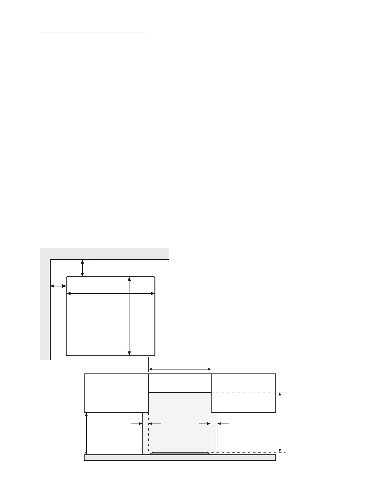
The room should have good light and
ventilation but be free from draughts.
The worktop should be at least
600mm deep, & 30mm thick to
enable the cutout to be made to the
dimensions shown below.
A minimum distance of 40mm should
be maintained between the hob and
rear wall / combustible surface.
A minimum distance of 78mm should
be maintained between the hob and
any side walls / combustible surface.
Surfaces which are non-combustible, or
are protected with suitable non-combustible material, may have reduced
clearances. Refer to New World for
guidance.
We recommend ceramic tiling for the
rear wall directly behind the hob.
No shelf or overhang of combustible
material should be closer than 650mm
above the hob.
Extractor or cooker hoods should only
be fitted above the hob in accordance
with the manufacturer’s instructions.
No combustible materials or flammable liquids should be stored below the
hob.
Sufficient length of cable should be
allowed so the hob can be removed
for servicing, but make sure it is routed
away from the underside of the hob &
does not get trapped during installation.
Important: Ensure that you route all
electrical cables and flexible tubing
well clear of any adjacent heat source
- eg; oven / grill.
600 hob - 600mm
700 hob - 700mm
40mm
40mm
worktop
420
mm
wall unit wall unit
This area must
be kept clear
of combustible
materials
650mm
above level of
pan supports
53mm min
side wall
rear wall
555mm
485
mm
cutout
600 - 53mm min
700 - 103mm min
Page 13
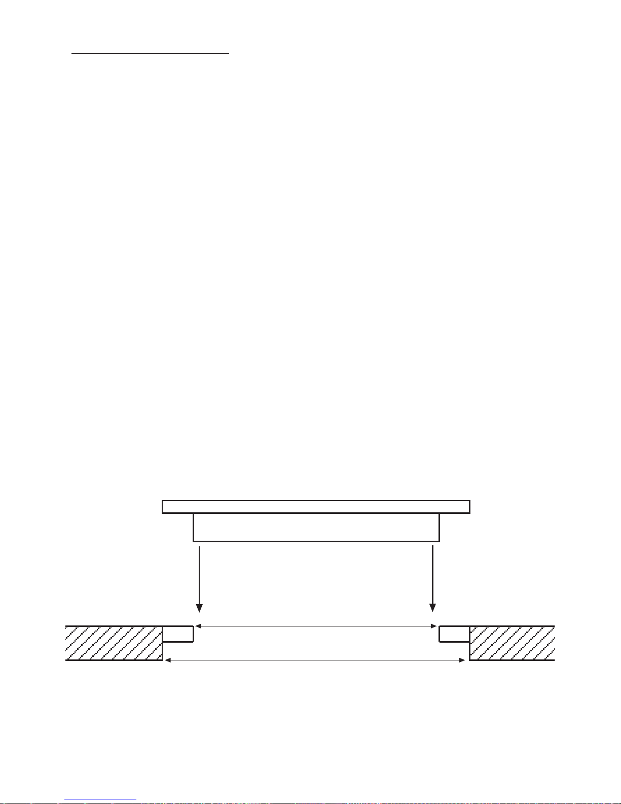
Base Tray
GDHA specified dimensions with batons
Existing dimension without batons
Important Information
It is important when installing front
control gas hobs, that the work top
cut out is the same as is quoted in
this installation manual. If the cut out
is too large, then batons must be fitted to the front, rear and sides - to
correct the discrepancy and ensure
the correct fit. Please ensure that if
batons are fitted they are level with
the top surface of the work top
Please ensure that the seal for the
hob has full contact with the work
top surface.
There are two ways to install
the clamps, depending on the thick-
ness of the work top, please measure
the thickness of your work top and
ensure that the correct method is
used. Both methods are detailed in
the installation manual.
Failure to follow these instructions can
lead to exessive force being applied
to the basetray, which results in the
clearence between the control knob
and the hob top pressing being
reduced. This can effect the operation of the gas control, and the ignition.
Page 14
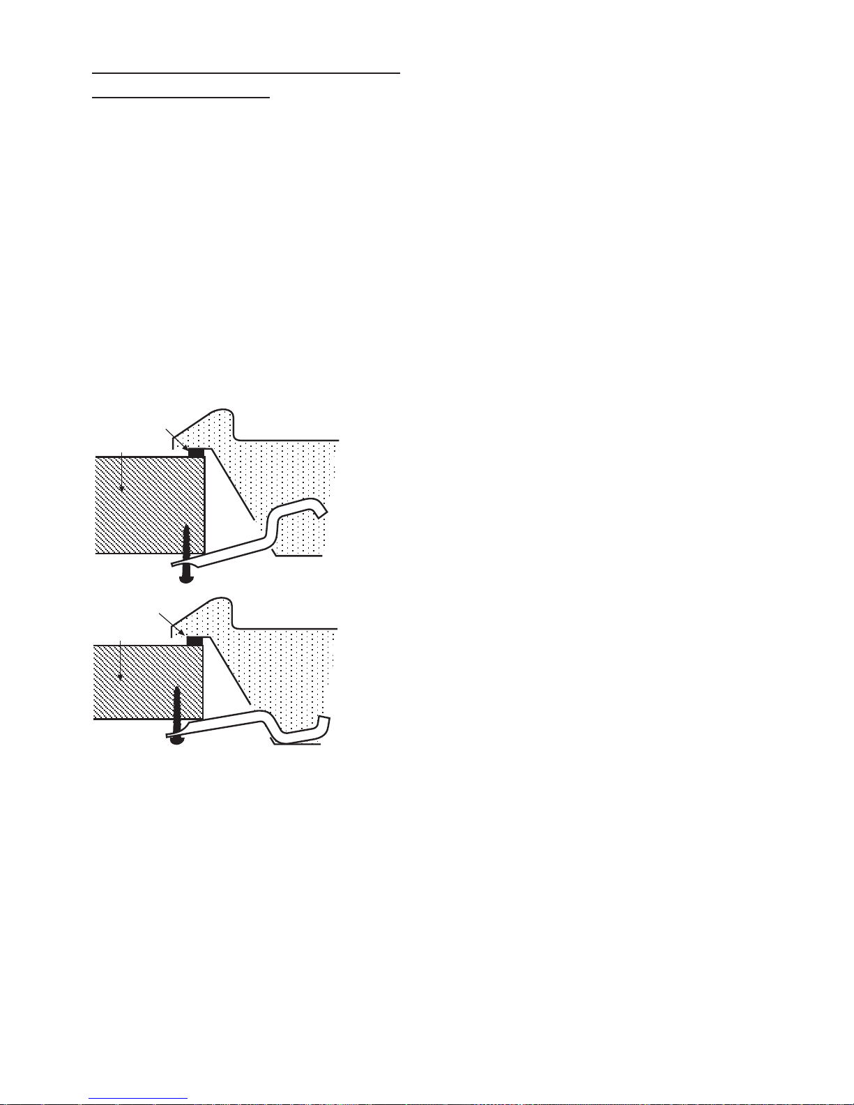
Fit the hob into the cutout &
secure to worktop
Place the hob into the cutout and
secure in place using the four brackets
and screws provided.
The brackets should be orientated to
suit the worktop thickness as shown,
then inserted into the four slots (two on
the front edge and two on the rear)
and screwed into the underside of the
worktop using the woodscrews provid-
ed.
The screws should be tightened just
sufficiently to secure the hob and pull
the top press ing fl ush with the worktop.
If the base of the hob is accessible
after installation then a partition must
be fitted 20mm below the base to prevent access.
seal
hob
40mm
worktop
seal
hob
30mm
worktop
Page 15

Alternative clamp positions
If the front and rear clamp positions
are problematic, alternative positions
can be used on the sides of the hob,
dependant on the particular installa-
tion.
These positions will require clearance
from any cabinet sides and may effect
how tightly the hob will meet the worktop.
Stone (Granite or equivalent)
worktops
Depending on the type of worktop
being used, there may or may not be
any backing material to screw the
clamp screws into.
1. If the worktop is a composite type
(backed with MDF or similar) there
may be enough backing to screw
directly into. This will depend on
the worktop thickness and backing
thickness and will have to be
assessed at the installation. In this
case, install the hob as for a standard worktop.
2. If there is insufficient backing mate-
rial to screw into, or if the worktop
is completely solid in const ruction,
then it will be necessary to glue a
strip of wood, MDF, fibre board or
similar to the underside of the worktop, along the front and rear edges
of the cutout. Use a strong, proprietary adhesive to bond these strips
and allow to cure before atte mpt-
ing to clamp the hob into position.
Page 16

Installation advice - cabinetry
Dealing with sides, cross- rails
a
nd back-panels in cabinetry
Depending on the cabinets, the worktop thickness and the hob positioning,
it is possible for the hob base, the
clamp brackets and/or the gas con nection to interfere with parts of the
cabinet. These can be dealt with as
follows:
Cabinet sides
If the hob i s to be i nstalled across the
top of two cabinet housing units, then
the base of the hob may interfere with
the sides of these units. It will be necessary to cu t away the top of the unit
sides locally to clear the ho b, cl amp
brackets and/or gas connection.
Cross-Rails
1. Interference with hob base
If there are any cross-rails which
obstruct the hob base by running
across the worktop cutout, they can
simply be removed or locally cutaway to allow the hob to be
installed, depending on the particular installation. Any modifications
must ensure that the strength of the
cabinet is maintained.
2. Interference with clamp brackets
If the re are any cross-rails which
prevent the clamps from being
positioned on the front or rear
edges of the hob, then they can be
removed or locally cut-away
around the brackets to allow the
brackets to be installed.
Any modifications must ensure that
the strength of the cabinet is maintained.
Back-panel
1. Interference with clamp brackets
If the cabinet has a back-panel
which prevents the clamps from
being positioned on the rear edge
of the hob, then this panel can be
completely removed or locally cutaway to allow the brackets to be
installed.
2. Interference or restriction of gas
connection
If the cabinet has a back-panel
which interferes with the position
of the gas supply to the hob, then
the panel can be completely
removed or locally cut-away to
allow connection to the gas supply.
Page 17
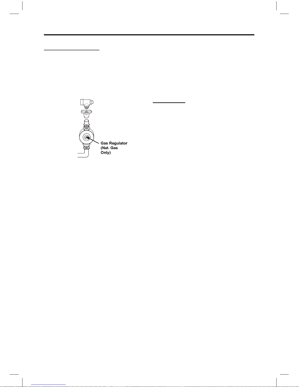
INSTALLATION INSTRUCTIONS - GAS PRODUCTS
Connect to the gas supply
Means of isolation shall be provided at the
shut off point by either an approved quick
connect device or a Type 1 manual shut
off valve. The outlet of the quick connect
device shall be at, or below, the horizontal
position.
Connection to the gas supply should be
made using the Aquaknect AS/NZS 1869
class B hose assembly with an internal
diameter of not less than 10mm and
regulator (regulator for use with natural
gas)
NOTE: Maximum length of hose 900mm.
The temperature rise of the areas at the
rear of the cooker that are likely to come
into contact with the flexible hose do not
exceed 70˙C.
The inlet to the cooker is ½” BSP internal
situated at the rear right corner. Fit the
bayonet connection. This should be
located so as to ensure that the flexible
connector hose does not kink.
Under no circumstances should the fle
xible
connector be allowed to come into contact with
the vertical oven flue tubes on the rear of the
appliance.
Use a 900mm - 1125mm length of
flexible connector.
Ensure that all pipework is of the correct
rating for both size and temperature.
After installation, mak
e sure all connections
are gas sound.
Commissioning
Burner aeration
All burners have fixed aeration and no
adjustment is possible.
Pressure setting
Natural Gas @ 1.00kP
a
Propane Gas @ 2.75kPa
Pressure test point
Use a hob injector
.
Connect to the electricity supply
Unless this appliance is supplied with a fitted plug,
it must be connected by a competent person, using
fixed wiring via a double pole switched fused spur outlet,
with a contact separation of 3mm at all poles.
Connect the mains lead wires to the terminals:
The blue wire must be connected to the terminal marked
N(Neutral) LOAD or coloured black.
The brown wire must be connected to the terminal marked
L(Live) LOAD or coloured red.
The green/yellow coloured wire must be connected to the
terminal marked E(Earth) or coloured green.
Warning: this appliance must be earthed.
The fused spur must be accessible after installation.
If the supply cord is damaged, obtain a special cord from
the Customer Care Helpline, which must be fitted by
a qualified person.
Hob burner - Turn the control knob to the
FULL ON position, wait a second before
pressing the ignition switch or holding a
lighted match or taper to the burner. Hold
the control knob in for 15 seconds. Do not
hold the control knob in for longer that 15
seconds. If the burner fails to light within
this time, release the control knob and
wait one minute before attempting further
ignition.
Page 18

Troubleshooting
Before you call Customer Care, please
check the following points:
Burner fails to ignite:
• Check the electricity supply is on.
• Check the fuse.
There is a spark t o t he bu rner
but it fails to ignite:
• Check that the flame holes in the
flame spreader are clear of water
or deposits.
• Check that the gas supply is turned
on.
Smell of gas:
• Check that none of the controls
have inadvertently been turned
on. If all the controls are in the off
position, turn off the gas supply &
call Customer Care.
The burner flame appears
uneven:
• Check the burner is fitted correctly.
• Check the flame holes in the flame
spreader are clear of water or
deposits.
Page 19
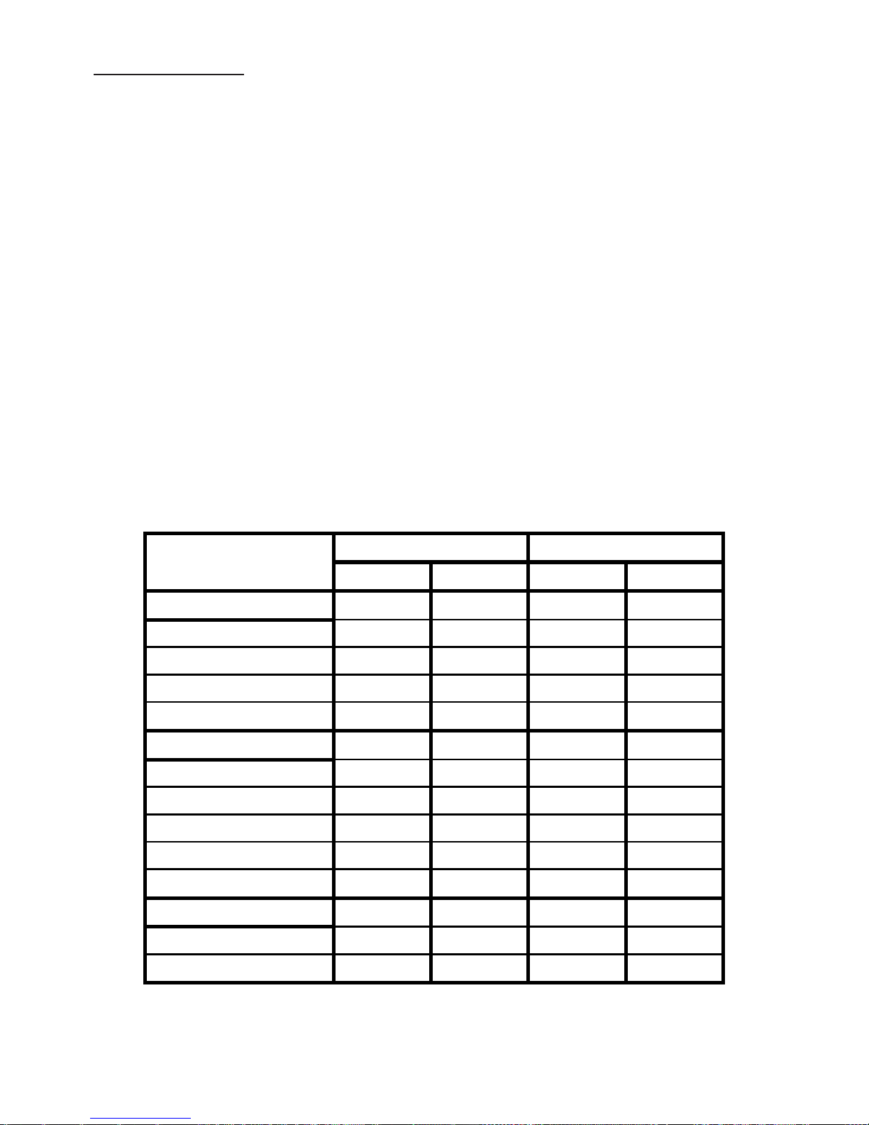
Technical Data
This in formation is
for the following appliances:
Belling Hobs GHU60/70 front & side
control - NG & LPG
Data badge Underside of the hob
base
Electrical supply
240V ~ 50Hz 1W
Ignition
Mains repetitive ignition.
Gas connectionThe inlet connection
is at the rear right-hand side -
ISO7 - Rp1/2” (1/2” BSP)
Gas pressure settings
Natural gas @ 1.0kPa
Propane gas @ 2.75kPa
Countries of destination
(AUS & NZ)
26.4
Injector
6.50
Total Heat Input
82Front RH
6.50
87
MJ/h
87
6.50
50
Wok
70
6.50
118
50
118
Front LH
6.50
Back RH
Burner
10.20
12.60
6.50
9.50
3.20
MJ/h
Back RH
25.70
138-72
GHU 60
Front RH
Natural Gas
12.60
39.0
GHU 70
GHU 70
118
142
3.20 3.20
9.50
LP Gas
118
6.50
Back LH
82
GHU 60
3.20
70
Front LH
Back LH
70
Injector
38.30
87-35
14210.20
6.50
70
Page 20

CONTACT US
Calling for a service
If you should experience any problems with your cooker please contact your retailer or
place of purchase.
Important note:
Service work is to be conducted by authorised persons only. It is also adviseable
that your cooker is checked regularly and maintained in good condition. An annual
maintenance is recommended.
Always check the instruction book before calling a service agent to make sure you have
not missed anything.
Glen Dimplex Australia Pty Ltd Customer Care:
Tel: Australia 1-300-556-816
New Zealand 09-274-8265
Before you contact a service agent, make sure that you have the following information to
hand:
Model Number
Serial Number
Date of Purchase
Postcode
Glen Dimplex Australia, Unit 2, 205 Abbotts Road, Dandenong,
South Victoria 3175, Australia
e-mail: [email protected]
web: www.glendimplex.com.au
Model Names: Belling GHU 60 - 70 GAS HOB 08 27521 00a 05.2010
Contact Us
Calling for a service
If you should experience any problems with your cooker please contact your retailer or
place of purchase.
Important note:
Service work is to be conducted by authorised persons only. It is also adviseable that
your cooker is checked regularly and maintained in good condition. An annual mainte-
nance is recommended.
Always check the instruction book before calling a service agent to make sure you have
not missed anything.
Glen Dimplex Australia Pty Ltd Cu stomer Care:
Tel: 1-300-556-816
Before you contact a service agent, make sure that you have the following information to
hand:
Model Number
Serial Number
Date of Purchase
Postcode
 Loading...