

Belling Cookcenter, Cookcenter 131, Cookcenter 133 Installation & User's Instructions

Belling
Cookcenter
Gas Cooker
Installation & User’s Instructions
Model No. 131 Natural gas
Model No. 133 LPG

Contents
Introduction.................................................................................................................3
Installation Instructions . .........................................................................................4-7
Space For Fixing. ...................................................................................................8
Connecting To The Gas Supply .................................................................................9
Electrical connection .................................................................................................10
Operational checks ....................................................................................................11
For Y our Safety Always ............................................................................................12
For Y our Safety Never ...............................................................................................13
Know Your Cooker ..............................................................................................14
Automatic Cooking Hints ........................................................................................15
Know Your Timer ................................................................................................16-22
Hotplate ......................................................................................................................23
Griddle & Fitting the Griddle Handles ..................................................................24
W arming zone ............................................................................................................25
Conventional Oven ............................................................................................26
Grill ..............................................................................................................................27
Fan Oven ................................................................................................................28-30
Cooking Charts For Main Ovens .................................................................. .....31-32
The ‘E’ Setting . .........................................................................................................33
Slow Cook/Warming Oven........................................................................................34
Care And Cleaning ........................................................................................35-36
Something Wrong? ..................................................................................................37
Spares And Service ...................................................................................... Back cover
2

Thank you for purchasing a new Belling Cookcenter. Its stylish and practical
design will enhance your kitchen and make cooking a pleasure. It features a
Fan oven, a conventional oven, a slow cook / warming oven, a separate grill
and a six burner hob with a warming area and removable griddle plate. There
is also a clock / timer with a minute minder and automatic oven switch on and
off.
If you have any problems with installing, operating, or cooking with your
Belling cooker, please check through these instructions thoroughly to make
sure that you have not missed anything. If you still need help then please
contact (including a daytime telephone number if possible):
Consumer Relations Department,
Belling Appliances Ltd.,
Talbot Road,
Mexborough,
South Yorkshire,
S64 8AJ
Belling helpline Tel: 01709 579902.
Please quote the cooker model and serial number with all enquiries. The serial
number can be found on the left hand side of the oven frame.
WARNING! Fo r y o u r o w n s afety, make sure that these instructions on
installation, use and maintenance are followed.
W e advise you to keep these instructions in a safe place for future reference.
If you sell or transfer ownership of this product, please pass on these
instructions to the new owner.
After unpacking your cooker, make sure that you remove all the packing from
the oven and grill and any stickers from the oven/grill door and the hob.
Getting help
Unpacking
3
Your Belling
Cooker
Introduction

4
Installation Instructions
Prior to installation, ensure that the local distribution conditions (nature of the
gas and gas pressure) and the adjustment conditions are compatible. The
adjustment conditions for this appliance are stated on the data badge which is
fitted on the rear panel.
This appliance is not designed to be connected to a combustion products
evacuation device. It must be installed and connected in accordance with
current installation regulations. Particular attention should be given to the
relevant requirements regarding ventilation.
Model number: 131
Category I2H(GB, IE)
This model is set to burn NATURAL GAS (G20) at 20mbar ONLY and cannot be
used on any other gas.
Model number: 133
Category I3+(GB, IE)
This model is set to burn BUTANE (G30) at 28-30mbar and PROPANE (G31) at
37mbar .
Gas safety (installation and use regulations)
It is the law that all gas appliances are installed by competent persons in
accordance with the current edition of the above regulations. It is in your
interest and that of safety to ensure compliance with the law.
In the UK, CORGI registered installers work to safe standards of practice.
The cooker must also be installed in accordance with BS 6172:
Failure to install the cooker correctly could invalidate the warranty liability
claims and could lead to prosecution.
Location
The cooker may be located in a kitchen, kitchen/diner or a bed-sitting room,
but not in a room containing a bath or shower. The cooker must not be
installed in a bed-sitting room of less than 20m3.
LPG models shall not be installed in a room or internal space below ground
level, e.g. in a basement.
Provision for ventilation
The room containing the cooker should have an air supply in accordance with
BS 5440:Part 2:
The room must have an opening window or equivalent; some rooms may also
require a permanent vent. If the room has a volume between 5 and 10m3, it
will require an air vent of 50 cm2effective area unless it has a door which
opens directly to outside. If the room has a volume of less than 5m3, it will
require an air vent of 100 cm2effective area. If there are other fuel burning
appliances in the same room, BS 5440: Pa rt 2: should be consulted to determine
air vent requirements.
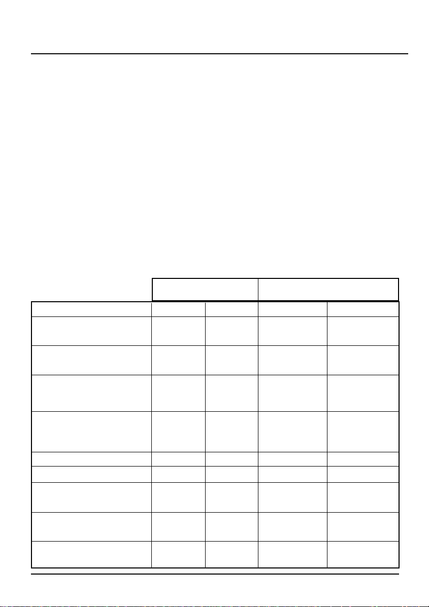
Electric Warming Zone
Hotplate
Electric
W arming/Slowcook Oven
MAIN OVEN
Conventional
3.8 kW
GRILL
72
2.8 kW
2.8 kW
0.22kw
0.25kw
MAIN OVEN - FA N
150
120
-
-
120
128
3.5 kW
HOTPLATE
Front middle (Wo k)
Installation Instructions
5
Technical data
Dimensions
Height 900 - 915mm
Width 1082mm
Depth 600mm (excluding door handles)
General
Gas connection Rp 1/2(1/2” BSP female)
Gas supply Natural gas models - G20 at 20 mbar
LPG models - Propane (G31) at 37 mbar and
Butane (G30) at 28-30 mbar
Pressure test point Grill injector
Gas rate adjustment None
Aeration adjustment None
Electrical connection Flexible cord fitted with a 3 pin 13 amp plug
230 - 240V a.c. 50Hz. 3A fuse.
HEAT INPUT
BURNER
Natural Gas Models LPG Models
INJECTOR
HEAT INPUT
INJECTOR
HOTPLATE
Rear left rapid
HOTPLATE
Front right & rear right
(auxiliary)
130
HOTPLATE
Front left & rear middle
(semi-rapid)
2.0 kW
1.0 kW
102
3.0 kW
2.5 kW
3.4 kW
95
2.5 kW
0.22kw
0.25kw
75
-
-
75
65
3.2 kW
82
1.8 kW
1.0 kW
50
2.8 kW
90
Installation Instructions
Unpack the components from inside the grill and oven: Check
that the following parts are present.
Grill pan and grid
Main oven shelves (4)
Main oven shelf heat shield
Griddle
Pan supports (3)
Meat pan
Literature
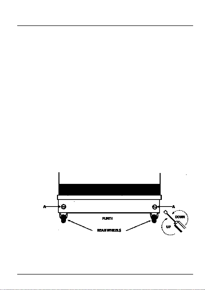
Two rear wheels and two front feet are fitted which can be adjusted
up or down to set the height (900mm - 915mm) and level the
cooker.
1. The rear wheels can be raised or lowered from the BACK of the
cooker by adjusting the levelling screws ‘A’ i n the plinth.
2. The front feet can be simply screwed in or out to lower or raise
the front of the cooker.
Some soft floor coverings may get damaged if the cooker is not
moved carefully.
6
Unpacking the
cooker
NOTE: This appliance should not be installed on a platform.
Levelling
Caution:
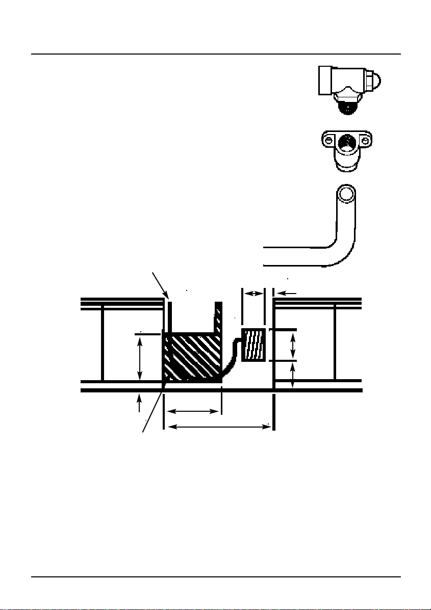
PENCIL LINE
PLINTH
BRACKET
W ALL
Installation Instructions
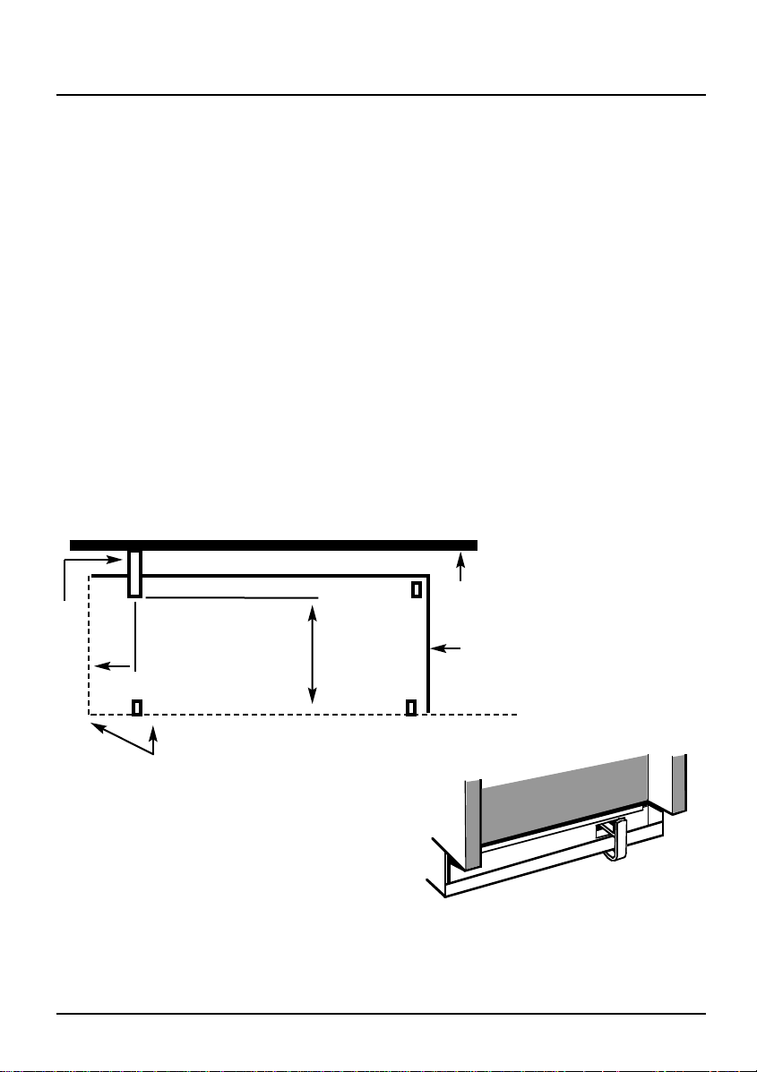
The cooker must be fitted with a stability device, firmly
secured to the fabric of the building. The back of the cooker
has a slot for engagement of a stability bracket, which can be
obtained, as an extra, from the cooker supplier. The leaflet
included with the bracket should be read in conjunction with
the following instructions.
Push cooker to its intended position.
Draw pencil lines on the floor in line with the front and
left side of the plinth.
Remove the cooker.
Position stability bracket so front edge is 410mm from
the front of the cooker and its centre is 92mm from
the left hand side - see diagram below.
Measure height from floor level to the bottom of the
slot in the back of the cooker. Add 3mm to the
dimension and assemble the stability bracket to that
height. (i.e. from floor level to the underside of the top
member).
Stability
bracket
7
92
mm
410mm
1085
400
8
Space For Fixing
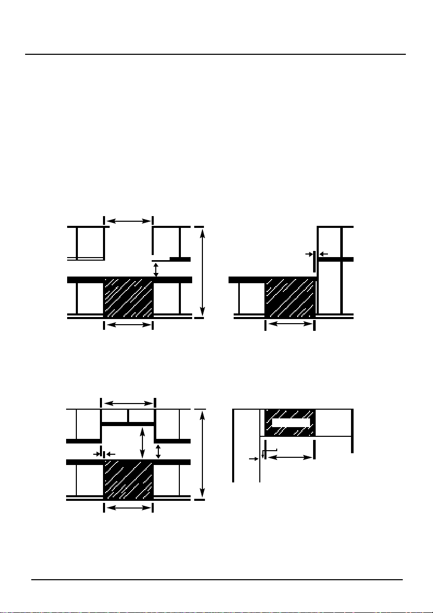
The cooker can be close fitted below hotplate level. This
requires a minimum distance of 1085mm between cupboard
units of hotplate height.
The wall behind the cooker between the hotplate and 450mm
above, and across the width of the cooker, must be an
incombustible material such as ceramic wall tiles.
Follow the diagrams below for guidance on fitting. Take note
of all dimensions.
If your appliance is to be fitted close to a corner ensure that
there is a clearance of 135mm minimum. This will enable you
to fully open the door and allow removal of oven shelves.
1085
1085
2050 min
Gap can be in filled
below hotplate level
65
1085
1085
794
25 min
400
min
2050 min
Cupboards
or wall
Appliance
Cupboar
d
135 min
Fig. 1
INSTALLATION WITH WALL
CUPBOARDS IN LINE WITH SIDES OF
APPLIANCE
Fig. 3
INSTALLATION ALONGSIDE TALL
CUPBOARDS OR SIDE WALL
Fig. 4
INSTALLATION CLOSE TO A CORNER
Fig. 2
INSTALLATION USING BRIDGING
CUPBOARDS
1200
Connecting to the Gas Supply
9
This area to be clear of pipework
and obstructions
450 250
80 470
1085
570
160
60
MAINS INLET ON
APPLIANCE
Connection to the cooker should be made with an approved appliance flexible connection
to BS 669. Hoses connected to the LPG models should be suitable for LPG and capable of
withstanding 50mbar pressure. A length of 0.9 to 1.25m is recommended. The length of
hose chosen should be such that when the cooker is in situ, the hose does not touch the
floor.
The temperature rise of areas at the rear of the cooker that are likely to come in contact
with the flexible hose do not exceed 70˚C.
After installation, check for soundness.
The supply pressure can be checked at the grill injector. Access to the injector is by first
removing the baffle at the front of the grill compartment and then the burner.
The cooker is designed to match the depth of
standard 600mm worktops. An adaptor backplate
should, therefore, be fitted within the 160 x
250mm shaded area shown, pointing towards the
left to allow the cooker to be pushed fully to the
wall. If a forward facing backplate is used, it must
be chased into the wall.
Electrical Connection
10
Connection to the electricity supply should be made via a properly earthed, readily
accessible wall socket which is adjacent to, and not more than 1.25m away from the
appliance and capable of electrical isolation.
Should this plug not fit the socket outlet in your home it should be cut off and replaced
with a suitable plug as outlined below.
Note: The removed plug cannot be used for any other appliance and should therefore
be properly disposed of and not left where children might find it and plug it into a
supply
socket – with the obvious consequent danger.
If the fitted plug is removed
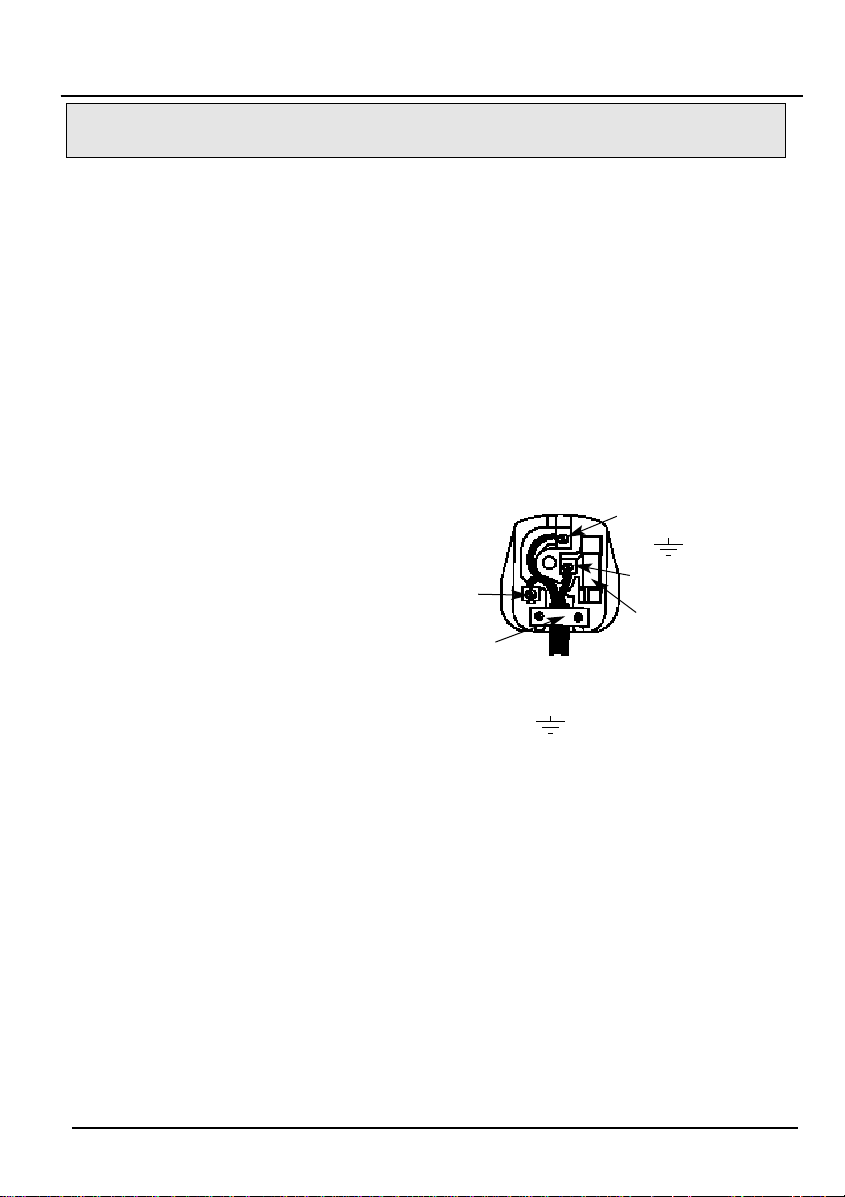
The flexible mains lead must be correctly connected as below to a three pin plug of not
less than 13 amp capacity. If a B.S. 1363 fused plug is used, it must be fitted with a 3
amp fuse which is approved to B.S. 1362.
Important: The wires in the mains lead fitted to this appliance
are coloured in
accordance with the following code:
GREEN AND YELLO W – EARTH
BLUE – NEUTRAL
BROWN – LIVE
As the colours of the wires in the mains lead of this appliance may not correspond with
the coloured markings identifying the terminals in your plug, proceed as follows:– The
wire which is coloured green and yellow must be connected to the terminal in the plug
which is marked with the letter E or by the earth symbol or coloured green or green
and yellow. The wire which is coloured blue must be connected to the terminal which is
marked with the N or coloured black. The wire which is coloured brown must be
connected to the
terminal which is marked with the letter L or coloured red. When wiring the plug,
ensure that all strands of wire are securely retained in each terminal. Do not forget to
tighten the mains lead clamp on the plug. As the appliance must be earthed, do not
use 2-pin
sockets outlets, if you are in doubt, consult a qualified electrician.
Should the mains lead ever require replacement, it is essential that this operation be
carried out by a qualified electrician and should only be replaced with a flexible cord of
the same size i.e. 0.75mm
2
cross sectional area.
If a moulded plug is fitted
In the event of replacing a fuse in the plug supplied a 3 amp ASTA approved fuse to
BS1362 must be fitted.
NOTE: The fuse cover must be refitted when changing the fuse. In the event of losing
the fuse cover the plug must not be used until a replacement fuse cover has been
obtained and fitted. A new fuse cover can be obtained from your local Electricity
Retailer. The colour of the correct replacement fuse cover is that of the coloured marks
or inserts in the base of the plug.
WARNING – THIS APPLIANCE MUST BE EARTHED.
CONNECT TO A 230-240V A.C. SUPPLY ONLY.
Green &
Yellow to
Earth
Brown to
Live
Blue to
Neutral
Cord Clamp
3 Amp
Fuse

11
Operational Checks
Fit the pan supports and remove any packaging.
With reference to the user’s instructions:
1. Check that the hotplate and grill burners ignite correctly and burn with a
steady flame. Check for a steady flame at the low (small flame symbol)
setting.
2. Check that with each main oven set to Mark 9, the burner ignites at a low
rate, and then increases to full rate within 60 seconds. Leave the oven full
on with the door closed for 10 minutes and then check that the flame
reduces when the control is turned to the E setting.
3. Check operation of timer and main oven lights.
Instruct the user on the operation of the cooker.

12
For Y our Safety
Please read the precautions below before using your
cooker.
ALW AYS make sure you understand the controls before using
the cooker.
ALW A YS check that all controls on the cooker are turned off
after use.
ALW AYS stand back when opening an oven door to allow
heat to disperse.
ALW A YS use dry, good quality oven gloves when removing
items from the ovens.
ALW AYS take care when removing items from the grill when
the main oven is on, as the contents may be hot.
ALW A YS keep the oven and grill doors closed when the
cooker is not in use.
ALW A YS place pans centrally over the hotplate burners and
position them so that the handles cannot
accidentally be caught or knocked or become
heated by other burners.
ALW A YS keep the cooker clean, as a build up of grease or fat
from cooking can cause a fire.
ALW A YS allow the cooker to cool before cleaning.
ALW AYS follow the basic principles of food handling and
hygiene to prevent the possibility of bacterial
growth.
ALW A YS keep ventilation slots clear of obstructions.
ALW A YS turn off the electricity supply before cleaning or
replacing the oven lamp.
ALW A YS refer servicing to CORGI registered appliance service
engineers.
A l W A YS ensure that the Griddle is fitted correctly to the pan
supports and that the fingers are located correctly
within the slots in the Griddle feet.
ALW AYS remove the Griddle handles during the cooking
period.
ALW A YS take care when fitting the Griddle handles NOT to
contact any of the hot surfaces of the Griddle or the
appliance.
ALW AYS remove any spillage from the surface of the lid
before opening.
ALW A YS allow the hob to cool before closing the lid.
Always..
 Loading...