

Page 1

Network your
computers and
share your ADSL
Internet access
ADSL Modem
with 802.11g
Wireless Router
Designed to Meet ADSL2+ Specification
User Manual
F5D7633au4A
Page 2

Table of Contents
1
1 Introduction . . . . . . . . . . . . . . . . . . . . . . . . . . . . . . . . . . . . . . . .1
Product Features . . . . . . . . . . . . . . . . . . . . . . . . . . . . . . . . . . .
Benefits of a Home Network . . . . . . . . . . . . . . . . . . . . . . . . . .
Advantages of a Belkin Wireless Network . . . . . . . . . . . . . . . .
2 Make Sure You Have the Following . . . . . . . . . . . . . . . . . . . . . . .
Package Contents . . . . . . . . . . . . . . . . . . . . . . . . . . . . . . . . . .
System Requirements . . . . . . . . . . . . . . . . . . . . . . . . . . . . . . .
Internet Connection Settings . . . . . . . . . . . . . . . . . . . . . . . . . .
3 Knowing your Router . . . . . . . . . . . . . . . . . . . . . . . . . . . . . . . . .
4 Connecting your Router . . . . . . . . . . . . . . . . . . . . . . . . . . . . . . .
Positioning your Router . . . . . . . . . . . . . . . . . . . . . . . . . . . . . .
Connecting your Computers . . . . . . . . . . . . . . . . . . . . . . . . . .
Connecting your ADSL Line . . . . . . . . . . . . . . . . . . . . . . . . . .10
Powering Up your Router. . . . . . . . . . . . . . . . . . . . . . . . . . . .12
5 Setting Up your Computers . . . . . . . . . . . . . . . . . . . . . . . . . . .
Manually Configuring Network Adapters . . . . . . . . . . . . . . . .13
Recommended Web Browser Settings. . . . . . . . . . . . . . . . . .19
6 Configuring your Router with the Setup Wizard . . . . . . . . . . .21
Running the Setup Wizard . . . . . . . . . . . . . . . . . . . . . . . . . . .21
Connecting to the Wireless LAN . . . . . . . . . . . . . . . . . . . . . 24
7 Manually Configuring Your Router . . . . . . . . . . . . . . . . . . . . . .
Understanding the Web-Based User Interface. . . . . . . . . . . .
Changing LAN Settings . . . . . . . . . . . . . . . . . . . . . . . . . . . . . 27
Internet WAN . . . . . . . . . . . . . . . . . . . . . . . . . . . . . . . . . . . . .30
Wireless . . . . . . . . . . . . . . . . . . . . . . . . . . . . . . . . . . . . . . . . .
Firewall. . . . . . . . . . . . . . . . . . . . . . . . . . . . . . . . . . . . . . . . . .54
Utilities . . . . . . . . . . . . . . . . . . . . . . . . . . . . . . . . . . . . . . . . . .
8 Troubleshooting . . . . . . . . . . . . . . . . . . . . . . . . . . . . . . . . . . . .
9 Technical Support Information . . . . . . . . . . . . . . . . . . . . . . . . .78
10 Appendixes . . . . . . . . . . . . . . . . . . . . . . . . . . . . . . . . . . . . . . .79
Appendix A: Glossary . . . . . . . . . . . . . . . . . . . . . . . . . . . . . .
Appendix B: Important Factors for Placement and Setup . . .85
Appendix C: Internet Connection Setting Table . . . . . . . . . . .88
11 Information . . . . . . . . . . . . . . . . . . . . . . . . . . . . . . . . . . . . . . .89
13
25
25
36
58
66
79
1
3
3
4
4
4
4
5
8
8
9
Page 3

1
Introduction
Thank yo u for purchasing th e Belkin AD SL Modem with W irel ess
802.11g Ro uter (the R ou ter). In mi nu tes you w il l be able t o share
your Int er net c on nection and n etwork your c omputers wi th your new
Router. Th e following i s a list of f eatures that ma ke your Rou te r an
ideal so lu tion for yo ur home or sm al l office networ k. Please b e su re t o
rea d through this Us er Manual c om pletely, and pay s pe cial atte nt io n to
Appendix B entitled “ Im portant F ac to rs for Pl ac ement and S et up”.
Product Features
Compatibility with Both PCs and Mac® Computers
The Router support s a variet y of netwo rk ing e nvironments includin g
Mac OS® 8 .x, 9 .x, X v1 0. x, Ap pleTalk®, Linux®, Windows® 9 5, 98 SE,
Me, NT®, 2000, and XP, a nd ot hers. You ne ed an Inte rnet browser
and a n etwork adapter that suppor ts TC P/ IP (t he st andard la nguage
of the Inter ne t) .
Front-Panel LED Display
Lighted LEDs on the fro nt of th e R ou te r i nd icate which functio ns
are in oper at ion. You’ ll kn ow at -a-glance whethe r you r Rou te r i s
connecte d to the Internet. This feature eliminates the need for
advanced soft wa re and statu s- monitoring procedures.
Web-Based Advanced User Interface
You ca n set up the Router’s advanced functi on s e as ily t hrou gh yo ur
web brow ser, without having to instal l add it ional software o nto t he
computer. The re are no di sk s t o ins ta ll or ke ep tr ac k o f and , bes t
of all, you can m ake c hanges and perform setup functi on s f rom any
computer on the network quic kl y a nd ea si ly.
Integrated 10/100 4-Port Switch
The Router has a built-in, 4-port netw or k s wi tch t o a ll ow yo ur wi re d
computer s to share printers , dat a and MP3 files , dig it al ph otos,
and much more . T he sw it ch fe atures au tomatic detectio n so it will
adjust to the speed of connected devic es . T he sw it ch wi ll tr ansfer
data between compu te rs an d t he In te rnet simul ta neously without
interrup ti ng or co ns uming res ourc es .
Integrated 802.11g Wireless Access Point
802.11g is an exciting new wireless techno lo gy th at ac hieves data
rates up to 54Mbps, nearly five times faste r tha n 802 .1 1b.
sec t ion
1
2
3
4
5
6
7
8
9
10
11
12
1
Page 4

Introduction
3
Turbo Mode
Belkin’s rout er su pp orts Frame Bursting mode.
Selectin g “Fr am e B ur sting” will re sult in al l d ev ices capable of
Frame Burstin g to funct io n i n fra me bu rs ting mode, and all c lients
not capable to operate in normal 802.1 1g mo de s. Fr ame B ursting
mode supports both Fram e Bur st ing e nabled devices and non Frame
Bursting enab le d d ev ices simultaneou sl y. Frame Bursti ng mo de is
based on the unrel eased 802.11e speci fi cation.
Built-In Dynamic Host Configuration Protocol (DHCP)
Built-In Dyna mi c H os t C on figuration Protocol (DHCP ) on- bo ard mak es
for the easiest possibl e con ne ction of a ne tw ork. The D HCP s erver
will assign IP addresses to each computer autom at ically so there is no
need for a c omplicated netwo rk ing s etup.
NAT IP Address Sharing
Your R ou ter e mploys Network Address Transla ti on (N AT) t o s ha re the
single IP address assigned to you by y our I ntern et Se rv ice P ro vi der
while saving the cost of adding additi on al IP ad dres se s t o you r
Intern et se rvice account.
SPI Firewall
Your R ou ter i s e qu ipped with a fi re wa ll th at wi ll prot ec t y ou r n et work
fro m a wide arra y o f com mo n h ac ke r a tt acks including IP Spoofi ng ,
Land Attack, Ping of Death (PoD), Deni al of Serv ic e ( Do S), I P w it h z ero
length, Smurf Atta ck , T CP Nu ll Sc an , S YN fl oo d, UD P f lo oding, Tear
Dro p A tt ack, ICMP defect, RIP defect, and fragm en t f lo oding.
MAC Address Filtering
For added security, you can set up a list of MAC addresses (unique client
identifiers) that are allowed access to your network. Every computer has its
own MAC address. Simply enter these MAC addresses into a list using the
web-based user interface and you can control access to your network.
Universal Plug-and-Play (UPnP) Compatibility
UPnP (Univers al Pl ug -and-Play) is a technology that offers seamle ss
operatio n of voice mess ag ing, video messaging, game s, an d oth er
applicat io ns th at are UPnP- co mpliant.
Support for VPN Pass-Through
If you connect to your off ic e n et work from ho me us in g a VPN
connecti on , y ou r R ou ter w ill a llow your VPN-equippe d com pu ter t o
pass through the R outer and to yo ur offi ce ne tw ork.
Page 5

32
Introduction
Benefits of a Home Network
By following our simple setu p ins tr uctions, you will be able to u se
your Belkin home networ k to:
• Share on e h ig h-speed Internet connection with all the compute rs
in your home
• Share reso urce s, su ch as file s, an d hard drives among all the
connecte d com pu ters in yo ur ho me
• Share a sin gl e p ri nter with the e ntire f am ily
• Share do cuments, music , vid eo , a nd di gi tal p icture s
• Store, ret ri eve, and c opy f iles from on e com pu ter t o a no ther
• Simultan eo usly play games online, check Internet email,
and chat
sec t ion
1
2
3
4
5
6
7
Advantages of a Belkin Wireless Network
Mobility – you’ll no longer need a dedicated “computer room”— now you
can work on a networked laptop or desktop computer anywhere within
your wireless range
Easy installation –
Flexibility – set up and access printers, computers, and other
networking devices from anywhere in your home
Easy Expansion – the wide range of Belkin networking products let
you expand your network to include devices such as printers and
gaming consoles
No cabling required – you can spare the expense and hassle of
retrofitting Ethernet cabling throughout the home or office
Widespread industry acceptance – choose from a wide range of
interoperable networking products
Belkin’s Easy Installation Wizard makes setup simple
3
8
9
10
11
12
Page 6

5
Make Sure You Have the Following
Package Contents
• ADSL Modem with 802.11g Wireless Router
• RJ11 Telephone Cord
• RJ45 Ethernet Networking Cable
• Power Adapter
• User Manual CD
System Requirements
• An active ADSL service with a telephone wall jack for connecting
the Router
• At least one computer with a Network Interface Card (NIC) and Internet
browser installed and correctly configured
• TCP/IP networking protocol installed on each computer connected to
the Router
• No other DHCP server on your local network assigning IP addresses to
computers and devices
Internet Connection Settings
Please collect the following information from your Internet Service Provider
(ISP) before setting up the ADSL Modem Wireless G Router.
• Internet connection protocol: _________ (PPPoE, PPPoA, Dynamic IP,
Static IP)
• Multiplexing method or Encapsulation: __________ (LLC or VC MUX)
• Virtual circuit: VPI (Virtual Path Identifier) __________
(a number between 0 and 255)
• VCI (Virtual Channel Identifier) __________
(a number between 1 and 65535)
• For PPPoE and PPPoA users: ADSL account user name _____________
and password _______________
• For static IP users: IP Address ___ . ___ . ___
Subnet Mask ___ . ___ . ___
Default Gateway Server ___ . ___ . ___ .
• IP address for Domain Name Server ___ . ___ . ___ . ___ (If given by
your ISP)
Note: See Appendix C in this User Manual for some common DSL
Internet setting parameters. If you are not sure, please contact your ISP.
Page 7
54
Knowing your Router
The Router is designed to be placed on a d esktop. All of the c ables
exit fro m t he rear of the Router for better org anization and utility. The
LED indicator s are easily visibl e on the front of th e R ou ter t o p rovi de
you with informati on ab ou t n et work activity and status.
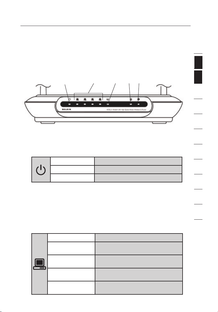
Front Panel
1. Power LED
When you apply power to the Router or res ta rt it , a sh or t p er io d
of time elapses while the Router boots up. When the Router has
complete ly bo ot ed up , t he Po we r L ED be co mes a SO LI D l ig ht,
indicati ng th e Rou te r i s ready for use.
2. LAN Status LED
These LAN Status LEDs are la beled 1–4 and c orre spond to t he
numbered ports on the rea r of the Router. Whe n a comput er is
pro perly connecte d to one of the LAN p orts on th e rear of the
Router, the LED will light. Solid GREE N mea ns a compu te r o r a
network- en abled device is connected. When info rm ation is b eing
sent over the port, the LED blinks rapidly. ORANGE indicates a
10Base-T conn ec tion.
(1) (4) (5)(3)(2)
OFF Router is OFF
Gre en Router is ON
Red Router failed to start
OFF Your d ev ice i s c on nected
Orange Ethern et li nk is up an d 10B as e- T
Orange - blinking When 10Base-T devi ce tr an smitting
Gre en Ethern et li nk is up an d
Gre en - bli nk ing When 100Base -T de vi ce
device connec te d
or rec ei ving data
100Base- T con ne cted
transmit ti ng or receiv in g d at a
1
2
sec t ion
3
4
5
6
7
8
9
10
11
12
5
Page 8

Knowing your Router
7
3. WLAN Status LED
The WLAN Status LED is solid GREEN when you enable the
wireless LAN function. It flashe s whe n the Rout er is tran sm itting
or rec ei ving data wire lessly.
OFF WLAN is off
Gre en WLAN is up a nd co nnected
Gre en - bli nk ing Whe n tra ns mi tted or rece iv ing d ata
4. ADSL LED
The ADSL LED flashes GREEN during nego ti ation with your ISP.
It stays GREEN when the Router is connected properly to your
ADSL service.
OFF no ADSL connection
Gre en ADSL link is up a nd co nnected
Gre en -
5. Internet LED
The Inter ne t L ED sh ow s y ou wh en th e R ou ter i s c on nected to
the Inter ne t. Wh en th e L ED is OF F, the Router is NOT connected
to the Inter ne t. Wh en th e L ED is soli d GRE EN , t he Ro ut er is
connecte d to the Internet. When the LED is b linking, the Router
is transmitti ng or receivin g dat a from the Intern et.
blinking negotiat in g c on nection
OFF No Intern et co nn ection
Gre en Connecte d to the Internet
Gre en -
Red Failed to get IP
blinking When transmit ti ng or receiv in g d at a
Page 9
76
Knowing your Router
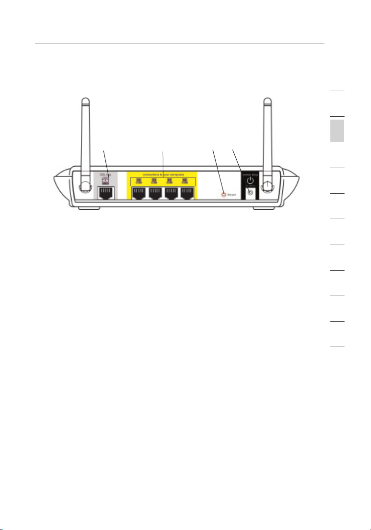
Back Panel
(6)
6. DSL Line
This port is for connection to your ADSL line. Connec t you r ADS L
line to this port.
7. Ethernet Ports
The Ether ne t p or ts are RJ45, 10/1 00 au to -negotiatio n. Th e por ts
are la be led 1 th roug h 4. These port s cor resp on d t o the numb ered
LEDs on the fron t o f the Rout er. C on ne ct your network-ena bl ed
computer s or any networ ki ng de vices to o ne of th es e p or ts.
8. Reset Button
The “Reset” button is used in rare c as es wh en th e R ou ter m ay
function improper ly. Resetting the Router will restore the R outer’s
normal operat io n w hi le ma intaining the programmed setti ng s. You
can also re st ore the fact or y d ef ault settings by using the Reset
button. Use the re store o pt ion i n i ns tances where y ou ma y h av e
forgo tten your custom password.
a. Resetting the Router
b. Restoring the Factory Defaults
9. Power Plug
Connect the includ ed 15 V DC power supp ly to this inle t.
Using the wro ng ty pe of po we r a da pter may c ause damage
to your Router.
Push and hold the Reset button for one second then re lease
it. When the Power/Read y lig ht be co mes s olid again, the
res et is co mp lete.
Pre ss an d h ol d t he Re se t b ut ton f or fi ve se conds then
rel ease it. W hen t he Po wer/Ready ligh t bec om es so lid a gain,
the re st ore is compl et e.
(7) (8) (9)
1
2
sec t ion
3
4
5
6
7
8
9
10
11
12
7
Page 10

Connecting your Router
9
Positioning your Router
Your w irel es s c on nection will be stron ger t he cl oser your computer
is to y our R outer. Typi cal i ndoor operatin g ran ge fo r you r wireless
devices is between 100 and 200 feet. In the same way, you r wireless
connecti on an d per fo rmance will degrade somewh at as the dista nc e
between your Route r con ne cted devices increases. This may or may
not be noticeable to you. As you move further from yo ur Ro uter,
connecti on sp ee d m ay de crea se . F ac tors that can w eaken signals
simply by getting in the way of your network’s ra dio w aves are metal
applianc es , o r obs tr uctions, and walls. Please see “Appe nd ix B:
Importan t Fac to rs fo r P la cement and Setup” in this User Manual for
more g ui delines.
If you have concern s a bo ut yo ur ne tw ork’s perf or mance that might be
rel ated to ra nge o r o bs truction facto rs , t ry mo vi ng th e c om puter to
a position between five and 10 feet from th e R ou ter, in orde r to see
if distance is the prob lem. If di ff ic ulties persist even at close range,
please see the Troubleshoot in g s ec tion for s olutions.
Page 11

98
Connecting your Router
Connecting your Computers
1. Pow er off your compu te rs an d n et working equipmen t.
2. Con nect your computer to one of the YE LLOW RJ45 ports on t he
rea r o f the Rout er la be led “ connectio ns to your comp ut ers” by
using an Ether ne t n et working cable (one Ether net network cable
is supplied).
1
2
3
sec t ion
4
5
6
7
8
9
10
11
12
9
Page 12

Connecting your Router
11
Connecting your ADSL Line
Connecti on fo r the Rout er to the ADSL line varie s by count ry an d
reg ion. Typi cally it i nvolves a microf ilter or a mi crof il ter w ith b uilt-in
splitter to allow simul ta neous use of AD SL se rvice and telephone
service on the same telephon e lin e. Pl ea se read the follo wi ng st eps
carefully and select appropriate metho d.
1. If your telephone servi ce an d ADS L ser vi ce are on the same
telephon e lin e, AD SL mi crof il ters are neede d for each tele ph one
and device, such as answerin g mac hi ne, f ax ma chine, and caller
ID display. Ad ditional splitte rs ma y be used to separat e tel ep hone
lines for telephon e and the Route r.
Note: Do not connect the ADSL microfilter betwe en th e wal l jac k
and the Router—thi s wil l prevent ADSL serv ic e f rom reaching
the modem.
2. If y ou r t el ep hone service and ADSL service are on th e s am e
telephon e lin e and you are u sing an AD SL mi crof ilter with built-in
splitter, con ne ct th e s pl itter to t he te lephone wall jack providing
ADSL service. Then , con ne ct th e t el ephone cord from the ADSL
microfilter RJ11 port gener al ly la beled “DSL” to the g ray R J11
port labeled “DSL line” on the back of your Router. Connec t
telephon y dev ic e t o the othe r por t on the ADSL splitt er co mm only
labeled “Phon e” . A n add it ional ADSL microfilter is needed for
another telep ho ne an d d ev ice o n t he sa me li ne .
Page 13

1110
Connecting your Router
Note: One RJ11 telephon e cord is supplied. When inse rt ing a n
RJ11 plug, be sure th e t ab on the plug click s int o pos it io n t o
ensure t hat i t i s p roperl y sea te d.
1
2
3
sec t ion
4
5
6
7
8
9
3. If y ou ha ve a dedic at ed AD SL se rvice telephone line with an RJ11
wall jack, simply conne ct a telep ho ne co rd from the wall jack to
the gray RJ11 port labeled “DSL line” on the back of
your Router.
4. If y ou ha ve an RJ45 wall jack for your ADSL servi ce , c on nect an
RJ45-to- RJ 11 co nverter to the wa ll ja ck. T hen c onnect one end of
a telephone cord t o t he co nv erter and the o ther end t o t he gr ay
RJ11 port labeled “DSL line” on the back of your Router.
11
10
11
12
Page 14
13
Connecting your Router
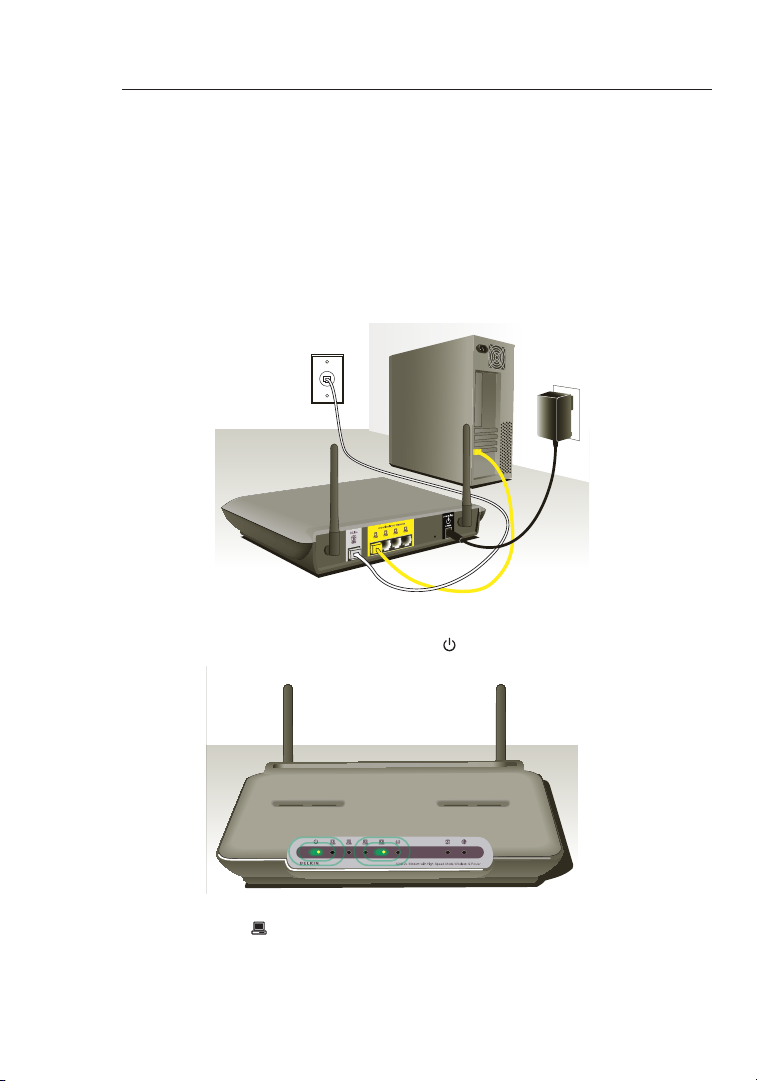
Powering Up your Router
1. Connect the suppli ed po we r a da pter to th e R ou ter p ower-input
plug labeled “Powe r” .
Note: For safety and perform an ce reas on s, on ly us e t he su pp lied
power adapter to prevent damage to the Router.
2. After connect in g t he po we r a da pter and t he po wer s ourc e i s
turn ed on , t he Ro ut er ’s power icon
be on. It mi ght t ake a fe w min ut es fo r t he Ro ut er to fu ll y s et up .
on the fron t pan el sh ou ld
3. Turn on your comp ut ers. After your computers boot up, the LAN
status LED o n the front of the Router will be on f or ea ch po rt
to which a w ired co mp ut er is co nn ected. These lights show
you the connection and activ it y s ta tus. Now y ou are ready to
configure the Router for ADSL connect io n.
Page 15
1312
Setting Up your Computers
In order for your computer to properly communicate with your Router, you
will need to change your computer’s “TCP/IP Ethernet” settings to “Obtain
an IP address automatically/Using DHCP”. This is normally the default
setting in most home computers.
You can set up the computer that is connected to the ADSL modem FIRST
using these steps. You can also use these steps to add computers to your
Router after the Router has been set up to connect to the Internet.
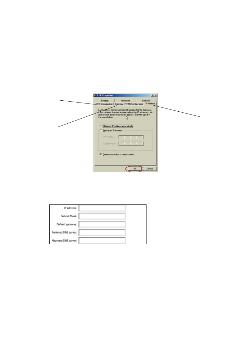
Manually Configuring Network Adapters in Windows XP, 2000, or NT
1.
Click “Start”, “Settings”, then “Control Panel”.
2. Double-click on the “Network and dial-up connections” icon
(Windows 2000) or the “Network” icon (Windows XP).
3. Right-click on the “Local Area Connection” associated with your
network adapter and select “Properties” from the drop-down menu.
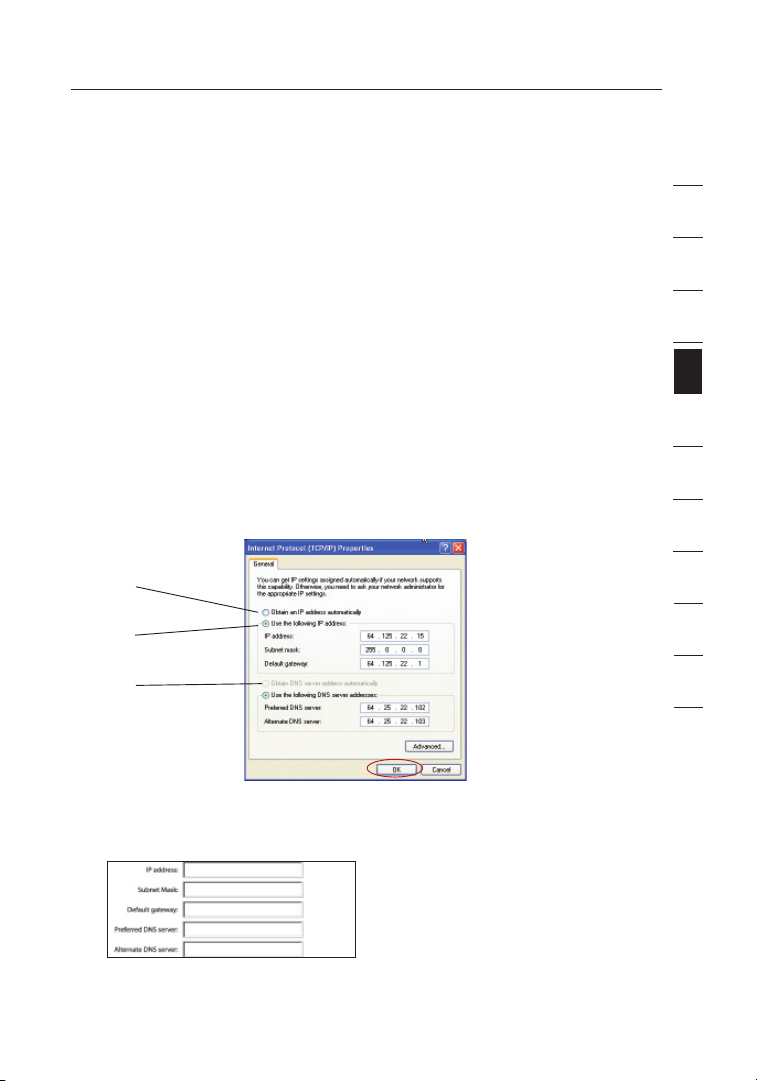
4. In the “Local Area Connection Properties” window, click “Internet
Protocol (TCP/IP)” and click the “Properties” button. The following
screen will appear:
(1)
(2)
(3)
1
2
3
4
sec t ion
5
6
7
8
9
10
11
12
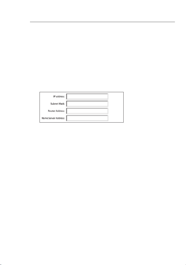
5. If “Use the following IP address” (2) is selected, your Router will need to
be set up for a static IP connection type. Write the address information
the table below. You will need to enter this information into the Router.
6. If not already selected, select “Obtain an IP address automatically”
(1) and “Obtain DNS server address automatically” (3). Click “OK”.
Your network adapter(s) are now configured for use with the Router.
13
Page 16
Setting Up your Computers
15
Manually Configuring Network Adapters in Windows 98SE or Me
1.
Right-clic k on “My Networ k Nei gh bo rhood” and select
“Properties” from the drop -d own m enu.
2. Sel ec t “ TC P/IP -> se ttings” for your install ed ne tw ork a dapter.
You wi ll se e the foll ow ing w indow.
(1)
(3)
(2)
3. If “ Sp ec ify a n I P a dd ress ” is selec te d, yo ur Ro uter will need
to be s et up fo r a static IP connec ti on ty pe. Wri te th e add ress
informat io n i n the tabl e bel ow. You will need to enter this
informat io n i nt o t he Ro ut er.
4. Write the IP address and subnet mask from th e “ IP Ad dres s”
tab (3).
5. Cli ck th e “ Ga te way” tab (2). Wri te th e g at eway addres s d ow n i n
the chart.
6. Cli ck th e “ DN S C on figuratio n” ta b (1). Write the DNS address(es)
in the chart.
7. If not already selecte d, se le ct “O btain an I P a dd re ss
automati ca lly” on th e I P add ress tab. Clic k “OK ”.
Restart the comput er. W he n t he co mp uter re st arts, your network
adapter( s) are now configured for use with the Router.
Page 17
1514
Setting Up your Computers
Set up the c omputer that is connected to the cable or DSL modem
by FIRST using these steps. You c an al so us e t he se st eps t o a dd
computer s to your Route r aft er th e Rou te r h as be en se t up to connect
to the Inter ne t.
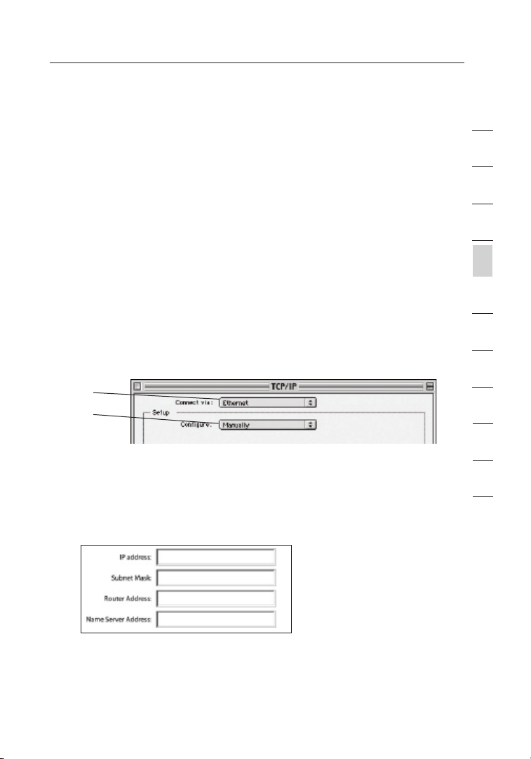
Manually Configuring Network Adapters in Mac OS
up to 9.x
In order for your computer to properly comm unicate with your Router,
you wil l need to chan ge y our Mac computer’s TCP/IP settings to DHCP.
1. Pul l d ow n t he Ap pl e m enu. Select “Control Panels” and
select “TCP/I P” .
2. You will see the TCP/IP control panel. Select “Ethe rnet Built-In”
or “Ether ne t” in th e “ Co nn ect v ia:” drop -down menu (1).
(1)
(2)
3. Nex t to “Co nf ig ure” (2), if “M an ually” is selected, your Router
will need to be s et up fo r a static IP connec ti on ty pe. Wri te th e
address informati on in the table belo w. You w ill n eed t o e nt er th is
informat io n i nt o t he Ro ut er.
1
2
3
4
sec t ion
5
6
7
8
9
10
11
12
15
Page 18
Setting Up your Computers
17
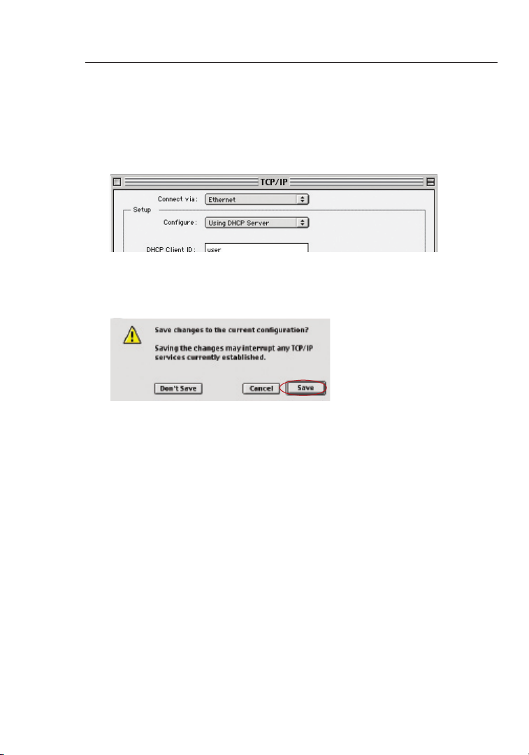
4. If not alre ad y s et , a t “ Co nf igure:”, choose “Using DHCP
Server”. This will tell the compu te r t o obt ai n a n IP address
fro m t he Ro ut er.
5. Clo se th e w in dow. I f y ou ma de an y cha ng es, t he fo llowing
window will appear. Cli ck “S av e”.
Restart the comput er. W he n t he co mp uter re st arts, your network
settings are now c onfigured for use w ith t he Ro uter.
Page 19
1716
Setting Up your Computers
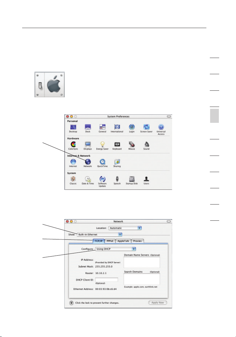
Manually Configuring Network Adapters in Mac OS X
1.
Click on the “System Pre fere nces” icon.
2. Sel ect “ Network” (1) from the “System Pre fere nces” menu.
(1)
3. Sel ect “ Built-in Ether net” (2) next to “Show” in the
Network menu.
(2)
(3)
1
2
3
4
sec t ion
5
6
7
8
9
10
11
12
(4)
17
Page 20
Setting Up your Computers
19
4. Sel ect the “TCP/IP” tab (3). Next to “Configure” (4), you should
see “Manually ” or “Usin g DHC P” . I f you do not, check the
PPPoE tab (5) to make sure th at “C on nect using PPPoE” is NOT
selected . If it is, you will need to configure y our R outer for a
PPPoE connect io n t yp e u si ng yo ur us er na me an d p as sword.
5. If “ Ma nually” is selected, your Route r wil l nee d to be set up
for a s tatic IP c onnection type. Write the address i nformation
in the table below. You wil l nee d to enter this info rm ation into
the Router.
6. If not already selecte d, se le ct “U sing DHCP” next to “ Configure”
(4), then click “Appl y Now ”.
Your n et work adapter(s ) are now configured for u se wi th the R outer.
Page 21
1918
Setting Up your Computers
Recommended Web Browser Settings
In most cases, you will not need to m ake a ny ch anges to y our w eb
bro wser’s set ti ngs. If yo u a re having trouble accessi ng th e Int er net or
the advanced web-b as ed us er in terface, then change your browser’s
settings to the re commended sett in gs in th is se ct ion.
Internet Explorer 4.0 or Higher
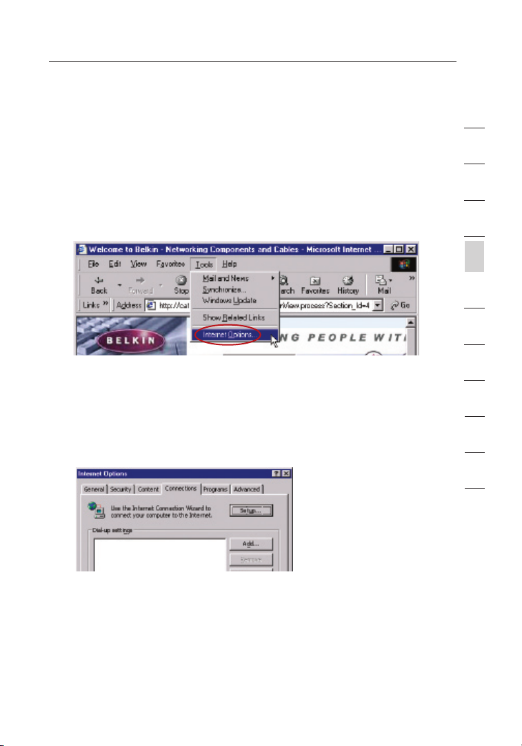
Start your web b ro ws er. S elect “Tool s” th en “I ntern et Op ti ons”.
1.
2. In the “Int er net Options” screen, there are th ree selecti on s:
“Never dial a connectio n” , “ Di al wh enever a n etwork connectio n
is not pres en t”, a nd “A lways dial my d efault connect io n”. I f y ou
can make a s election, select “Nev er di al a conne ct ion”. If y ou
cannot make a selection , go to the next step.
1
2
3
4
sec t ion
5
6
7
8
9
10
11
12
3. Und er th e “ In te rnet Optio ns ” s cree n, cl ic k o n “Co nn ections” and
select “LAN Settin gs …”.
19
Page 22
21
Setting Up your Computers
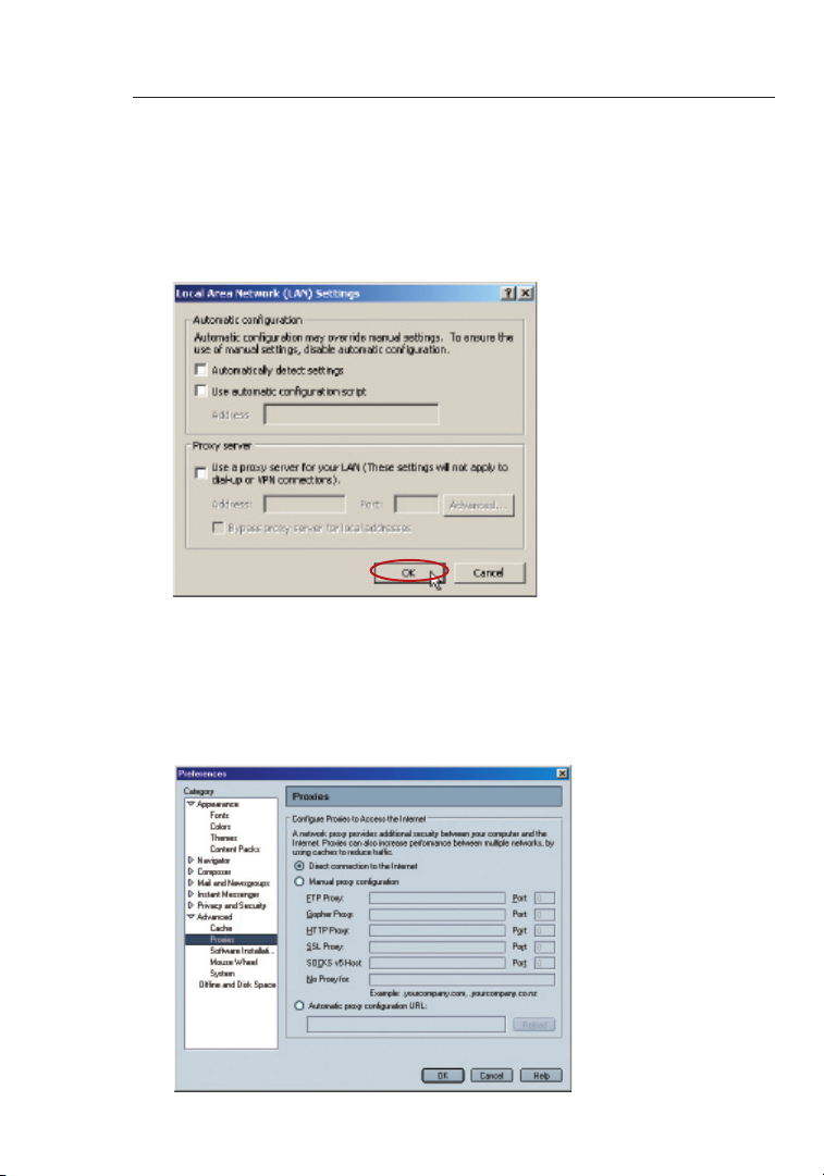
4. Mak e sure there a re no check marks next to any of the displayed
options: “Aut om atically detect setti ng s”, “ Use a utomatic
configur at ion s cript”, and “Use a p ro xy se rv er”. Click “OK”. Then
click “OK” again in the “Intern et Op tions” page.
Netscape Navigator 4.0 or Higher
1.
Start Netscape. Clic k on “Edit ” the n “Preferences” .
2. In the “Preferences” windo w, click on “Advan ce d” th en se lect
“Proxies”. In the “Pro xies” window, select “Direct connectio n to
the Inter ne t”.
Page 23

2120
Configuring your Router with the Setup Wizard
Running the Setup Wizard
1. You ca n acc es s t he we b- based manageme nt us er in te rface of t he
Router using the Internet brow ser o n a comp ut er co nnected to
the Router. Type “ 192.168.2 .1 ” ( do no t typ e in anyth in g e ls e s uc h
as “http://” or “www”) in your browser’s ad dres s bar. The n press
the “Enter” key.
Note: It is stro ng ly reco mm ended that you use a co mp uter
physical ly co nn ected to t he Ro uter with an RJ 45 ca ble f or in itial
setup. Using a wirelessly connec te d c om puter for initial setup is
not re co mmended.
2. The following screen will appear in your browser to prom pt yo u
to log in. T he de fault User Name is “ Admin” and the default
Password is “ Admin”. Enter both User Name and Passwo rd, then
click the “Submit” butt on to log in.
1
2
3
4
5
sec t ion
6
7
8
9
10
11
12
Note: It is stro ng ly reco mm ended that you change the password
to your own for i ncre as ed se curity. Pl ea se read the follo wi ng
section, enti tl ed “M anually Configur in g y ou r R ou ter”, for details
on how to ch ange your password an d t o reference other
security feat ures .
21
Page 24
Configuring your Router with the Setup Wizard
23
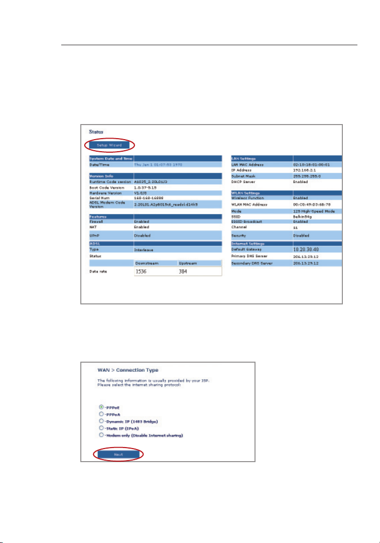
3. A Status page will follow showing deta il st at us of yo ur Ro ut er.
Next, click on the “Setup Wizard” button for express
configur at ion ( re co mmended).
4. Click on the “Setup Wizard” button to start the Router’s S et up
Wizard. The f irst step is to se le ct yo ur co nnection type (this
informat io n i s provide d by your ISP) and click “Next ”.
Page 25
2322
Configuring your Router with the Setup Wizard
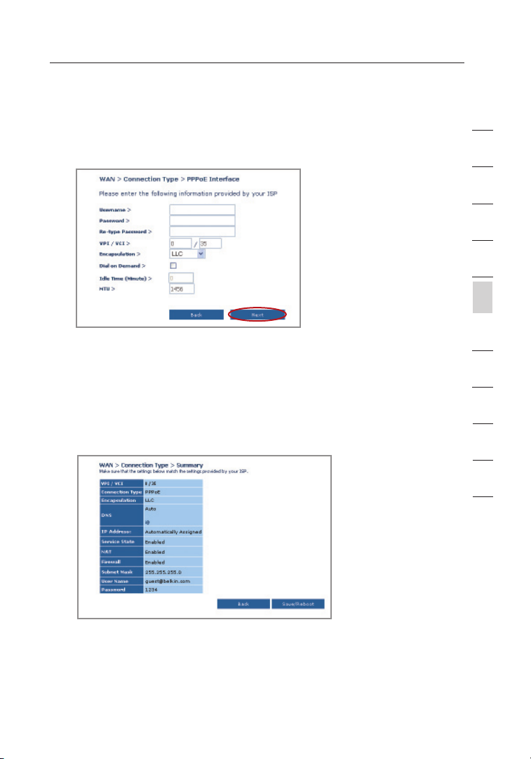
5. Now enter the re qu ired va lu es prov id ed by yo ur IS P. Fo r the
“PPPoE” or “PPPoA” page you will see the followi ng sc reen .
Enter the req uire d v al ues p ro vi de d b y y ou r I SP an d cli ck “N ex t”.
Note: For more detailed inst ru ction on o ther connection types ,
please refer to th e “ Ma nually Configu ri ng yo ur Ro uter” section of
this User Manual.
6. Double-c he ck th e s et tings shown on the f ollowing screen. You
can click “Back” to change the setting s or click “App ly ” t o
activate your sett in gs.
1
2
3
4
5
sec t ion
6
7
8
9
10
11
12
Note: You c an al wa ys rest ar t t he Se tu p W iz ard or use the
Navigati on Me nu on the left to change your setti ng .
23
Page 26

25
Configuring Your Router with the Setup Wizard
Connecting to the Wireless LAN
7.
Now you can connect to the Router via a wi re le ss -LAN-enab le d
computer with the follo wi ng de fault wireless LAN settings:
Wireless Channel = 11
SSID = belkin54g
Security = off
Note: Belkin strongly recommends that you enable wireless
security to WEP or WPA and chang e SSI D to somet hi ng of
your own. Please read t he Us er Ma nual for d etails on levels of
wireless security and how to change your securi ty se tt ings.
8. Congratu la tions! You h av e f in ished installing your new Belki n
Router. To te st yo ur In terne t con ne ction, open your browser and
visit any website, such as www.bel ki n. com/anz. For advanc ed
features and more de ta iled installatio n and secu ri ty se tup
informat io n, se e t he fo ll owing section, “Manua ll y C on figuring
your Router”.
Page 27
2524
Manually Configuring your Router
Understanding the Web-Based User Interface
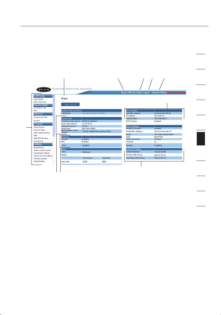
The home page shows you a q uick view of th e R ou ter’s stat us an d
settings . All adva nc ed se tup p ages can b e reach ed from this page.
(10)
(1)
(9)
(7)
1. Quick-Navigation Links
You ca n go directly to any of the Router’s U I pag es by clic ki ng
directly on t hese links. The links are d iv ided into logical
categori es an d grouped by tabs to make finding a particul ar
setting easie r to find. Clic ki ng on th e hea de r o f eac h tab will
show you a s hort description of the tab’s fu nction.
2. Home Button
The “Home” button is availab le in ever y pag e of the UI. Pressing
this button will take you back to the home page.
3. Help Button
The “Help” button gives you acces s to the Router ’s help pages.
Help is also available on many pages by clicking “more info” next
to certain section s of each page.
4. Login/Logout Button
This button enable s you to log in and out of th e R ou ter w ith t he
pre ss of on e but to n. Wh en yo u a re logged into the Route r, th is
button will change to read “ Logout”. Loggi ng in to th e Rou te r w il l
(2) (5)(4)(3)
(6)
(8)
1
2
3
4
5
6
sec t ion
7
8
9
10
11
12
25
Page 28

Manually Configuring your Router
27
take you to a s ep arate login page where y ou wi ll ne ed to en te r a
password. When you are lo gg ed in to th e R ou ter, you c an ma ke
changes to the settings . Whe n you are finished makin g cha ng es,
you can log out o f t he Ro ut er by cl ic king the “ Logout” button.
For more in fo rmation about loggi ng in to th e Rou te r, se e t he
section calle d “Lo gg ing i nto t he Ro uter”.
5. Internet Status Indicator
This indicato r is visib le in all pages of the Router, show in g
the connectio n sta tu s o f the Rout er. W he n t he in di cator says
“connect io n O K” in GREE N, th e Rou te r i s con ne cted to th e
Intern et. W hen t he Ro uter is no t c on nected to the Intern et , t he
indicato r wil l read “no connecti on ” i n RED . The indi ca tor i s
automati ca lly u pdated when you make changes to the settings of
the Router.
6. LAN Settings
Shows you the settings of the Local Area Ne twork (LAN) side of
the Router. Change s can be made to the settings by clickin g the
“LAN” “Quick Navig at ion” link on th e l ef t s id e o f the screen.
7. Features
Shows the status of the Router’s U PnP, NAT, and firewall
features. Changes can be made to the s ettings by clicking on any
one of the l inks or by cl ic king the “ Quick Navigation ” lin ks on the
left side of the scre en .
8. Internet Settings
Shows the settings of the Inter net/WA N s id e o f the Rout er th at
connects to the Inter net. Changes to any of these settings can be
made by clicking on the “Intern et/WAN ” “ Qu ick N avigation ” lin k
on the left side of th e s cree n.
9. Version Info
Shows the firmware version, boot -c ode v ersion, hardware
version, and seria l num be r o f the Rout er.
10. Page Name
The page you are on can be identif ie d b y thi s nam e. Th is ma nu al
will sometime s refer to pages by name. For instance, “LAN > LAN
Settings ” refers to the “LAN Settings ” pag e.
Page 29

2726
Manually Configuring your Router
Changing LAN Settings
All settings for the inter nal L AN se tup of t he Ro uter can b e v ie wed
and changed here.
Clicking on the header of the LAN tab (1) w ill t ake y ou to th e LAN
tab’s h ea der p age. A q ui ck de scription of the functions can be
found here. To view the settin gs or make chan ge s t o any of the LAN
settings , cli ck on “LAN Sett in gs” (2) or to view the list of connect ed
computer s, cl ic k o n “DH CP Cl ie nt Li st” (3).
(1)
(2)
(3)
1
2
3
4
5
6
sec t ion
7
8
9
10
11
12
27
Page 30

Manually Configuring your Router
29
LAN Settings
(1)
(2)
(3)
(4)
(5)
(6)
1. IP Address
The “IP addre ss” i s t he in te rnal IP address of t he Ro uter.
The default IP address is “1 92.168.2. 1” . To access the setup
interfac e, ty pe th is IP address into the address bar of y our
bro wser. This address can b e c ha nged if ne eded. To cha ng e
the IP addres s, ty pe in th e n ew IP address and click “Apply
Changes” . The IP address you choose should be a non-routable
IP. Example s of a non-routable IP are:
192.168. x. x ( wh ere x is anything betw ee n 0 and 255)
10.x.x.x (whe re x is an ything between 0 and 255)
2. Subnet Mask
There is no need to chan ge th e sub ne t m as k. Th is is a uniqu e,
advanced feat ure of your Belkin Route r.
3. DHCP Server
The DHCP server function makes setting up a network very easy
by assigning IP addresses to each computer on the network
automatically. The default setting is “On”. The DHCP server can
be turned OFF if necessary, however, in order to do so you must
manually set a static IP address for each computer on your network.
To turn off the DHCP server, select “Off” and click “Apply Changes”.
4. IP Pool
The IP Pool is th e r an ge of IP addresse s set asid e for dyna mi c
assignme nt to the compu te rs on yo ur ne tw ork. The d efault is
Page 31

2928
Manually Configuring your Router
2–100 (99 computer s) . I f you want to change this numb er, y ou
can do so by en te ring a n ew st ar ting and e nding IP a ddre ss an d
clicking on “Apply Chan ge s”. T he DH CP se rver can a ssign 100 IP
addresses automat ic ally. This means that you cannot spec if y a n
IP addre ss po ol la rger than 100 compu te rs. F or ex ample, starting
at 50 m eans you h ave t o e nd at 150 or lower so as not to ex ceed
the 100-clien t lim it . T he st ar ting IP ad dres s m us t b e low er in
number than the ending IP address.
5. Lease Time
Lease time is the length of time the DHCP server will re se rve
the IP addres s f or ea ch co mp uter. We recomm en d t ha t y ou
leave the lease time set to “Fore ver”. The default settin g is
“Forever”, meanin g tha t any time a compute r is assig ne d a n
IP addre ss by th e D HC P s er ve r, th e I P a dd ress will not chang e
for that particula r com pu ter. Setting lease times for short er
interval s, su ch as one day or one hour, frees IP ad dres se s a ft er
the specified peri od of time . Thi s als o mea ns th at a parti cu lar
computer ’s IP addres s m ay ch an ge ov er ti me. I f y ou ha ve se t any
of the other advanced features of the Router, such as DMZ or
client IP filters, thes e are dependen t on the IP address. For this
rea son, you w ill n ot wa nt th e I P a dd ress to change .
6. Local Domain Name
The default setting is “Belkin”. You can set a local domain name
(network name) for your network. There is no need to change this
setting unless you have a specific advanced need to do so. You can
name the network anything you want such as “MY NETWORK”.
1
2
3
4
5
6
sec t ion
7
8
9
10
11
12
29
Page 32

Manually Configuring your Router
31
DHCP Client List
You ca n vie w a list of the computers (k no wn as cl ie nt s), w hich are
connecte d to your netwo rk . You are ab le to vi ew th e IP address (1) of
the computer, the host name (2) (if the computer has been assigne d
one), and the MAC addre ss (3) of the comp ut er ’s Network Inte rf ace
Card ( NI C). P re ss ing t he “R efre sh ” (4) bu tt on wi ll up date the l ist. If
there ha ve be en an y c ha nges, the list will be up dated.
(1) (2) (3)
(4)
Internet WAN
The “Internet WAN” tab is where you will set up your Router to connect
to your Internet Service Provider. The Router is capable of connecting
to virtually any ADSL Service Provider’s system provided you have
correctly configured the Router’s settings for your ISP’s connection type.
Your connection settings are provided to you by your ISP. To configure
the Router with the settings that your ISP gave you, click “Connection
Type” (1) on the left side of the screen. Select the connection type you
use. If your ISP gave you DNS settings, clicking “DNS” (2) allows you to
enter DNS address entries for ISPs that require specific settings.
When you have finished making settings, the “Internet Status” indicator
will read “Connection OK” if your Router is set up properly.
(1)
(2)
Page 33

3130
Manually Configuring your Router
Connection Type
From the “Connection Type” page, you can select one of these five
connection types based on the instruction provided by your ISP:
• P PP oE
• P PP oA
• D yn amic IP (1 483 B ridged
• S ta tic I P ( IP OA)
• M od em On ly (D isable Inter ne t S ha ring)
Note: See Appendix C in this User Manual for some common DSL
Internet setting parameters. If you are not sure, please contact your ISP.
Select the type of connection you use by clicking the radio button
next to your connection type and then clicking “Next” (2).
(1)
)
(1)
1
2
3
4
5
6
sec t ion
7
8
9
10
11
12
(2)
31
Page 34

Manually Configuring your Router
33
Setting your ISP Connection Type to PPPoE or PPPoA
PPPoE (Point- to -Point Protocol over Ether ne t) is th e sta nd ard
method of connecti ng ne tw orked devices. It require s a user name and
password to a ccess the network of your ISP for c onnecting to the
Intern et. P PPoA (PPP over ATM) is similar to PPPoE, but is mostly
implemen te d i n the UK. Selec t PPP oE or PPPo A and clic k “Ne xt ”.
Then enter the informat io n p rovi de d b y you r ISP, a nd cl ic k “ Ap ply
Changes” to activa te yo ur se tt ings.
(1)
(2)
(3)
(4)
(5)
(6)
(7)
1. User Name - Enter the user name. (Assigned by your ISP).
2. Password - Enter your password. (Assigned by your ISP).
3. Retype Password - Confirm the password. (Assigned by your ISP).
4. VPI/VCI - Enter your Virtual Path Identifier (VPI) and Virtual Circuit
Identifier (VCI) parameter here. (Assigned by your ISP).
5. Encapsulation - Select your encapsulation type (supplied by your ISP)
to specify how to handle multiple protocols at the ATM transport layer.
VC-MUX: PPPoA Virtual Circuit Multiplexer (null encapsulation) allows
only one protocol running per virtual circuit with fewer overheads.
LLC: PPPoA Logical Link Control allows multiple protocols running over
one virtual circuit (more overhead).
6. Dial on Demand - By selecting “Dial on Demand” your Router will
automatically connect to the Internet when a user opens up a web browser.
7. Idle Time (Minutes) - Enter the maximum idle time for the Internet
connection. After this time has been exceeded, the connection will
be terminated.
Page 35

3332
Manually Configuring your Router
Setting your Connection Type to Dynamic IP (1483 Bridged)
This connecti on me th od br idges your network and ISP’s n et work
together. The Rout er wi ll ob ta in an IP address autom at ically from yo ur
ISP’s D HC P s er ver.
(1)
(2)
1. VPI/VCI - Enter your Virtual Path Identifier (VPI) and Virtual Circuit
Identifier (VCI) parameter here. These identifiers are assigned by your ISP.
2. Encapsulation - Se le ct LL C o r VC MUX your ISP uses.
1
2
3
4
5
6
sec t ion
7
8
9
10
11
12
33
Page 36

Manually Configuring your Router
35
Setting your ISP Connection to Static IP (IPoA)
This connecti on ty pe is also call ed “C la ssical IP over ATM” or “C LIP”,
which your ISP pro vides a fi xed I P f or yo ur Ro ut er to co nn ect t o
the Inter ne t.
(1)
(2)
(3)
(4)
(5)
1. WAN IP Address – Enter an IP address a ssigned by your ISP for
the Router WA N i nt erface.
2. WAN Subnet Mask - Enter a subnet mask assign ed by your ISP.
3. Default Route - Enter a default gateway IP address. If the Router
cannot find the destina ti on ad dres s w it hin i ts lo cal n etwork, it will
forward the p ackets to the d efault gateway assi gn ed by yo ur IS P.
4. VPI/VCI - E nt er yo ur Virtua l Pat h Ide nt ifier (VPI) and Vir tual Circ ui t
Identifi er (V CI ) p ar ameter here. T hese identifiers are assigned by
your ISP.
5. Encapsulation - Se le ct LL C o r VC MUX your ISP uses.
Page 37

3534
Manually Configuring your Router
Setting your Connection Type to Modem Only (Disable
Internet Sharing)
In this mode, the Router simply acts as a bridge passing packet s
across t he DS L p or t. It requires additi on al so ftware to be instal le d o n
your computer s in order to a ccess the Inter ne t.
(1)
1. VPI/VCI - Ente r you r Virtual Path Iden ti fier (VPI) and Virt ua l C ircu it
Identifi er (V CI ) p ar ameter here. ( Assigned by your ISP).
2. Encapsulation - Se le ct LL C o r VC MUX. (Assi gn ed by yo ur IS P) .
DNS (Domain Name Server) Settings
A “Domain Name Server” is a server located on the Internet that
translat es Un iv ersal Resource Links (URLs) like “www.belki n. com” to
IP addre sses. Many ISPs do n ot requ ire you to enter this informa ti on
into the Router. The “Automa ti c f rom ISP” box (1) should be checked
if your ISP did n ot gi ve yo u a spec if ic DN S a dd re ss . I f you are using
a static IP connection type, then you may need to enter a specific
DNS address a nd se condary DNS address for your connection to work
pro perly. If your conne ct ion t ype i s d yn amic or PP PoE, it is li ke ly th at
you do not h ave t o e nt er a DNS address. Leav e the “Aut om at ic from
ISP” box checked. To en ter t he DN S a dd re ss se tt ings, uncheck the
“Automat ic from ISP” box and enter your DNS entries in the spaces
pro vided. Click “Apply Chan ge s” (2) to save the settin gs .
1
2
3
4
5
6
sec t ion
7
8
9
10
11
12
(1)
35
(2)
Page 38

Manually Configuring your Router
37
Wireless
The “Wi reles s” t ab lets you ma ke c hanges to the wireless network
set tings. From t his tab, you c an m ake changes to the wireless networ k
nam e (S SID), operating c hannel, and encryption security setting s.
Channel and SSID
(1)
(2)
1. Changing the Wireless Channel
There are a nu mb er of o perating channel s you c an choose f rom.
In the United States, t he re are 11 channels. I n the U ni te d Kingdom
and most of Europe, there are 1 3 channels. In a small number of
other countries, t he re a re other channel require me nt s. Your Router
is configured to operate on the proper channels fo r the c ou ntry you
reside in. The default channel is 11 ( un le ss you are in a coun tr y that
does not allow channel 11 ). The ch an ne l can b e changed if needed. If
there are other wireless networks operat in g in yo ur are a, your n et wo rk
should be set to operat e on a channel t ha t is di ffere nt than t he other
wireless networ ks . For b est performa nc e, use a channel that is at l ea st
five channels aw ay from the oth er wirel es s networks. For instance, if
another network is operating on channel 11, then set your network to
channel 6 or below. To c ha ng e the c ha nnel, select the channe l from
the drop-down list. Clic k “Apply Ch an ges”. The change is immediate.
2. Changing the Wireless Network Name (SSID)
To ide nt ify y our w irel ess n etwork, a name called the SSID (Service
Set Identifie r) is used . The defa ul t S SI D o f the Rout er is “bel ki n54g”.
You ca n cha ng e t hi s t o any th ing y ou wa nt to or yo u can leav e it
unchange d. If there are o th er wi re le ss ne tworks operating in your
are a, yo u w il l w an t t o m ak e s ure that your SSID is unique (does not
match that of another wireless networ k in the area). To cha ng e t he
SSID, type in the SSID that you want to us e i n the SSID fiel d (1) and
click “Apply Chang es ” (2). The chan ge is imme di ate. If yo u m ak e
Page 39

3736
Manually Configuring your Router
a change to the S SID, your wire le ss-equipp ed co mp uters may also
need to be recon fi gure d t o con ne ct to yo ur ne w net wo rk na me. R efer
to the documentati on of your wireless netw or k a da pter for i nformation
on making this change.
3. Using the ESSID Broadcast Feature
For security purpo se s, yo u c an ch oo se no t t o broadca st yo ur
network’s SSID. Doing so will keep your network name hidden from
computer s tha t are scanning for the presence of wireless networks.
To tur n off the broadcast of the SSID, select “DIS AB LE” a nd th en
click “Apply Chang es ”. Th e c ha nge i s i mm ediate. Each computer
now needs to be s et to co nn ect t o y ou r s pe cific SSID; an SSID of
“ANY” will no longer be accepted. Refe r to the docume nt ation of y our
wireless network adapt er fo r inf or mation on making this change.
Note: This advanced feature should be employed by advanced users only.
4. Using the Wireless Mode Switch
Your R ou ter c an op erate in t hree di fferent wireless modes:
“802.11g -A uto”, “802.11g-O nl y”, a nd “8 02.11g-LR S” . T he di fferent
modes are e xp lained below.
• 802.11g-Aut o -
802.11b and 802.11 g wireles s cli en ts si multaneousl y. This is th e
factory defau lt mo de an d ens ures succ es sful operation with all
Wi-Fi-co mp atible devices. If you have a mix o f 8 02 .11b and
802.11g clien ts in your netw or k, we recomm en d s et ting the R outer
to 802.11g-Au to mo de . T hi s s et ting should only be changed if you
have a specific re ason to do so .
• 802.11g-Onl y Mod e -
clients only. This mode is recomm en ded o nly i f y ou wa nt to
pre vent 802.11b client s from accessing your netw or k. To switch
modes, select the desired mode from t he “W irel ess M ode”
dro p-down box. Then, click “Appl y Cha ng es”.
• 802.11g-LRS Mode - We recom me nd yo u D O N OT us e thi s
mode unless you have a very specific reason to d o s o. Th is mo de
exists only to solve unique problems that may occur with some
802.11b clien t ada pt ers a nd is NO T nec es sary for i nteroperability
of 802.11g and 802.11b stand ards .
When to Use 802.11g-LRS Mode -
clients may not be compatibl e wit h 802 .1 1g wi re le ss te chnology.
These adapter s ten d to be of inferior desig n and may use older
drivers or technol og y. 802.11g -L RS (L imited Rate Support) allow s
I n t hi s m od e, th e R ou ter i s c om patible with
8 02.11g-Only mode work s wit h 802 .1 1g
I n s om e c as es, o lder 802.11b
37
1
2
3
4
5
6
sec t ion
7
8
9
10
11
12
Page 40

Manually Configuring your Router
39
these clients to be compatib le wi th th e new er 80 2. 11g t echnology.
Switchin g to this mode can solve problems that somet im es oc cur
with these clients . If you suspec t tha t you are using a cl ient adapter
that falls into this categor y, first check with the adapter vendo r to
see if there is a driver upda te . I f the re is no d river update availabl e,
switchin g to 802.1 1g -LRS mode may f ix yo ur prob le m. Pl ea se no te
that switchin g to 802.1 1g -LRS mode may d ecre ase 8 02.11g
performa nc e s li ghtly.
5. Protected Mode Switch
As part of t he 80 2.11g specificat io n, Prot ec ted m ode e nsures proper
operatio n of 802.1 1g cl ie nts a nd ac cess points when there i s h ea vy
802.11b traffic in the operating envi ronmen t. Wh en Protec te d m od e
is ON, 802.11g scans for other wireless network traffic before it
transmit s dat a. Th eref ore, using this mode in environment s wit h
HEAVY 802.11 b tra ffic or interference achi ev es be st pe rformance
res ults. If y ou are in an environment with very little —o r n o— wire le ss
network traffic, your best perfo rm ance will be ac hieved with Prot ected
mode OFF.
6. Using Frame Bursting
The Router support s Fra me Bu rs ting.
Selectin g “Fr am e B ur sting Mode” will re sult in al l d ev ices capable of
Frame Burstin g to funct io n i n Fra me Bu rs ting mode, and all c lients
not capable, to operate in normal 802. 11 g m od es. F rame Bursting
mode supports both Fram e Bur st ing-enabled devi ce s a nd no n- Frame
Bursting -e nabled devices simult an eously. Fr am e B ur sting mode is
based on the unrel eased 802.11e speci fi cation.
Selectin g “Off” will disabl e Tur bo mo de .
Page 41

3938
Manually Configuring your Router
Encryption/Security
Securing your Wi-Fi Network
Here a re a few diffe re nt wa ys yo u can maxi mi ze th e s ec urity of y our
wireless network and protect your data from pr ying eyes and e ars.
This section is intende d for the home, home office, and small office
user. At the time of t his U ser M anual’s pu bl ication, there a re three
encrypti on me th ods a vailable.
Name 64-bit Wired
Acron ym 64-b it W EP 128 -b it W EP WPA-TK IP WPA- AE S
Secur it y Good Bette r Best Best
Featu re s Stat ic k ey s Static k ey s D yn amic k ey
Equivalent
Privacy
Encry pt io n
keys based
on R C4
algor it hm
(typi ca ll y
40-bi t keys)
128-bit Wired
Equivalent
Privacy
More secu re
than 64-bit
WEP using a
key length o f
104 bits p lu s
24 a dditional
bits of sy st em
gener at ed
data.
Wi-Fi Protected
Access-TKIP
encry pt io n
and mutual
authe nt ic at io n.
TKIP (temporal
key integrity
pro to co l)
added so
that keys are
rot at ed a nd
encry pt io n is
stren gt hened.
WEP (Wired Equivalent Privacy)
WEP is a c om mon p ro to co l t ha t a dd s s ec urity to a ll Wi -Fi-compl ia nt
wireless pro ducts. WEP was designed to give wireless networks the
equivale nt le ve l o f pri va cy prot ec tion as a com pa rable wired ne tw ork.
With Protected
Access
Dynam ic key
encry pt io n
and mutual
authe nt ic at io n.
AES (Adva nc ed
Encry pt io n
Stand ar d) d oe s
not cause an y
throu gh put
loss.
1
2
3
4
5
6
sec t ion
7
8
9
10
11
12
64-Bit WEP
64-bit WEP was f ir st in trod uc ed wi th 64 -b it en cr yption, which includes
a key l ength of 4 0 b it s p lu s 2 4 add it ional bits of s ystem-gener at ed
data (64 bits total). Some hardware m anufacturers re fer t o 6 4- bit
as 40-bit encrypti on . S ho rtly after the technology was introduced ,
res earc hers found that 64-bit encrypti on wa s too easy to decode .
39
Page 42

Manually Configuring your Router
41
128-Bit WEP
As a result of 64-b it WE P’s potential secur it y w ea knesses, a more
secure m ethod of 1 28-bit encrypt io n w as de ve loped. 128-bit
encrypti on in cl udes a k ey le ng th of 10 4 bit s plu s 24 addit io nal b its o f
system-g en erated data (128 bits total). Some hardware m anufacturers
ref er to 12 8- bit a s 1 04 -bit encryptio n.
Most of the new w irel es s e qu ipment in the m arket today support s
both 64-bit and 128-bit WEP encry pt ion, but y ou mi ght h ave o lder
equipmen t tha t onl y sup po rts 6 4-bit WEP. All Belkin wireless products
will support both 64-bi t and 128- bi t W EP.
Encryption Keys
After selecti ng ei th er th e “ 64 -bit” or “ 128-bit WEP” encrypti on mo de ,
it is c ritical that you generate an encrypt io n k ey. If the encryption key
is not consistent throughou t the enti re wireless network, your wireless
networki ng de vi ces w ill b e u na ble t o c om municate with one another
on your network and you will not be a ble t o s uc cessfully commun ic ate
within your networ k.
You ca n ent er yo ur ke y by typin g in the hex key manual ly, or y ou ca n
type in a pa ssphrase in the “Passphras e” fi el d a nd cl ic k “ Ge nerate”
to cre at e a key. A h ex (h ex adecimal) key is a m ixture of nu mb ers a nd
letters from A–F a nd 0– 9. Fo r 6 4- bit W EP, you need to en ter 1 0 h ex
keys. For 128-bit WEP, you need to enter 26 hex keys.
For instance:
AF 0F 4 B C 3 D4 = 64-bit WEP key
C3 03 0 F A F 0F 4B B2 C3 D4 4B C3 D4 E7 = 12 8-bit WEP key
The WEP passphrase is NOT the same as a WE P k ey. Your w irel es s
card u se s t hi s p as sphrase to generate your WEP keys, but different
hardware m an ufacturers might have differe nt me thods for generating
the keys. If you have equipment from m ultiple vendor s in your
network, you can use the hex WEP key from yo ur Ro ut er or ac ce ss
point and enter it manually into the hex WEP key table in your
wireless card’s config ur ation scree n.
Page 43

4140
Manually Configuring your Router
WPA (Wi-Fi Protected Access)
WPA (Wi -F i P rotect ed Ac ce ss) i s a new Wi-Fi stan da rd that was
designed to improve upon the security feat ures of WEP. To u se WPA
security, the drivers and software of yo ur wi re le ss eq uipment must
be upgraded to support WPA. T hese updates will be found on the
wireless vendors’ webs it es. T here are two types of WPA security :
WPA- PSK ( no se rver) and WPA (with radius serve r) .
WPA-PSK (no server)
This method uses what is known as a P re -S ha re d key as the Network
key. A Netwo rk ke y is basic al ly a pas sw ord that is between eigh t
and 63 characters long. It can be a c ombination of letters , num be rs,
or characters . Eac h cli en t u se s t he sa me Ne tw ork k ey to ac ce ss th e
network. Typicall y, this is th e m od e t ha t w il l b e use d in a
home environment.
WPA (with radius server)
With this system, a radius server dist ri butes the Network key to
the clients automa ti cally. Thi s is typic al ly fo und i n a busi ne ss
environment. For a list of B elkin wireless pro ducts that support WPA,
please visit our websit e at www.be lk in .com/netw or ki ng.
1
2
3
4
5
6
sec t ion
7
8
9
10
11
12
41
Page 44

Manually Configuring your Router
43
Wireless G Router
Wireless G Notebook
Network Car
d
Wireless G Desktop
Network Car
d
Wireless G Desktop
Network Car
d
Sharing the Same Network Keys
Most Wi-Fi products ship with securit y tur ned off . S o onc e you have
your network worki ng , y ou ne ed to acti va te WE P o r WPA and m ake
sure y ou r w irel es s n et working devices are sharing the same
Network key.
Network key=
MyPassword
Network key=
MyPassword
Network key=
MyPassword
Network key=
WRONG Password
The Wire less G D es ktop Network Card c annot access the network
because it is using a diff eren t Net wo rk ke y t ha n t he Ne tw ork k ey th at
is configured on t he Wi re le ss G Rou te r.
Page 45

4342
Manually Configuring your Router
Using a Hexadecimal Key
A hexadecimal key is a mixture of nu mb ers a nd le tters fro m A –F an d
0–9. 64-bit keys are fi ve tw o-digit number s. 12 8- bit k eys a re 13
two-digi t num be rs.
For instance:
AF 0F 4B C3 D4 = 64-bit key
C3 03 0F AF 0F 4B B2 C3 D4 4B C3 D4 E7 = 128- bi t k ey
In the boxes below, make up yo ur ke y b y wri ti ng in tw o cha ra cters
between A–F and 0–9 in each box. You wi ll us e thi s key to program
the encryptio n set ti ngs o n y ou r R ou ter a nd yo ur wi re le ss co mputers.
®
Note to Mac users: Original Apple AirP or t
64-bit encryp ti on on ly. Apple AirPo rt 2 products can suppor t 64- bi t o r
128-bit encry pt ion. Please check your product to see w hich version
you are usi ng . I f y ou ca nn ot co nf igure y ou r n et work with 128-bit
encrypti on , t ry 64 -b it en cryption.
p rodu ct s s up port
1
2
3
4
5
6
sec t ion
7
8
9
10
11
12
43
Page 46

Manually Configuring your Router
45
WEP Setup
64-Bit WEP Encryption
1.
Select “64-bi t WEP ” from the dro p-down menu.
2. After selectin g you r WEP encr yp tion mode, you can e nter your key
by typing in the hex k ey ma nually.
A hex ( hexadecimal ) key is a mixture o f n um bers and l etters from A– F
and 0–9. For 64-bit WEP, you need to enter 10 h ex ke ys.
For instance:
AF 0F 4B C3 D4 = 64-bit WEP key
3. Click “Apply Change s” to fini sh . E nc ryption in the Router is now
set. Each of your computers on your wireless network will now
need to be c onfigured w ith t he sa me se curity setting s.
WARNING:
fro m a comp ut er wi th a w ireles s cli en t, yo u w il l n ee d t o ens ure that
security is turn ed ON fo r t hi s w ireles s cli en t. If th is is not done, you
will lose your wireless connecti on .
If you are confi gu ring the W irel ess R outer or a ccess point
Page 47

4544
Manually Configuring your Router
128-Bit WEP Encryption
1.
Select “128-b it WE P” from the drop-down menu.
2. After selecti ng yo ur WE P enc ry ption mode, you can enter your
key manually by typing in the hex key manually.
A hex ( hexadecimal ) key is a mixture o f n um bers and l etters from
A–F and 0–9. For 128-bit WEP, you need to enter 26 h ex ke ys.
For instance:
C3 03 0F AF 0F 4B B2 C3 D4 4B C3 D4 E7 = 128-bit WEP key
3. Click “Apply Change s” to fini sh . E nc ryption in the Router is now
set. Each of your computers on your wireless network will now
need to be c onfigured w ith t he sa me se curity setting s.
WARNING:
fro m a comp ut er wi th a w ireles s cli en t, yo u w il l n ee d t o ens ure that
security is turn ed ON fo r t hi s w ireles s cli en t. If th is is not done, you
will lose your wireless connecti on .
If you are confi gu ring the W irel ess R outer or a ccess point
1
2
3
4
5
6
sec t ion
7
8
9
10
11
12
45
Page 48

Manually Configuring your Router
47
Changing the Wireless Security Settings
Your R ou ter i s e qu ipped with WPA (Wi-F i Protect ed Ac ce ss), the
latest wireless securi ty st an dard . It also suppo rt s t he le ga cy se curity
standard, WEP (Wired E quivalent Privac y) . B y def au lt, w irel ess
security is disabl ed . To enable secur it y, you must first determine
which standard you want to u se. To acces s the secu ri ty se ttings, click
“Securit y” on the Wireless tab.
WPA Setup
Note: To us e WPA security, al l y ou r c li ents must be up graded
to drivers and software that support it. At the time of th is Us er
Manual’s publication , a securi ty pa tc h d ow nload is a vailable free
fro m M ic ro so ft. T his p atch works only with the Windows XP operating
system. You a lso n eed t o d ow nload the latest driver for your Belkin
Wireless G De sktop or N otebook Networ k Card from th e B el kin
support site. Othe r ope ra ting systems are no t s up ported at this time.
Microsoft’s p at ch on ly su pports devices with WPA-enabled driver s
such as Belkin 802.11g products.
There are two types of WPA se cu ri ty: W PA-PS K (no serv er ) a nd WPA
(with radius serve r) . W PA-PSK (no server ) use s a so-cal le d
Pre -Shared k ey as th e sec ur ity k ey. A Pre- Shared ke y i s a passwo rd
that is between eight and 63 character s lon g. It can be a combinatio n
of letters, number s, an d oth er ch ar acters. Each client uses the same
key to access the network. Typically, th is mo de wi ll be us ed in a
home environment.
WPA (wi th ra di us se rver) i s a co nf ig uration wherein a r adius server
distribu te s t he ke ys to the clien ts au to matically. T his i s t yp ically used
in a bu siness environment.
Page 49

4746
Manually Configuring your Router
Setting WPA-PSK (no server)
Fro m t he “S ec urity Mode” drop-down menu, select “WPA-PSK
1.
(no server)”.
2. For Encryption Techniqu e, se le ct “T KIP” or “A ES”. This setting will
have to be i dentical on the clients that you set up.
3. Enter your Pre-Shared k ey. This can be from ei gh t t o 6 3 cha ra ct ers
and can be l etters, numbers, or symbol s. Th is sa me ke y mus t be
used on all of th e c li ents that you s et up . F or ex am ple, your PSK
might be something like : “Sm it h f am ily n etwork key”.
4. Click “Apply Change s” to fini sh . You must now set all clients to
match these settin gs .
1
2
3
4
5
6
sec t ion
7
8
9
10
11
12
47
Page 50

Manually Configuring your Router
49
Setting WPA (with radius server) Settings
If your network uses a radius server to distribu te ke ys to the clien ts ,
use this setting.
1. Fro m t he “S ec urity Mode” drop-down menu, select
“WPA—Radius server)” .
2. For Encryptio n Techniq ue , s el ect “ TKIP” or “ AES”. This setting
will have to be i dentical on the clients that you set up
3. Enter the IP addre ss of th e r ad iu s s er ver i nto t he “R adius
Server” field s.
4. Enter the radius key into the “Radius Key” field .
5. Enter the key interval. Key inter va l i s how ofte n the keys are
distribu te d ( in pa ck ets).
6. Click “Apply Chang es ” t o fin is h. You must now set all clients to
match these settin gs .
Configuring your Belkin Wireless G Network Cards to
Use Security
Please Note: This secti on provides informat io n o n how to config ure
your Belkin Wireless G Network Cards to us e s ec urity.
At this point, you should already have your Wireless Router or access
point set to use WPA or WEP. In ord er fo r y ou to gain a wireless
connecti on , y ou wi ll ne ed to set your wireless noteb oo k c ard and
wireless desktop card to us e t he sa me se cu rity settings.
Page 51

4948
Manually Configuring your Router
Connecting your Computer to a Wireless Network that Requires a
64-Bit or 128-Bit WEP Key
1.
Double-c li ck th e “ Si gnal Indicator” icon to bring up the “Wireless
Network” screen. The “Advan ce d” bu tton will allow you to vi ew
and configure more o pt ions of yo ur wi re le ss ca rd.
2. Under the “Wireless Network Properties ” tab , sel ec t a netw or k
name fro m t he “Avail ab le ne tworks” list and click “Configu re”.
3. Under “Data Encryp ti on” s elect “WEP”.
4. Ensure t he ch eck b ox “N etwork key is p ro vi ded f or me
automati ca lly” at th e b ot tom i s u nc hecked. If you are usi ng th is
computer to connec t to a corporat e net wo rk, p lease consult your
network admin is trator if this box n eeds to be ch ec ked.
5. Type y ou r W EP ke y in the “Netwo rk ke y” bo x.
1
2
3
4
5
6
sec t ion
7
8
9
10
11
12
Important: A WEP key is a m ixture of nu mb ers a nd le tters fro m A–F
and 0–9. For 128-bit WEP, you need to enter 26 keys. For 64-bit WEP,
you need to enter 10 k eys. This Network key needs to match the key
you assign to your Wire less Router or access point.
6. Click “OK” to save the settings.
49
Page 52

Manually Configuring your Router
51
Connecting your Computer to a Wireless Network that Requires
WPA-PSK (no server)
1.
Double-c li ck th e “ Si gnal Indicator” icon to bring up the “Wireless
Network” screen. The “Advan ce d” bu tton will allow you to vi ew
and configure more o pt ions of yo ur wi re le ss ca rd.
2. Under the “Wireless Network s” ta b, se le ct a net wo rk na me from
the “Ava ilable network s” li st an d cli ck “C on figure ”.
3. Under “Networ k Aut he ntication” selec t “WPA-PSK (No Server) ”.
4. Type y ou r W PA key in t he “N etwork key” box.
Important:
and 0–9. For WPA- PS K y ou ca n ent er ei gh t t o 63 keys. This Netw or k
key needs to match the key you a ssign to y our W irel es s R ou ter o r
access point.
WPA- PSK i s a mixt ure of numbers and letters from A–Z
5. Click “OK” to save the settings.
Page 53

5150
Manually Configuring your Router
Connecting your Computer to a Wireless Network that Requires
WPA (with radius server)
1.
Double-c li ck th e “ Si gnal Indicator” icon to bring up the “Wireless
Network” screen. The “Advan ce d” bu tton will allow you to vi ew
and configure more o pt ions of yo ur wi re le ss ca rd.
2. Under the “Wireless Network s” ta b, se le ct a net wo rk na me from
the “Ava ilable network s” li st an d cli ck “C on figure ”.
3. Under “Networ k Aut he ntication” selec t WPA.
4. Under the “Authent ic ation” tab, select the settings that are
indicate d by your netwo rk ad mi nistrator.
5. Cli ck “O K” to sa ve th e set ti ng s.
1
2
3
4
5
6
sec t ion
7
8
9
10
11
12
Setting Up WPA for a Non-Belkin Wireless Desktop and Wireless
Notebook Cards
For non-Belki n WPA Wire le ss De sktop and Wire less Notebook
Cards th at are not equipp ed wi th WPA-enabl ed so ft ware , a file from
Microsoft called “Wind ow s X P Sup po rt Pa tch f or Wi rele ss Protec te d
Access” is availab le as a free do wnload.
Please Note: The file that Microsoft has made availa bl e w or ks on ly
with Windows XP. Othe r ope ra ting systems are no t sup po rted at
this time.
51
Page 54

Manually Configuring your Router
53
Important: You also need to ensure th at th e w irel es s c ard
manufact urer supp or ts WPA and that you h ave d ownloaded and
installe d the late st dr iv er from thei r sup po rt si te.
Supported Operating Systems:
• Windows XP Professional
• Windows XP Home Edition
Setting Up Windows XP Wireless Network Utility to Use WPA-PSK
In ord er to use WPA-PSK, ensure y ou are using Wind ow s W irel es s
Network Utili ty by doin g the foll ow ing:
1. Under Windows XP, cli ck “S ta rt > Con trol Pane l >
Network Conne ct ions”.
2. Right-cl ic k o n “Wi rele ss Ne tw ork C onnection”, and
select “Propertie s” .
3. Clicking on the “Wireless Networ ks ” t ab wi ll di sp lay t he fo llowing
screen. Ensure th e “ Us e W in dows to co nfigure m y w ireles s
network setti ng s” ch eck b ox is ch ec ked.
Page 55

5352
Manually Configuring your Router
4. Und er th e “ Wire le ss Ne tworks” tab, click the “Configu re” butto n,
and you will see the f ollowing screen.
5. For a h ome o r s ma ll bu siness user, select “WPA-PSK” under
“Network Auth en tication”.
Note: Select “WPA” if yo u a re using this compute r to conne ct to a
corporat e net wo rk th at su pports an authenticat io n s er ver s uch a s a
radius server. Ple as e c on sult your network administ ra tor f or fu rther
informat io n.
6. Sel ec t “ TK IP” o r “ AE S” un der “ Data Encryptio n” . T hi s s et ting will
have to be i dentical to the Router that you set up.
7. Type in your encrypt io n k ey in the “Netw or k K ey ” b ox .
1
2
3
4
5
6
sec t ion
7
8
9
10
11
12
Importan t: En te r y ou r P re-S ha red key. T his c an be from eight to 63
characte rs an d can be letter s, nu mb ers, or sy mbols. This same key
must be used on a ll of th e cli en ts th at yo u s et up .
8. Click “OK” to apply settings .
53
Page 56

Manually Configuring your Router
55
Firewall
Your R ou ter i s e qu ipped with a fi re wa ll th at wi ll prot ec t y ou r n et work
fro m a wide arra y o f com mo n h ac ke r a tt acks including :
• IP Spoofing
• Land Attack
• Ping of Death (PoD)
• Denial of Service (DoS)
• IP with zero le ng th
• Smurf Attack
• TCP Null Scan
• SYN flood
• UDP flooding
• Tear Drop Attack
• ICMP defect
• RIP defect
• Fragment flood in g
The fire wall also masks common ports that are f re qu ently used to
attack networ ks . T he se po rts a ppear to b e “ St ealth”, meaning that
essentia ll y t he y d o not exis t to a would-be hack er. You can tur n the
firewall function off if ne eded; however, it is rec ommended that you
leave the firewall enabled. Disa bl ing t he fi rewa ll protec ti on wi ll no t
leave your network comp le tely vulnerable to hacker attac ks , b ut it is
rec ommended that you leave the firewall enabled.
Page 57

5554
Manually Configuring your Router
Virtual Servers
Virtual servers allow you to route external (Internet) calls for services such
as a web server (port 80), FTP server (Port 21), or other applications,
through your Router to your internal network. Since your internal
computers are protected by a firewall, machines from the Internet cannot
get to them because they cannot be “seen”. If you need to configure the
virtual server function for a specific application, you will need to contact
the application vendor to find out which port settings you need. You can
manually input this port information into the Router.
Choosing an Application
A list of po pular applicatio ns ha s bee n inc lu ded t o c ho ose f ro m. Cl ic k
on “Select a Service” then select your appl ic ation fro m t he drop-dow n
list. The settings will be transf er re d to the first row a vailable. Click
“Add” to save the setting for that applicat io n.
1
2
3
4
5
6
sec t ion
7
8
9
10
11
12
Manually Entering Settings into the Virtual Server
To man ua lly e nter settings, clic k on “Cust om Se rv er” a nd en ter a
name for the server. Enter the Server IP address in the space pro vi ded
for the intern al ma ch ine a nd th e p or t(s) re qu ired to pass . The n sel ec t
the prot ocol type (TCP or UD P), a nd th en cl ick “ Add”.
Opening ports in your firewall can pose a s ec urity risk. You c an enab le
and disable settin gs ve ry qu ic kly. It is re co mmended that you disable
the settings when you are no t u si ng a s pe ci fic a pplicatio n.
55
Page 58

Manually Configuring your Router
57
Client IP Filters
The Router can be configured to restrict access to the Internet, email, or
other network services at specific days and times. Restriction can be set
for a single computer, a range of computers, or multiple computers.
(1) (2) (3) (4)
To restric t Int er net access to a single compute r for exam pl e, en ter
a name of th e f il ter i n “ Fi lter Name” box
computer you wish to re strict access to in the I P f ie ld (2). N ext, enter
“80:80” in the Port field (3). Select protocol from th e “ Prot oc ol ”
dro p-down box (4). Click “Apply Chan ge s”. T he co mputer at the I P
address you s pecified will now be blocked from Inter ne t a cc ess.
(1) and I P a dd re ss of the
MAC Address Filtering
The MAC addre ss fi lter is a p ow er ful s ecurity feature that allows you
to specify which comput er s a re allowe d on the networ k. An y com pu ter
attempti ng to acce ss th e net wo rk th at is no t spe ci fied in th e f il ter l ist
will be denied access. When you enable this feat ure, you must enter a
name for the user and the M AC ad dres s o f eac h cli en t o n you r net wo rk
to allow network access . Nex t, cl ic k “ Ad d” to sa ve th e set ti ngs.
Page 59

5756
Manually Configuring your Router
DMZ (Demilitarized Zone)
If you have a c li ent P C t ha t c an not r un an In te rnet appli ca tion
pro perly fro m b eh ind t he fi re wa ll , y ou ca n o pe n t he cl ie nt up to
unrestricted two- wa y I nt ernet access . Thi s may be necess ar y i f the
NAT feature i s c au sing prob lems with an ap plication such as a game
or video conferencing appli ca tion. Use this feature o n a tempor ar y
basis. The compute r in the DMZ is not pro te cted from
hacker attack s.
To put a comp uter in the DM Z, e nter its LAN IP ad dress in the “Private
IP” fie ld and click “ Apply Chang es” for the ch ange to take effect.
Blocking an ICMP Ping
Computer hack er s u se wh at is know n as “ping in g” to fi nd po te ntial
victims on the Intern et. B y p in ging a s pecific IP addre ss an d
rec eiving a res po nse f ro m the IP address, a hacker can determine
that somethin g of interest might be there. The Router can be s et
up so i t w il l n ot respon d to an ICMP ping from th e o ut side. This
heighten s the leve l of secur it y o f you r Rou te r.
1
2
3
4
5
6
sec t ion
7
8
9
10
11
12
To tur n off the ping response, sele ct “B lo ck IC MP Pi ng” (1) an d cli ck
“Apply Change s” . T he Ro ut er wi ll no t respo ng to an ICMP Ping.
57
Page 60

Manually Configuring your Router
59
Utilities
The “Utilitie s” sc reen lets you manag e different paramete rs of the
Router and perform cert ai n a dm inistrative func ti ons.
Restart Router
Sometime s it may be necessar y to restart or reb oot t he Ro uter if it
begins workin g imp rope rl y. Restartin g or rebooting the Route r wil l
NOT delete any of your configurat io n s et tings.
Page 61

5958
Manually Configuring your Router
Restarting the Router to Restore Normal Operation
1.
Click the “Restart Rout er ” b ut ton.
2. The following message will appear. Click “OK” to restart your Router.
Restore Factory Defaults
Using this option will restore a ll of th e set ti ngs i n t he Ro ut er to th e
factory (defa ul t) se ttings. It is rec om mended that you back up y our
settings befo re you re store a ll of the defau lt s.
1. Click the “Restore Defaults ” but to n.
2. The following message will appear. Click “OK” to restore factory defaults.
1
2
3
4
5
6
sec t ion
7
8
9
10
11
12
59
Page 62

Manually Configuring your Router
61
Saving/Backup Current Settings
You ca n sav e you r cur rent conf ig uration by using this feature. Saving
your configur at ion w ill a llow you t o resto re it later if your settings are
lost or changed. It is rec om mended that you back up y our c urre nt
configur at ion b efore p er forming a firmware up date.
1. Click “Save”. A window called “File Download” will open. Click “Save”.
2. A window will open that allows you to select the location in
which to save the configurat io n f il e. Se lect a l oc ation. There a re
no res tr ictions on the file name, however, be sure t o n am e t he fi le
so you can l ocate it y ourself later. When you have selecte d the
location and entered the file name, click “Save ”.
Page 63

6160
Manually Configuring your Router
3. Whe n t he sa ve is co mp lete, you will see t he wi ndow below.
Click “Close” .
The configura ti on is no w sav ed .
Restore Previous Settings
This option will allow you to res tore a previousl y sav ed co nf iguration.
1. Click “Browse”. A window will open that allows you to select the
location of the configu ra tion file. All configurati on fi le s e nd wi th
a “.bin”. Locate the configu ra tion file you w ant t o resto re and
double-c li ck on it .
1
2
3
4
5
6
sec t ion
7
8
9
10
11
12
2. Then, click “Open” .
61
Page 64

Manually Configuring your Router
63
Firmware Update
Fro m t im e t o tim e, Be lk in ma y relea se ne w ver si ons o f t he Ro ut er’s
firmware. Firmware updates contain featu re improvements and fixes to
pro blems that may have existed. When Belki n releases new firmwa re,
you can download the firmware from th e B el kin u pdate website and
update your Router ’s firmware to th e l at est v ersion.
Updating the Router’s Firmware
1.
In the “Firmware Update” page, click “Browse”. A window will
ope n th at allows you to s elect the location of the firmware
upd ate file.
2. Bro wse t o t he fi rm ware fi le yo u dow nl oaded. Select the file by
double-c li cking on t he fi le na me.
3. Click “Update ” to upgra de to the lates t fir mw are ver si on.
Page 65

6362
Manually Configuring your Router
System Settings
The “System Settin gs ” p ag e i s whe re you can enter a n ew
administ ra tor p assword, set t he ti me zo ne, e nable rem ot e
manageme nt , a nd tu rn on an d o ff the UPnP functio n of the Router.
Setting or Changing the Administrator Password
The Router ships with NO password entered. If y ou wi sh to ad d a
password for grea ter s ecurity, y ou ca n set a password here. Write
down your password and keep it in a saf e pla ce , a s you will need it if
you need to log i nto t he Ro uter in th e f ut ure. It is also recommended
that you set a pa ssword if yo u pla n to use the re mote management
feature of yo ur Ro uter.
Changing the Login Time-Out Setting
The login time-out opti on al lo ws yo u t o set the perio d of time that
you can be l ogged into the Router’s a dv anced setup interface . The
timer starts when there has been no ac tivity. Fo r exa mp le, y ou ha ve
made some changes in the advanced setu p int er face, then left your
computer alon e wit ho ut cl icking “Logout”. Assu mi ng th e t im e-out is
set to 10 mi nutes, then 10 minutes after you leave, the login sessio n
will expire. You wil l hav e to log into the Router again to make any
more c ha nges. The login time-out opti on is for secur it y p ur poses and
the default is set to 10 mi nutes.
1
2
3
4
5
6
sec t ion
7
8
9
10
11
12
Note: Only one computer can be logged into the Router ’s advanced
setup interfa ce at one time.
63
Page 66

Manually Configuring your Router
65
Setting the Time and Time Zone
The Router keeps time by connecti ng to a Simple Netwo rk Ti me
Pro tocol (SNTP) server. Thi s all ow s t he Ro ut er to sy nc hron iz e t he
system clock to the global Internet. The synchronized clock in the
Router is used to rec ord the securi ty lo g and cont rol clien t fil te ring.
Select desired NTP time servers and the time zone that you res ide
in, then click “Apply Change s” . T he sy st em cl ock m ay no t u pd ate
immediat el y. Allow at least 15 minutes for the Router to contact the
time servers on the Intern et an d g et a response. You cannot set the
clock yoursel f.
Enabling Remote Management
Before y ou en able this advanced featu re of your Belkin Router, MAKE
SURE YOU HAVE SET THE A DMINISTRATOR PASS WO RD. R emote
manageme nt al lo ws yo u t o mak e cha ng es to yo ur Ro ut er’s setti ng s
fro m a ny where o n the Inte rnet.
Click on the “Change Setting s” bu tt on to br in g u p the “Rem ot e
Manageme nt ” p ag e.
There are two method s of remotely manag in g t he Ro ut er. T he fi rst
is to a llow access to the R outer fro m a ny wh ere on the Internet by
selectin g “An y IP address can re motely manage the Router”. By
typing in your WAN IP address from an y c omputer on the Interne t,
you will be pres en ted w ith a lo gi n s cree n whe re you need to type in
the password of yo ur Ro uter.
The second method is to allow a specific IP address o nly t o remot el y
manage the Router. This is more s ecure, bu t l es s c on venient. To us e
this method, enter the IP address you know you w ill b e a cc essing the
Router from i n t he sp ac e p rovi de d a nd se le ct “O nly t his I P a dd re ss
can re mo tely manage the Router”. Befo re you enable this functio n,
it is S TRONGLY R EC OMMENDED that you set your adminis tr ator
password. Leaving the passw ord empty will potent ia lly o pen y our
Router to intrusio n.
Page 67

6564
Manually Configuring your Router
Click on the “Apply Changes” butt on to save your sett in gs.
Enabling/Disabling UPnP
UPnP (Univers al Pl ug -and-Play) is yet another advan ce d f ea ture
off ered by your Belk in Ro ut er. I t i s a techno lo gy th at offe rs se am less
operatio n of voice mess ag ing, video messaging, game s, an d oth er
applicat io ns th at are UPnP- co mpliant. Some applica ti ons req ui re
the Router’s f irew al l t o be confi gu re d in a specific way to operate
pro perly. Thi s usu al ly requ ires openin g TCP and UDP ports, and in
some instance s, se tt ing t rigger ports. An applicati on th at is UPnP complian t has the abili ty to comm un icate with the Router, basica ll y
“telling ” the Rout er wh ic h w ay it need s the firewall conf ig ured . The
Router ships with the UPnP feature disable d. If you are u sing any
applicat io ns th at are UPnP- co mpliant, and wish to take advantage of
the UPnP features, you can e nable the UPnP feature.
Click on the “Change Setting ” but to n t o bri ng up the “UPnP Sett in g”
page. Then select “On” for “Enabl e UPn P” . C li ck on th e “Ap pl y
Changes” butt on to save your sett in gs.
1
2
3
4
5
6
sec t ion
7
8
9
10
11
12
65
Page 68

Troubleshooting
Problem:
T he AD SL LE D i s not on.
Solution:
Check the connecti on be tw een t he Ro uter and A DSL l ine. Make
1.
sure t he ca bl e f rom the ADSL line is connecte d to the port on
the Router labeled “DSL Line ”.
2. Make s ure the Rout er ha s pow er. T he Po we r L ED on the fro nt
panel should be illumin at ed.
Problem:
T he In terne t LED is not on.
Solution:
Make sure t he ca bl e f rom the ADSL line is connecte d to the port
1.
on the Router labeled “DSL Line” and the ADSL LED is on .
2. Make s ure you have the correct VPI/VCI, user name , and pass wo rd
fro m y ou r I SP provid er.
Problem:
My connection type is static IP address. I can’t c on nect to
the Inter ne t.
Solution:
Since your connect io n t yp e i s sta ti c I P add ress , you r ISP must assi gn
you the IP a ddre ss , s ub net m ask, and g ateway address. Instead of using
the Wizard, g o t o “ Co nn ection Type”, and t hen s elect your connection
type. Click “Next” , sel ec t “ St atic IP”, and e nter your IP ad dres s, su bnet
mask, and default gatew ay in fo rmation.
Problem:
I’ve forgo tten or lo st my pa ss word .
Solution:
Pre ss an d h ol d t he “R es et” b utton on t he rear pane l for at least six
seconds to re store t he fa ct ory d efaults.
Page 69

Problem:
My wirel ess P C c an not c onnect to the R outer.
Solution:
Make sure t he wi rele ss PC has the same SSID settin gs as the
1.
Router, and you have the same security sett in gs on th e cli en ts
such as WPA or WEP encrypti on .
2. Make sure t he di st ance between the Router and wireless PC are
not too far away.
1
2
3
4
5
Problem:
The wire less network is often interru pt ed.
Solution:
Mov e yo ur wirele ss PC closer t o th e Ro uter to find a bet ter signal.
1.
2. The re may also be interfe renc e, po ss ibly caused by a m ic rowa ve
oven or 2.4GHz cordless phones. Chang e the loca ti on of th e
Router or use a d iffe rent wireless chan ne l.
Problem:
I can’t con ne ct to th e I nt er net wirelessly.
Solution:
If you are un able to connect to the Internet from a wireless comp uter,
ple ase check the followi ng i tems:
1. Loo k at the lights on you r Router. If you a re using a Belkin Router,
the lig hts should be as f ollows:
• The “Po wer” light should be on.
• The “Co nnected” light sh ould be on, and not bl inking.
• The “WAN” light shou ld b e either on or bli nking.
2. Ope n y ou r w irel es s u ti lity software by cl icking on the i con i n
the system tray at the bottom right-ha nd co rner of the scree n.
If you’re u si ng a B el ki n W irel es s C ard, the tray icon shoul d loo k
like this. T he ic on ma y b e red or g re en .
3. The exa ct window that opens will vary depending on the model of
wireless card you have; however, any of the uti lities should hav e
a list of “Av ailable Networks”— those wireless net works it can
con nect to.
6766
67
6
7
sec t ion
8
9
10
11
12
Page 70

Troubleshooting
69
Does the name of your wire le ss ne twork appear in
the re su lts?
Yes, my network name is listed—go to the troubleshoo ti ng
solution titl ed “I can’t connect to the Inter net w irel essly, but my
network name is listed” .
No, my network name is not listed—go to the trou bleshooti ng
solution titl ed “I can’t connect to the Inter net w irel essly, and my
network name is not listed”.
Problem:
I can’t con ne ct to th e I nt er net wirelessly, b ut my ne tw ork n ame
is listed.
Solution:
If the name of yo ur ne twork is l isted in t he “Ava il ab le Ne tworks” list,
please follow the steps belo w to conne ct wi rele ss ly:
1. Click on th e c or re ct ne tw ork n ame i n t he “Availab le
Networks ” lis t.
2. If th e net wo rk ha s s ec urity (encryptio n) en ab led, you w ill n eed t o
enter the network key. F or mo re inform at ion reg arding secu ri ty,
see the page e ntitled: “Chan gi ng th e Wireles s Sec ur ity S ettings”.
3. Wi thin a f ew se co nds, the t ray i con i n t he lo we r l ef t-hand
corn er of yo ur sc reen should turn gree n, in di cation a s uccessful
connecti on to the netwo rk .
Problem:
I can’t con ne ct to th e I nt er net wirelessly, a nd my ne tw ork n ame i s
not listed.
Solution
If the correc t n et work name is no t l is ted u nder “Ava ilable
Networks ” in the wireless utilit y, please attempt the follo wi ng
tro ubleshoot in g s te ps:
1. Temporari ly mo ve co mp uter, if p ossible, five to 10 feet from
the Router. Close the wireless utilit y, and re- op en it . I f the
Page 71

6968
Troubleshooting
correct network name now appears unde r “Availabl e Net wo rks”,
you may have a ra nge o r i nt erfere nce p ro bl em. P lease see the
suggesti on s d is cussed in Appendix B entitled “Impor ta nt Fa ctors
for Placement and Setup ”.
2. Usi ng a compu te r t ha t i s con ne cted to th e R ou ter v ia a net wo rk
cable (as opposed to wire lessly), ensure that “B ro ad cast SS ID” i s
enabled. This sett in g i s fou nd on the Route r’s wireless “Channel
and SSID” configur at ion p age.
If you are still un ab le to ac ce ss th e I nt er net after compl et ing
these steps, pleas e con ta ct Be lkin Tech nical Support.
Problem:
My wirel ess n etwork perform an ce is in co nsistent.
Data transfer is someti me s s lo w.
Signal strength is poor.
Difficulty establ is hing and/or maintaini ng a Virtual Privat e Net wo rk
(VPN) connect io n.
Solution:
Wireless technolo gy is radi o- based, which means connect iv ity a nd
the thro ughput perform an ce be tween devices decreases when
the distance betwe en de vi ces i ncre ases. Other factors that will
cause signal degra da tion (metal is generally the worst culpri t) are
obstruct io ns su ch as wa ll s a nd me ta l a pp liances. As a res ul t, th e
typical indoo r ran ge of your wireless devi ce s w il l b e bet we en 10 0
to 200 feet. Note also that connection spee d may decrease as you
move further from the R outer or a ccess point.
In ord er to dete rm ine i f w irel es s i ss ues a re related to range, we
suggest tempo ra rily moving the computer, if possibl e, fi ve to 10 feet
fro m t he Ro ut er.
Changing the wireless channel - Depen di ng on lo ca l w ireles s
traffic and i nterference, switchi ng th e wireles s cha nn el of yo ur
network can improve perform an ce an d reliabi li ty. The default
channel the Router is shippe d wit h is chann el 11 , you may choos e
fro m s ev eral other channels depe nd ing o n y ou r region; see the
section entit le d “ Ch anging the Wireless Channel” on page 37 for
instruct io ns on ho w to choos e oth er ch an nels.
1
2
3
4
5
6
7
sec t ion
8
9
10
11
12
69
Page 72

Troubleshooting
71
Limiting the wireless transmit rate - Limiti ng t he wirele ss t ransmit
rat e ca n help improve the maxi mum wireless range, and connection
sta bility. Most wireless cards ha ve t he a bility to limit the transmission
rat e. To change this property, go to the Windows Control Panel,
ope n “N etwork Connections” and doub le-click on your wireless
card’s connection. In th e “P roper ties” dialo g, select the “Config ure”
but ton on the “General” tab (Win dows 98 users will have to select the
wireless card in t he l ist box and th en c lick “Pro perties ”), then choose
the “Ad vanced” tab and selec t th e rate property. Wireless clie nt cards
are usually set to automatically adju st t he wirele ss transmit rate for
you , bu t doing so can cau se periodic disconnects when the wireless
sig nal is too weak; a s a rule, slower transmis sion rates are more
sta ble. Experiment with different connection rate s un til you find the
bes t on e for your env ironment; note that all available transmi ssion
rat es s hould be acceptab le f or b rowsi ng t he Inter net. For more
ass istance , see your wireless card’s user manual.
Problem:
I am ha ving diff ic ulty setting up Wired Eq uivalent Privacy (WEP )
security on a Belkin Router or Belkin Acces s Poi nt .
Solution
Log into your Wireless Router or access point.
1.
2. Op en yo ur we b b rows er an d typ e in IP address of t he Wi re le ss
Router or access point. (The Rout er de fa ult i s 1 92 .168.2.1, the
802.11g acces s poi nt is 192. 16 8.2.254 ). Log into your Router by
clicking on the “Login” butt on in the top right- ha nd co rner of the
screen. You wil l be asked to enter your passw ord. If you never
set a p assword, le ave t he pa ssword fi eld b lank and
click “Submit ”.
3. Cl ick t he “W irel es s” ta b o n t he le ft of your screen. Select
the “Encrypti on ” o r “Se cu rity” tab to ge t t o the secu ri ty
settings page .
4. Se lect “128-bit WEP” from th e d rop- do wn me nu.
5. Af ter s electing your WEP encrypti on mo de , y ou ca n typ e in
your hex WEP key manually, or yo u can type in a passphras e
in the “Passphrase ” fie ld an d cli ck “G en erate” to crea te a WEP
key from th e pas sp hrase. Click “Apply Chan ge s” to fi ni sh. You
must now set all of yo ur cl ients to m atch these settings. A hex
(hexadec im al) k ey is a mixtu re of numbers and letter s from A-F
Page 73

7170
Troubleshooting
and 0-9. For 128-bit WEP, you need to enter 26 hex keys.
F or ex ample:
C 3 0 3 0F AF 4B B2 C3 D4 4B C3 D4 E7 E 4 = 128- bi t k ey
6. Click “Apply Change s” to fini sh . E nc ryption in the Wire less
Router is now set. Each of your computers on your wireless
network will now need to be configured with the same
security sett in gs.
WARNING: I f you are configuri ng th e Wireles s Rou te r o r Acc es s
Point from a com pu ter w ith a wi rele ss cl ie nt, y ou wi ll ne ed to en su re
that security is turn ed on fo r t hi s w ireles s cli en t. If th is is not done,
you will lose your wire less connectio n.
Note to Mac users: Origi na l A pp le Ai rPort
64-bit encryp ti on on ly. Apple AirPo rt 2 products can suppor t
64-bit or 128-bit encry pt ion. Please check your Apple AirPort
pro duct to se e w hi ch ve rsion you are usi ng . I f you cann ot co nf igure
your network with 128-b it en cr yption, try 64-bit encrypt io n.
Problem:
I am ha ving diff ic ulty setting up Wired Eq uivalent Privacy (WEP )
security on a Belkin Wireless Card.
Solution:
The Wire less Card mu st us e the same key as the Wireless Router or
access point. For insta nc e, if yo ur Wi rele ss Ro ut er or ac ce ss po int
uses the key 0011223344 55 66778899AAB BC C, th en th e W irel es s
Card m us t b e set to the exact same key.
®
p rodu ct s s up port
1
2
3
4
5
6
7
sec t ion
8
9
10
11
12
1. Double-cl ic k t he “S ig nal I ndicator” icon to bring up the Wireless
“Network ” screen. The “Adva nc ed” b utton will allow you to v iew
and configure more o pt ions of yo ur Ca rd .
2. The “Adv an ced” button will allow you to view and c onfigure
more o pt ions of th e C ard.
3. On ce th e “ Ad vanced” button is clicked, the Belki n Wireles s LAN
Utility will appea r. Th is Ut il ity w ill a llow you t o m an age a ll th e
advanced feat ures of the Belkin Wireless Card.
4. Under the “Wireless Network Propertie s” ta b, se le ct a
network name from the “ Av ai lable networks” list and click the
“Properties” butt on .
71
Page 74

Troubleshooting
73
5. Under “Data Encrypt io n” se lect “WEP”.
6. En sure th e che ck bo x “Th e key is provided for me automatical ly ”
at the bottom is unchecked. If you are us in g t hi s c om puter to
connect to a corporate netwo rk , p le ase c onsult your network
administ ra tor i f t hi s b ox ne ed s t o be check ed .
7. Type your WEP key in th e “ Ne twork key” box.
Important: A WEP key is a mi xture o f num be rs an d l et ters from
A–F and 0–9. For 128-bit WEP, you need to enter 26 k eys. This
Network key needs to match the key you assign to your Wire less
Router or access point.
For example:
C3 03 0 F A F 4B B2 C3 D4 4B C3 D4 E7 E4 = 12 8-bit key
8. Cl ick “ OK”, and t hen “ Apply” to save the s ettings.
If you are NOT using a Belkin Wireless Card, please consult the
manufact urer for that wireless client card’s use r man ua l.
Problem:
Do Belkin pro ducts support WPA?
Solution
Note:
To use WPA sec ur ity, all your client s mus t be upgra de d
to drivers and software that support it. At the time of th is FAQ
publicat io n, a sec ur ity p atch download is available , for free,
fro m M ic ro so ft. T his p atch works only with the Windows XP
operatin g sys te m.
Download the patch here:
http://w ww. mi cros oft.com/dow nl oads/detail s.
aspx?Fam il yID=009d842 5- ce2b-47a4 -a be c-274845d c9 e91&display l
ang=en
You al so ne ed to down lo ad th e l at est d river for your Belkin Wireless
802.11g Deskt op or Note bo ok Ne twork Card f rom the Belkin
support site. Othe r ope ra ting systems are no t s up ported at this
time. Microsoft’s pa tch o nly s upports devices with WPA-enabled
drivers such as Belkin 802.1 1g produc ts .
Download the latest driver at:
http://web.belkin.com/support/networkingsupport.asp.
Page 75

7372
Troubleshooting
Problem:
I am ha ving diff ic ulty setting up Wi-Fi Protected Access (WPA)
security on a Belkin Wireless Router or Belkin Acces s Poi nt fo r a
home network.
Solution:
From th e “ Se curity Mode” drop-down menu, select “WPA-PSK
1.
(no server)”.
2. Fo r “ En cryption Technique”, sele ct “T KI P” or “A ES ”. Th is se tting
will have to be i dentical on the clients that you set up.
3. En ter y our p re -s ha re d key. This can be from eight to 63
characte rs an d can be letter s, nu mb ers, or sy mbols or s paces.
This same key must be used on al l o f the clie nt s t ha t y ou se t up.
For example, your PSK might be somethi ng li ke : “ Sm ith f amily
network key”.
4. Cl ick “ Apply Changes” to finish. You m ust n ow se t a ll cl ie nts t o
match these settin gs .
Problem:
I am ha ving diff ic ulty setting up Wi-Fi Protected Access (WPA)
security on a Belkin Wireless Router or Belkin Acces s Poi nt fo r
a business.
Solution:
If your network uses a radius server to distribu te ke ys to the clien ts ,
use this setting. This is typical ly us ed in a busines s env iron me nt.
1. From the “Security Mode” drop-dow n men u, se le ct “W PA
(with server) ”.
2. Fo r “ En cryption Technique”, sele ct “T KI P” or “A ES ”. Th is se tting
will have to be i dentical on the clients that you set up.
3. En ter t he IP ad dres s of the radius serv er in to th e “Ra di us
Server” field s.
4. En ter t he ra dius key i nto t he “R adius Key” field.
5. En ter t he ke y i nt erval. Key interval is how often the keys are
distribu te d ( in pa ck ets).
6. Cl ick “ Apply Changes” to finish. You m ust n ow se t a ll cl ie nts t o
match these settin gs .
1
2
3
4
5
6
7
sec t ion
8
9
10
11
12
73
Page 76

Troubleshooting
75
Problem:
I am ha ving diff ic ulty setting up Wi-Fi Protected Access (WPA)
security on a Belkin Wireless Card fo r a home netw or k.
Solution:
Clients must use the same key that the wireless router or access point
uses. For instance if the key is “Smith Family Network Key” in the wireless
router or access point, the clients must also use that same key.
1. Dou ble-click the “Sign al In di cator” icon to bring up t he “W irel es s
Network” screen. The “Advan ce d” bu tton will allow you to vi ew
and configure more o pt ions of yo ur Ca rd .
2. The “A dv anced” button will allow you to view and configure more
options of the Card.
3. Onc e the “A dv an ced” button is clicked, the Belkin Wireless LAN
Utility will appea r. Th is Ut il ity w ill a llow you t o m an age a ll th e
advanced feat ures of the Belkin Wireless Card.
4. Under the “Wireless Network Properties” tab, select a network name
from the “Available networks” list and click the “Properties” button.
5. Und er “N et work Authentic at ion” select “WPA- PS K ( no se rv er)”.
6. Type your WPA ke y in the “Netwo rk ke y” bo x.
Important: WPA-P SK is a mixture of n umbers and letters from
A–Z and 0–9. For WPA-P SK yo u can ente r eig ht to 63 charac te rs.
This network key needs to match the key you assign to your
Wireless Router or access point.
7. Cli ck “O K, th en “A pp ly” t o s av e t he se tt ings.
Problem:
I am ha ving diff ic ulty setting up Wi-Fi Protected Access (WPA)
security on a Belkin Wireless Card fo r a busi ne ss.
Solution:
Double -c lick the “ Signal Indicator ” ico n to bring up the “Wireless
1.
Network” screen. The “Advan ce d” bu tton will allow you to vi ew
and configure more o pt ions of yo ur Ca rd .
2. The “A dv anced” button will allow you to view and configure more
options of the Card.
3. Onc e t he “A dv anced” button is clicked , the Belk in Wi reless LAN
Page 77

7574
Troubleshooting
Utility will appea r. Th is Ut il ity w ill a llow you t o m an age a ll th e
advanced feat ures of the Belkin Wireless Card.
4. Und er th e “ Wi re le ss Ne twork Pro perties” tab, select a network
name fro m t he “Avail ab le ne tworks” list and click the
“Properties” butt on .
5. Und er “N etwork Authent ic ation” select “WPA” .
6. In t he “A ut he ntication ” tab , sel ec t t he se tt ings that are indic at ed
by your network adminis tr ator.
7. Cli ck “O K, th en “A pply” to save the settings.
Problem:
I am having difficulty setting up Wi-Fi Protected Access (WPA) security
and I am NOT using a Belkin Wireless Card for a home network.
Solution:
If you are NOT using a Belkin Wireless Deskto p or Wireless
Notebook Netw or k C ard and it is n ot eq uipped with WPA-e nabled
software, a f ile f ro m Mic roso ft ca ll ed “W indows XP Support Patch
for Wire less Prot ected Access” is available for free download.
Download the patch from Microsoft by searching the knowledge
base for Windows XP WPA.
Note: The file that Microsoft has made available works only with
Windows XP. Othe r ope ra ting systems are no t sup po rted at th is
time. You a ls o n ee d t o ens ure that the wireless card m anufacturer
supports WPA a nd th at yo u h av e d ow nloaded and installed the
latest driver from their support site .
Supported Operating Systems:
• Windows XP Pro fe ssional
• Windows XP Home Edition
1
2
3
4
5
6
7
sec t ion
8
9
10
11
12
Enabling WPA-PSK (no server)
Under Window s XP, cl ic k “ St art > Co nt rol Panel > Network
1.
Connecti on s”.
2. Ri ght-clickin g on the “Wireless Netwo rk s” ta b w il l d is play the
followin g screen. Ensu re the “Use Windows to configure my
wireless network setti ng s” ch eck b ox is ch ec ked.
75
Page 78

Troubleshooting
77
3. Un der t he “W irel es s N et works” tab, click the “Config ure” button ,
and you will see the f ollowing screen.
4. Fo r a home or small busin es s u se r, se lect “WPA- PS K” un der
“Network Admi ni stration”.
Note: Sel ec t W PA (with radius server ) if you are us ing t his
computer to connec t to a corporat e net wo rk th at su pports an
authenti ca tion server such as a r ad ius s erver. Please consu lt
your network admin is trator for further informa ti on.
5. Se lect “TKIP” or “AES” under “Date Encrypti on ”. Th is se tting will
have to be i dentical to the wirel ess rou te r o r acc es s p oi nt th at
you set up.
6. Type in your encrypti on ke y i n the “Net wo rk Ke y” bo x.
Important: Enter your pre- shared ke y. This can be f ro m eig ht
to 63 c haracters and can be letters, number s, or symb ol s. Th is
same key must be used on al l o f the clie nt s t ha t y ou se t up.
7. Cli ck “O K” to appl y set ti ngs.
What’s the difference between 802.11b, 802.11g,
802.11a, and Pre-N?
Currently there are four levels of wireless networking standards, which
transmit data at very different maximum speeds. Each is based on
the designation 802.11(x), so named by the IEEE, the board that is
responsible for certifying networking standards. The most common
wireless networking standard, 802.11b, transmits information at 11Mbps;
802.11a and 802.11g work at 54Mbps; and Pre-N works at 108Mbps.
Pre-N, the precursor to the upcoming 802.11n release, promises speeds
that exceed 802.11g, and up to twice the wireless coverage area. See
the following chart for more detailed information.
Page 79

7776
Troubleshooting
Wireless Comparison Chart
Wireless
Technology
Speed
Frequency
Compatibility
Coverage
Adoption
11Mbps 54Mbps 54Mbps 108Mbps
Common
household
devices such as
cordless phones
and microwave
ovens may
interfere with the
unlicensed band
2.4GHz
Compatible
with 802.11g
Depends on
interference
- typically
100–200 ft.
indoors
Mature –
widely adopted
802.11b
Common
household
devices such as
cordless phones
and microwave
ovens may
interfere with
the unlicensed
band 2.4GHz
Compatible
with 802.11b
Depends on
interference
- typically 100–
200 ft. indoors
Expected
to continue
to grow in
popularity
802.11g
802.11a
5GHz uncrowded
band
Incompatible
with 802.11b
or 802.11g
Less
interference
- range is
typically
50-100 ft.
Slow adoption
for consumers
-
more popular
in business
environments
Common
household
devices such as
cordless phones
and microwave
ovens may
interfere with the
unlicensed
band 2.4GHz
Compatible with
802.11g
or 802.11b
8x the
coverage of
standard 802.11g
Expected to
continue to grow
in popularity
1
2
3
Pre-N
Belkin
4
5
6
7
sec t ion
8
9
10
11
12
77
Page 80

Technical Support Information
79
Technical Support
For latest software updates or if you have any f urther questio ns
reg ardi ng in stallation of this product, please visit
www.belkin.com/networking
o r c on tact:
US: 877-736- 57 71 or
310-8 98 -1100 ext. 2263
Europe: 00 800 223 5 5 4 60
Australi a: 1800 235 546
New Zealand: 0800 235 546
Singapore: 800 616 1790
Page 81

7978
Appendixes
Appendix A: Glossary
IP Address
The “IP addre ss” i s t he in te rnal IP address of t he Ro uter. To acc es s
the advanced setup inte rf ace, type this IP ad dres s i nt o t he ad dress
bar of your brow se r. Th is ad dres s c an be chan ge d i f nee de d. To
change the IP address, type in th e n ew IP ad dress and click “Appl y
Changes” . The IP address you choose should be a non-routable IP.
Examples of a non-routable IP are:
192.168. x. x ( wh ere x is anything betw ee n 0 and 255)
10.x.x.x (whe re x is an ything between 0 and 255)
Subnet Mask
Som e ne tworks are far too large to allow all traffic to flood all its parts.
The se n etworks must be broken down into smaller, more manageable
sec tions, called subnets. The subne t mask is the netw ork addre ss p lus
the inf ormation reserved for identifying the “subnetwork”.
DNS
DNS is an ac rony m f or Do ma in Na me Se rv er. A Do main Name Server
is a se rver located on the Inter ne t t ha t t ra nslates URLs (Univers al
Resource Links) like www.belki n. com t o I P add ress es . M an y I SP s
do not requ ire you to enter this informa ti on in to th e R ou ter. If yo u
are us in g a stat ic IP co nn ec tion type, then you may n eed t o e nt er
a specific DNS address and s econdary DNS address for your
connecti on to work properly. I f y ou r c on nection type is Dynamic or
PPPoE, it is likely that you do not h ave t o e nt er a DNS address.
1
2
3
4
5
6
7
8
sec t ion
9
10
11
12
PPPoE
Most ADSL pro viders use PPPoE as the c onnection type . If you use
an ADSL modem to connect to the Inter ne t, yo ur IS P m ay us e PPP oE
to log you i nto t he se rvice.
Your c on nection type is PPPoE if:
1. Your I SP ga ve yo u a user name and passw ord which is req uire d
to connect to the Intern et .
2. Your I SP ga ve yo u sof tw are suc h as WinPo ET or Ente rnet300 that
you use to c onnect to the I ntern et .
79
Page 82

Appendixes
81
3. You have to double-c li ck on a deskt op ic on ot he r t ha n y ou r
bro wser to ge t o n t he In te rnet.
To set the Route r to use PPPoE, type in your user name and
password in t he sp aces prov ided. After you have typed in your
informat io n, cl ick “ Apply Changes”.
After you apply the changes, the “Inte rnet Status” indi ca tor w ill read
“connect io n O K” if your Rout er is set up properly.
PPPoA
Enter the PPPoA informa ti on in th e provide d spa ce s, an d c li ck “N ext”.
Click “Apply” to activa te yo ur se tt ings.
1. Use r n am e - En te r t he us er na me . ( As signed by your ISP).
2. Pas sword - Ente r you r pas sw ord. (A ss igned by y our I SP).
3. Retype Passw ord - Confirm the password. (Assigned by your ISP).
4. VPI /VCI - E nt er yo ur Virt ua l P at h I de ntifier (VPI) and Virtual Circ uit
Identifi er (V CI ) p ar ameter here. ( Assigned by your ISP).
Disconnect after X...
This feature is us ed to au to matically disc on nect the R outer fro m
your ISP when there i s n o act iv it y f or a spe ci fi ed pe riod of ti me. F or
instance , pla ci ng a che ck ma rk ne xt to this opti on an d ent er ing “ 5”
into the minute field will cause the Router to discon ne ct from the
Intern et af ter f ive m inutes of no In terne t act iv ity. This optio n sho ul d
be used if y ou pa y f or yo ur In te rnet servi ce by the minut e.
Channel and SSID
To cha ng e t he ch an nel o f o pe ration of the R outer, select the desired
channel from the d ro p- down menu and s elect your channel. Click
“Apply Change s” to save the setti ng . You can also change the SSID.
The SSID is the e quivalent to the wire less network’s na me. You can
make the SSID anything you want to. If there a re other wireless
networks in your area, you s hould give your wireless network a unique
name. Click inside of the SSID box and type in a n ew na me . C li ck
“Apply Change s” to make the chang e.
Page 83

8180
Appendixes
ESSID Broadcast
Many wireless network adapt er s c ur rent ly on the marke t pos se ss
a feature k no wn as si te su rv ey. It scans the air for any available
network and allows each comp ut er to au to matically select a network
fro m t he su rv ey. This occurs if the compute r’s SSID is set to “A NY”.
Your B el kin R outer can block this random search for a n et work. If
you disable the “ESSID Broadcast ” fea tu re, the only way a computer
can join your network is by its SSID being set to th e s pe cific name of
the network (like WLAN) . Be sure that you k now y our S SID ( network
name) before enabling this featu re. It is possible to make your
wireless network nearl y inv is ible. By t urning off the broa dc ast o f t he
SSID, your network will not appea r in a site survey. O bviously, tu rning
off th e broadca st fe at ure of the SSID helps increase securit y.
Encryption
Setting encry pt ion c an he lp ke ep yo ur ne twork secure. The R outer
uses Wired Eq uivalent Priva cy (W EP ) e nc ryption to pro te ct yo ur da ta
and features two r ates of en cryption: 64-b it an d 128 -b it. E ncryption
works on a s ystem of k eys. The k ey on th e com pu ter m ust m atch the
key on the R outer, and there are two ways to make a ke y. The easiest
is to l et th e R ou ter’s soft wa re conver t a passph ra se yo u’ve crea ted
into a key. The advanc ed me th od is to ente r the keys manu al ly.
Virtual Servers
This function will allo w you to route exter na l ( In terne t) ca ll s f or
services such as a web server (port 80), FTP server (Port 21), or other
applicat io ns th ro ug h y ou r R ou ter t o y ou r i nt ernal networ k. Si nc e y ou r
intern al co mputers are prot ec ted b y a firewall, machi ne s f rom the
Intern et ca nnot get t o t he m b ec ause they cannot be “seen”. If you
need to configure the v irtual server funct io n f or a speci fi c a pp lication,
you will need to contact the applicati on ve nd or to fi nd ou t whi ch po rt
settings you need.
To man ua lly e nter se ttings, enter the IP a ddre ss in th e space provided
for the intern al ma ch ine, the p ort t ype (TCP or U DP), and t he LA N
and public port(s) required to p ass. Then select “Enable” and click
“Set”. You ca n o nl y p as s o ne po rt pe r i nt er nal IP address. Opening
ports in your fire wall can p ose a se cu rity risk. You ca n ena bl e a nd
disable setti ng s v er y q ui ckly. It is rec ommended that you disabl e the
settings when you are n ot us ing a sp ec ific applicati on .
1
2
3
4
5
6
7
8
9
sec t ion
10
11
12
81
Page 84

Appendixes
83
Client IP Filters
The Router can be configured to res tr ict a ccess to t he In terne t,
email, or other network serv ic es at sp ec ific days and t imes.
Restrict io n c an be set for a single compute r, a range of comput er s,
or multiple comput er s.
URL Blocking
To con fi gure th e URL bloc ki ng fe ature, sp ec ify t he we bsites (www.
somesite .c om) a nd/or keywords you want to fi lter on yo ur ne twork.
Click “Apply Chang es ” t o act iv ate t he ch ange. To com pl ete t his
configur at ion, you w ill n eed t o c reat e or modif y an acces s rul e in the
client IP filters secti on . To modify an existin g rul e, cl ic k t he “E di t”
option next to the rule you want to m odify. To crea te a new rule , click
on the “Add PC” o ption. From th e “ Ac ce ss Co ntro l A dd PC ” sec ti on,
check the option for “WWW with URL Blocking ” in the “Clien t PC
Service” tabl e to filte r out the websi te s a nd ke yw ords sp ec ified.
Schedule Rule
To con fi gure th e sch ed ule r ule, specify the name, comment, star t
time, and end time that you want to f ilter on y our n etwork. This page
defines sched ul e r ul e n am es an d a ct ivates the schedule for use in
the “Access Control” page.
MAC Address Filtering
The MAC addre ss fi lter is a p ow er ful s ecurity feature that allows
you to specify which compute rs are allowed on the network . Any
computer atte mp ting to ac cess the n etwork that is not s pecified in
the filter list will be denied access. When you enabl e thi s fea tu re , you
must enter the MAC address o f e ac h c li ent o n y ou r n et work to al low
network acces s to each or copy the MAC address b y s el ecting the
name of the computer from th e “ DH CP Cl ient List”. To en ab le th is
feature, select “Enabl e” . N ex t, cl ick “ Apply Changes” to save
the settings.
DMZ
If you have a c li ent P C t ha t c an not r un an In te rnet appli ca tion
pro perly fro m b eh ind t he fi re wa ll , y ou ca n o pe n t he cl ie nt up to
unrestricted two- wa y I nt ernet access . Thi s may be necess ar y i f the
Page 85

8382
Appendixes
NAT feature i s c au sing prob lems with an ap plication such as a game
or video conferencing appli ca tion. Use this feature o n a tempor ar y
basis. The compute r in the DMZ is not pro te cted from ha ck er
attacks. To p ut a com pu ter i n t he DM Z, en te r t he la st di gi ts of it s
LAN IP addres s i n t he “S ta ti c I P” fi el d a nd cl ic k “ Ap ply C hanges” for
the change to take effe ct.
If you have only one p ublic (WA N) IP address, then you can leave
the public IP to “0.0.0.0”. If you are us in g m ul tiple public (WA N) IP
addresses, it is p ossible to select which publi c (WAN) IP a ddre ss th e
DMZ host will be dire ct ed to . Type in the public (WA N) IP ad dres s
you wish the DMZ host to di re ct to , ent er th e las t two digits of the IP
address of th e D MZ ho st co mp uter, and click “Apply Change s” .
Administrator Password
The Router ships with NO password entered. If y ou wi sh to ad d
a password fo r m ore secur it y, you can set a pa ssword from your
Router’s web-based user interf ac e. Ke ep yo ur pa ssword in a safe
place as you will need this password i f y ou ne ed to lo g int o the
Router in the future. I t i s S TR ON GLY REC OM MENDED that you set
a password if yo u p la n t o use the remote managemen t fea tu re . The
login time-ou t opt io n a ll ows y ou to se t the peri od of time that you can
be logged into the Router’s a dvanced setup interfa ce . T he ti me r s ta rts
when there ha s b ee n n o a ct iv ity. For exampl e, yo u hav e mad e som e
changes in the advanced setu p int er face, then left your computer
alone without clic ki ng “L ogout”.
Assuming the time- ou t i s set to 10 minutes, then 10 minute s aft er
you leave, the login session will expi re. You w ill h ave t o l og in to th e
Router again to make any more c ha nges. The login time-out opti on
is for security purpose s and the defau lt is set to 10 minutes. Note,
only one computer can be logged into the Router’s advanced setup
interfac e at a time.
1
2
3
4
5
6
7
8
9
sec t ion
10
11
12
Time and Time Zone
The Router keeps time by connecti ng to a Simple Netwo rk Ti me
Pro tocol (SNTP) server. Thi s all ow s t he Ro ut er to sy nc hron iz e t he
system clock to the global Internet. The synchronized clock in the
Router is used to rec ord the securi ty lo g and cont rol clien t fil te ring.
Select the time zone that you res ide i n. If yo u reside in an area th at
observes dayl ig ht sa ving time, then place a c heck mark in th e b ox
next to “Enable Dayligh t Sav in g”. T he sy stem clock may not u pdate
83
Page 86

Appendixes
85
immediat el y. Allow at least 15 minutes for the Router to contact the
time servers on the Intern et an d g et a response. You cannot set the
clock yoursel f.
Remote Management
Before y ou en able this function, MAKE SURE YOU HAVE SET THE
ADMINIST RATOR PASS WORD. Remote manage me nt al lo ws yo u t o
make changes to your Router’s settings from a nywhere o n
the Inter ne t.
UPnP
UPnP (Univers al Pl ug -and-Play) is a technology that offers seamle ss
operatio n of voice mess ag ing, video messaging, game s, an d oth er
applicat io ns th at are UPnP- co mpliant. Some applica ti ons req ui re
the Router’s f irew al l t o be confi gu re d in a specific way to operate
pro perly. Thi s usu al ly requ ires openin g TCP and UDP ports and in
some instance s set ti ng tr igger ports. An applicatio n tha t is
UPnP-com pl iant has t he ab ility to c ommunicate with the Router,
basicall y “te ll ing” the R outer which way it n eeds the f irew all
configured. The Router ship s wit h the UPnP feat ure disable d. If
you are usi ng an y a pp li cations that are UP nP-complian t, an d wis h
to take advantage of the UPnP features, you can enable the UPnP
feature. Simply select “Ena bl e” in th e “UP nP En ab ling” section of the
“Utiliti es ” p ag e. Cl ick “ Apply Changes” to save the change.
Page 87

8584
Appendixes
Appendix B: Important Factors for Placement and Setup
Note: While some of the items listed below can affect network
performa nc e, th ey wi ll no t p rohi bi t y ou r w ireles s net wo rk from
function in g; if yo u are concer ned t hat y our n etwork is not o perating
at its maximum eff ectivenes s, th is ch ec klist may help.
1. Wirel es s R ou ter ( or Ac cess Point) Placeme nt
Place your Wireless Router (or access poin t) , t he ce nt ral
connecti on po in t o f you r net wo rk, a s c lo se as po ss ible to th e
center of your wireless network devic es .
To ach ie ve th e b es t w irel es s n et work coverage for your “wireless
clients” (i.e ., co mp uters enabled by Belkin Wireless Noteboo k
Network Cards, Wireless Desktop Networ k Cards, and Wireless
USB Adapters) :
• E ns ure tha t you r Wireless Route r’s (or access point’s)
networki ng an te nnas are par al lel t o e ac h o th er, a nd are
position ed ve rt ically (toward the ceiling). If your Wireless
Router (or access point ) its el f i s pos it ioned vertically, point the
antennas a much as possible in an upward di re ct ion.
• I n mul ti story homes, place the Wireless Router (or access
point) on a floor that is a s c lo se to th e cen te r o f the home
as possible. This may mean placin g the Wireless Rout er (o r
access point) on an upper floor.
• Try no t to place the Wireless Route r (or acce ss po in t) ne ar a
cordless 2.4GHz phone.
2. Avoid Obstac le s a nd In te rference
Avo id pl acing your Wireless Router (or access point) near devic es
that may emit radio “noise,” such as microwave ovens . Den se
objects that can inhibi t wireles s com mu nication include :
• R ef rigerators
• Washers and/or dryers
• M et al ca binets
• L arge aquarium s
• M et allic-based UV tinted wind ow s
1
2
3
4
5
6
7
8
9
sec t ion
10
11
12
85
Page 88

Appendixes
87
If your wirel ess s ignal seems weak in some spots, make sure th at
objects such as these are no t b lo cking the signal’s p at h ( be tween
your computer s and Wireless Rout er or acce ss po in t).
3. Cordless Phones
If the performance of your wireless networ k is impai red after
attendin g to the above issue s, an d you have a cordless phone:
• Try mo vi ng co rd le ss ph on es away from Wireless Rout er s ( or
access points ) and your wireless -e nabled computers .
• U np lug a nd remo ve th e bat te ry from any cordless phone
that operates on the 2.4GHz band (chec k man uf acturer’s
informat io n). I f t hi s f ix es th e p robl em , y ou r p ho ne ma y
be interferin g.
• I f you r pho ne su pp orts channel selectio n, ch an ge th e c ha nnel
on the phone to t he fa rthest channel from y our w irel ess
network. For examp le , c ha nge t he ph one t o c ha nnel 1 a nd
move your Wireless Router (or access point ) to chann el 11 .
See your phone’s us er ma nual for d etailed instruct io ns.
• I f nec es sary, cons id er sw itching to a 90 0MHz or 5G Hz
cordless phone.
4. Choose the “Quietest” Channel for your Wireless Network
In locations where homes or offi ces a re clos e tog et her, such as
apartmen t bui ld ings or offi ce co mp lexes, there m ay be wireless
networks near by th at ca n con fl ict w ith y ours.
Use the Site Survey capabili ti es fo und i n t he Wi rele ss LA N Uti li ty
of your wirel ess a dapter to locate any other wireless networks
that are av ai lable (see your wireless adapter’s m anual), and
move your Wireless Router (or access point ) and comp ut ers t o a
channel as far away fro m o th er ne tworks as possible.
Experime nt wi th mo re than one of the a vailable chann el s, in
ord er to fi nd th e c le ares t con ne ction and avoid interference from
neighbor in g c ordl es s p ho nes o r o th er wi rele ss de vi ces.
For Belkin wireless network in g p roduct s, us e the deta il ed Si te
Survey and wireless channel info rm ation included in your
User Manual.
Page 89

8786
Appendixes
These guideli ne s s ho uld a llow you t o c ov er th e m ax imum
possible area with your Wireless Router (or access point). Shou ld
you need to cover an e ven w ider area , w e sug ge st th e B el ki n
Wireless Range Extende r/ Access Point.
5. Secure Connections, VPNs, and AOL
Secure connections typically require a user name and password, and
are used where security is important. Secure connections include:
• Virtual Priva te Ne tw ork ( VPN) connections , oft en us ed to
connect remotely to an offi ce ne twork
• The “Brin g Your Own Access” program from A merica Online
(AOL), which lets you use AOL through broa dband pro vided by
another cable or DSL service
• Most onli ne ba nk ing w ebsites
• Many comm erci al we bs ites that requ ire a user name and
password to a ccess your account
Sec ure conne ctions can be interrupted by a computer’s power
man agement setting, which cause s it to “go to sleep.” The
sim plest solution to avo id t his is to simply reconnect by rerunning
the VPN or AOL softwa re, or by re-lo gging into the secure website.
A second alter na tive is to ch an ge yo ur computer’s p ow er
manageme nt se tt ings so it do es no t go to sleep; howev er, t hi s
may not be a ppro pr iate for p ortable comput er s. To change your
power managem en t s et ting under Windows, see the “Power
Options” item in the Control Panel.
1
2
3
4
5
6
7
8
9
sec t ion
10
11
12
If you continue to have diff iculty with Secure Connections , VPN s,
and AOL, please re view the s teps in th e p revi ou s p ag es to be
sure y ou ha ve ad dres se d t he se is sues.
Appendix C: Internet Connection Setting Table
The tab le on the next pag e provide s references to select and configure
Int er net connection in set ting up your A DSL connection. Many ISPs
use different setting s de pending on the region and e quipmen t they use.
You may t ry t he setting for the ISPs in your region. If it doe s not work,
ple ase contact your ISP for your specific setting .
87
Page 90

89
Appendixes
Country Connecti on
Pro tocol
Europe
France PPPoE 8/35 L LC Var io us
Germany PPPoE 1/3 2 LLC T-Online,
Holland 1483
Bridged
PPPoA 8/ 48 VC MUX KP N, He tnet,
PPPoA 0/ 3
PPPoE 8/3 5 LLC Vario us
Belgium PPPoA 8/ 35 LLC Belgacom,
Italy PPPoE or
PPPoA
Spain PPPoE or
1483
Bridged
Sweden 14 83
Bridged
UK PPPoA 0 /3 8 VC MUX B T, Freeserve,
Asia
Australi a PPPoE or
PPPoA
New Ze al and PPPoE or
PPPoA
Singapore P PP oE 0/100 LLC SingNet,
VPI/VCI Encapsu la tion ISPs
various
0/35
0/3
0/34
8/35 V C M UX TIN
8/32 L LC Telefo ni ca
3/35 L LC Telia
8/35 L LC Var io us
0/100 V C M UX Various
LLC
2
LLC
LLC
2 VC MUX Versatel PPP,
BBNed, XS4all
Versatel DHCP
Baby XL,
Tiscali (star t/
Surf/ Family/
Live)
HCCNet,
Tiscali (lite /
Basis/Pl us )
Wanad oo
Zonnet
Tiscali, Scar le t
Tiscali, AOL*
Pacific Inter net
Page 91

8988
Information
FCC Caution:
Any changes or modifications not expressly approved by the party responsible
for compliance could void the user’s authority to operate this equipment.
This transmitter must not be co-locatred or operating in conjunction with any
other antenna or transmitter.
FCC Statement
DECL ARATION OF CON FORMITY WITH FCC R ULES FOR
ELEC TROMA GNETI C COMPATIBI LITY
We, Belk in Cor poration, of 501 West Waln ut Stree t,
Comp ton, CA 90220, declare under our so le
responsibil ity th at the product,
F5D7 633-4
to which this declaration relates,
comp lies with Part 15 of t he FCC Rules. Ope ration is
subj ect to the following two conditions: (1) this device
may not cause harmful interference, and (2) t his de vice
must accept any interference received, including
inte rferenc e that may cause undesired operation.
Caution: Exposure to Radio Frequency Radiation.
The radiated output power of this device is far below the FCC radio
frequency exposure limits. Nevertheless, the device shall be used in such a
manner that the potential for human contact during normal operation
is minimized.
When connecting an external antenna to the device, the antenna shall be
placed in such a manner to minimize the potential for human contact during
normal operation. In order to avoid the possibility of exceeding the FCC radio
frequency exposure limits, human proximity to the antenna shall not be less
than 20cm (8 inches) during normal operation.
1
2
3
4
5
6
7
8
9
10
sec t ion
11
12
Federal Communications Commission Notice
This equipment has been tested and found to comply with the limits for a
Class B digital device, pursuant to Part 15 of the FCC Rules. These limits are
designed to provide reasonable protection against harmful interference in a
residential installation.
This equipment generates, uses, and can radiate radio frequency energy.
If this equipment does cause harmful interference to radio or television
reception, which can be determined by turning the equipment off and on, the
user is encouraged to try and correct the interference by one or more of the
following measures:
89
Page 92

Information
91
• Reorient or relocate the receiving antenna.
• Increase the distance between the equipment and the receiver.
• Connect the equipment to an outlet on a circuit different from that
• Consult the dealer or an experienced radio/TV
technician for help.
to which the receiver is connected.
Modifications
The FCC requires the user to be notified that any changes or modifications to
this device that are not expressly approved by Belkin Corporation may void
the user’s authority to operate the equipment.
Canada-Industry Canada (IC)
The wireless radio of this device complies with RSS 139 & RSS 210 Industry
Canada. This Class B digital apparatus complies with Canadian ICES-003.
Cet appareil numérique de la classe B conforme á la norme NMB-003 du Canada.
Europe-European Union Notice
Radio products with the CE 0682 or CE alert marking
comply with the R&TTE Directive (1995/5/EC) issued by the
Commission of the European Community.
Compliance with this directive implies conformity to the following European
Norms (in brackets are the equivalent international standards).
• EN 60950 (IEC60950) – Product Safety
• EN 300 328 Technical requirement for radio equipment
• ETS 300 826 General EMC requirements for radio equipment.
To determine the type of transmitter, check the identification label
on your Belkin product.
Products with the CE marking comply with the EMC Directive (89/336/EEC)
and the Low Voltage Directive (72/23/EEC) issued by the Commission of the
European Community. Compliance with these directives implies conformity
to the following European Norms (in brackets are the equivalent international
standards).
• EN 55022 (CISPR 22) – Electromagnetic Interference
• EN 55024 (IEC61000-4-2,3,4,5,6,8,11) – Electromagnetic Immunity
• EN 61000-3-2 (IEC610000-3-2) – Power Line Harmonics
• EN 61000-3-3 (IEC610000) – Power Line Flicker
• EN 60950 (IEC60950) – Product Safety
Products that contain the radio transmitter are labeled with CE 0682
or CE alert marking and may also carry the CE logo.
Page 93

9190
Information
Belkin Corporation Limited Lifetime Product Warranty
Belkin Corporation warrants this product against defects in materials and
workmanship for its lifetime. If a defect is discovered, Belkin will, at its
option, repair or replace the product at no charge provided it is returned
during the warranty period, with transportation charges prepaid, to the
authorized Belkin dealer from whom you purchased the product. Proof of
purchase may be required.
This warranty does not apply if the product has been damaged by accident,
abuse, misuse, or misapplication; if the product has been modified without
the written permission of Belkin; or if any Belkin serial number has been
removed or defaced.
THE WARRANTY AND REMEDIES SET FORTH ABOVE ARE EXCLUSIVE
IN LIEU OF ALL OTHERS, WHETHER ORAL OR WRITTEN, EXPRESSED
OR IMPLIED. BELKIN SPECIFICALLY DISCLAIMS ANY AND ALL IMPLIED
WARRANTIES, INCLUDING, WITHOUT LIMITATION, WARRANTIES OF
MERCHANTABILITY AND FITNESS FOR A PARTICULAR PURPOSE.
No Belkin dealer, agent, or employee is authorized to make any modification,
extension, or addition to this warranty.
BELKIN IS NOT RESPONSIBLE FOR SPECIAL, INCIDENTAL, OR
CONSEQUENTIAL DAMAGES RESULTING FROM ANY BREACH OF
WARRANTY, OR UNDER ANY OTHER LEGAL THEORY, INCLUDING BUT
NOT LIMITED TO, LOST PROFITS, DOWNTIME, GOODWILL, DAMAGE TO
OR REPROGRAMMING OR REPRODUCING ANY PROGRAM OR DATA
STORED IN, OR USED WITH, BELKIN PRODUCTS.
Some states do not allow the exclusion or limitation of incidental or
consequential damages or exclusions of implied warranties, so the above
limitations or exclusions may not apply to you. This warranty gives you
specific legal rights, and you may also have other rights that vary from state
to state.
1
2
3
4
5
6
7
8
9
10
sec t ion
11
12
91
Page 94

ADSL Modem
with 802.11g
Wireless Router
Designed to Meet ADSL2+ Specification
Belkin Tech Su pp ort
US: 877.736.5771
310.898.1100 ext. 2263
Europe: 00 800 223 55 460
Australia: 1800 235 546
New Zealand: 0800 235 546
Belkin C or poration
501 West Walnut Street
Compton • CA • 90220 • USA
Tel: 310.898.1100
Fax: 310.898.1111
Belkin, Lt d.
Express Business Park • Shipton Way
Rushden • NN10 6GL • United Kingdom
Tel: +44 (0) 1933 35 2000
Fax: +44 (0) 1933 31 2000
© 2004 Belkin Corporation. All rights reserved. All trade names are registered trademarks
of respective manufacturers listed. Apple, AirPort, Mac, Mac OS, and AppleTalk are trade
marks of Apple Computer, Inc., registered in the U.S. and other countries. The mark “Wi-Fi”
is a registered mark of the Wi-Fi Alliance. 54g is a trademark of Broadcom Corporation.
Belkin L td .
7 Bowen Crescent • West Gosford
NSW 2250 • Australia
Tel: +61 (0) 2 4372 8600
Fax: +61 (0) 2 4372 8603
Belkin B .V.
Boeing Avenue 333
1119 PH Schiphol-Rijk • The Netherlands
Tel: +31 (0) 20 654 7300
Fax: +31 (0) 20 654 7349
-
P7473 0a u
 Loading...