

Page 1
Storage Electric
Water Heater
User Manual
BWH 50 LED
BWH 80 LED
BWH 100 LED
Page 2

General Remark
●
The installation and maintenance has to be carried out by qualified professionals or Midea
authorized technicians.
●
The manufacturer shall not be held responsible for any damage or malfunction caused by wrong
installation or failing to comply with following instructions included in this pamphlet.
●
For more detailed installation and maintenance guidelines, please refer to below chapters.
TABLE OF CONTENTS
TITLE PAGE
1.Cautions ...........................................................................................................................(2)
2.Product introduction .........................................................................................................(3)
3.Unit installation .................................................................................................................(5)
4.Methods of using ..............................................................................................................(7)
5.Maintenance.....................................................................................................................(7)
6.Troubleshooting................................................................................................................ (8)
1
Page 3
1. CAUTIONS
Before installing this water heater,check and confirm that the earthing on the supply socket is
reliably grounded. Otherwise, the electrical water heater can not be installed and used. Do not
use extension boards. Incorrect installation and use of this electrical water heater may result in
serious injuries and loss of property.
Special Cautions
●
The supply socket must be earthed reliably. The rated current of the socket shall not be lower
than 10A. The socket and plug shall be kept dry to prevent electrical leakage.
●
The installation height of the supply socket shall not be lower than 1.8m.
●
The wall in which the electrical water heater is installed shall be able to bear the load more than
two times of the heater filled fully with water without distortion and cracks. Otherwise, other
strengthening measures shall be adopted.
●
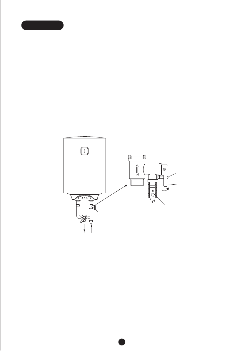
The pressure relief valve attached with the heater must be installed at the cold water inlet of this
heater(see Fig.1), and make sure it is not exposed in the foggy. The water may be outflowed from
pressure relief valve, so the outflow pipe must open wide in the air; The pressure relief valve
need to be checked and cleaned regularly, so as to make sure it will not be blocked.
Thread screw
Drain handle
Pressure
relief valve
Hot water
●
When using the heater for the first time(or the first use after maintenance), the heater can not be
switched on until it has been filled fully with water. When filling the water, at least one of the outlet
valves at the outlet of the heater must be opened to exhaust the air. This valve can be closed
after the heater has been filled fully with water.
●
The water heater is not intended for use by persons(including children)with reduced physical,
sensory or mental capabilities, or lack of experience and knowledge, unless they have been
given supervision or instructions concerning use of the appliance by a person responsible for
their safety. Children should be supervised to ensure that they do not play with the heater.
●
During heating, there may be drops of water dripping from the pressure release hole of the
pressure relief valve. This is a normal phenomenon. If there is a large amount of water leak,
please contact customer care center for repair. This pressure release hole shall, under no
circumstances, be blocked; otherwise, the heater may be damaged, even resulting in accidents.
●
The drainage pipe connected to the pressure release hole must be kept sloping downwards.
●
Since the water temperature inside the heater can reach up to 75℃, the hot water must not be
exposed to human bodies when it is initially used. Adjust the water temperature to a suitable
temperature to avoid scalding.
●
If the flexible power supply cord is damaged, the special supply cord provided by the manufacturer
must be selected, and replaced by the professional maintenance personnel.
Cold water
Pressure release hole
(Fig.1)
2
Page 4

●
If any parts and components of this electrical water heater are damaged please contact customer
care center for repair.
●
This appliance is not intended for use by persons (including children) with reduced physical,
sensory or mental capabilities, or lack of experience and knowledge, unless they have been
given supervision or instruction concerning use of the appliance by a person responsible for
their safety.
●
Children should be supervised to ensure that they do not play with the appliance.
●
The maximum inlet water pressure is 0.5MPa; the minimum inlet water pressure is 0.1MPa, if this
is necessary for the correct operation of the appliance.
●
The water may drip from the discharge pipe of the pressure-relief device and that this pipe must
be left open to the atmosphere; The pressure-relief device is to be operated regularly to remove
lime deposits and to verify that it is not blocked.
●
In order to drain away the water inside the inner container, it can be drained away from the
pressure release valve. Twist the thread screw of the pressure release valve off, and lift the drain
handle upwards.(See Fig.1) A discharge pipe connected to the pressure-relief device is to be
installed in a continuously downward direction and in a frost-free environment.
2. PRODUCT INTRODUCTION
2.1 Nomenclature
D -
�
�
�
is the product code of the storage electric water heater;
�
is the capacity (L);
�
represents the rated power (*100W);
���
represents the pattern code (eg : A,B,C...);
represents the extension of pattern (eg : 1,2,3...);
�
�
NOTE
This manual is applicable to the storage electric water heaters (D *-***) manufactured by
this company.
2.2 Technical Performance Parameters
Model
D30-20Z1
D50-20Z2
Volume
(L)
30
50
Rated
Power
(W)
2000
Rated
Voltage
(ACV)
220-2402000
220-240
220-240
220-240
Rated
Pressure
(MPa)
0.75
0.75
3
Max Of Water
Temperature
(℃)
75
75
Protection
Class
I
I
I
I
Waterproof
Grade
IPX4
IPX4
IPX4750.75200080D80-20Z3
IPX4750.752000100D100-20Z3
Page 5

2.3 Brief introduction of product structure
A
Thermometer
Inner tank
Thermal
insulation
B
On/ Off
Power
indicator
light
Hot water outlet
2.4 Internal Wire Diagram
Temperature
adjusting knob
Cold water inlet
Heating indicator light
D30-20Z1
A
B
C
D
340
576
340
200
C
Shell
Heating
element
Anode
D50-20Z2
385
710
385
200
D80-20Z3
450
745
450
200
(Note:All dimensions are in mm)
D
D100-20Z3
450
890
450
200
Brown
L
Blue
N
Yellow/Green
E
Thermal
Cut Out
Thermostat
Power Supply
Indicator Light
Switch
WIRING DIAGRAM
4
Heating Element
Heating Indicator light
Page 6

3. UNIT INSTALLATION
3.1 Installation Instruction
This electrical water heater shall be installed on a solid wall. If the strength of the wall cannot
�
bear the load equal to two times of the total weight of the heater filled fully with water, it is
then necessary to install a special support.
Incase of hollow bricks wall, ensure to fill it with cement concrete completely.
After selecting a proper location, determine the positons of the two install holes used for
�
expansion bolts with hook, Make two holes in the wall with the corresponding depth by using
a chopping bit with the size matching the expansion bolts attached with the machine, insert
the screws, make the hook upwards, tighten the nuts to fix firmly, and then hang the electrical water heater on it (see Fig.2).
Expansion bolt (with hook)
Install the supply socket in the wall. The requirements for the socket are as follows: 250V/10A,
�
single phase, three electrodes. It is recommended to placed the socket on the right above
the heater. The height of the socket to the ground shall not be less than 1.8m (see Fig.3). If
there is fault on power cable, it should be replaced by the manufacturers, agencies or qualified
person who is able to do this so as to ensure the safety.
(Fig.2)
L (Brown)
If the bathroom is too small, the heater can be installed at another place. However, in order
�
to reduce the pipeline heat losses, the installation position of the heater shall be closed to
the location shall be as near as possible to the heater.
E (Yellow/Green)
N (Blue)
≥1.8m
Ground
(Fig.3)
5
Page 7

3.2 Pipelines Connection
�
The dimension of each pipe part is G1/2” ; The massive pressure of inlet should use Pa as
the unit; The minimum pressure of inlet should use Pa as the unit.
�
Connection of pressure relief valve with the heater on the inlet of the water heater.
In order to avoid leakage when connecting the pipelines, the rubber seal gaskets provided with
�
the heater must be added at the end of the threads to ensure leak proof joints (see Fig.4).
Power cord
Hot water outlet
Rubber seal gaskets
Screw for hot water outlet
Adjusting handle for
mixing valve
�
If the users want to realize a multi-way supply system, refer to the method shown in fig.5
and fig.6 for connection of the pipelines.
Triple joint
Water pool
Shower nozzle
Hot
water
outlet
Mixing valve
Cold water inlet
Rubber seal gaskets
Pressure relief valve
Pressure release hole
Joint screw for cold water inlet
Power cord
Main machine
Pressure relief valve
Cold
water
inlet
Water inlet valve
Shower nozzle
Water inlet valve
Running water pipe
(Fig.4)
(Fig.5)
6
Page 8

NOTE
Please be sure to use the accessories provided by our company to install this electric
water heater. This electric water heater can not be hung on the support until it has been
confirmed to be firm and reliable. Otherwise, the electric water heater may drop off from
the wall, resulting in damage of the heater, even serious accidents of injury. When
determining the locations of the bolt holes, it shall be ensured that there is a clearance
not less than 0.2m on the right side of the electric heater, to convenient the maintenance
of the heater, if necessary.
4. METHODS OF USING
●
First, open any one of the outlet valves at the outlet of the water heater, then, open the inlet
valve. The water heater gets filled with water. When water flows out of the outlet pipe it implies
that the heater has been filled fully with water, and the outlet valve can be closed.
NOTE
During normal operation, the inlet valve shall be always kept open.
Insert the supply plug into the supply socket, the indicator will light up this time.
●
The thermostat will automatically control the temperature. When the water temperature inside
●
the heater has reached the set temperature, it will switch off automatically, when the water
temperature falls below the set point the heater will be turned on automatically to restore the
heating.
5. MAINTENANCE
!
Before doing any maintenance, please cut off the power supply.
●
Check the power plug and outlet as often as possible. Secure electrical contact and also proper
grounding must be provided. The plug and outlet must not heat excessively.
●
If the heater is not used for a long time, especially in regions with low air temperature(below 0℃),
it is nessary to drain water from the heater to prevent damage of the water heater, due to water
freezing in the internal tank.(Refer Cautions in this manual for the method to drain away the water
from the inner container).
●
To ensure long reliable water heater operation, it is recommended to regularly clean the internal
tank and remove deposits on the electric heating element of the water heater, as well as check
condition (fully decomposed or not) of the magnesium anode and, if necessary, replace it with a
new one in case of full decomposition.Tank cleaning frequency depends on hardness of water
located in this territory. Cleaning must be performed by special maintenance services. You can
ask the seller for address of the nearest service center.
WARNING
7
Page 9

●
The water heater is equipped with a thermal switch, which cuts off power supply of the heating element
upon water overheating or its absence in the water heater. If the water heater is connected to the mains,
but water is not heated and the indicator doesn’t light up, then the thermal switch was switched off or not
switched on. To reset the water heater to the operating condition, it is necessary to:
1. De-energize the water heater, remove the plate of the side/lower cover.
2. Press the button, located at the center of the thermal switch, see Fig.6;
3. If the button is not pressed and there is no clicking, then you should wait until the thermal switch
cools down to the initial temperature.
Manual reset button
(Fig.6)
!
Non-professionals are not allowed to disassemble the thermal switch to reset.
Please contact prefessionals to maintain. Otherwise our company will not take
responsiblity if any quality accident happens because of this.
6. TROUBLESHOOTING
WARNING
NOTE
This products are not equipped with plug. Please contact prefessionals to purchase and
install plug. Parts illustrated in this use and care manual are indicative only, parts provided
with the product may differ with illustrations.This product is intended for household use only.
Specifications are subject to change without notice.
8
Page 10

www.beko.com
 Loading...