

Page 1
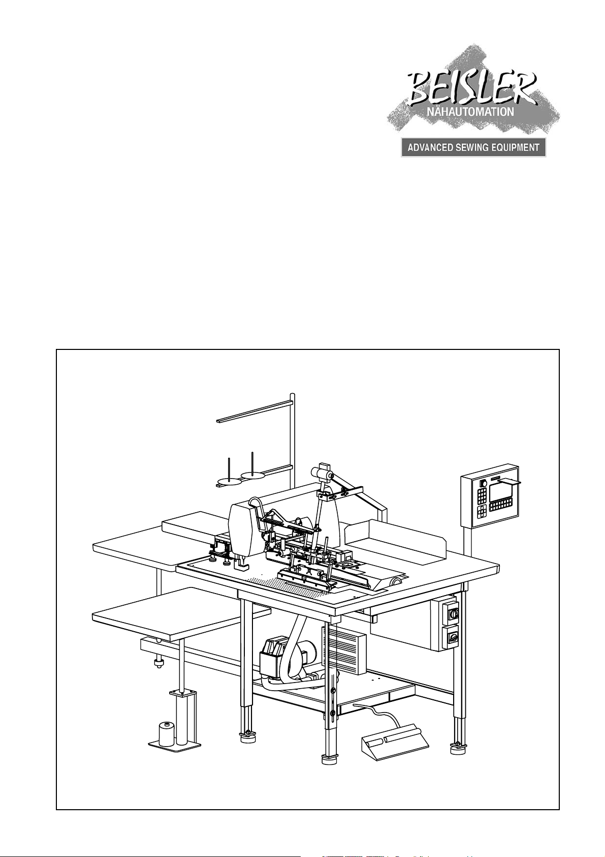
Short Seam Automat 2112-4 Working Instructions
Beisler Automated Sewing Equipment
Working Instructions
Short Seam Automat 2112-4
- A 1 -
Page 2

Beisler Automated Sewing Equipment
Contents of the working instructions
The working instructions are divided into four sections:
A General notes: page A 1 - A 10
Safety instructions for the operating and service personnel and for the operator
of the machine.
B Operating instructions: page B 11 - B 36
Instructions for the personnel operating and handling the machine.
C Service instructions: page C 37 - C 68
Instructions for the personnel in charge of the initial start-up, setting up and
service of the machine.
Short Seam Automat 2112-4 Working Instructions
D Programming instructions: page D 69 - D 102
Instructions for the service personnel in charge of preparing and setting up the
machine.
Scope of the working instructions
These working instructions describe the SHORT SEAM AUTOMAT 2112-4 of Beisler
GmbH and apply only to those machine parts and components that are contained in the
scope of delivery of the SHORT SEAM AUTOMAT 2112-4.
They do not apply to accessories or machine parts (e.g. sewing head) from third parties
that the machine is equipped or retrofitted with. For those components, the working
instructions of the respective manufacturer or supplier apply.
- A 2 -
Page 3

Short Seam Automat 2112-4 Working Instructions
Beisler Automated Sewing Equipment
Section A
General notes
- A 3 -
Page 4

Beisler Automated Sewing Equipment
Short Seam Automat 2112-4 Working Instructions
General notes
Section A
Contents
A.1 Safety instructions ............................................................................................................... 5
A.1.1 Symbols used in the working instructions ...................................................................... 8
A.1.2 Symbols used on the machine ....................................................................................... 8
A.1.3 General safety instructions ............................................................................................ 9
A.2 Notices ............................................................................................................................... 10
- A 4 -
Page 5

Short Seam Automat 2112-4 Working Instructions
Safety instructions
A.1
Important information for the operator!
This machine has been manufactured in keeping with the latest technological developments and is operationally safe. However, it may present potential hazards, particularly
if it is operated by inadequately trained personnel or if it is not used correctly:
• For personnel operating and handling the machine, the operator must prepare written
instructions in a reasonable form and in the language of the operating personnel based
on these working instructions (Germany: Accident Prevention Regulations UVV VBG
1 § 7.2).
• Use the operating instructions to familiarize the operating personnel with the functions,
operation, and care of the machine and check to see if the operating personnel fully
understands these instructions.
• Use the service instructions to familiarize the service personnel with the setting up
and maintenance of the machine.
• For any modifications of the machine that have not been approved by Beisler GmbH
in writing, the operator is fully responsible.
• The contents of the working instructions are subject to change without further notice.
• Concerning translations into foreign languages, the German version of these working
instructions is binding.
• Should you encounter problems that are not mentioned in these working instructions,
please contact your supplier immediately for your own safety. Please do not hesitate
to contact Beisler if you have any suggestions that help to improve this product.
• Keep these working instructions close to the machine so that safety instructions
and information on operation, setting-up, and maintenance are always accessible.
Beisler Automated Sewing Equipment
Warranty
Beisler GmbH warrants the safety, operatability, and repair without charge of the short
seam automat 2112-4 for a period of 6 months under the condition that:
• the machine is used exclusively for the intended purpose and serviced in accordance
with the information in these working instructions,
• modifications of the machine are carried out only with prior written approval of Beisler
GmbH,
• only original spare parts or accessories approved by Beisler GmbH are used. For a
complete list of all approved spare parts, please contact Beisler GmbH.
If the machine is used for more than 10 hours per day (shift operation), the warranty period
is reduced to 3 months.
The warranty period starts with the delivery of the machine to the operator.
- A 5 -
Page 6

Beisler Automated Sewing Equipment
Safety instructions
A.1
Exclusion of liability
Beisler GmbH warrants the faultlessness of the product as set forth by their
advertisement, product information and these working instructions. Other product
characteristics are not warranted.
Beisler GmbH is not responsible for the profitability or for the correct function of
the short seam automat 2112-4 if it is used for other purposes than those defined
in section „Correct use“.
Beisler GmbH is not responsible for damage that arises from the use of non-defined
and non-approved spare parts or accessories.
Copyright
© 2005 Beisler GmbH, Hösbach, 07/2005
Short seam automat
The short seam automat 2112-4 and all related parts are protected by copyright.
Any reproduction of the machine will be prosecuted.
Short Seam Automat 2112-4 Working Instructions
Working instructions
These working instructions are protected by copyright. No part of the working instructions, including figures and tables, may be reproduced or translated in any
form or by any means, electronic or mechanical, without the express written permisson of Beisler GmbH.
Beisler GmbH
Fohnradstr. 10
63768 Hösbach
Germany
Phone: ++ 49 / 6021 / 50 19 0
Fax: ++ 49 / 6021 / 50 19 10
eMail: [email protected]
- A 6 -
Page 7

Short Seam Automat 2112-4 Working Instructions
Safety instructions
A.1
Important information for the operating personnel!
Please note that any work to the SHORT SEAM AUTOMAT 2112-4 must be carried out
only by trained operating personnel:
• Operating personnel means persons:
that have been given initial instructions for sewing automats and that
have been trained for the operation and handling of the SHORT SEAM
AUTOMAT 2112-4 on the basis of these operating instructions,
that have been informed about potential risks arising from their work
with the machine,
that are capable of assessing their work with the machine due to occupational experience and instruction of the safety regulations and of
recognizing potential hazards during work.
• Cleaning of the machine or of machine parts must be performed only by personnel
that has been informed about potential hazards arising during the cleaning work.
• Prior to the initial operation of the SHORT SEAM AUTOMAT 2112-4, read the ope-
rating instructions carefully so that you can make full use of the advantages of the
machine and to prevent damage.
Beisler Automated Sewing Equipment
Important information for the service personnel!
Please note that service work to the SHORT SEAM AUTOMAT 2112-4 must be carried
out only by authorized and adequately trained expert personnel:
• Expert personnel means persons:
that have aquired their expertise by a special training in machine technology or electrical engineering or by a special advanced training or a
comparable qualification,
that have acquired the knowledge required to perform all works for setting up and servicing the SHORT SEAM AUTOMAT 2112-4 from a training
by Beisler GmbH,
that are capable of assessing their work with the machine due to occupational experience and instruction of the safety regulations and of
recognizing potential hazards during work.
• Prior to carrying out any service work to the SHORT SEAM AUTOMAT 2112-4, read
the entire working instructions carefully so that you can make full use of the advantages of the machine and to prevent damage.
- A 7 -
Page 8
Beisler Automated Sewing Equipment
Safety instructions
A.1
Short Seam Automat 2112-4 Working Instructions
A.1.1 Symbols used in the working instructions
WARNING!
is used if non-observance may cause serious or even lethal
injuries.
CAUTION!
is used if non-observance may cause medium to minor
injuries or damage.
NOTE!
is used for hints and useful information.
A.1.2 Symbols used on the machine
WARNING: DANGER!
Caution! Observe working instructions.
WARNING: HIGH VOLTAGE!
Caution! Prior to opening, pull out power plug.
- A 8 -
Page 9

Short Seam Automat 2112-4 Working Instructions
Safety instructions
A.1
A.1.3 General safety instructions
Beisler Automated Sewing Equipment
Correct use
• The SHORT SEAM AUTOMAT 2112-4 is a sewing
machine. It is to be used for:
• Crimping over and tucking of pocket edges.
• Clipping the slash selvage and sewing the slash
selvage to the left trousers component.
• Sewing the slash selvage to the right trousers component.
• The maximum length of the pocket edge to be processed is 300 mm. If the machine is equipped with an
optional, oversized crimping over and insertion station,
the maximum length of the pocket edge to be processed is 400 mm.
• The machine can be used for processing all conventional materials for outerwear.
• The machine has been designed for permanent operation in industry.
• The SHORT SEAM AUTOMAT 2112-4 has been tested
for electromagnetic compatibility and is suited for installation in industrial operating rooms.
Incorrect use
• The SHORT SEAM AUTOMAT 2112-4 must not be
operated in rooms that do not comply with the location
requirements.
• The SHORT SEAM AUTOMAT 2112-4 must not be
operated in the vicinity if devices or systems that produce strong magnetic fields as otherwise the correct
function of the program control may be impaired.
Safety requirements
• DIN EN, Part 1:1991-11, Part 2:1995-06
Safety of machines
• DIN EN 60601, Part 1:1994-05
Safety regulations for electrically operated measuring
and control installations, general requirements.
• DIN EN 50178 (VDE 0160): 1998-04
Equipment of power systems with electronic devices
• DIN EN 50082 (VDE 0839) Part 2:1997-11
Electromagnetic compatibility, basic specification,
immunity to interference.
Part 1: Domestic, business and commerce, small
enterprises.
Part 2: Industry.
• DIN EN 60204 (DIN VDE 0113): 1993-06
Electrical equipment of industrial machines
Safety devices
The SHORT SEAM AUTOMAT 2112-4 is equipped with a
circuit-breaker (program stop switch) that stops all ma-
chine movements and the sewing process when actuated
manually.
Power supply connection
The power supply of the machine is established with a
properly grounded power supply connection with:
• 230 V ± 10 %, 50/60 Hz, grounding plug.
• Fusing: 16 A
• Power consumption: 1.3 kW
Compressed air supply
The machine must be supplied by an on-site compressed
air source.
• Operating pressure: 6 bar.
• Compressed air quality: oil-free
• Compressed air consumption: 12 NL
Location and storage requirements
Installation in sheltered, closed rooms.
• Room temperature: +10 °C to 45 °C
• Relative humidity: 80 % max.
Disposal
• Please discard the packaging material in accordance
with existing disposal directives. Section C1, Delivery
of the machine, contains a list of the packaging materials used.
• The machine contains reusable materials. Therefore,
when discarding the machine, ask your local magistrate or community office about the possibilities of
recycling.
- A 9 -
Page 10

Beisler Automated Sewing Equipment
Notices
A.2
Short Seam Automat 2112-4 Working Instructions
- A 10 -
Page 11

Short Seam Automat 2112-4 Working Instructions
Beisler Automated Sewing Equipment
Section B
Operating Instructions
- B 11 -
Page 12

Beisler Automated Sewing Equipment
Short Seam Automat 2112-4 Working Instructions
Operating Instructions
Section B
Contents
B.1 Description of the machine .............................................................................................. 13
B.1.1 Functional units ...........................................................................................................13
B.2 Functions of the machine................................................................................................. 14
B.2.1 Sewing functions of the machine ................................................................................ 14
B.2.2 Pocket edge function .................................................................................................. 14
B.2.3 Lining up pocket edge/pocket bag .............................................................................. 14
B.2.4 Sewing of pocket edge/pocket bag ............................................................................. 16
B.2.5 Left slash selvage ....................................................................................................... 17
B.2.6 Lining up the left slash selvage ................................................................................... 17
B.2.7 Sewing the left trousers component ........................................................................... 19
B.2.8 Right slash selvage ..................................................................................................... 21
B.2.9 Right slash selvage/trousers component line-up ....................................................... 21
B.2.10 Sewing the right trousers component .........................................................................22
B.2.11 Switches ......................................................................................................................23
B.2.12 Operating panel ...........................................................................................................24
B.3 Operation............................................................................................................................ 25
B.3.1 Safety instructions for operation ................................................................................. 25
B.3.2 Preparing the machine ................................................................................................26
B.3.3 Selecting the sewing program .................................................................................... 27
B.3.4 Activating additional seam numbers ...........................................................................28
B.3.6 Setting the thread clamp manually ............................................................................. 28
B.3.7 Operating the stacker .................................................................................................. 28
B.3.8 Testing the cutters ....................................................................................................... 29
B.3.9 Resetting the day counter to zero ............................................................................... 29
B.3.10 Quick stitch width setting ............................................................................................ 30
B.3.11 Controlling machine cycle ........................................................................................... 31
B.3.12 Pocket edge start mode ..............................................................................................33
B.3.13 Start mode "Left slash selvage" .................................................................................. 35
B.3.16 Moving machine to zero position ................................................................................ 36
B.3.17 Stopping a sewing program ........................................................................................ 36
B.3.18 Turning the machine off .............................................................................................. 36
B.3.19 Periodic cleaning of the machine ................................................................................ 36
- B 12 -
Page 13
Short Seam Automat 2112-4 Working Instructions
Description of the machine
B.1
Beisler Automated Sewing Equipment
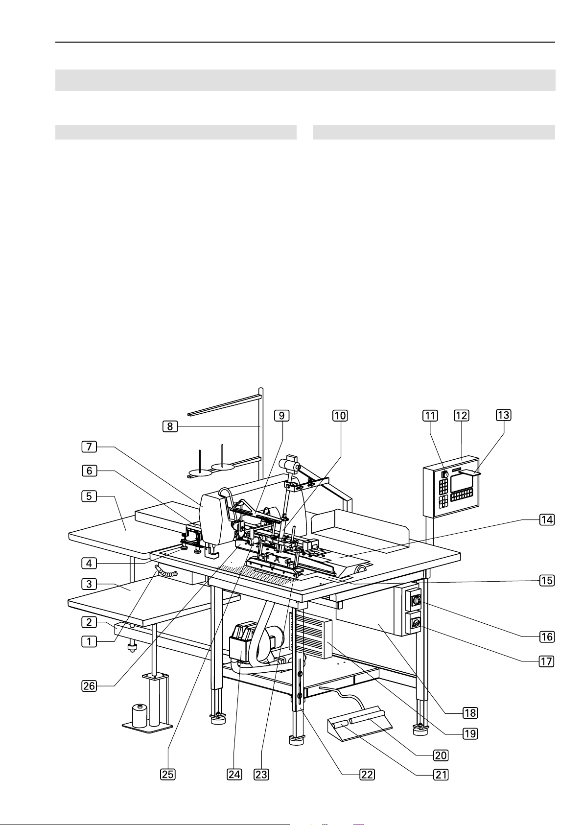
B.1.1 Functional units
All functional units of the SHORT SEAM AUTOMAT
2112-4 are mounted to the height-adjustable table frame
and freely accessible.
Transport and sewing unit
q
Main clamp
2
Stacker, with sliding table 5 and
lift table
4
Transport stampl
6
Linear rail (under the cover)
7
Sewing head
8
Thread holder
9
Right slash selvage stop
a
Folder with quick stitch width setting
e
Pick-up plate
f
Pocket bag clamp
p
Guide laser
Fig. 1
3
Control unit
c
Operating panel
d
Memory-Card
Worktable
m
Height-adjustable table leg
n
Working plate
Emergency switch
b
Program stop switch
Power supply system
g
Main switch, emergency off switch
h
Vacuum pump power supply switch
i
Control box
j
Sewing motor control
Operating switches
k
Footswitch for machine operation
l
Footswitch for slash selvage clamp
Compressed air / Vacuum supply system
o
Vacuum pump (optional)
1
Compressed air device
Fig. 1
- B 13 -
Page 14
Beisler Automated Sewing Equipment
Functions of the machine
B.2
Short Seam Automat 2112-4 Working Instructions
B.2.1 Sewing functions of the machine
The short seam automat 2112-4 can perform three different, automated sewing functions:
• Crimping over of the pocket edge and sewing the pokket edge to a pocket bag.
• Clipping and crimping over of the left slash selvage with
subsequent sewing of the slash selvage to the left trousers component.
• Sewing the slash selvage to the right trousers component.
B.2.2 Pocket edge function
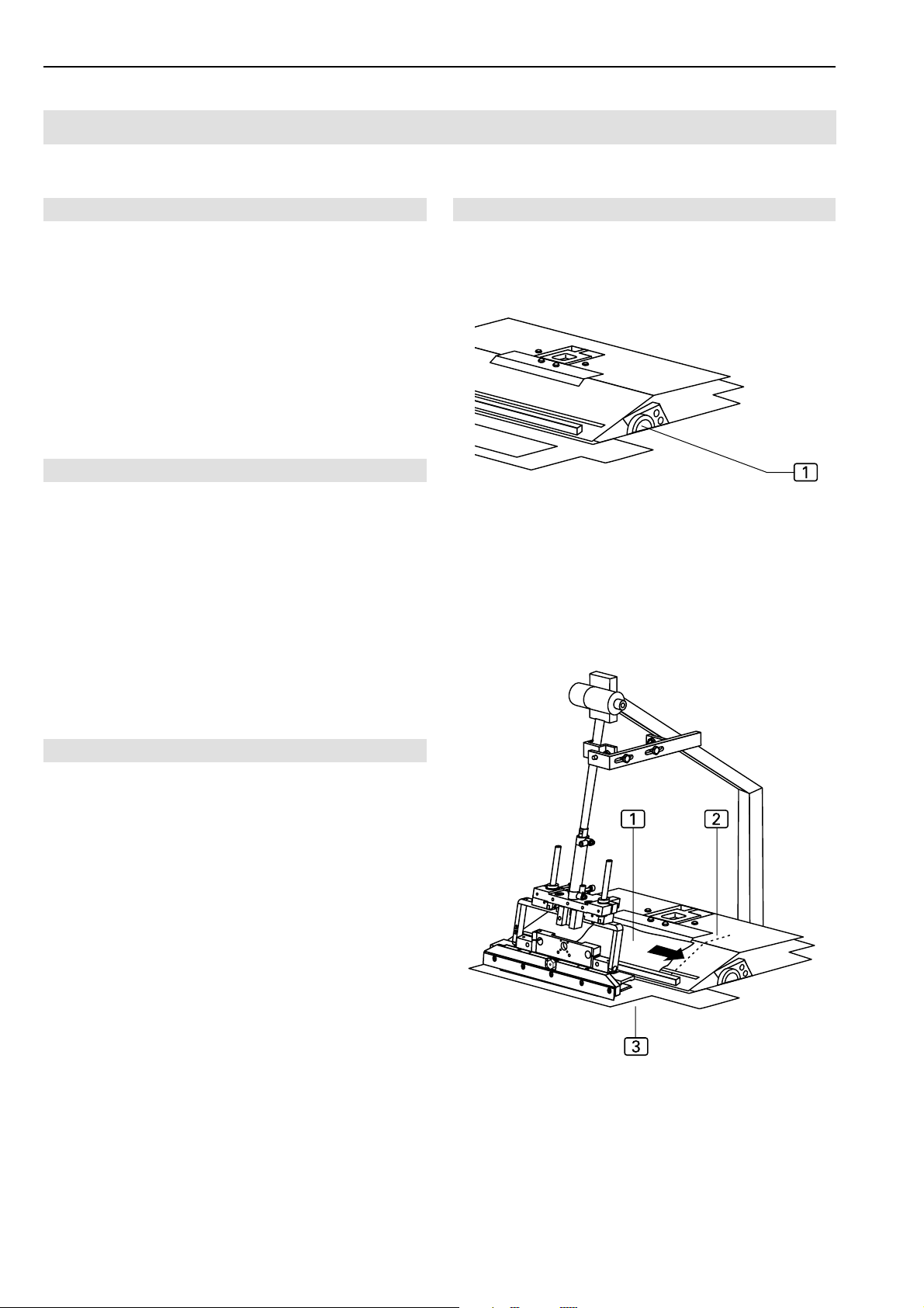
The machine cycle "Sewing on pocket edge" is performed
as follows:
• Pocket edge and pocket bag are positioned manually.
• The pocket edge is crimped over and picked up.
• The folder transports the pocket edge to the pocket bag.
• The transport system automatically transports the pokket edge and the pocket bag to the sewing head where
they are tucked.
• The finished piece is transported to the stacking table
by the stacking system and put down.
Fig. 2/3
Fig. 2
Fig. 3
B.2.3 Lining up pocket edge/pocket bag
Depending on how the pocket edge and the pocket bag
are to be sewn to one another, the two pieces must be aligned at the line-up positions. The exact line-up position
of the edge to the bag can be marked at the working plate
or at the pick-up plate using tape or pen. Please note that
the pocket bag must be lined up within the operating range
of the pocket bag clamp (Fig. 3, 4).
Handwheel for stitch width, Fig. 2:
The handwheel 1 is used to set the correct stitch width
for the pocket edge. The stitch width depends on the
thickness of the fabric. The thicker the fabric, the larger the stitch width.
Line-up position for pocket edge, Fig. 3:
The pocket edge 1 is lined up at the stop rail 3 of
the pick-up plate. The exact alignment to the pocket
bag is marked by a marking 2 at the pick-up plate.
- B 14 -
Page 15

Short Seam Automat 2112-4 Working Instructions
Functions of the machine
B.2
Beisler Automated Sewing Equipment
B.2.3 Lining up pocket edge/pocket bag
Crimping over and picking up pocket edge, Fig. 4:
The folder 1 moves to the right to the pick-up
plate5. The pocket edge is crimped over and picked
up. During this time, the pocket bag is positioned.
Pocket bag line-up position, Fig. 4:
The pocket bag 3 is lined up within the operating range of the pocket bag clamp 2. The exact position is
determined by a marking 4 at the working plate.
Fig. 4
Fig. 4
- B 15 -
Page 16
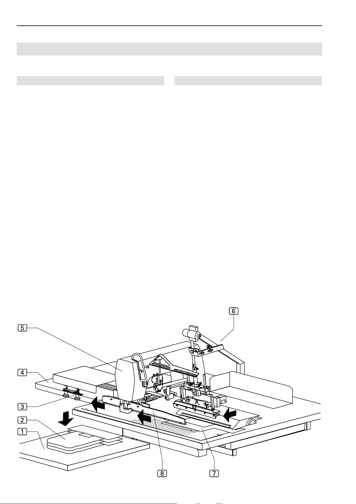
Beisler Automated Sewing Equipment
Functions of the machine
B.2
Short Seam Automat 2112-4 Working Instructions
B.2.4 Sewing of pocket edge/pocket bag
Folder
The folder 6 moves to the left with the pocket edge,
is lowered and puts the pocket edge onto the pocket
bag.
Pocket bag clamp
The pocket bag clamp 7 fixes the pocket bag to the
working plate until the main clamp picks up the sewing
pieces and transports them to the sewing head. The
pocket bag clamp closes while the folder moves to the
left.
Main clamp
The main clamp 8 moves to the inserting station and
picks up the sewing pieces. The folder moves back up
to its start position.
The main clamp pushes the sewing piece on the working plate from the inserting station to the sewing head.
Fig. 5
Fig. 5
Sewing head
The sewing head 5 performs only the functions sewing stitch and thread cutting. All other functions, such
as seam length or determining the beginning and the
end of the seam, are acquired by the sensor system
and controlled by the program control unit in accordance with the set values.
The thread stock and the thread supply of the sewing
head are monitored by sensors (top thread monitor and
spool residual thread monitor).
The thread holder can hold two thread spools.
Transport stamp
After tucking, the sewing piece is blown even and transferred by the transport stamp 3 to the stacker.
Stacker
The stacker consists of a sliding table 4 and a
lift table 1.
The sewing pieces are put down on the sliding table
of the stacker. The sliding table then moves backward,
and the sewing pieces 2 fall onto the lift table where they are stacked.
The lift table is lowered automatically (photocell control) or is lowered in preset steps in accordance with
the input numbers.
- B 16 -
Page 17
Short Seam Automat 2112-4 Working Instructions
Functions of the machine
B.2
Beisler Automated Sewing Equipment
B.2.5 Left slash selvage
The machine cycle "Clipping left slash selvage and sewing
it to the left trousers component" is performed as follows:
• The left slash selvage is lined up manually at the pickup plate.
• The slash selvage is clipped, crimped over by the folder
and picked up.
• The left trousers component is positioned manually on
the working plate.
The folder transports the slash selvage to the left trousers component and puts it down.
• The trousers component with the slash selvage is automatically transported by the transport system to the
sewing head where it is tucked.
• The finished sewing piece is then blown off the worktable with compressed air.
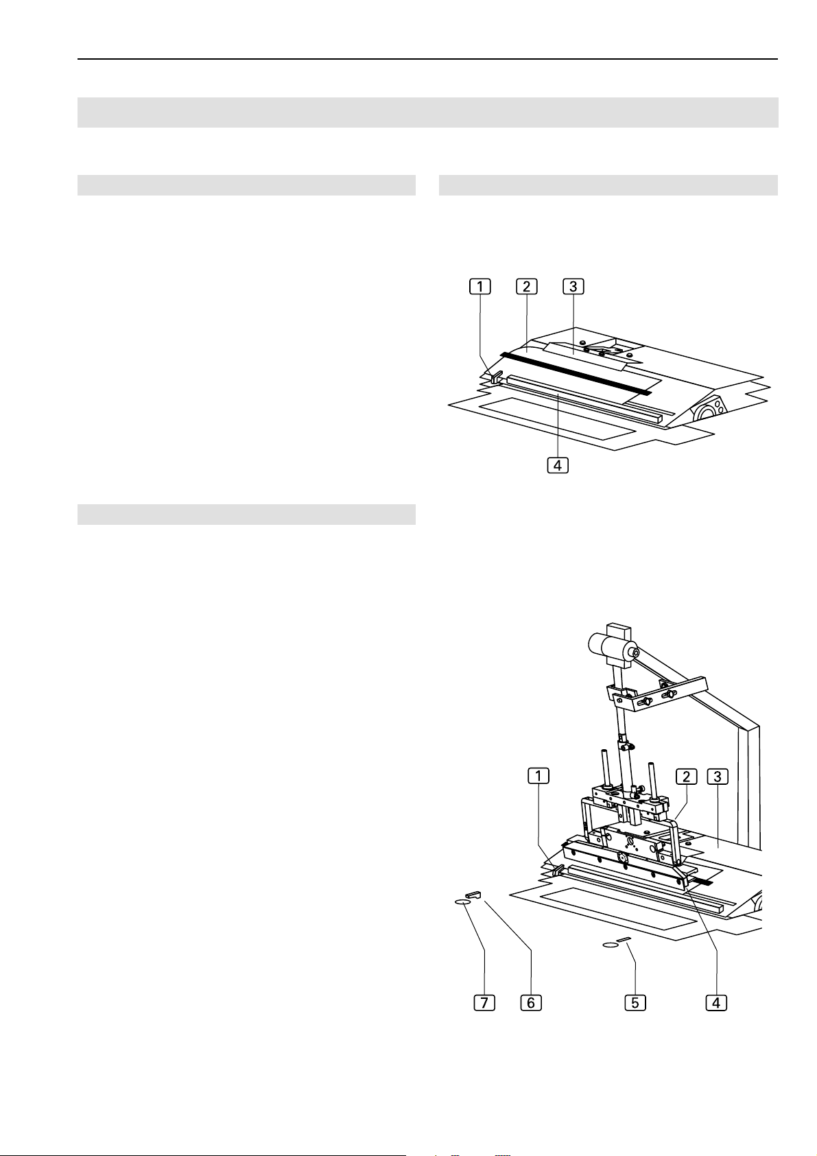
B.2.6 Lining up the left slash selvage
Ideally, the slash selvage and the left trousers component
are premarked by a gusset. If a gusset is not available,
the line-up position is marked with tape or with a felt pen
at the working plate or at the pick-up plate.
Fig. 6/7
Fig. 6
Fig. 7
Slash selvage line-up position, Fig. 6:
The slash selvage clamp 3 is open during the lineup process.
The slash selvage 2 is lined up at the stop rail 4 of
the pick-up plate. The exact position to the cutter
is marked by the gusset in the slash selvage.
Slash selvage clamp, Fig. 6:
The slash selvage clamp 3 closes and secures the
slash selvage while the cloth material is clipped and
then crimped over.
Crimping over and picking up the slash selvage, Fig. 7:
The folder 2 moves right to the pick-up plate 3. The
slash selvage is clipped by the cutter 1 and then crimped over and picked up by the folder clamp 4.
The left, rear cutter 6 of the working plate opens, the
front cutter 5 is passive and remains concealed in the
working plate.
The light of the positioning lamp 7 supports the lining up of the gusset of the left trousers part to the
cutter6.
1
- B 17 -
Page 18
Beisler Automated Sewing Equipment
Functions of the machine
B.2
Short Seam Automat 2112-4 Working Instructions
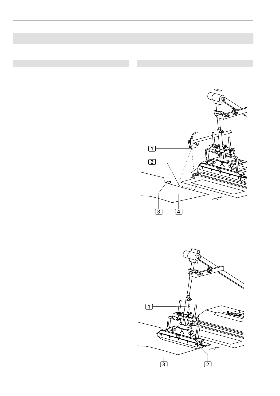
Fig. 8/7
Line-up position of the left trousers component, Fig. 8:
The left trousers component 4 is lined up with the
gusset to the cutter 3 and parallel to the red marking
line2 of the guide laser 1.
Folder, Fig. 9:
The folder 1 moves left to the working plate with the
slash selvage, lowers and puts the slash selvage
onto the left trousers component 3.
2
Fig. 8
Fig. 9
- B 18 -
Page 19

Short Seam Automat 2112-4 Working Instructions
Functions of the machine
B.2
Beisler Automated Sewing Equipment
B.2.7 Sewing the left trousers component
Main clamp, Fig. 10:
The main clamp 2 moves to the insertion position and
picks up the trousers component. The folder moves up
to its start position.
The main clamp transports the trousers component on
the working plate from the insertion station to the sewing head.
Sewing head, Fig. 10:
The sewing head 1 only performs the sewing stitch
and thread cutting functions. All other functions, such
as seam length or setting the beginning and the end
of the seam, are acquired by the machine's sensoring
system and controlled by the program control in accordance with the set values.
Fig. 10
Threads
Thread stock and thread supply of the sewing head are
monitored by sensors (top thread sensor and rest
thread sensor).
The thread holder can hold two thread spools.
Blow-off, Fig. 10:
After the sewing process, the trousers component
is blown off the worktable with compressed air.
Fig.10
3
- B 19 -
Page 20
Beisler Automated Sewing Equipment
Functions of the machine
B.2
Short Seam Automat 2112-4 Working Instructions
B.2.8 Right slash selvage
The machine cycle "Sewing the right slash selvage to the
right trousers component" is performed as follows:
• The right trousers component is positioned manually
on the working plate.
• The trousers component is clipped, the stop for the
slash selvage swivels onto the working plate.
• The right slash selvage is lined up manually at the stop.
• The trousers component with the slash selvage is transported automatically to the sewing head where it is
tucked.
• The finished sewing piece is then blown off the working table with compressed air.
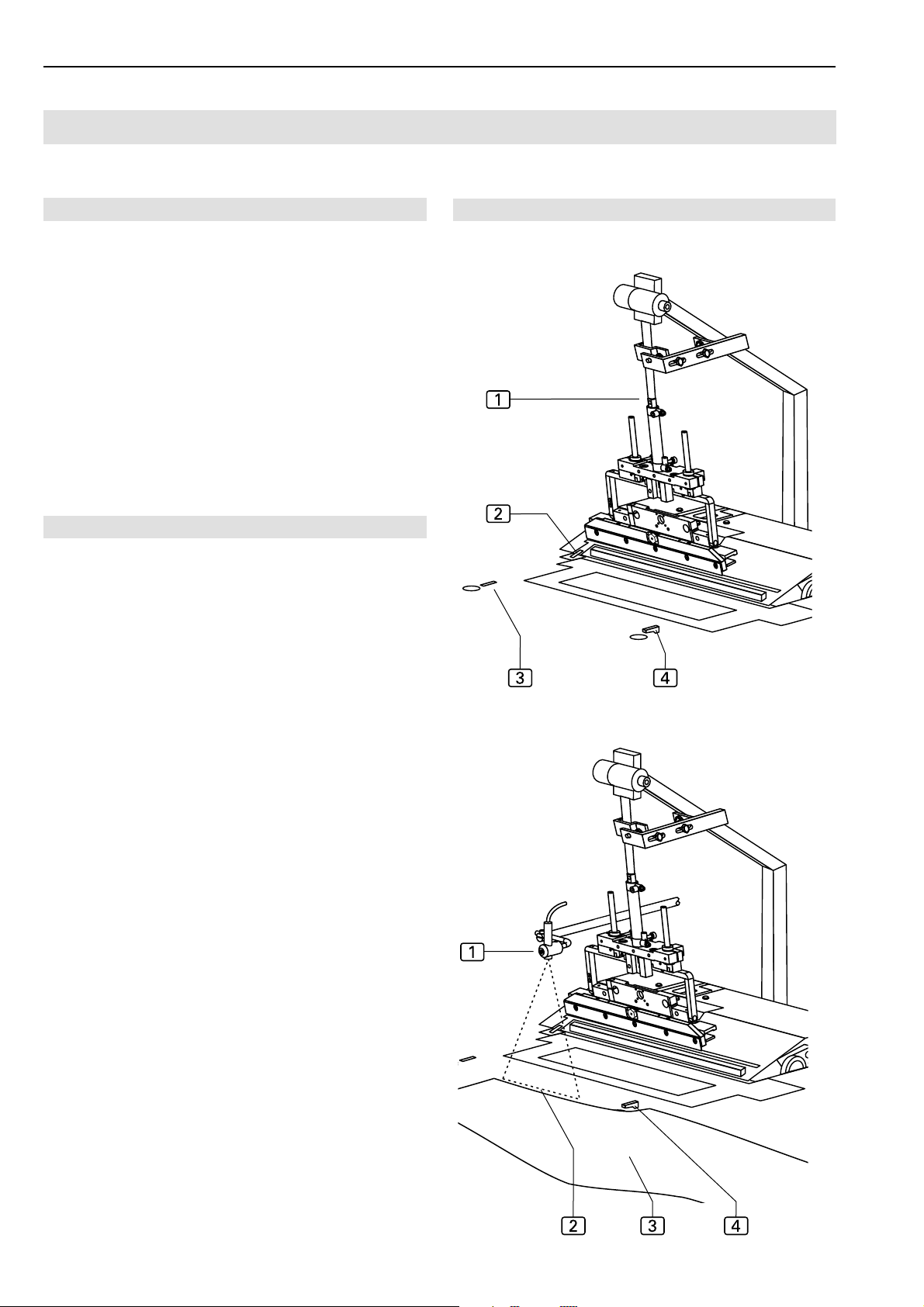
B.2.9 Right slash selvage/trousers component line-up
Ideally, the right trousers component is premarked by a
gusset. If a gusset is not available, the line-up position is
marked with tape or with a felt pen at the working plate
or at the pick-up plate.
Fig.11/12
Fig. 11
Folder, Fig. 11:
The folder 1 moves right to the pick-up plate and
makes the working plate accessible. The front cutter
4
opens, the two rear cutters 2 and 3 are passi-
ve and remain concealed in the working plate.
Right trousers component line-up position, Fig. 12:
The right trousers component 3 is aligned with the
gusset at the front cutter 4 and parallel to the pickup plate and the folder at the red marking 2 of the guide laser 1.
Fig. 12
- B 20 -
Page 21
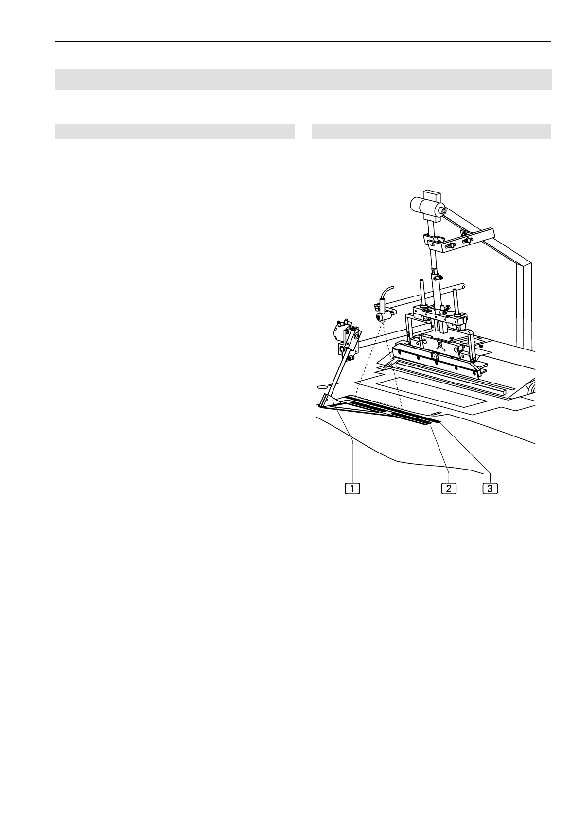
Short Seam Automat 2112-4 Working Instructions
Functions of the machine
B.2
Beisler Automated Sewing Equipment
Fig. 13
Stop, Fig. 13:
After the cutter has clipped, the stop 1 swivels to the
right trousers component.
Line-up position of the right slash selvage, Fig. 13:
The right slash selvage 3 is lined up immediately at
the stop rail 2 and flush with the right trousers component.
Fig. 13
- B 21 -
Page 22
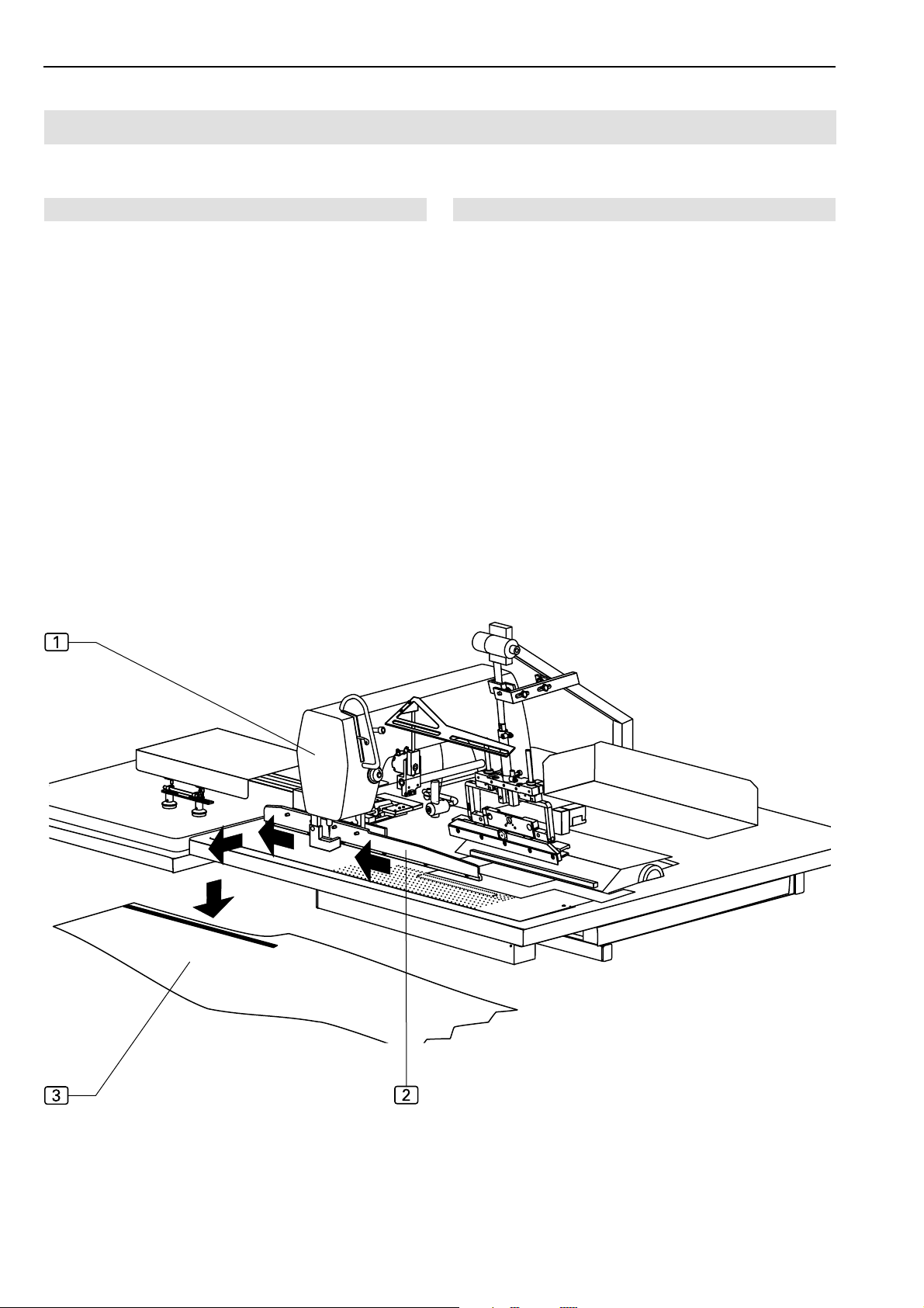
Beisler Automated Sewing Equipment
Functions of the machine
B.2
Short Seam Automat 2112-4 Working Instructions
B.2.10 Sewing the right trousers component
Main clamp, Fig. 14:
The main clamp 2 moves to the insertion station and
picks up the trousers component. The folder moves up
to its start position.
The main clamp transports the trousers component on
the working plate from the insertion station to the sewing head.
Sewing head, Fig. 14:
The sewing head 1 only performs the sewing stitch
and thread cutting functions. All other functions, such
as seam length and determining the beginning or the
end of the seam, are acquired by the machine's sensor system and controlled by the program control in accordance with the set values.
Fig. 14
Threads
Thread stock and thread supply of the sewing head are
monitored by sensors (top thread sensor and rest
thread sensor).
The thread holder can hold two thread spools.
Blowing off, Fig. 14:
After the sewing process, the trousers component
is blown off the worktable with compressed air.
Fig.14
3
- B 22 -
Page 23
Short Seam Automat 2112-4 Working Instructions
Functions of the machine
B.2
Beisler Automated Sewing Equipment
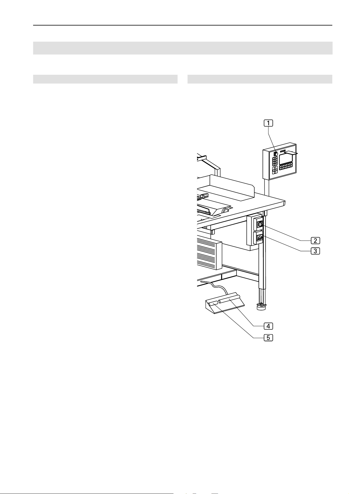
B.2.11 Switches
The short seam automat is equipped with three different
types of switches:
• Emergency switch for stopping a sewing program,
• Supply switch for voltage and vacuum pump,
• control switches for controlling the machine operation.
Emergency switch:
Program stop switch
When the program stop switch 1 is pressed, all machine movements and the sewing process are stopped
immediately.
The switch engages when pressed. Rotating the switch
in the clockwise direction will release the switch, and
it moves back into its original position.
The control program performs a reset.Supply switches
Supply switches:
Main switch
The main switch 2 is used to turn the power supply
of the machine on or off. For safety reasons, the machine must be turned off using the main switch when
it is standing still for an extended period; in this case,
all functional units are deactivated. The main switch
also serves as an additional emergency off switch.
Fig.15
Fig. 15
Vacuum switch
The vacuum switch 3 is used to turn the optional vacuum pump on and off.
Control switches:
Footswitch for machine operation
This footswitch 4 is used to control the individual operating steps of the machine or for starting the fully automatic machine operation.
Footswitch for slash selvage clamp
Depressing the footswitch for the slash selvage clamp
5
will open or close the slash selvage clamp indepen-
dently of the switching state.
- B 23 -
Page 24
Beisler Automated Sewing Equipment
Functions of the machine
B.2
Short Seam Automat 2112-4 Working Instructions
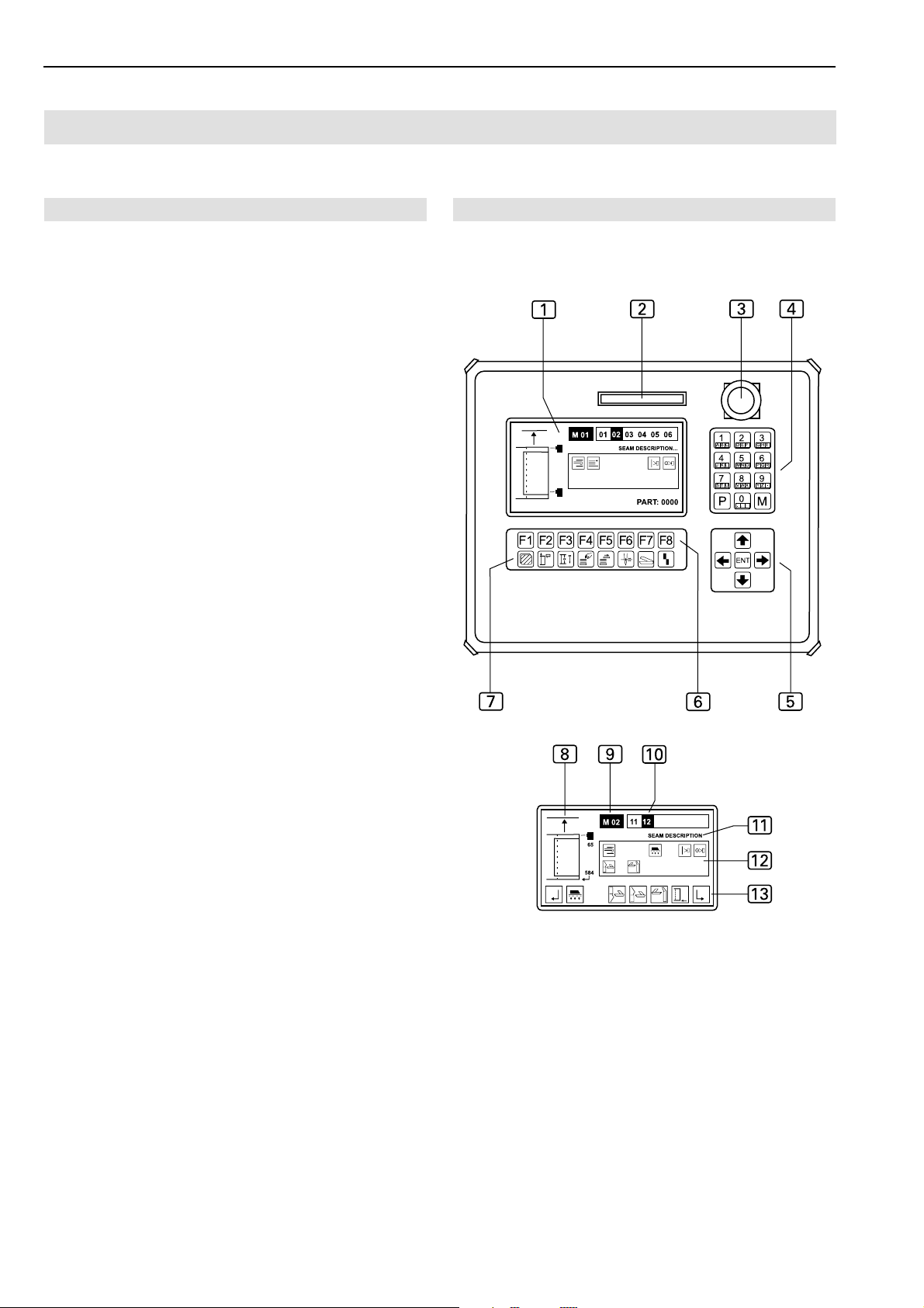
B.2.12 Operating panel
Display
During the operation of the machine, the display
shows the values of the selected sewing program. If
menus were requested, the menu symbol or the corresponding parameters of the function are displayed.
Indicator panel
8
Seam symbol
9
Sewing program description (a sewing program
may consist of several seams)
a
Sewing program seam number
b
Seam description
c
Display field for the enabled seam functions
d
Bar for requestable submenus
Memory card slot
The memory card is the medium for storing the bakkup copies of all program control data. Programs can
be copied to and stored on the memory card and reloaded into the machine control when required.
Program stop switch
If the program stop switch 3 is pressed during the
operation of the machine, all movements and the sewing process are stopped.
2
Fig.16
Fig.16
1
Numeric keypad
The numeric keypad 4 is used to enter all changable
number values.
By pressing the M key, you can request the desired sewing programs.
By pressing the P key, you can request submenus, confirm inputs and exit the programming mode.
Arrow keys
By pressing the UP or DOWN arrow key 5, you can
move the cursor in the selected menu one line up or
down.
By pressing the RIGHT or LEFT arrow key, you can
mark the desired parameter in the selected menu using
the cursor or browse forward or backward if the parameter list consists of several pages.
Function keys
You can use the function keys 6 to request the menus for setting or changing machine functions on the
selected level.
Symbol bar
The symbol bar 7 indicates menus that can be requested using the function keys 6 directly from the start
menu.
All other functions of the machine can be set or changed by selecting the corresponding menus on the different program levels. The corresponding symbols
appear on the display of the operating panel.
- B 24 -
Page 25

Short Seam Automat 2112-4 Working Instructions
Operation
B.3
B.3.1 Safety instructions for operation
Beisler Automated Sewing Equipment
Machine operation:
WARNING - Machine operation intervention!
The machine is driven by electric motors and by compressed air. Any attempt to stop the moving parts of
the machine or to tamper with the movements by hand
may cause severe injuries.
• Keep hands away from machine during machine
operation!
• During the sewing process, keep hands away from
the operating range of the needle!
• If a failure is encountered during machine operation, press the program stop switch immediately!
Clothing:
CAUTION - Unsuited work clothing!
The moving parts of the machine may catch and draw
in loose clothing which may cause severe injuries.
• When operating the machine, do not wear wide or
open clothing!
• Make sure that sleeves are tight-fitting and properly
closed!
Handling the guide laser:
CAUTION - Damage of the retina!
If the eye is directed toward the laser beam for some
time, the retina may be damaged.
• Do not look directly into the laser beam!
• Do not direct laser beam into eyes!
CAUTION - Laser beam change!
An optical change of the laser beam may increase its
luminous intensity and cause eye injuries.
• If the direction of the laser beam is changed, if the
laser beam is misadjusted or if the laser optics are
damaged, turn the machine off and shut it down.
• Do not allow optical equipment (burning glasses
or lenses) to interfere with the laser beam path.
- B 25 -
Page 26
Beisler Automated Sewing Equipment
Operation
B.3
Short Seam Automat 2112-4 Working Instructions
B.3.2 Preparing the machine
Prior to the production start, check the supply connections,
connect the machine to the compressed air and power
supply systems and prepare the sewing head.
1. Insert needle, pass top thread through needle and insert
spool for bottom thread into sewing head (see working
instructions of sewing head manufacturer or supplier).
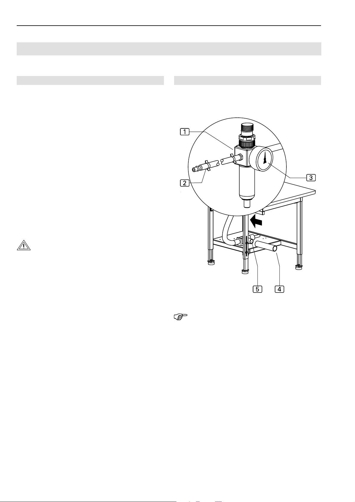
2. Fig.17: Connect machine to compressed air supply by
inserting the plug-in connector 2 of the compressed
air supply hose into the compressed air receptacle in
the operating room. The pressure of the compressed
air is reduced to the required operating pressure of 6
bar by a pressure reducer 1. Check manometer
to see if the correct operating pressure is set. The
pressure reducer is installed at the side mounting wall
of the worktable.
3. Connect machine to power supply system.
WARNING - Electric shock!
3
Fig. 17
Fig. 17
Contact with current-carrying components may cause
a lethal electric shock. Check plug and cable before
connecting machine to power supply system.
• Do not use damaged plugs, sockets or cables to
connect the machine to the power supply system!
• The machine is connected to a power source of 230
V ±10 % at 50/60 Hz.
• Before connecting the machine to the power supply
system, check to see if the ratings of the power
supply system in the operating room correspond
with the ratings on the nameplate at the rear of the
machine.
• If the ratings for voltage (V) and maximum current
(A) do not match, the machine must not be connected.
• Insert the grounding plug into a properly grounded
and fused power socket.
• Make sure that the power supply cable is not subject to tensile or pressure forces.
4. Turn machine on by moving the main switch into the
position I.
5. Turn the vacuum pump of the machine on. Move vauum switch into position I or open on-site vacuum supply.
NOTE - Vacuum supply!
If the machine is equipped with the optional vacuum pump,
the vacuum supply is now ready for operation.
If the machine is prepared for the on-site vacuum supply system, the on-site vacuum hose 4 must be connected
to the sleeve 5 of the vacuum valve.
The machine is ready for operation.
- B 26 -
Page 27
Short Seam Automat 2112-4 Working Instructions
Operation
B.3
Beisler Automated Sewing Equipment
B.3.3 Selecting the sewing program
After the machine has been turned on and the control program has been activated, the sewing program that had
been selected last is set.
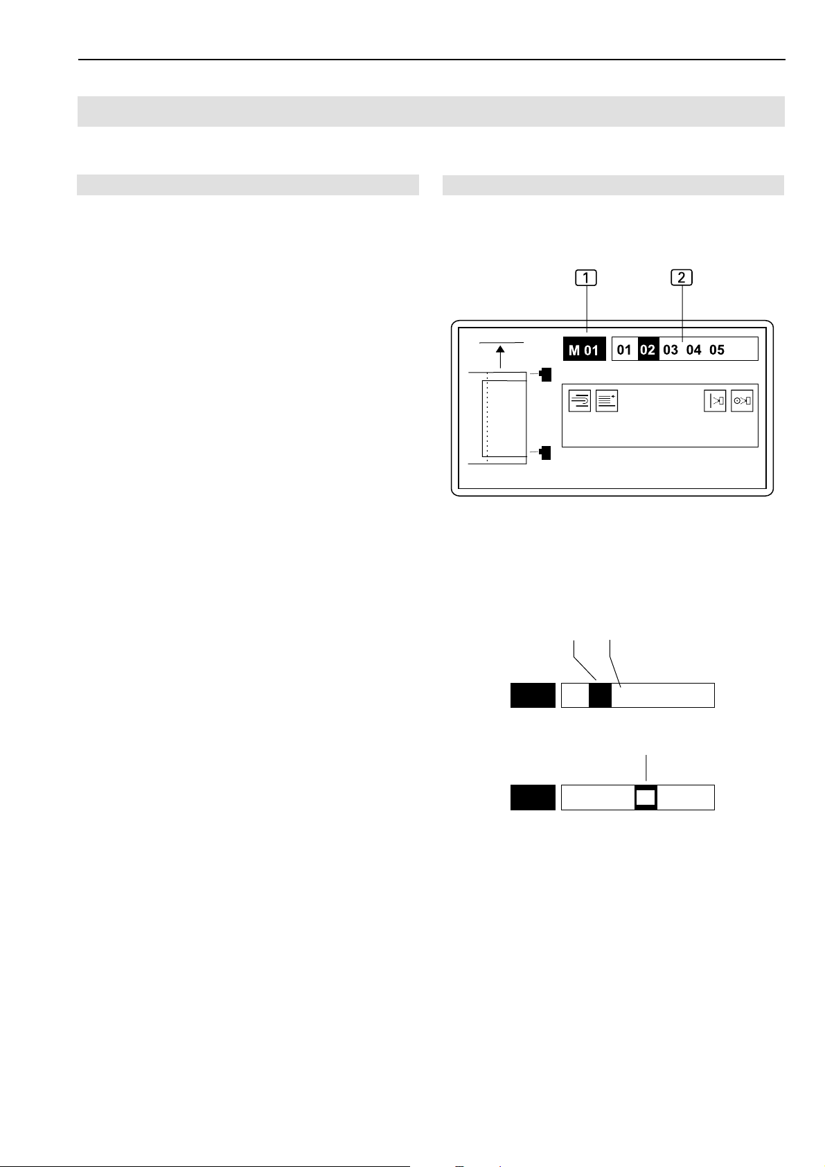
Sewing programs 1 are stored in the memory (M). The
program control memory can store up to 50 sewing programs (M 01-M 50).
Fig. 18: For each sewing program, up to six seam
numbers2 (01, 02, 03, 04, 05) can be assigned.
The program control of the machine is equipped at the
factory with two standard programs:
• Sewing program M 01 with five different seams for crimping over and tucking the pocket edge (see Section
D, Programming Instructions),
• Sewing program M 02 with one seam each for tucking the left slash selvage (12) and the right slash selvage (11) on the trousers component.
In addition, this sewing program is programmed for a
test seam (13) that is restricted to two functions:
• Clamp movement from the insertion station to the
sewing head,
• Starting/ending the complete sewing process.
The test seam is used for checking the clamp transport and the sewing process when the machine is set
up.
Fig. 18
Fig. 19
1
Fig. 18/19
2
1. Select sewing program at operating panel.
Request memory::
• Press key.
Select sewing program number, e.g. 01:
• Press and keys.
The selected program is activated immediately.
2. Select seam number of desired seam.
Move cursor to seam number:
• Press 0 or / key.
Confirm selection:
• Press % key.
M01
01 02 03 04 05
3
M01
Fig. 19: Display during seam number selection:
1
2
3
Active seam number
Passive seam number
Seam number is selected
01 02 03 04 05
- B 27 -
Page 28

Beisler Automated Sewing Equipment
Operation
B.3
Short Seam Automat 2112-4 Working Instructions
B.3.4 Activating additional seam numbers
1. Select seam number of desired seam.
Move cursor to seam number:
• Press 0 or / key.
Confirm selection:
• Press % key.
The seam number of the activated seam appears blackened.
B.3.5 Deactivating a seam number
1. Select seam number of desired seam.
Move cursor to seam number:
• Press 0 or / key.
B.3.6 Setting the thread clamp manually
Before the first start of a sewing program, the top thread
clamp must be activated to protect the top thread from
being pulled out of the needle when the machine starts.
• Press key.
B.3.7 Operating the stacker
To ensure easy access to the sewing pieces on the stacker,
the lift table can be lowered, and the sliding table can be
moved backward.
1. Lower or raise the lift table.
• Press key.
2. Move sliding table forward or backward.
Confirm selection:
• Press % key.
The seam number of the deactivated seam is no longer
blackened.
• Press key.
- B 28 -
Page 29

Short Seam Automat 2112-4 Working Instructions
Operation
B.3
Beisler Automated Sewing Equipment
B.3.8 Testing the cutters
Sharpness and function of the three cutters can be chekked individually. When the corresponding function key is
depressed, a cutting movement is performed.
1. Request the cutter test menu.
• Press key.
M
The display shows the symbols of the selectable functions
on this level.
&GHIQ
2. Rear working plate cutter (left trouser component).
G
• Press key.
3. Front working plate cutter (right trouser component).
H
• Press key.
B.3.9 Resetting the day counter to zero
Use this function to reset the day counter for a program
cycle or for a completed working cycle to zero.
1. Move to level 1.
Press key.
The display shows the symbols for selectable functions
on this level.
&'(6)@7
2. Request the day counter reset function.
)
• Press key.
The day counter is now reset to zero.
3. Return to start level.
Press key.
Display: PART: 0000
4. Pick-up plate cutter (left slash selvage).
I
• Taste drücken
5. Load bobbin.
Q
• Press key.
- B 29 -
Page 30

Beisler Automated Sewing Equipment
Operation
B.3
Short Seam Automat 2112-4 Working Instructions
B.3.10 Quick stitch width setting
The quick stitch width adjustment makes the selection of
4 preadjusted different stitch widths possible.
• Fig. 20 Use the handwheel 1 to adjust the stitch width
to the required range.
• pocket edge
• pocket bag
2
3
Fig. 20
Fig. 20
1
1
2
3
4
2
3
- B 30 -
Page 31
Short Seam Automat 2112-4 Working Instructions
Operation
B.3
Beisler Automated Sewing Equipment
B.3.11 Controlling machine cycle
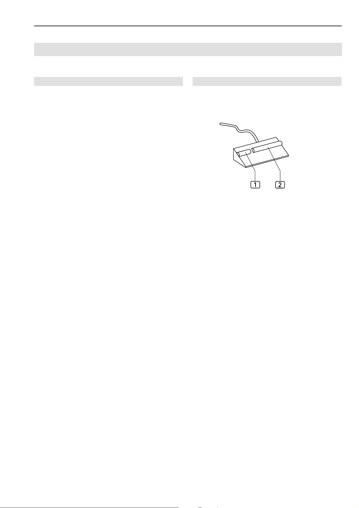
The complete process of the sewing programs is controlled
by using the two footswitches, Fig. 21:
• Footswitch for slash selvage clamp
• Footswitch for machine operation
Each sewing program offers several alternatives (modes)
for controlling the process.
The sewing program M 01:
"Crimping over and sewing pocket edge" which contains
five different seams is controlled exclusively by using the
footswitch for machine operation 2.
The sewing program M 02 with seam 12:
"Crimping over left slash selvage and sew onto left trouser component" is controlled by using both footswitches.
• The footswitch for the slash selvage clamp 1 closes
the slash selvage clamp after the slash selvage has
been inserted,
• The footswitch for machine operation 2 controls the
entire subsequent process of the sewing programm.
The sewing program M 02 with seam 11:
"Sewing right slash selvage to right trousers component"
is controlled exclusively by using the footswitch for machine operation 2.
1
2
Fig 21
Fig. 21
The sewing program M 02 with seam 13:
"Test seam" is also controlled by using the footswitch for
machine operation 2.
- B 31 -
Page 32

Beisler Automated Sewing Equipment
Operation
B.3
B.3.12 Pocket edge start mode
Short Seam Automat 2112-4 Working Instructions
The machine cycle "Crimping over and sewing pocket
edge" can be performed in four different modes (Mode 00,
Mode 01, Mode 02, Mode 03). The factory setting is Mode
01 which starts a largely fully-automatic machine cycle.
However, this requires that the sewing program M 01 and
one of the seams 01 - 05 has been set.
Controlling machine cycle in mode 00:
1. Line up pocket edge.
2. Depress footswitch for machine cycle and keep depressed:
• The folder picks up the pocket edge.
3. Release footswitch:
• Further machine cycle is fully automatic:
The pocket bag clamp closes.
The folder puts the pocket edge onto the pocket
bag.
The main clamp picks up the sewing pieces and
transports them to the sewing head.
The sewing pieces are tucked, then the transport
stamp transports them to the stacker and puts them
down.
The main clamp returns to its original position. The
next machine cycle starts.
NOTE - Supplying sewing pieces!
If the fully automatic machine cycle was started, the next
sewing pieces can be lined up.
The footswitch for machine cycle remains deactivated until
the main clamp reaches its start position; after that, the
next machine cycle can be started.
Controlling machine cycle in mode 01:
1. Line up pocket edge.
2. Depress, then release footswitch for machine cycle:
• The folder picks up the pocket edge.
3. Depress, then release footswitch for machine cycle:
• The pocket bag clamp closes.
4. Depress, then release footswitch for machine cycle:
• The folder moves to the left and puts the pocket
edge down.
5. Depress, then release footswitch for machine cycle:
• The main clamp picks up the sewing pieces and
moves to the sewing head.
6. Depress, then release footswitch for machine cycle:
• The sewing pieces are tucked.
7. Depress, then release footswitch for machine cycle:
• The transport stamp transports the sewing pieces
to the stacker and puts them down. The main clamp
returns to its start position. The next machine cycle starts.
Alternatively, mode 01 can be controlled as follows :
After any working step, the further machine cycle can be
continued automatically:
1. Depress footswitch for machine cycle and keep depressed:
• The machine cycle is continued automatically.
NOTE - Supplying sewing pieces!
When the sewing pieces are at the sewing head, the next
pocket edge can be lined up.
The footswitch for machine cycle remains deactivated until
the main clamp reaches its original position; after that, the
next machine cycle can be started.
Controlling machine cycle in mode 02:
1. Line up pocket edge.
2. Depress footswitch for machine cycle and keep depressed:
• The folder picks up the pocket edge.
3. Release footswitch for machine cycle:
• The pocket bag clamp closes.
• The folder moves to the left and puts the pocket
edge down.
• The main clamp picks up the sewing pieces.
4. Depress, then release footswitch for machine cycle:
•Further machine cycle is fully automatic.
NOTE - Supplying sewing pieces!
When the sewing pieces are at the sewing head, the next
pocket edge can be lined up.
The footswitch for machine cycle remains deactivated until
the main clamp reaches its start position; after that, the
next machine cycle can be started.
- B 32 -
Page 33

Short Seam Automat 2112-4 Working Instructions
Operation
B.3
Beisler Automated Sewing Equipment
Controlling machine cycle in mode 03:
1. Line up pocket edge.
2. Depress footswitch for machine cycle and keep depressed:
• The folder picks up the pocket edge.
3. Release footswitch for machine cycle:
• The pocket bag clamp closes.
4. Depress, then release footswitch for machine cycle:
• The folder moves to the left and puts the pocket
edge down.
5. Depress, then release footswitch for machine cycle:
• Further machine cycle is fully automatic:
NOTE - Supplying sewing pieces!
When the sewing pieces are at the sewing head, the next
pocket edge can be lined up.
The footswitch for machine cycle remains deactivated until
the main clamp reaches its original position; after that, the
next machine cycle can be started.
- B 33 -
Page 34

Beisler Automated Sewing Equipment
Operation
B.3
B.3.13 Start mode "Left slash selvage"
Short Seam Automat 2112-4 Working Instructions
The machine cycle "Crimping over left slash selvage and
sewing to left trousers component" can be performed in
two different modes (Mode 04, Mode 05). The factory
setting is Mode 04 which starts a largely fully-automatic
machine cycle. However, this requires that the sewing
program M 02 with seam 12 has been set.
Controlling machine cycle in Mode 04:
1. Line up left slash selvage.
2. Depress left footswitch for slash selvage clamp:
• The slash selvage clamp closes.
3. Depress footswitch for machine operation:
• The folder moves right to the pick-up plate.
• The cutter "slash selvage" cuts.
• The slash selvage is crimped over and picked up.
4. Depress footswitch for machine operation and keep
depressed:
• The rear cutter "left trousers component" opens,
vacuum is activated.
• Line up and smooth out left trousers component.
5. Release footswitch:
• The rear cutter "left trousers component" cuts.
• The folder puts the slash selvage down onto the
left trousers component.
• The main clamp picks up the sewing pieces.
6. Depress footswitch for machine operation:
• Further machine cycle is fully automatic:
The main clamp transports the sewing pieces to
the sewing head.
The sewing pieces are tucked and blown off from
the working plate with compressed air.
The main clamp returns to its start position.
The next machine cycle starts.
NOTE - Supplying sewing pieces!
If the fully automatic machine cycle was started, the next
sewing pieces can be lined up.
The footswitch for machine operation remains deactivated until the main clamp reaches its start position; after that,
the next machine cycle can be started.
Controlling machine cycle in Mode 05:
1. Line up left slash selvage.
2. Depress left footswitch for slash selvage clamp:
• The slash selvage clamp closes.
3. Depress footswitch for machine operation:
• The folder moves right to the pick-up plate.
• The cutter "slash selvage" cuts.
• The slash selvage is crimped over and picked up.
4. Depress footswitch for machine operation and keep
depressed:
• The rear cutter "left trousers component" opens,
vacuum is activated.
• Line up and smooth out left trousers component.
5. Release footswitch:
• The rear cutter "left trousers component" cuts.
• The folder puts the slash selvage down onto the
left trousers component.
6. Depress footswitch for machine operation:
• The main clamp moves to the insertion station and
picks up the sewing pieces.
7. Depress footswitch for machine operation:
• Further machine cycle is fully automatic:
The main clamp transports the sewing pieces to
the sewing head.
The sewing pieces are tucked and blown off from
the working plate with compressed air.
The main clamp returns to its start position.
The next machine cycle starts.
NOTE - Supplying sewing pieces!
If the fully automatic machine cycle was started, the next
sewing pieces can be lined up.
The footswitch for machine operation remains deactivated until the main clamp reaches its start position; after that,
the next machine cycle can be started.
- B 34 -
Page 35

Short Seam Automat 2112-4 Working Instructions
Operation
B.3
B.3.14 Start mode "Right slash selvage"
Beisler Automated Sewing Equipment
The machine cycle "Sew right slash selvage to right trousers component" can be performed in two different modes (Mode 06, Mode 07). The factory setting is Mode 07
which starts a largely fully-automatic machine cycle. However, this requires that the sewing program M 02 with seam
11 has been ses.
Controlling machine cycle in Mode 06:
1. Depress footswitch for machine operation:
• The folder moves right to the pick-up plate.
• The front cutter "right trousers component" opens,
2. Depress footswitch for machine operation and keep
depressed:
• Vacuum is activated.
• Line up and smooth out right trousers component.
3. Release footswitch:
• The front cutter "right trousers component" cuts,
the slash selvage stop swivels to the trousers component.
• Line up right slash selvage to right trousers component at stop.
4. Depress footswitch for machine operation:
• Further machine cycle is fully automatic:
The folder moves left.
The main clamp transports the sewing pieces to
the sewing head.
The sewing pieces are tucked and blown off from
the working plate with compressed air.
The main clamp returns to its start position.
The next machine cycle starts.
NOTE - Supplying sewing pieces!
If the fully automatic machine cycle was started, the next
sewing pieces can be lined up.
The footswitch for machine operation remains deactivated until the main clamp reaches its start position; after that,
the next machine cycle can be started.
Controlling machine cycle in Mode 07:
1. Depress footswitch for machine operation:
• The folder moves right to the pick-up plate.
• The front cutter "right trousers component" opens,
2. Depress footswitch for machine operation and keep
depressed:
• Vacuum is activated.
• Line up and smooth out right trousers component.
3. Release footswitch:
• The front cutter "right trousers component" cuts,
the slash selvage stop swivels to the trousers component.
• Line up right slash selvage to right trousers component at stop.
4. Depress footswitch for machine operation:
• The folder moves left.
• The main clamp moves to the insertion station and
picks up the sewing pieces.
5. Depress footswitch for machine operation:
• Further machine cycle is fully automatic:
The main clamp transports the sewing pieces to
the sewing head.
The sewing pieces are tucked and blown off from
the working plate with compressed air.
The main clamp returns to its start position.
The next machine cycle starts.
NOTE - Supplying sewing pieces!
If the fully automatic machine cycle was started, the next
sewing pieces can be lined up.
The footswitch for machine operation remains deactivated until the main clamp reaches its start position; after that,
the next machine cycle can be started.
- B 35 -
Page 36

Beisler Automated Sewing Equipment
Operation
B.3
Short Seam Automat 2112-4 Working Instructions
B.3.15 Resetting line-up process
This function depends on the selected machine cycle
mode. It only refers to machine movements that can be
executed before the start of the automatic process.
The machine movements will be reset to start position
immediately.
• Press key (several times if required).
"
B.3.16 Moving machine to zero position
Prior to starting the production, after machine tests or after
corrections to sewing programs, the machine must be returned to zero position for starting the machine cycle:
1. Press program stop switch.
2. Unlock program stop switch.
(See Section B.3.13, Stopping a sewing program)
B.3.17 Stopping a sewing program
B.3.18 Turning the machine off
For extended work intermissions, the machine must be
turned off completely.
1. Turn power supply off by moving main switch to 0 position.
B.3.19 Periodic cleaning of the machine
The machine must be cleaned after large production series
or at least once a day, whichever occurs first.
CAUTION - Danger of injuries!
If the machine is put in motion accidentally, persons
in its direct vicinity may be caught by moving parts
which may cause injuries.
Prior to any cleaning work, disconnect the machine
from the power supply!
• Turn the machine off using the main switch.
• Remove the power plug from the socket and protect it from accidental reconnection.
1. Press program stop switch.
When this switch is pressed, all machine movements
and the sewing process are stopped immediately. The
switch engages when pressed.
To restart the machine after a program stop, all functions
must be reset, and the machine must be returned to zero
position by unlocking the program stop switch.
2. Unlock program stop switch.
Slightly rotate switch in the clockwise direction. The
switch returns to its original position.
The control program performs a reset.
Periodic cleaning:
1. Remove fabric residues.
2. Using compressed air, blow off dust and thread residues at the sewing head, at the working plate, at the
main clamp and at the linear rail.
- B 36 -
Page 37

Short Seam Automat 2112-4 Working Instructions
Beisler Automated Sewing Equipment
Section C
Service Instructions
- C 37 -
Page 38

Short Seam Automat 2112-4 Working InstructionsBeisler Automated Sewing Equipment
Service Instructions
Section C
Contents
C.1 Delivery of the machine .................................................................................................... 39
C.1.1 Packaging.................................................................................................................... 39
C.1.2 Scope of delivery......................................................................................................... 39
C.2 Storage and location requirements ................................................................................. 40
C.2.1 Floor quality ................................................................................................................. 40
C.2.2 Interior climate ............................................................................................................. 40
C.2.3 Floor space required ................................................................................................... 40
C.2.4 Supply connections ..................................................................................................... 40
C.3 Start-up ............................................................................................................................... 41
C.3.1 Machine table alignment .............................................................................................41
C.3.2 Compressed air connections ...................................................................................... 42
C.3.3 Connecting the machine to the power supply ............................................................ 43
C.3.4 Safety check ................................................................................................................ 43
C.4 Operation and shut-down................................................................................................. 44
C.4.1 Working with the machine ........................................................................................... 44
C.4.2 Machine shut-down ..................................................................................................... 44
C.5 Maintenance....................................................................................................................... 45
C.5.1 Inspection ....................................................................................................................45
C.5.2 Cleaning ...................................................................................................................... 45
C.5.3 Service ........................................................................................................................ 46
C.5.4 Repairs ........................................................................................................................ 47
Operating panel replacement ................................................................................. 47
Clamp transport belt replacement .......................................................................... 48
Checking clamp travel steps ................................................................................... 49
Setting clamp travel steps ....................................................................................... 49
Clamp rail replacement ........................................................................................... 50
Cutter replacement ................................................................................................. 50
C.5.5 Machine set-up ............................................................................................................ 51
Guide laser adjustment ........................................................................................... 51
Adjusting clamp rail to machine function ................................................................52
Clamp rail clamping pressure adjustment .............................................................. 52
Adjustment of clamp slide disengagement position ...............................................53
Adjustment of the clamp rail parallel orientation .................................................... 54
Folder to clamp rail alignment ................................................................................ 55
Folder lower position adjustment ............................................................................ 56
Folder to pick-up plate alignment ........................................................................... 57
Folder bar to folder clamp alignment ...................................................................... 58
Right slash selvage stop alignment ........................................................................ 59
Photocell light sensitivity setting .............................................................................61
Installation stepper motor ....................................................................................... 62
Setting the thread cutter ......................................................................................... 63
Checking the rest thread monitor ........................................................................... 64
Adjusting the photocell ............................................................................................ 64
C.6 Troubleshooting ................................................................................................................ 66
C.7 Specifications .................................................................................................................... 68
- C 38 -
Page 39

Short Seam Automat 2112-4 Working Instructions
Delivery of the machine
C.1
Beisler Automated Sewing Equipment
C.1.1 Packaging
The machine is delivered in a solid packaging box on a
pallet. All packaging materials can be separated and reused.
• Pallet made of pine wood
• Packaging box made of plywood / transport carton
• Polyethylene film (PE)
NOTE - Shipping braces!
During shipping, moving machine parts are protected with
shipping braces (cable ties). The positions of all parts fitted
with shipping braces are marked with red labels.
After the machine has been installed and aligned, the
shipping braces must be removed.
NOTE - Damages in transit!
If any damage presumably caused by incorrect transport
is found when the machine is unpacked, please contact
your supplier immediately.
C.1.2 Scope of delivery
The machine is delivered in an operative condition. The
scope of delivery comprises:
Short seam automat with sewing head:
• The machine is equipped with several customerspecific accessories. For checking the exact layout, the information on the delivery note is authoritative.
• Service kit with machine oil.
Operating panel and program control:
• Preinstalled (ready-for-use) operating panel.
• Memory card with factory-programmed standard
sewing program.
Technical documents:
• Operating instructions.
• Service instructions.
• Programming instructions.
- C 39 -
Page 40

C.2
Short Seam Automat 2112-4 Working InstructionsBeisler Automated Sewing Equipment
Storage and location requirements
C.2.1 Floor quality
The floor of the room where the machine is to be installed must have a sufficient surface strength. The location
of the machine must be free of vibrations.
If several machines are to be installed in one room, the
static load bearing capacity of the ceiling must be considered.
Weight:
• Machine with accessories approx 210 kg
C.2.2 Interior climate
Climatic requirements for the operating room:
The machine must only be stored or operated in closed
operating rooms.
• Room temperature +10 °C to +45 °C
• Relative humidity 80 % max.
C.2.3 Floor space required
C.2.4 Supply connections
The machine requires on-site power and compressed air
sources.
Power connection:
The power supply of the machine requires a properly
grounded power connection with:
• Grounding plug 230 V ± 10 %, 50/60 Hz
• Fusing 16 A
NOTE - Peak voltages!
The correct function of the machine requires that the power
system supplies a constant current. Peak voltages may
particularly impair the stability of the program control.
Compressed air supply:
The on-site compressed air supply system must meet the
following requirements:
• Operating pressure 6 bar
• Compressed air quality oil-free
• Compressed air consumption 4.16 NL
For operation during production and for service works, the
machine must be freely accessible from all sides. On all
sides, there must be a minimum clearance of 1 m.
Machine dimensions:
• L x W x H 1700 x 1400 x 1700 mm
NOTE - Electromagnetic interference!
The machine must not be installed in the immediate vicinity
of devices or electrical components (e.g. transformers)
generating a strong magnetic field as otherwise the correct function of the program control may be impaired.
Vacuum source:
The on-site vacuum source must meet the following requirements:
• Displacement (minimum) 130 m³/h
- C 40 -
Page 41
Short Seam Automat 2112-4 Working Instructions
Start-up
C.3
Beisler Automated Sewing Equipment
C.3.1 Machine table alignment
After the machine has been installed at the desired location, the machine table must be aligned:
• Set machine table to required height.
• Align machine table horizontally on all sides.
Setting table height:
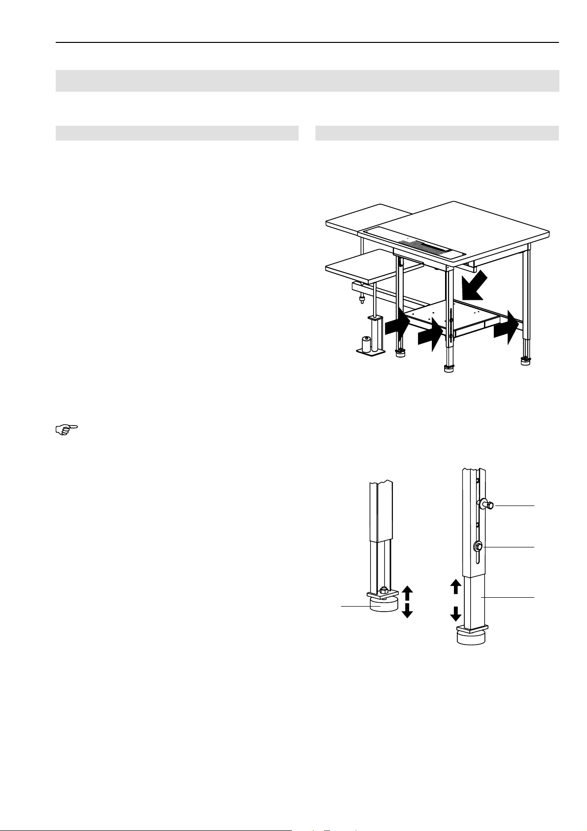
1. Fig. 1: Lift machine: Connect lifting device at lift points
(arrows) below the crossmembers. If the machine is
equipped with optional transport rollers, release brakes before lifting.
2. Fig. 2: Loosen lockscrews 2 on all guide rails.
3. Pull table legs 3 out to the desired length and retighten lockscrews 2.
4. Lower machine to floor.
Horizontal positioning of the machine table:
1. Place bubble level onto working plate.
2. Fig. 2: Loosen table leg lock nuts 1.
3. Align machine table horizontally on all sides by raising
or lowering table legs as required.
4. Retighten table leg lock nuts.
Fig. 1/2
Fig. 1
NOTE - Shipping braces!
Before the machine is connected to the power supply system, all shipping braces must be removed.
• Cut off cable ties.
• Remove labels.
Fig. 2
2
2
3
1
- C 41 -
Page 42
C.3
Short Seam Automat 2112-4 Working InstructionsBeisler Automated Sewing Equipment
Start-up
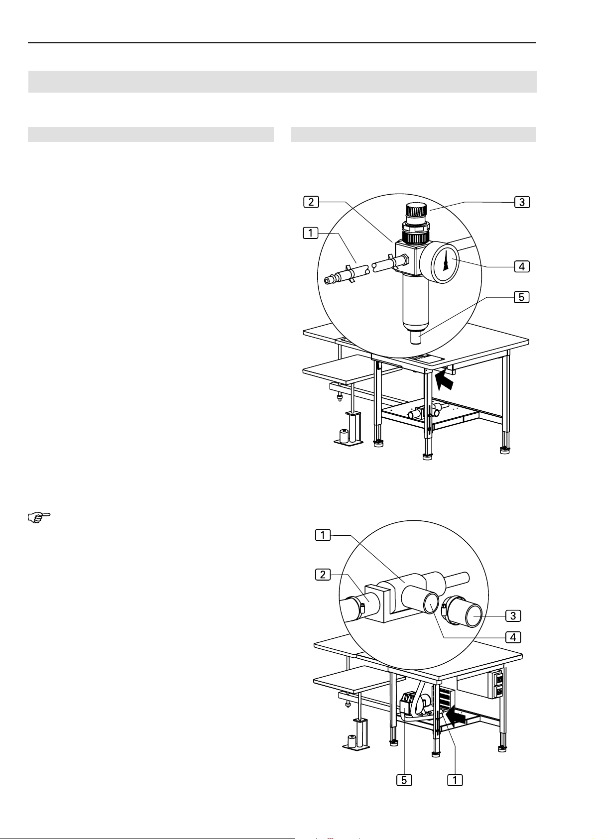
C.3.2 Compressed air connections
The compressed air connection is preinstalled on the
machine. It comprises the following components:
• Pressure reducer 2 with manometer 4 and water
separator 5,
• Pressure hose with push-in plug 1.
The pressure reducer is installed at the side mounting wall
of the worktable.
Connecting the machine to the compressed air supply system:
1. Connect pressure hose plug to on-site terminal unit.
2. Open on-site compressed air supply.
3. Set pressure reducer to a machine operating pressure
of 6 bar by rotating pressure reducer knob 3 and read
value on manometer 4:
• To increase pressure, rotate in clockwise direction.
• To reduce pressure, rotate in counter-clockwise direction.
Connecting the machine to the vacuum supply system:
If the machine is equipped with the optional vacuum
pump4, no further installation is required. The vacuum
system is ready for operation.
If the machine is delivered without vacuum pump, the onsite vacuum source must be connected to the machine's
vacuum valve. The vacuum valve 1 is mounted below
the worktable.
Fig. 3/4
Fig. 3
Fig. 4
NOTE - Required components!
The following components are required on the site:
• A vacuum hose 3 with an inner diameter of at least
1¼ '' or, as required, an adapter or reducing fitting to
accommodate the on-site vacuum hose on the sleeve (outer diameter 1¼ '') of the machine's vacuum
valve.
• A hose clamp with an inner diameter of at least 1¼ ''.
1. Connect the on-site vacuum hose to the sleeve 4 of
the vacuum valve 1.
2. Attach vacuum hose using the hose clamp.
3. The sleeve 2 connects the aspirator system of the
working plate to the vacuum valve.
4. Open on-site vacuum source.
- C 42 -
Page 43

Short Seam Automat 2112-4 Working Instructions
Start-up
C.3
Beisler Automated Sewing Equipment
C.3.3 Connecting the machine to the power supply
The power cable and the power plug are preinstalled on
the machine. The footswitches for controlling the machine
operation and the bundle clamps are installed as well.
Connecting the machine to the power supply system:
1. Put footswitches for machine operation and for bundle
clamp onto desired locations on floor at front side of
machine.
2. Insert power plug into socket.
WARNING - Electric shock!
Contact with current-carrying components may cause
a lethal electric shock. Check plug and cable before
connecting machine to power supply system.
• Do not use damaged plugs, sockets or cables to
connect the machine to the power supply system!
• The machine is connected to a power source of 230
V ±10 % at 50/60 Hz.
• Before connecting the machine to the power supply
system, check to see if the ratings of the power supply system in the operating room correspond with the
ratings on the nameplate at the rear of the machine.
• If the ratings for voltage (V) and maximum current (A)
do not match, the machine must not be connected.
• Insert the grounding plug into a properly grounded and
fused power socket.
• Make sure that the power supply cable is not subject
to tensile or pressure forces.
• Route the power supply cable in a way that ensures
free access to and around the machine.
C.3.4 Safety check
Before the machine is released for operation, all safety devices must be checked for their correct operation.
CAUTION - Danger of injuries!
The safety devices protect the operating and service
personnel while working on or with the machine.
If the safety devices are fully or partially inoperative,
the machine must not be started up.
Perform safety check:
1. Check to see if the cover above the clamp transport
unit is correctly and safely installed.
2. Check to see if the finger protection at the sewing head
covers the needle effectively.
3. Make sure that the guide laser is not directed into the
view area of the machine operator.
4. The main switch also serves as an emergency off
switch. To check the function of this switch, turn the machine on, start a machine cycle and turn the machine
off during the tucking process using the main switch.
All operational movements of the clamp and of the sewing head must stop, and the program control must
switch off.
5. Check the function of the program stop switch. Start
a machine cycle and press the switch. All operational
movements of the clamp and of the sewing head must
stop.
6. Unlock the program stop switch. The program control
starts a reset, and the clamp must return to its start
position.
NOTE - Works to the electrical system!
Works to the electrical system of the machine must only
be carried out by qualified and authorized expert personnel.
Tampering with the machine without authorization makes
the warranty void.
- C 43 -
The machine is ready for operation.
Page 44

C.4
Short Seam Automat 2112-4 Working InstructionsBeisler Automated Sewing Equipment
Operation and shut-down
C.4.1 Working with the machine
Factory settings:
The program control of the machine is equipped at the
factory with two standard programs:
• Sewing program M 01 with five different seams for
"crimping over and sewing pocket edge" (see part D,
programming instructions).
• Sewing program M 02 with one seam each for tucking the left slash selvage (12) and the right slash selvage (11) on the trousers component.
C.4.2 Machine shut-down
When the machine is to be shut down, it must be disconnected from all supply sources.
Disconnecting the machine from the power supply
system:
1. Turn machine off using main switch. Move switch to
position "0".
2. Remove power plug from socket and protect it against
accidental reconnection.
Disconnecting the machine from the compressed air
supply system:
1. Shut off on-site compressed air.
2. Remove compressed air hose plug from terminal unit.
NOTE - Dust-proof protection!
If the machine is to be shut down for an extended period
of time, it should be covered with a plastic tarpaulin.
- C 44 -
Page 45

Short Seam Automat 2112-4 Working Instructions
Maintenance
C.5
Beisler Automated Sewing Equipment
WARNING - Electric shock:
Contact with current-carrying components may cause
a lethal electric shock.
If the machine is put in motion accidentally, persons
in its direct vicinity may be caught by moving parts
which may cause injuries.
Prior to any service, cleaning or maintenance works,
disconnect the machine from the power supply system!
• Turn the machine off using the main switch.
• Remove power plug from socket and protect it
against accidental reconnection.
• If the power supply is not required for repair or setup work, the machine must be disconnected from
the power supply system.
C.5.1 Inspection
The machine must be inspected annually.
The inspection comprises particularly the following items:
• safety devices of the machine,
• operativeness of the program control,
• correct function of inputs and outputs.
C.5.2 Cleaning
The machine must be cleaned after large production series, or at least once a day, whichever occurs first.
Cleaning the machine surfaces:
1. Disconnect machine from power supply system.
2. Remove fabric residues.
3. Using compressed air, blow off dust and thread residues at the sewing head, at the working plate, at the
clamp and at the linear rail.
4. Wipe machine parts dry using a dry, clean cloth.
NOTE - Plastic surfaces!
Some parts of the machine surfaces are made of plastic
materials. Solvents may dissolve plastics and make them
unusable.
Do not clean the machine surfaces (particularly the operating panel) with cleaning agents that contain solvent.
- C 45 -
Page 46
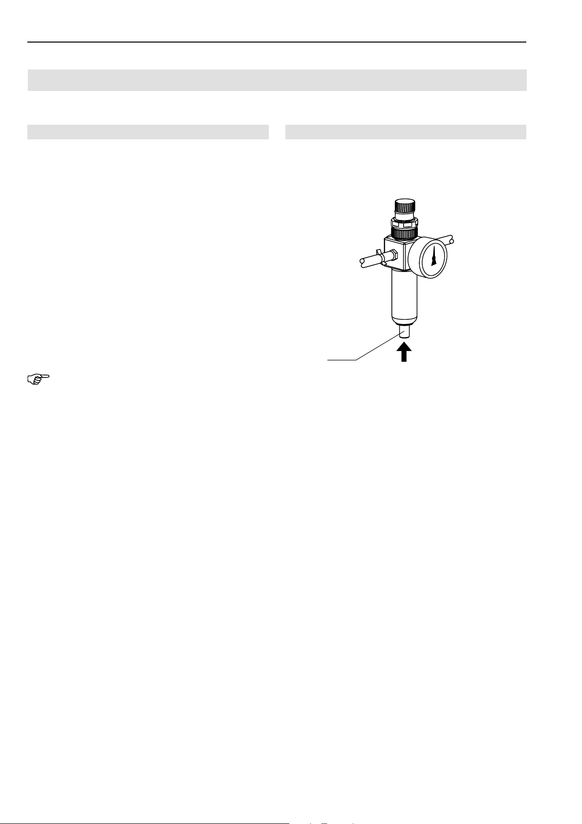
C.5
Short Seam Automat 2112-4 Working InstructionsBeisler Automated Sewing Equipment
Maintenance
C.5.3 Service
The following service works must be carried out in weekly
intervals.
Oiling the clamp rail:
1. Disconnect machine from power supply.
2. Wipe clamp rails clean using a soft, oil-saturated cloth.
The scope of delivery comprises 0.25 l of oil. When this
oil is used up, you can order the special machine oil
for service from the manufacturer or supplier of the machine.
Emptying the water separator:
1. Disconnect machine from power supply.
2. Fig. 5: Drain water at pressure reducer water separator
into suited container. Press button 1 at pressure reducer collector and keep pressed until all the water has
been drained.
NOTE - Sewing head!
For information about service of the sewing head, please refer to the working instructions of the sewing head.
Fig. 5
Fig. 5
1
- C 46 -
Page 47
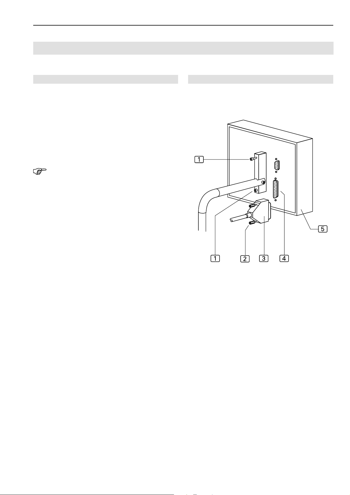
Short Seam Automat 2112-4 Working Instructions
Maintenance
C.5
Beisler Automated Sewing Equipment
C.5.4 Repairs
Any repairs to the machine must only be carried out by:
• authorized Technical Service,
• personnel that has been instructed about the setting
up and maintenance of the machine on the occasion
of a training by the supplier or manufacturer.
Use only original spare parts for installing or replacing
machine components.
Manufacturer and supplier will not be held responsible for
spare parts from third parties.
NOTE - Programming instructions!
Repairs require that machine components carry out their
individual movements and that the machine movements
are tested. These functions are controlled on level 1 of the
service menu.
For the necessary instructions, please refer to the programming instructions.
Operating panel replacement:
1. Disconnect machine from power supply.
2. Remove two lock screws 2 and disconnect interface
connector3.
3. Remove retaining screws 1 from operating panel
bracket.
4. Remove operating panel 5, install new panel and
secure using screws.
5. Connect interface connector to receptacle 4 and secure using two lock screws 2 .
Fig. 6
Fig. 6
- C 47 -
Page 48
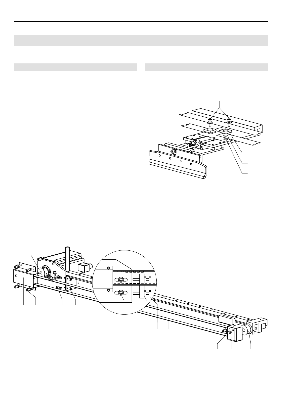
C.5
Short Seam Automat 2112-4 Working InstructionsBeisler Automated Sewing Equipment
Maintenance
C.5.4 Repairs
Clamp transport belt replacement:
1. Disconnect machine from power supply system.
2. Slide clamp to left until it reaches stop position.
3. Fig. 8: Remove retaining screws 3 from drive roller
cover2and remove cover.
4. Remove two retaining screws from slide roller cover
8
and remove cover 9.
5. Loosen two belt lock screws 4 and release belt tension7.
6. Loosen lock nuts 6 of set screws 5 and rotate two
set screws backward.
7. Fig. 7: Remove two connecting screws 1 from main
clamp pedestal. Remove belt.
8. Fig. 8: Install new belt to drive roller 1 and to guide
rollera.
9. Fig. 7: The ends of the belt 3 are fitted with holes.
Position the two ends of the belt with the belt clamp
exactly over the holes on the pedestal 4 and secure them using screws.
2
Fig. 7/8
Fig. 7
1
2
3
4
10.Fig. 8: Tension belt by tightening two set screws 5
until the belt can be depressed approx 10 mm with
distinct counterpressure at the middle of the transport rail.
Tighten lock nuts 6 and lock screws 4.
11.Install the two covers 2 and 9.
Fig. 8
1
2
3
4
5
4
6
5
7
8
9
a
- C 48 -
Page 49

Short Seam Automat 2112-4 Working Instructions
Maintenance
C.5
C.5.4 Repairs
Beisler Automated Sewing Equipment
Checking clamp travel steps:
After the toothed belt has been replaced, the number of
clamp travel steps must be checked.
At the factory, this value has been set:
• to 00 steps at the right stop,
• to 735 steps at the left stop.
These values must be adhered to.
1. Switch machine on and allow to reference.
2. Go to diagnostics menu:
• Press key
• Press key
3. Go to clamp transport menu:
• Press key
4. Go to clamp motor travel steps:
• Press key
5. Confirm safety prompt:
Setting clamp travel steps:
If the result of the clamp travel step check is not 735 mm
for the left stop, switch S04 must be repositioned:
• If the value is higher than 735 mm, the switch must
be repositioned to the left.
• If the value is lower than 735 mm, the switch must be
repositioned to the right.
1. Loosen two switch retaining screws.
2. Move switch in required direction and tighten screws.
3. Recheck number of clamp travel steps. If required, the
setting process must be repeated until the correct value
of 735 mm is displayed.
• Press % key
6. Push clamp rail manually to the right stop. The display
must show 00 mm.
7. Push clamp rail manually to the left stop. The display
must show 735 mm.
- C 49 -
Page 50
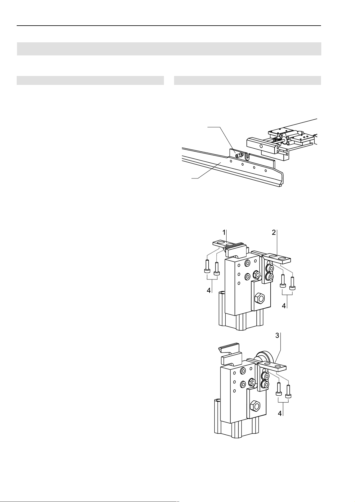
C.5
Short Seam Automat 2112-4 Working InstructionsBeisler Automated Sewing Equipment
Maintenance
C.5.4 Repairs
Clamp rail replacement:
The clamp rail must be replaced, when the protective coating underside the clamp rail is friction used.
Clamp rail removal:
1. Lift main clamp.
2. Loosen retaining screw 1 .
3. Pull clamp rail 2 down and remove.
Clamp rail installation:
1. Insert clamp rail 2 into fixture and push up until it reaches the stop. Make sure the clamp rail is positioned
evenly in the fixture.
2. Tighten retaining screw 1.
Cutter replacement:
The cutters are integral to a block together with the pressure cylinder. The cutter block for the left slash selvage
is attached with two fixing angles 1 and2 and screws
to the pick-up plate bracket.
The two cutter blocks for the left and right trousers components are each attached with a fixing angle 3 and
screws to the bottom of the working plate.
1. Disconnect compressed air hoses (the hoses are
merely pushed onto the sleeve).
2. Fig. 10: Remove retaining screws 4.
3. Position new cutter block, secure using screws and
connect compressed air hoses.
4. Readjust cutter position as described in Section 5.5,
"Machine set-up".
Fig. 9/10
Fig. 9
1
2
Fig. 10
- C 50 -
Page 51
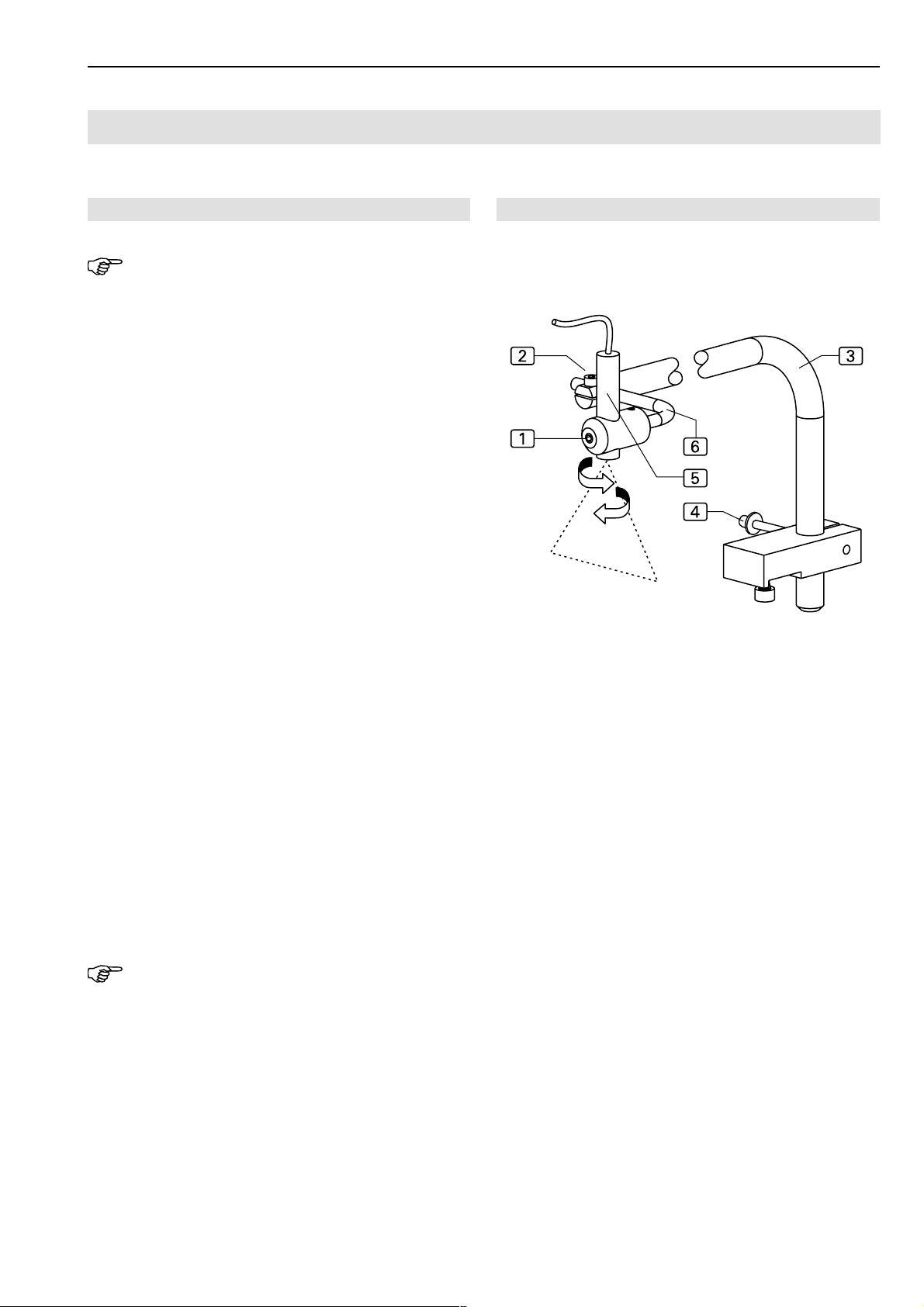
Short Seam Automat 2112-4 Working Instructions
Maintenance
C.5
Beisler Automated Sewing Equipment
C.5.5 Machine set-up
NOTE - Activating inputs/outputs!
To allow for testing machine movements or interval operation, the individual stages of movement can be activated with the inputs/outputs of the machine control unit (see
programming instructions, Section D.4.3., Service menu
level 1).
Usually, the setting up of the machine is controlled by
parameter values of the sewing programs (special parameters) and the parameter values of the machine control
unit (global parameters). The following mechanical modifications may be required additionally to ensure correct
seams with the set parameter values.
Guide laser adjustment:
The guide laser marks the line-up position of the left and
right trousers components parallel to folder and pick-up
plate. The position of the guide laser can be adjusted vertically and horizontally.
Adjusting the bracket height:
1.Fig. 11: Loosen retaining screw 4 at rear of worktable.
2. Position laser light bracket 3 in the desired height.
3. Tighten retaining screw 4.
Fig. 11
Fig. 11
Horizontal adjustment:
1. Loosen lock screw 1.
2. Rotate laser light 5 to desired position.
3. Tighten lock screw 1.
Vertical adjustment for tilting the laser light into the desired position:
1. Loosen lock screw 2.
2. Rotate laser light angular bracket 6 to desired position.
3. Tighten lock screw 2.
NOTE - Seam width!
The seam width can be determined by the vertical alignment of the guide laser when sewing the slash selvage.
If the alignment of the laser to the left is changed, the seam
narrows, if the alignment of the laser to the right is changed,
the seam becomes wider.
- C 51 -
Page 52
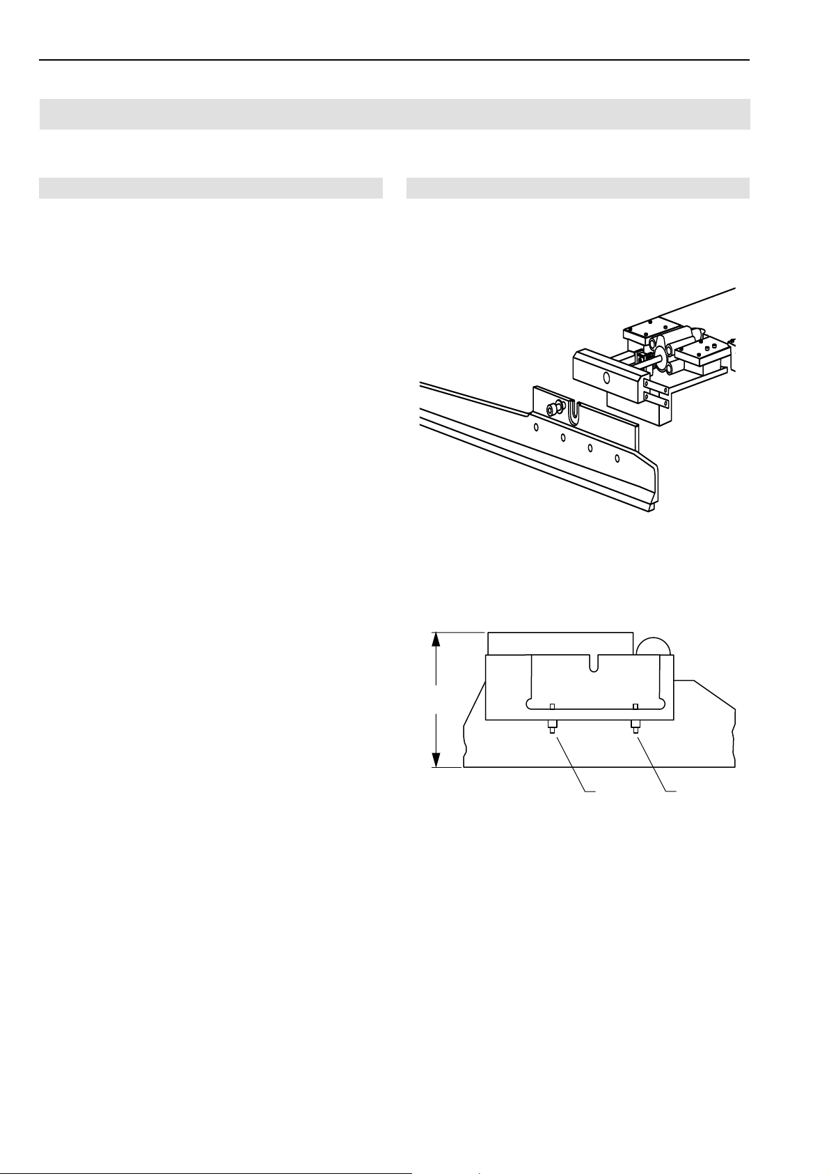
C.5
Short Seam Automat 2112-4 Working InstructionsBeisler Automated Sewing Equipment
Maintenance
C.5.5 Machine set-up
Adjusting clamp rail to machine function:
The machine is equipped with two different clamp rail versions. Depending on the machine function performed, the
corresponding clamp rail must be installed.
• For the function "Tucking pocket edge to pocket bag",
the clamp rail 2 with the plain support is required.
• For the function "Sewing on slash selvages", the clamp
rail3 with the cranked support is required.
Clamp rail removal:
1. Lift main clamp.
2. Fig. 12: Loosen and partially remove retaining screw 1.
3. Pull clamp rail 2 or 3 downward.
Clamp rail installation:
1. Insert clamp rail into receptacle and push all the way
up. Make sure that the clamp rail is flush with the receptacle.
2. Tighten retaining screw 1.
Clamp rail clamping pressure adjustment:
After any works to the main clamp, the clamping pressure
and the alignment of the clamp rail to the needle must be
checked.
1. Check to see if the main clamp exerts pressure to the
sewing piece evenly along the entire length of the rail
by lining up a piece of fabric to the insertion position
and lowering the main clamp.
2. Check clamping pressure by trying to pull the sewing
piece out of the clamp at several locations along the
clamp rail.
3. Fig. 13: If the pressure force is uneven or insufficient,
remove clamp rail and change the position of the two
adjusting screws 1 at the inner side of the clamp rail.
If the adjusting screws are screwed in, the pressure of
the clamp rail onto the working plate increases as the
height H of the main clamp in the downward direction
changes.
4. Repeat adjustment and recheck with lowered main
clamp until clamping pressure is distributed evenly along the entire length of the clamp rail.
Fig. 12
Fig. 13
H
1
Fig. 12/13
1
- C 52 -
Page 53
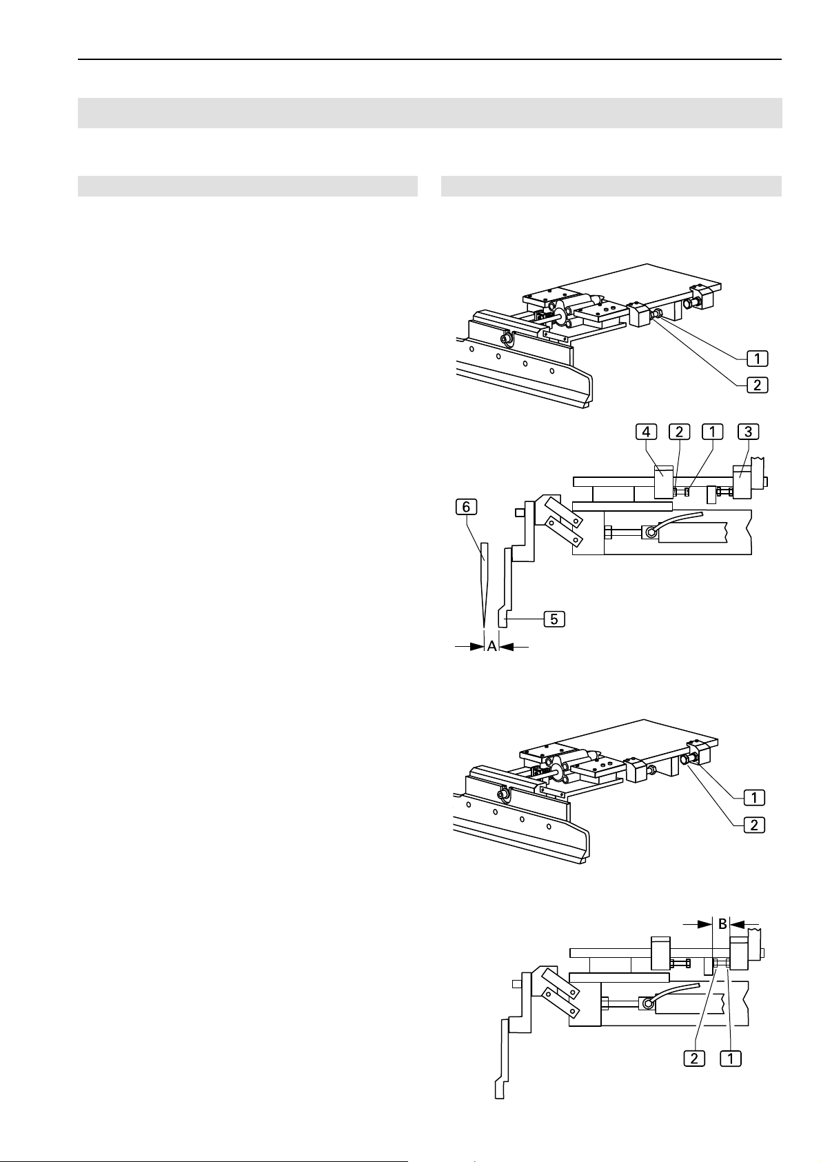
Short Seam Automat 2112-4 Working Instructions
Maintenance
C.5
Beisler Automated Sewing Equipment
C.5.5 Machine set-up
Adjustment of clamp slide disengagement position:
The disengagement position for the front and rear stop
point of the clamp slide is set at the pedestal.
The front stop point 4 determines how far the clamp slide
will approach the needle of the sewing head, the rear stop
point3 determines how far the clamp slide will return to
its start position.
Front stop point adjustment:
1. Lower main clamp.
2. Depressurize the machine. Disconnect compressed air
supply hose from on-site compressed air supply system.
3. Move main clamp by hand below sewing head and lower needle using handwheel.
4. Fig. 14: Distance A between clamp rail 5 and needle
6
must be 1-1.5 mm.
5. Loosen lock nut 2 of stop screw 1 at pedestal and
rotate stop screw to the desired position.
6. Check distance A .
7. Tighten lock nut 2 of stop screw 1.
Fig. 14/15
Fig. 14
Adjust rear stop point:
The rear stop point is adjusted correctly, if the clear length
B of the stop screw measures exactly 6 mm.
1. Fig. 15: Loosen lock nut 1 of stop screw 2 and rotate stop screw to the desired position.
2. Check length B.
3. Tighten lock nut 2 of stop screw 1.
Fig. 15
- C 53 -
Page 54
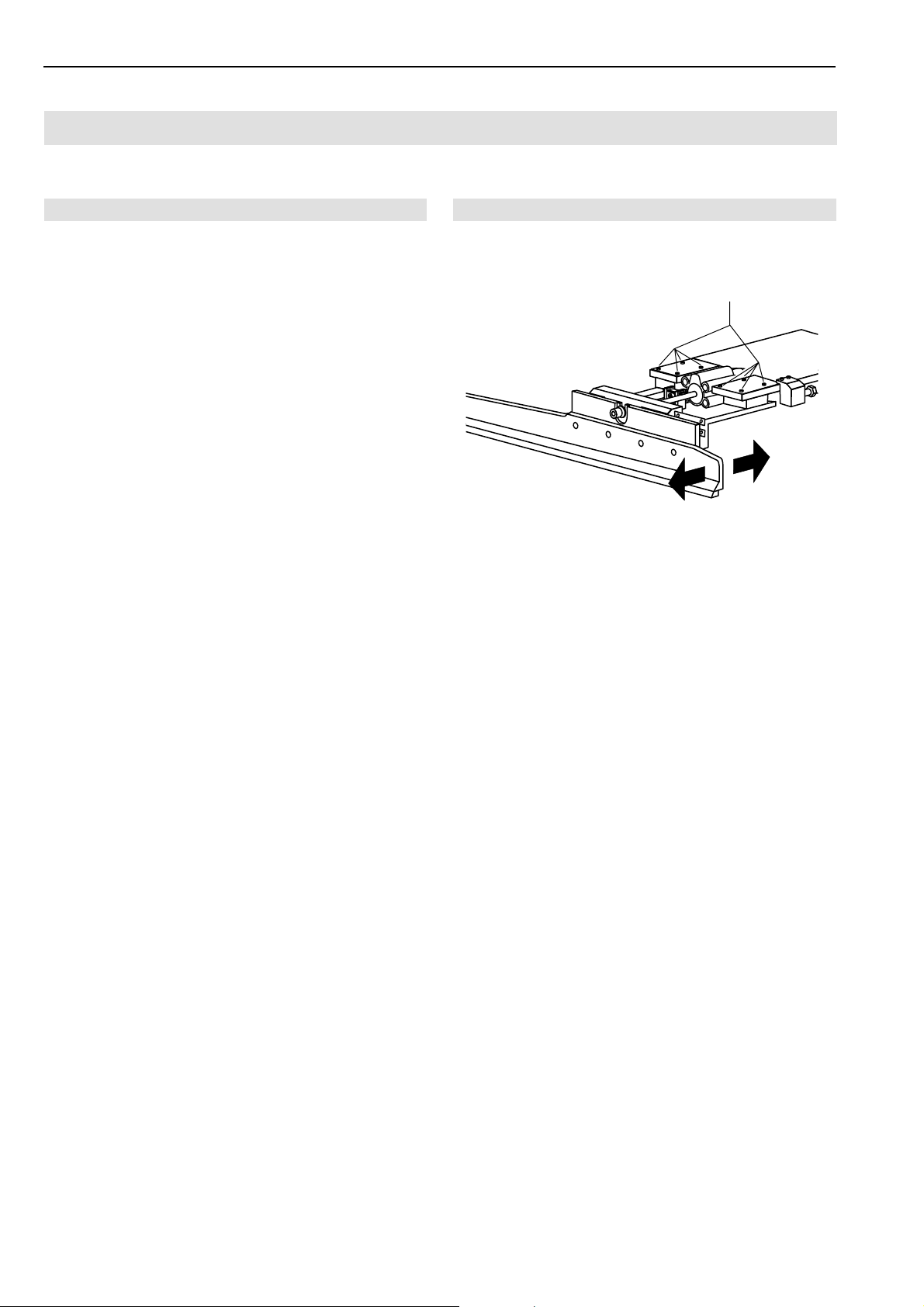
C.5
Short Seam Automat 2112-4 Working InstructionsBeisler Automated Sewing Equipment
Maintenance
C.5.5 Machine set-up
Adjustment of the clamp rail parallel orientation:
1. Check to see if the sewing head needle is positioned
exactly parallel to the clamp rail along the entire length
of the rail by moving the main clamp under the sewing
head and checking the distance between rail and needle at several locations.
2. Fig. 16: If distance is not identical at all locations, loosen
eight retaining screws 1 of clamp bracket and move
clamp rail to parallel position.
3. Tighten clamp bracket retaining screws and recheck
parallel orientation of clamp rail.
Fig. 16
Fig. 16
1
- C 54 -
Page 55
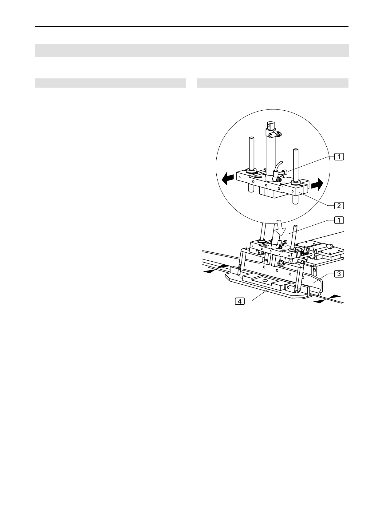
Short Seam Automat 2112-4 Working Instructions
Maintenance
C.5
Beisler Automated Sewing Equipment
C.5.5 Machine set-up
Folder to clamp rail alignment:
The lowered folder must be absolutely parallel to and in
slight contact with the clamp rail along its entire length.
Folder position adjustment:
1. Move main clamp to position using input/output control functions:
• Lower main clamp.
2. Move folder to position using input/output control functions:
• Rotate folder.
• Close folder clamp.
• Lower folder.
3. Fig. 17: Check parallel alignment of folder clamp
to clamp rail 3. To change the folder clamp alignment:
4. Loosen lock screw 1.
5. Rotate folder clamp bracket 2 to parallel position.
6. Tighten lock screw 1.
4
Fig. 17
Fig. 17
- C 55 -
Page 56
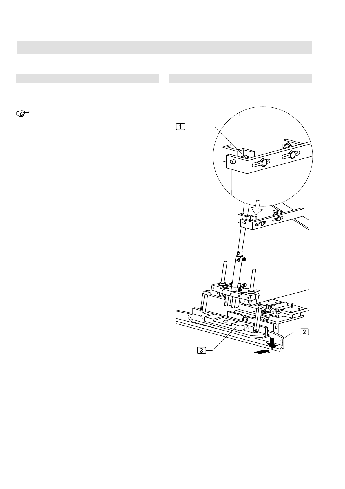
C.5
Short Seam Automat 2112-4 Working InstructionsBeisler Automated Sewing Equipment
Maintenance
C.5.5 Machine set-up
Folder lower position adjustment:
NOTE - Check folder lower position!
When positioned correctly, the folder must lower to the
working surface with slight friction contact to the left of the
clamp slide.
1. Set folder position stop. Loosen stop screw lock nut
at bracket and rotate stop screw to the desired position.
2. Check distance between folder 3 and clamp rail 2.
3. Tighten stop screw lock nut.
1
Fig. 18
Fig. 18
- C 56 -
Page 57
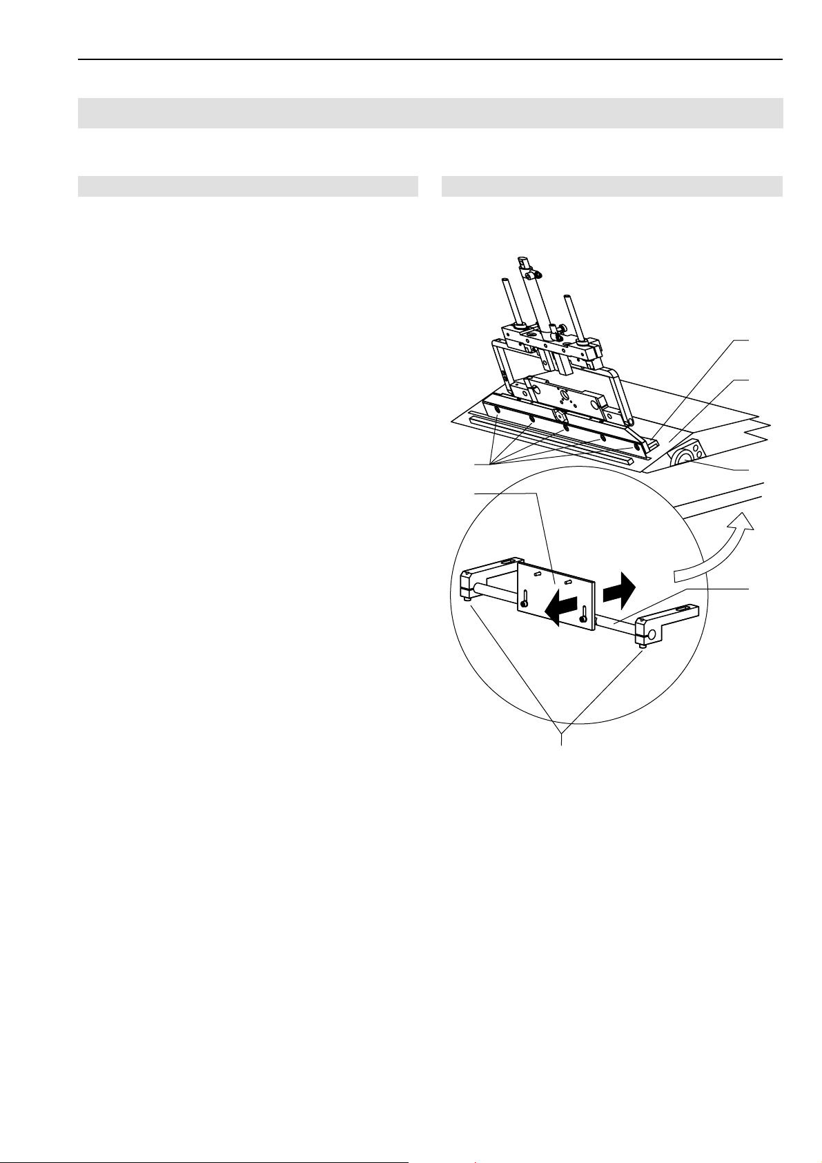
Short Seam Automat 2112-4 Working Instructions
Maintenance
C.5
Beisler Automated Sewing Equipment
C.5.5 Machine set-up
Folder to pick-up plate alignment:
To ensure that the folder can pick up the pocket edge evenly, the folder must lie upon the pick-up plate along its entire
length.
Pick-up plate inclination adjustment:
1. Fasten pick-up plate by rotating handwheel 3 completely to minus range.
2. Move folder 1 to pick-up plate 2 using input/output
control functions:
• Move folder to right.
• Lower folder.
3. Adjust pick-up plate inclination so that the folder lies
absolutely even on the pick-up plate by loosening the
two retaining screws 5 of the pick-up plate bracket
6
on the worktable underside and rotate the bracket
at the holder 4.
4. Tighten retaining screws.
5. Readjust folder rail 1. Slightly loosen retaining screws
7
and depress folder rail evenly onto pick-up plate.
6. Tighten retaining screws 7.
Fig. 19
7
6
Fig. 19
1
2
3
4
- C 57 -
5
Page 58
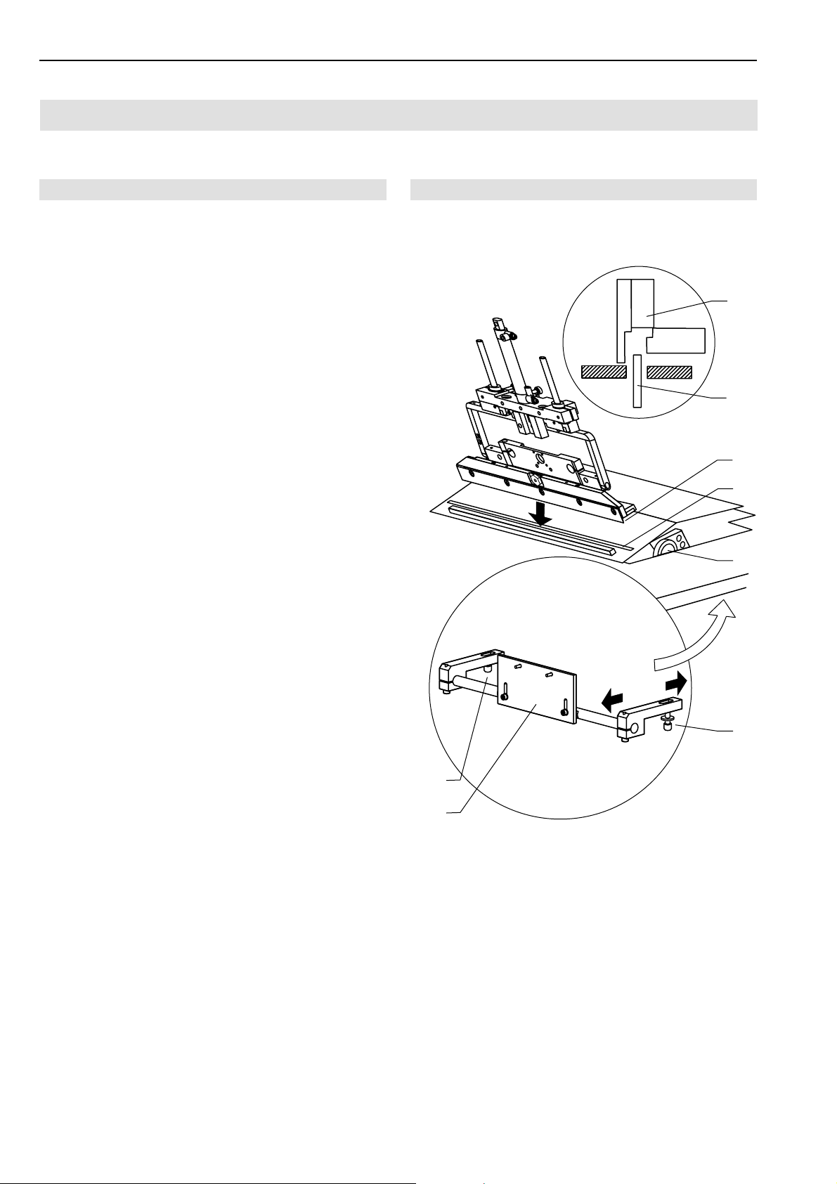
C.5
Short Seam Automat 2112-4 Working InstructionsBeisler Automated Sewing Equipment
Maintenance
C.5.5 Machine set-up
Folder bar to folder clamp alignment:
To ensure that the folder can crimp over the pocket edge
evenly, the folder clamp 1 must pe positioned centrically
above the folder bar 2.
Folder bar adjustment::
1. Fig. 20: Fasten pick-up plate by rotating handwheel
completely to minus range.
Loosen retaining screw 4 of folder bar bracket at the
worktable underside and reposition bracket 5.
2. Tighten retaining screw.
3
Fig. 20
Fig. 20
1
2
1
2
3
4
5
4
- C 58 -
Page 59
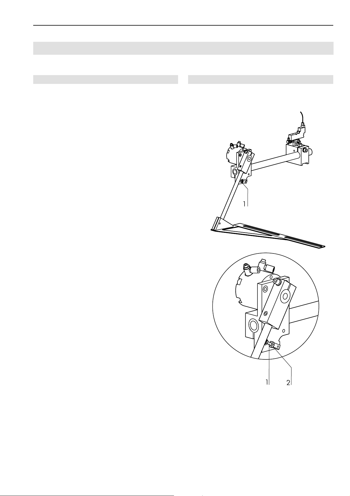
Short Seam Automat 2112-4 Working Instructions
Maintenance
C.5
Beisler Automated Sewing Equipment
C.5.5 Machine set-up
Right slash selvage stop alignment:
The position of the stop determines the line-up position
of the right slash selvage to the right trousers component.
Stop position adjustment:
Fig. 21: The end position of the stop is set using the ad-
justing screw 1.
2. Loosen locknut 2.
Rotate adjusting screw 1.
3. Tighten locknut.
Fig. 21
Fig. 21
- C 59 -
Page 60
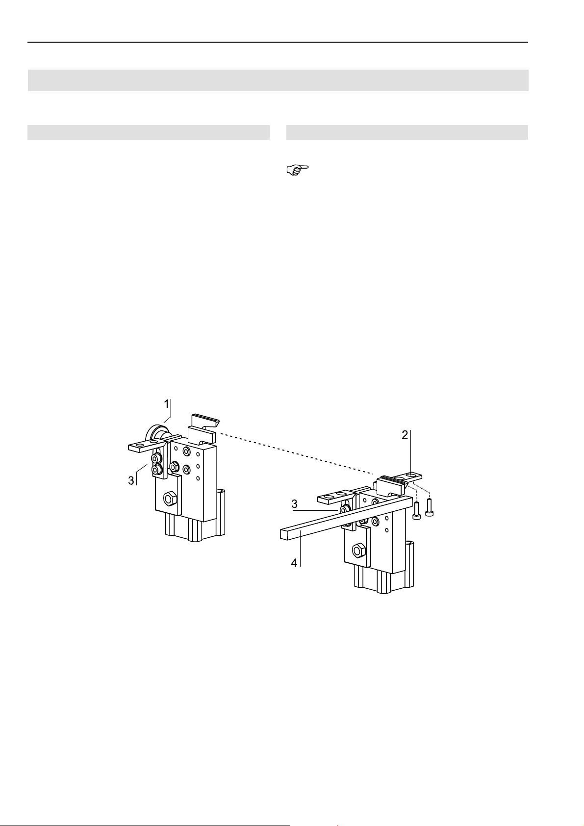
C.5
Short Seam Automat 2112-4 Working InstructionsBeisler Automated Sewing Equipment
Maintenance
C.5.5 Machine set-up
Cutter adjustment:
The depth of cut of the gusset is adjusted for all three cutters using different settings.
• The depth of cut of the two cutters of the working plate
for the gusset of the left and right trousers components
is changed by rotating the adjusting wheel 1.
• The depth of cut of the gusset in the left slash selvage depends on the cutter block's mounting position. The
mounting angles 2 have slots. By repositioning the
cutter block in the slots, the cutter can be positioned
at an exact distance to the stop rail 4 of the pick-up
plate.
• The vertical position of the cutters is set by repositioning
the cutter block in the slots of the vertical angle arm
3
. Note that the lowered cutters must be positioned
flush with the upper edge of the working plate or of the
pick-up plate.
Fig. 22
Fig. 22
NOTE - Cutting position alignment!
The two cutters for the gusset in the left slash selvage and
in the left trousers component must be aligned to each
other in a way that ensures that both cutting positions are
exactly flush.
- C 60 -
Page 61
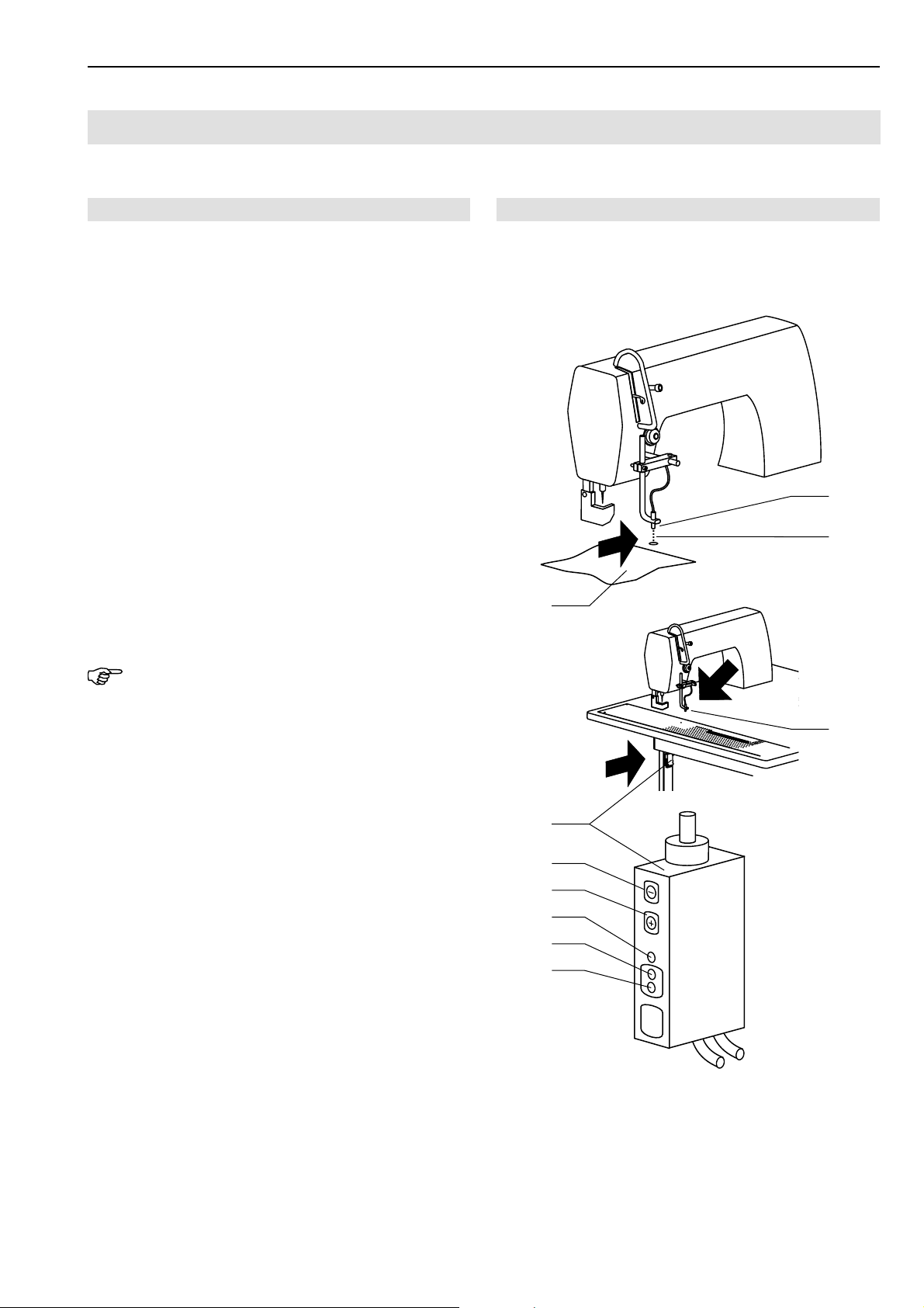
Short Seam Automat 2112-4 Working Instructions
Maintenance
C.5
Beisler Automated Sewing Equipment
C.5.5 Machine set-up
Photocell light sensitivity setting:
The photocell 1 at the sewing head controls the beginning and the end of the sewing process, provided that this
function has been enabled as described in Section D.4.9.
The sensitivity of the photocell must be set in accordance with the sewing material used.
1. Fig. 23: Make sure that the light beam 2 of the photocell is not interrupted.
2. Unlock the keypad:
Keep the two buttons 5 and6 (+ / -) depressed for
approx 5 seconds.
The green LED 8 illuminates momentarily to indicate
the unlocked state. The keypad remains unlocked for
4 minutes (red LED 7 flashes), then the light guide
controller is locked automatically.
3. Set sensitivity using buttons 5 and6:
Press + to increase sensitivity.
Press - to reduce sensitivity.
4. Interrupt light beam 2 with the sewing material to be
used3; if the yellow LED 9 fails to go off, reduce
sensitivity.
Fig. 23
Fig. 23
1
2
3
NOTE - Red LED!
The red LED7 must not illuminate in any switching state.
If the red LED illuminates, the light amplifier is in a critical switching state. In this case, increase the photocell sensitivity until the red LED goes off, then set the sensitivity
in accordance with the sewing material used as described above.
1
4
5
6
7
8
9
- C 61 -
Page 62
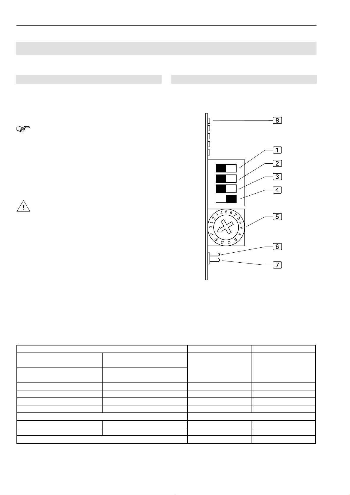
C.5
g
Short Seam Automat 2112-4 Working InstructionsBeisler Automated Sewing Equipment
Maintenance
C.5.5 Machine set-up
Installation stepper motor:
The PCB for controlling the stepper motor is installed in
the control box.
NOTE - Machine cycle!
To prevent moving machine parts from colliding with each
other or with other components when the machine is switched on again, move the machine manually into its start
position before the PCB is replaced.
1. Depressurize the compressed air system of the machine. Disconnect the compressed air hose of the machine from the on-site compressed air supply system.
2. Slide main clamp into start position.
CAUTION - Damage to electrical components!
The PCB switches must not be tampered with while
voltage is applied to the machine.
Otherwise, related electrical components may be
damaged or become unusable!
Disconnect machine from power supply system and
protect it against accidental reconnection.
Fig. 24
Fig. 24
Adjusting switches on the PCB:
1. Set step width:
• using DIP switches 1 and 2,
• micro step at hook switches 6 and 7.
2. Set current lowering using DIP switch 3.
3. DIP-switch 4 to ON
4. Set motor phase current, rotate switch 5 to F.
5. Switch on supply voltage. When the PCB is adjusted
correctly, the LED 8 (stand-by) is illuminated, the
stand-by relay is energized.
Micro step
Hook switch open
Signal = 0
Hook switch closed
Signal = 1
200 2000 ON OFF
400 4000 ON ON
500 5000 OFF ON
1000 100000 OFF OFF
nal 0 = deenergized, Signal 1 = energized
Si
Rotary switch position Phase current DIP switch 3 Current lowering
F5,50 AOFFON
Hook switch closed
Signal = 0
Hook switch 6 open
Signal = 1
DIP switch 1 DIP switch 2
ON OFF
- C 62 -
Page 63

Short Seam Automat 2112-4 Working Instructions
Maintenance
C.5
Beisler Automated Sewing Equipment
C.5.5 Machine set-up
Setting the thread cutter:
The three-digit value input (GP Par. 35) determines when
the thread cutter is activated.
The setting of the thread cutter must be checked during
machine operation and corrected as required.
1. Rotate sewing head handwheel in direction of machine
rotation until needle reaches highest point (pinning position C).
Lock handwheel at position C by depressing pinning
pin of hole to left of handwheel.
2. Abb. 25: Install drive belt 1 so that the shaft feather
key2 is flush with motor housing mark 3.
3. Unlock handwheel.
4. Call menu Global Parameters:
• Press key
• Press GP key
Insert the following values in Global Parameters:
35: Thread lever in position up 200 INC
36: Switch-on pos. for thread cutting 110 INC
Store value and exit setting level:
• Press key
5. Start the thread cutting function:
• Press key
Fig. 25
Fig. 25
• Press thread cutter key
Start or stop machine run:
• Press key
6. Check position C to see if shaft feather key 2 is flush
with motor housing mark 3.
If required, change values and test thread cutting function.
7. Start thread cutting and recheck positions.
• Press diagnostics key
• Press sewing motor key
- C 63 -
Page 64
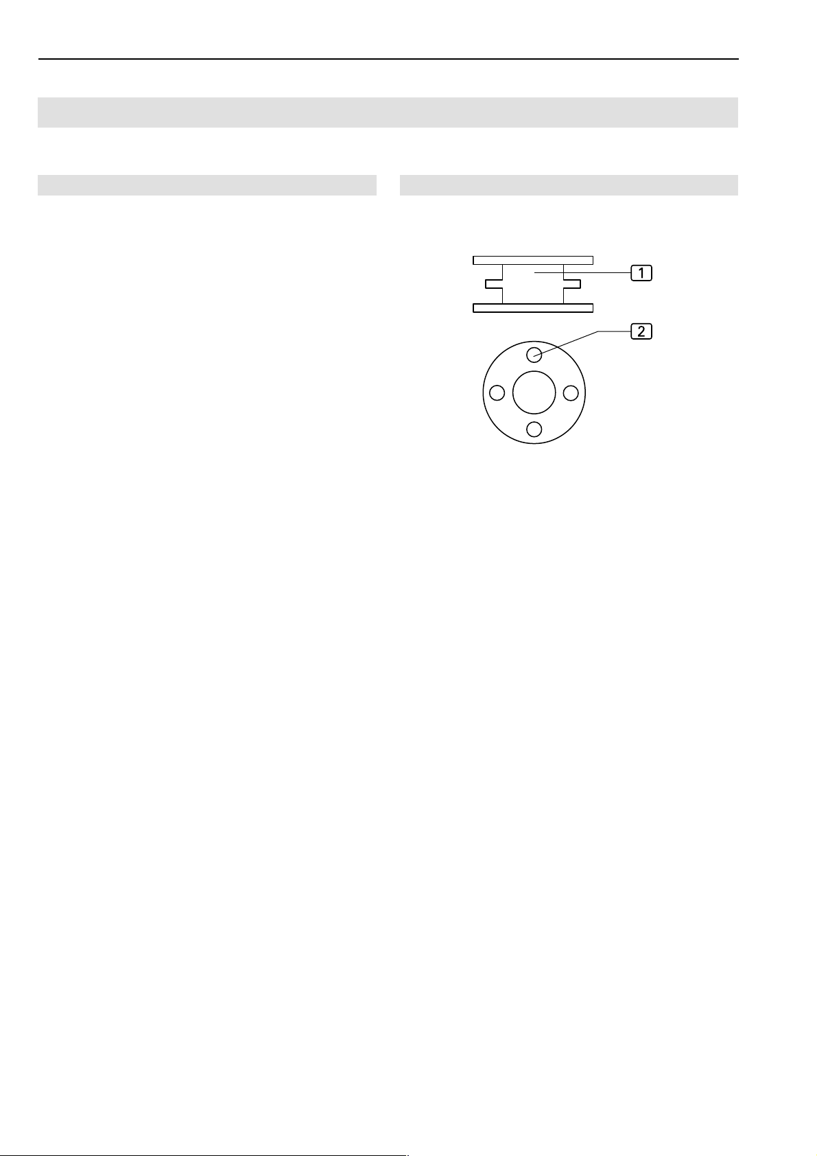
C.5
Short Seam Automat 2112-4 Working InstructionsBeisler Automated Sewing Equipment
Maintenance
C.5.5 Machine set-up
Checking the rest thread monitor:
The rest thread monitor is checked using a photocell. If
the messages on the display do not match the filling state
of the spool, the photocell sensitivity must be checked.
1. Fill bobbin to half its capacity so that filling state indicators2 of upper chamber 1 are covered.
2. Insert bobbin and sew until display shows: BOBBIN:
004 m.
Keep sewing until display shows: BOBBIN EMPTY
3. Remove spool, unwind rest thread and measure remaining length (should be 0.5 m).
Adjusting the photocell:
• If the thread on the spool is sewn off over the rest length
of 0.5 m without the message BOBBIN EMPTY being
displayed, the photocell sensitivity must be increased:
• Rotate potentiometer at photocell in clockwise direction.
• If the message BOBBIN EMPTY is displayed even
though the spool contains more than 0.5 m thread, the
photocell sensitivity must be reduced:
• Rotate potentiometer at photocell in counter-clockwise direction.
Fig. 26
Fig. 26
- C 64 -
Page 65
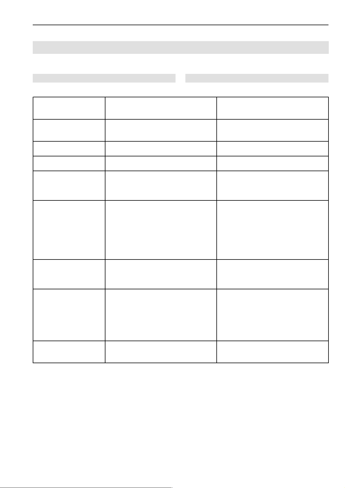
Short Seam Automat 2112-4 Working Instructions
Troubleshooting
C.6
Beisler Automated Sewing Equipment
Error 01:
„Sewing program empty“
Error 02 :
„Seam not enabled“
Error 04 :
„Clamp in wrong position“
Error 05 :
„I/O communication error“
Error 06 :
„Position not valid“
Error 07:
„No pulses from clamp
motor“
Error 08:
„Main clamp at the stopper“
Error 09:
„Clamp can not leave the
switch“
Error 12:
„Safety photocell not
lighted“
Current sewing program empty; possibly
distances and routes have not been input or
the entire program was erased
Current sewing program not ac tivated;
number appears black on white
Real value pulse from clamp motor does
not correspond with nominal value
Error transmitted between control unit and
I/O module
Clamp slide not positioned correctly Check sensor connection to clamp motor;
No position pulse from clamp motor. If the
clamp motor moved slightly, the pulses
could not be processed properly. If the
motor did not move, problem may be
caused by control unit or clamp motor
power unit
Limit switch ES04 switched during clamp
movement even though clamp should have
been distant still
Clamp slide moves to limit switch during
initialization but does not return (direction
not reversed)
No reflection for FZ 20 (safety) Replace reflective film; check photocell
Insert program values manually, copy from
other program or retrieve from ROM
(parameter INIT)
Press <ENT> key to activate program
Reduce current for clamp motor to MAX
clamping pressure
Check connecting cable; if OK, replace
control unit and/or I/O module
check connecting c able between adapter
board 9020020 and I/O module 9020013;
replace adapter board 9020020
Check connection to clamp motor; replace
clamp motor; replace adapter board
9020020; check condition of LEDs at power
board (Berger); if required, check Berger
motor; check connec tion to clamp motor
(plug); check connection between 9020020
and power unit (plug); replac e adapter
board 9020020
Check distance c ounter using test program
(steps); if counter is faulty, replace clamp
motor or adapter board 9020020; if counter
is OK, check switch 04
Using test program ‘Clamp motor
actuation’, enter slow speed and reverse
direction using arrow key s; if motor does
not reverse direction, check: connection
between 9020020 and power unit (plug);
Berger power unit; if motor reverses
direction, check limit switch ES04
(input)
- C 65 -
Page 66
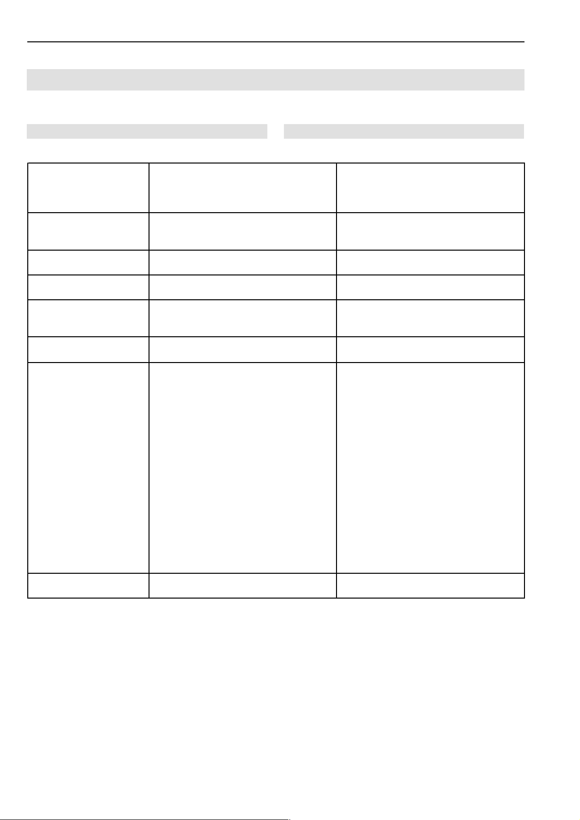
C.6
Short Seam Automat 2112-4 Working InstructionsBeisler Automated Sewing Equipment
Troubleshooting
Error 13:
„Clamp position error“
Error 14:
„Insertion/sewing length
error“
Error 15:
„Switch for curve start“
Error 16:
„Folder not left“
Error 21:
„Folder not sideways“
Error 22:
„Clamp/curve wrong“
Error 29:
„No pulses from sewing
motor“
Error 30:
„Sewing motor too fast“
Excessive difference between nominal
position (step motor default) and actual
position (pulse from incrimental sensor) of
clamp slide; clamp slide probably blocked
Sewing length exceeds maximum possible
sewing distance; excessive insertion
distance
ES12 (curve start slope) does not switch
or switches too late
ES08 (folder at left stop) does not switch or
switches too late
ES05 (clamp movement sideways) does
not switch or switches too late
Clamp does not correspond with curve Clamp safety switch (ES15/16) not
No pulse from sewing motor after sewing
process starts (sewing motor does not run)
During thread cutting, sewing motor did not
reach cutting speed within error period
Remove blocked component; check clamp
slide for easy movement; check motor
pinion (may be loose on shaft); tension
transport belt
Program sewing distance / insertion
distance correctly
Check ES12 (input); check mechanical
components for easy movement
Check ES08 (input); check mechanical
components for easy movement
Check ES05 (input); check mechanical
components for easy movement
identical with curve safety switch (ES13/14)
Check sewing motor and synchronization;
check connection between I/O module
9020013 and sewing motor; read both
upper LEDs at 9020013: left LED
illuminates briefly when needle up; right
LED shows synchronization pulses (512
pulses/rotation); if no LED illuminates when
handwheel is actuated, c heck sewing
motor power supply and replace sewing
motor, if required. If LEDs are OK and
motor does not run before error mess ages,
check connection between 9020020 and
sewing motor, replace 9020020 or sewing
motor, if required; if motor makes some
stitches before error message, check
connection between control unit and I/O
module, replace components as required
Replace sewing motor or synchronizer
- C 66 -
Page 67
Short Seam Automat 2112-4 Working Instructions
Troubleshooting
C.6
Beisler Automated Sewing Equipment
Error 32:
„Thread position does not
come“
Error 33:
„Sewing motor does not
stop“
Error 34:
„Needle not up“
Error 35:
„Thread breakage“
Error 37:
„Thread only rest“
Error 41:
„No parts“
Error 42:
„Photocell not lighted“
Error 43:
„Photocell lighted too early“
Error 45 ... 48:
“I/O DAC, ULN, 485, RES”
During thread cutting, sewing motor did not
reach cutting position
After thread cutting, sewing motor does not
stop within error period
Needle not in upper rest position; when the
error message is issued, the control unit
attempts once more to move the needle to
the upper position
Thread monitor detects thread breakage
The photocell at the spool case is
illuminated, spool empty
Photocell FZ21 remains illuminated during
insertion
Photocell FZ21 does not detect end of
seam
Photocell FZ21 detects intermittent
reflection during insertion
Internal hardware error during data
transmiss ion to adapter board 9020020
Input slower cutting speed and earlier
cutting position; replace s ewing motor or
synchronizer
Input slower cutting speed and earlier
cutting position; replace s ewing motor or
synchronizer
Check sewing motor and synchronizer;
check connection between 9020013 and
sewing motor; read condition of two upper
LEDs at 9020013: if no LED illuminates
when handwheel is rotated, check sewing
motor power supply; replace s ewing motor
if required; if LEDs are OK, check
connection between 9020020 and sewing
motor; replace 9020020 if required
If spool is not empty, the photocell is
maladjusted (response too sensible); adjust
correctly
Adjust photocell sensibility; input test 21
Sewing distance too long; adjust photocell
sensibility; input test 21
Adjust photocell sensibility; input test 21
Replace 9020020
- C 67 -
Page 68

C.7
Short Seam Automat 2112-4 Working InstructionsBeisler Automated Sewing Equipment
Specifications
Power supply
Supply voltage 230 V ±10 %, 50/60 Hz
Connection to supply (1, N, PE) AC
Power consumption 1.3 kW
Fusing 16 A
Dimensions of the machine
Width x Depth x Height in mm 1700 x 1400 x 1700
Table height
Adjustable height in mm 790 - 1240
Weight
Overall weight approx 210 kg
Compressed air
Operating pressure 6 bar
Quality oil-free
Air consumption 12 NL
Vacuum
Displacement (minimum) 130 m³/h
- C 68 -
Page 69

Short Seam Automat 2112-4 Working Instructions Beisler Automated Sewing Equipment
Section D
Programming Instructions
- D 69 -
Page 70

Beisler Automated Sewing Equipment
Short Seam Automat 2112-4 Working Instructions
Programming Instructions
Section D
Contents
D.1 Operating panel ................................................................................................................. 72
D.1.1 Display and key functions .............................................................................................. 72
D.2 Fundamentals of programming ....................................................................................... 72
D.2.1 Program control layout ................................................................................................... 73
D.2.2 Program level overview .................................................................................................. 75
D.3 Programming .....................................................................................................................76
D.3.1 System menu ................................................................................................................. 76
Entering the service code ....................................................................................... 76
Testing clamp motor steps ......................................................................................76
Setting clamp travel steps ....................................................................................... 77
Displaying total piece counter ................................................................................. 77
Eprom seam parameters ........................................................................................ 77
Creating seam program ..........................................................................................78
Setting the seam sequence .................................................................................... 78
Erasing seams ........................................................................................................ 79
Copying seam numbers .......................................................................................... 79
Entering seam names ............................................................................................. 80
Copying sewing programs to the memory card...................................................... 80
Loading sewing programs from the memory card .................................................. 80
D.3.2 Service menu start level ................................................................................................ 81
Loading variables from the memory card ...............................................................81
Running clamp motor in permanent test ................................................................ 81
Testing the thread cutter ......................................................................................... 81
Entering mechanic code ......................................................................................... 81
Requesting service menu level 1............................................................................ 82
Insertion distance length, photocell correction for beginning of seam ................... 82
Photocell correction for end of seam, seam length and fixed seam end point ...... 83
Removing sewing pieces from the stacker ............................................................. 83
Moving the sliding table .......................................................................................... 83
Manual actuation of the thread clamp .................................................................... 83
Manual testing of the cutters .................................................................................. 85
Filling spool ............................................................................................................. 85
Resetting the insertion process .............................................................................. 85
D.3.3 Service menu level 1 ......................................................................................................85
Setting the seam sequence .................................................................................... 85
Resetting the day counter to zero........................................................................... 85
Manual winding ....................................................................................................... 87
Selecting machine control inputs / outputs ............................................................. 87
D.3.4 List of inputs and outputs ............................................................................................... 87
D.3.5 Global parameters.......................................................................................................... 88
Requesting / exiting the global parameter menu.................................................... 88
D.3.6 List of global parameters ................................................................................................ 89
D.3.6 List of global parameters ................................................................................................ 90
D.3.7 List of special parameters .............................................................................................. 91
Request / exit special parameter menu .................................................................. 91
- D 70 -
Page 71

Short Seam Automat 2112-4 Working Instructions Beisler Automated Sewing Equipment
Programming Instructions
Section D
Contents
D.3.8 Level 2 special parameters / Functions ......................................................................... 93
Enabling / disabling functions .................................................................................93
D.3.9 Level 3 special parameters / Functions ......................................................................... 94
Switching photocell for beginning of seam on or off .............................................. 94
Switching photocell for end of seam on or off ........................................................ 94
Switching folder on or off ........................................................................................ 94
Switching sliding table on or off .............................................................................. 94
D.3.10 Level 4 special parameters / Functions ....................................................................... 95
Enabling or disabling vacuum ................................................................................. 95
Enabling or disabling cutters .................................................................................. 95
Sewing to fixed end-of-seam position .................................................................... 95
D.3.11 Level 5 special parameters / Functions ........................................................................ 96
Switching the top thread monitor on or off.............................................................. 96
Switching the rest thread monitor or bottom thread monitor on or off ................... 96
Switching clamp position after end of seam on or off............................................. 96
n Moving clamp to waiting position ......................................................................... 96
Scissors pick-up plate (left side pocket) .................................................................96
D.3.12 Level 2 special parameters / Lists ................................................................................ 97
Selecting start modes ............................................................................................. 97
Setting upper part parameters ................................................................................ 98
Setting stitch lengths and bar tacks ........................................................................ 98
Parameters for clamp transport ..............................................................................98
D.4 Factory settings................................................................................................................. 99
D.4.1 Factory settings global parameters ................................................................................ 99
M 01 global parameters 2112-4 .............................................................................. 99
D.4.2 Factory settings special parameters ............................................................................ 100
M 01 Special parameters-1 / 2112-4..................................................................... 100
M 01 Special parameters-2 / 2112-4..................................................................... 101
M 01 Special parameters-3 / 2112-4..................................................................... 102
- D 71 -
Page 72
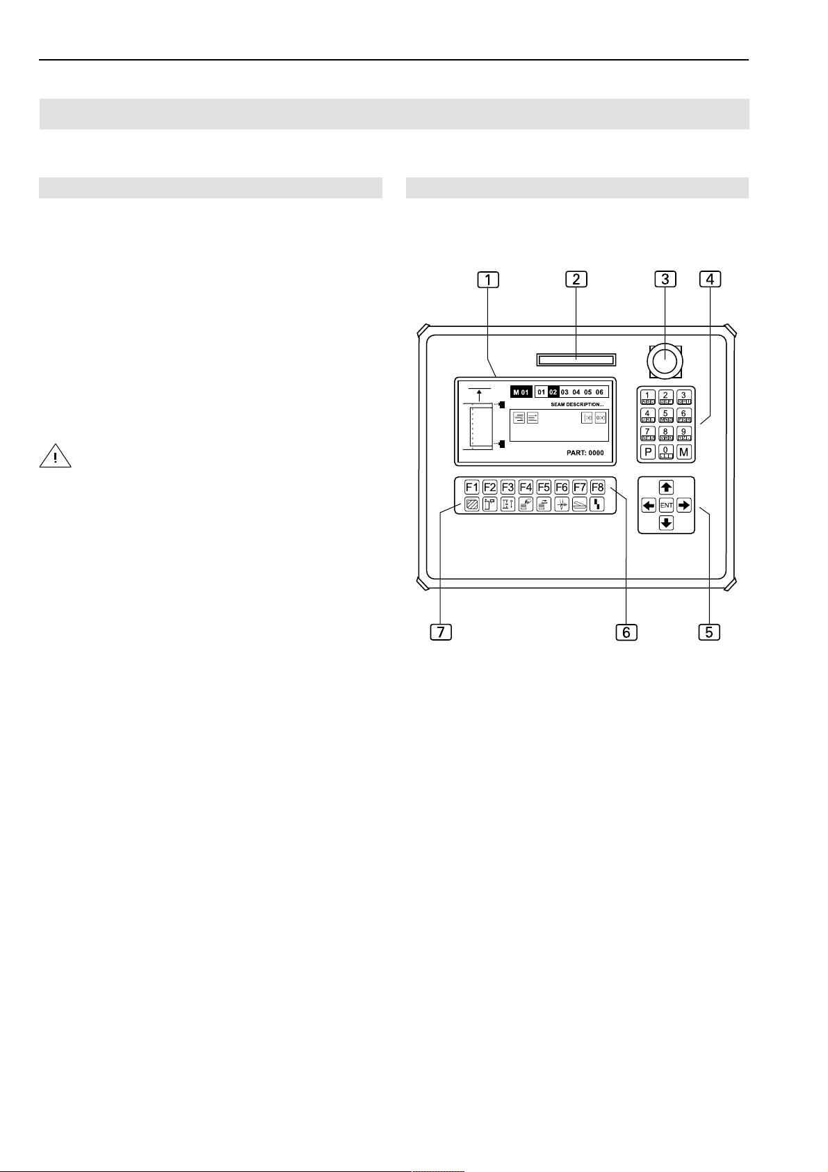
Beisler Automated Sewing Equipment
Operating panel
D.1
Short Seam Automat 2112-4 Working Instructions
D.1.1 Display and key functions
1
Display
During machine operation, the display shows the
values of the selected sewing program. If menus
are activated, the menu symbols or the corresponding parameters of the function are displayed
2
Slot for memory card
The memory card is the storage medium for bakkup copies of all program control data. Programs
can be copied to and stored on the memory card
and loaded into the machine control unit if required.
CAUTION - Data loss!
The memory card requires permanent current from a
battery to store data. If power supply is interrupted,
data will be lost completely.
Do not remove battery from memory card!
• Battery life is about 3 years; after this time, the battery must be replaced.
Fig. 1
Fig. 01
3
Program stop switch
If the switch is pressed during machine operation,
all machine movements and the sewing process
are stopped.
4
Numeric keypad
All variable number values are entered using the
numeric keypad.
The desired sewing programs are requested using
the M key. The P key is used to request submenus, to confirm input and to exit the programming
mode.
5
All arrow keys
Pressing the UP or DOWN arrow key will move
the cursor one line up or down in the selected
menu.
Pressing the LEFT or RIGHT arrow key will either
mark the desired parameter or, if the parameter
list comprises several pages, browse forward or
backward.
6
Function keys
The function keys are used to request the menus
on the selected level for setting or changing machine functions.
Two function keys have an identical function in all
selectable menus.
To move to the previous level or to the start level
and to move to the next level:
&,
Press or key.
7
Symbol bar
The symbol bar indicates the menus that can be
requested using function keys 6 directly from the
start level.
For all other menus, the corresponding symbols
are shown on the operating panel display.
- D 72 -
Page 73

Short Seam Automat 2112-4 Working Instructions Beisler Automated Sewing Equipment
Fundamentals of programming
D.2
D.2.1 Program control layout
The program control is controlled using four different kinds
of menus:
1. System menu,
2. Service menu,
3. Global parameter menu,
4. Special parameter menu.
System menu
The system menu is used to perform all settings for the
program control operating system and for managing the
sewing programs:
• Copying factory settings to the program control unit,
• Saving programmed sewing programs to the memory card,
• Copying and renaming sewing programs,
• Copying sewing programs from the memory card to the
program control unit.
Service menu
The service menu is used to directly request service functions. These functions support machine set-up or other
works required during machine operation, e.g. resetting
the day counter or winding the bottom thread.
Global parameter menu
This menu is used exclusively for setting the global parameters, i.e. parameters that control the basic functions
of the machine. Changing global parameters will result in
changes of seams of all stored sewing programs (e.g. time
for blowing off a finished sewing piece using compressed
air).
Special parameter menu
Special parameters are settings that refer only to one particular seam of a sewing program. Changing a special parameter will affect only the currently selected seam for
which a setting is made (e.g. stitch length of a seam).
The special parameter menu consists of several submenus.
Special parameters can be functions that are enabled or
disabled as required or parameter values that are set in
lists.
Sewing program
A sewing program controls the entire machine operation
during production:
• transport of the sewing piece to the sewing head,
• tucking of a seam and
• ejection of the sewing piece.
A sewing program is determined by two different kinds of
values:
• global parameters,
• special parameters.
Sewing programs can be copied or renamed.
Seam number
Each sewing program can be executed with up to six
seams of different stitch widths. The seams are assigned
to the sewing program by seam numbers (01, 02, 03, 04,
05, 06).
The numeric string of the two-digit seam number is freely selectable.
Combination sewing program with seam
A sewing prgram can be combined with one seam, with
several seams or with all six seams.
If a sewing program with several seam numbers is requested, the seams are effected in the sequence of the seam
numbers from left to right.
The sequence of the seam number is freely selectable.
Memory
Sewing programs are stored in the memory (M).
The program control memory can contain up to 50 sewing
programs (M 01-M 50) with up to six seams (01, 02, 03,
04, 05, 06) each.
All sewing programs stored in the memory can be copied
to the memory card (backup copies).
Creating sewing programs
Basically, it is possible to create entirely new sewing programs; however, it is easier to:
• copy a factory-programmed sewing program to an unused location in the memory and to modify this program,
• copy an already modified sewing program to an unused location in the memory and to adapt it further in
accordance with the intended purpose.
- D 73 -
Page 74

Beisler Automated Sewing Equipment
Fundamentals of programming
D.2
D.2.1 Program control layout
Short Seam Automat 2112-4 Working Instructions
Access to menus
The following menus are freely accessible:
• Service menu,
• Global parameter menu,
• Special parameter menu.
Except for three submenu pages, the entire system menu
is controlled by access privileges. These privileges protect the system menu from unauthorized access. Data
cannot be entered and the system menu cannot be modified unless the service code is entered. This code is
contained in the documentation delivered with the machine.
Menu level structure
The program control is divided into six menu levels (start
level and levels 1-5).
The system menu is requested from the start level. The
remaining operator prompting is achieved with plain text
in the submenus.
The service menus are requested directly from the start
level and from level 1.
The global parameter menu is requested from level 1,
the parameters pertaining to the menu are selected and
changed in a list.
The special parameter menu is requested from level 1
and is edited in four other levels (levels 2-5) and in the pertaining parameter lists.
CAUTION - Damage to machine!
Some of the menu entries start machine units or a
machine cycle.
This may damage machine components if the machine
is not ready for operation.
Do not enter data unless the machine is ready for
operation.
Factory settings
The machine comes with a factory-installed standard program (M 01) with five seams (01, 02, 03, 04, 05) and M02
(11,12) and M03 (15,16).
The seams of M01 differ in their control functions by sewing pocket edge and pocket bag:
• Seam 1: The beginning and the end of the seam are
determined by the scan points of the photocell.
• Seam 2: The beginning of the seam is determined by
the scan point of the photocell, the end of the seam is
determined by a fixed seam length.
• Seam 3: The beginning of the seam is determined by
a fixed insertion distance, the end of the seam is determined by the scan point of the photocell.
• Seam 4: The beginning of the seam is determined by
a fixed insertion distance, the end of the seam is determined by a fixed seam length.
• Seam 5: Manual controled seam.
The two seams M 02 differ by their combination of functions that are required for performing the seam.
• Seam (11) controls the procedure for sewing the slash
selvage to the right trousers component.
• Seam (12) comprises the function for crimping over the
left slash selvage, for the automatic positioning of the
slash selvage onto the left trousers component and for
the subsequent tucking of the two sewing pieces.
The two seams M 03 differ as well by their combination
of functions that are required for performing the seam.
• Seam (15) controls the procedure for sewing the side
pocket to the right trousers component.
• Seam (16) controls the procedure for sewing the side
pocket to the left trousers component.
- D 74 -
Page 75
Short Seam Automat 2112-4 Working Instructions Beisler Automated Sewing Equipment
Fundamentals of programming
D.2
D.2.2 Program level overview
(
System menu
(Submenus)
Global parameter menu
(Parameter list)
Fig. 2
abcdefgh
Start level
jkrmno#q
Service menu
(Direct access)
ABCD FGH
Level 1
abcdefgh
Special parameter menu
(Operating levels with functions/parameter lists)
AIJKLM
abcdefgh
ANOP SQRX
abcdefgh
AT ÜÖÄYSU
abcdefgh
A VW Z?#
abcdefgh
Level 2
Level 3
Level 4
Level 5
- D 75 -
Page 76

Beisler Automated Sewing Equipment
Programming
D.3
D.3.1 System menu
Short Seam Automat 2112-4 Working Instructions
The system menu is divided into several submenus. The
submenus themselves are divided into access-protected
and open submenus. Access is protected by the service
code.
Open submenus
Open submenus are freely accessible from the start menu:
• Enter service code
• Clamp motor step test
• Display total piece counter
Access-protected submenus
Access-protected submenus can only be opened after the
service code has been entered:
• Eprom seam parameters
• Copy seam numbers
• Erase seams
• Enter seam name
• Copy sewing program to memory card
• Load sewing program from memory card
• Copy variables (global parameters/special parameters)
to memory card
• Load variables (global parameters/special parameters)
from memory card
• Run clamp motor in permanent test
• Test thread cutter
• Test stacker
• Enter mechanic code
NOTE - Submenu levels!
All input for the system menus must be started from the
submenu level (1).
To change to the submenu level (1):
• Press 0 key.
The submenus of the system menu can be requested
using either the arrow keys or the function keys.
NOTE - RESET!
As a rule, a RESET should be performed in the system
menu after settings have been changed to reset the machine to its start position.
• Press program stop key, then unlock key.
Entering the service code:
Entering the service code allows access to the accessprotected submenus of the system menu.
• Press key
NOTE - System menu control!
The submenus of the system menu are requested and
exited using the same keys. Exceptions from this rule are
indicated by plain text in the corresponding menu.
Request the system menu from the start level:
• Press key.
Confirm input and exit the system menu:
• Press key.
• Press key (service code).
• Enter service code numbers using the numeric keypad.
The code is: 50190
• Press key to confirm input.
Testing clamp motor steps:
This diagnostic function is used to test the function of the
clamp motor sensor interface.
• Press key
• Press key (diagnostics).
• Press key (clamp transport).
• Press key (clamp motor steps).
- D 76 -
Page 77

Short Seam Automat 2112-4 Working Instructions Beisler Automated Sewing Equipment
Programming
D.3
D.3.1 System menu
Displaying total piece counter:
Move clamp by hand. If the numeric value (mm) changes,
the sensor is operational.
With this counter, the total number of finished pieces can
be displayed. The counter cannot be reset.
• Press key exit menu.
Setting clamp travel steps
Switch machine on and allow to reference (perform RESET) (see also Service Instructions).
• Press key.
• Press key (diagnostics).
• Press % key.
• Press key (clamp transport).
• Press % key.
• Press key (clamp motor steps).
• Press % key.
Set travel steps using reference switch SO4:
• Press key.
• Press key (additional programs).
• Press key (piece counter).
• Press key exit menu.
The number of pieces : 0000000 is displayed.
Eprom seam parameters:
This function allows to copy the factory-programmed fixed seams from the Eprom back to the sewing program.
• Press key.
• Press key (init parameters).
• Press key (Eprom seam parameters).
• Enter seam number using numeric keypad.
• at switch 735 mm
• right stop 00 mm
- D 77 -
Page 78

Beisler Automated Sewing Equipment
Programming
D.3
D.3.1 System menu
Short Seam Automat 2112-4 Working Instructions
Creating seam program
1. Request free memory location:
• Press key
The two numbers to the right of the M are highlighted in
black, the number description of the location can be entered.
2. Enter two-digit number description (e.g. 20).
If the input cursor (black rectangle) is displayed without
further number description, the location is available.
If the sewing program is to consist of several seams, make
sure that the entire sequence of seam numbers is available.
NOTE - Seam number
In the program control, a seam number can be allocated
only once. If a seam is to be reconfigured, make sure that
the seam number does not exist in other sewing programs
Open overwrite function:
• Press % key.
Enter new seam number using numeric keypad:
20 01 04 03 04
Confirm input and exit menu:
• Press key.
The display shows the new seam sequence.
20 01 04 03 04
Setting the seam sequence:
The settings refer to the selected sewing program. The
sequence for sewing the seams can be set at will. When
the sequence is set, existing seam numbers are overwritten or new seam numbers are written.
• Press key.
6
• Press key.
The display shows the marking of the sewing program and
the seam numbers.
20 01 02 03 04
Mark seam number to be changed using cursor:
20 01 02 03 04
- D 78 -
Page 79

Short Seam Automat 2112-4 Working Instructions Beisler Automated Sewing Equipment
Programming
D.3
D.3.1 System menu
Erasing seams:
Request sewing program and mark seam number to be
erased using cursor (seam number is underlaid black).
• Press 0 or / key
• Press key.
• Press key (init parameters).
• Press % key.
• Press key (erase seam).
• Enter seam number using numeric keypad.
Confirm safety prompt, press % key.
NOTE - Deleting seam numbers
• Press key.
• Press key (init parameters).
• Press % key.
• Press key (copy seam number).
• Enter two-digit seam number using numeric keypad.
The display shows *O.K. PLEASE WAIT* to indicate that
the copy process has been successfully completed.
NOTE - Seam sequences!
Just as the seam sequence can be selected at will, a seam
can be written into a sewing program once or several times. A sewing program may consist of up to six seams.
If a seam number is deleted, it is removed from all
sewing programs into which it had been inserted
Copying seam numbers:
Use this function to copy the properties of a factory-programmed sewing program or of your self-configured sewing programs into other sewing programs.
During the copying process, all seams of a sewing program are transferred so that the existing properties of a
sewing program will be overwritten completely..
1. Request sewing program (destination) and mark desired seam number (source).
• Press key.
2. Enter two-digit seam number using numeric keypad.
- D 79 -
Page 80

Beisler Automated Sewing Equipment
Programming
D.3
D.3.1 System menu
Short Seam Automat 2112-4 Working Instructions
Entering seam names:
A sewing program can be named using plain text.
Request sewing program.
• Press key.
• Press key (init parameters).
• Press key (enter seam name).
• Use the numeric keypad to enter numbers or text. To
enter letters, hold the required color-coded function key
depressed and press the corresponding color-coded
number key for the letter on the numeric keypad. To
enter blanks between text or number combinations,
press the LEFT or RIGHT arrow key.
Confirm input, exit menu:
• Press key.
Copying sewing programs to the memory card:
Programmed sewing programs can be copied to the memory card (back-up copies).
Select sewing program.
• Insert memory card into slot until stop.
• Press key.
• Press key (memory card).
• Press key (current program
• Enter seam number using numeric keypad.
Loading sewing programs from the memory card:
To reestablish or to change seams, sewing programs can
be loaded from the memory card by overwriting an existing
location or selecting an unused location.
• Insert memory card into slot until stop.
--
> card).
• Press key.
• Press key (current seam
• Enter sewing program and seam number using numeric
keypad.
Confirm input , exit menu:
• Press key.
--
> card).
- D 80 -
Page 81

Short Seam Automat 2112-4 Working Instructions Beisler Automated Sewing Equipment
Programming
D.3
D.3.2 Service menu start level
Loading variables from the memory card:
All variables (global parameters/special parameters) can
be downloaded from the memory card to the program control memory to reestablish the machine configuration.
• Insert memory card into slot until stop.
• Press key.
• Press key (memory card).
• Press key (card
Confirm safety prompt.
• Press % key.
NOTE - Current configuration!
--
> all variables).
D.3.1 System menu
Testing the thread cutter:
By entering a three-digit value in global parameter 35, you
can determine when the thread cutter is activated. The
input must be checked for a machine cycle and corrected
if required.
• Press key.
• Press key (diagnostics).
• Press key (sewing motor).
• Press key (thread cutter).
• Enter value using numeric keypad.
Start or stop machine cycle.
If this function is used to download all variables from the
memory card to the program control, all current sewing
programs will be overwritten.
Running clamp motor in permanent test:
The clamp motor can be run permanently to check for
constant machine movement.
• Press key.
• Press key (diagnostics).
• Press key (clamp transport)
• Press key (clamp motor permanent test)
Confirm safety prompt.
• Press % key
• Press key.
Entering mechanic code:
Service personnel can enter an individual code that protects the system menu submenus from unauthorized
access.
• Press key.
• Press key (additional programs).
• Press key (mechanic code).
• Enter code using numeric keypad. The code may consist of letters or numbers or of a combination of both.
To enter letters, hold the required color-coded function
key depressed and press the corresponding color-coded number key for the letter on the numeric keypad.
The clamp motor runs permanently until it is stopped. To
stop the motor:
• Press program stop switch and unlock switch.
- D 81 -
Page 82

Beisler Automated Sewing Equipment
Programming
D.3
D.3.2 Service menu start level
Short Seam Automat 2112-4 Working Instructions
The service functions of the service menu are requested
by direct access from the start level or from level 1. Service functions support the working process during machine
production.
Functions on the start level
The function keys on the start level are assigned to the
symbols below them. These symbols cannot be changed;
they are always visible.
1E M"
F1 Request service menu level 1
F2 Insertion distance length,
photocell correction for beginning of seam
F3 Change photocell correction for end of seam, seam
length and fixed seam end point
F4 Remove sewing pieces at stacker
F5 Move sliding table
F6 Actuate thread clamp manually
F7 Test cutters manually
F8 Reset insertion process
Requesting service menu level 1:
• Press key.
Insertion distance length, photocell correction for
beginning of seam:
The settings made in this menu refer to the selected needle
and are in close relation to the settings made using the
function key F3 for the end of the seam. Enter value:
• Press key.
1
The cursor automatically marks the variable value.
To change this value gradually:
Enter a completely new numeric value:
• Enter numbers using numeric keypad.
Confirm input and exit menu:
• Press key.
NOTE - Checking settings!
The settings must be checked using a sewing piece; if required, they must be corrected.
Seam 1: The beginning and the end of the seam are determined by the scan points of the photocell.
The setting corrects the response delay of the photocell
for the beginning of the seam. The higher the input value,
the later the beginning of the sewing process.
Seam 2: The beginning of the seam is determined by the
scan point of the photocell, the end of the seam is determined by a fixed seam length.
The setting corrects the response delay of the photocell
for the beginning of the seam. The higher the input value,
the later the beginning of the sewing process.
Seam 3: The beginning of the seam is determined by a
fixed insertion distance, the end of the seam is determined by the scan point of the photocell.
The setting refers to a correction of the insertion distance
length for the beginning of the seam. The higher the input value, the longer the insertion distance.
The insertion distance is the distance which the main clamp
travels toward the sewing head before the sewing head
begins sewing.
Seam 4: The beginning of the seam is determined by a
fixed insertion distance, the end of the seam is determined by a fixed seam length.
The setting refers to a correction of the insertion distance
length for the beginning of the seam. The higher the input value, the longer the insertion distance (see above).
Seam 5: The beginning and the end of the seam are determined by the scan points of the photocell, the automatic
label feed is an integral part of the machine operation.
The setting corrects the response delay of the photocell
for the beginning of the seam. The higher the input value,
the later the beginning of the sewing process.
• Press 0 or / key.
- D 82 -
Page 83

Short Seam Automat 2112-4 Working Instructions Beisler Automated Sewing Equipment
Programming
D.3
D.3.2 Service menu start level
Photocell correction for end of seam, seam length
and fixed seam end point:
The settings made in this menu refer to the selected needle
and are in close relation to the settings made using the
function key F2 for the beginning of the seam. Enter value:
• Press key.
E
The cursor automatically marks the variable value.
To change this value gradually:
• Press 0 or / key.
Enter a completely new numeric value:
• Enter numbers using numeric keypad.
Confirm input and exit menu:
• Press key.
NOTE - Checking settings!
Seam 5: The beginning and the end of the seam are de-
termined by the scan points of the photocell, the automatic
label feed is an integral part of the machine operation.
The setting corrects the response delay of the photocell
for the end of the seam. The higher the input value, the
later the end of the sewing process.
Removing sewing pieces from the stacker:
The lift table of the stacker can be lowered to remove sewing pieces. To lower and to raise the lift table:
• Press key.
Moving the sliding table:
For checking the stack of sewing pieces, the sliding table
can be moved forward and rearward. To start the table movement:
• Press key.
The settings must be checked using a sewing piece; if required, they must be corrected.
Seam 1: The beginning and the end of the seam are determined by the scan points of the photocell.
The setting corrects the response delay of the photocell
for the end of the seam. The higher the input value, the
later the end of the sewing process.
Seam 2: The beginning of the seam is determined by the
scan point of the photocell, the end of the seam is determined by a fixed seam length.
The setting refers to the seam length to be fixed. The higher the input value, the longer the seam.
Seam 3: The beginning of the seam is determined by a
fixed insertion distance, the end of the seam is determined by the scan point of the photocell.
The setting corrects the response delay of the photocell
for the end of the seam. The higher the input value, the
later the end of the sewing process.
Seam 4: The beginning of the seam is determined by a
fixed insertion distance, the end of the seam is determined by a fixed seam length.
The setting refers to the seam length to be fixed. The higher the input value, the longer the seam.
Manual actuation of the thread clamp:
After the top thread has been passed through the needle, the thread clamp is actuated manually to protect the
top thread from being pulled out of the needle when a machine cycle starts.
• Press key.
- D 83 -
Page 84

Beisler Automated Sewing Equipment
Programming
D.3
D.3.2 Service menu start level
Short Seam Automat 2112-4 Working Instructions
Manual testing of the cutters
Sharpness and function of the three cutters can be chekked individually. When the corresponding function key is
depressed, a cutting movement is performed.
1. Request the cutter test menu.
• Press key.
M
The display shows the symbols of the selectable functions
on this level.
&&GGHIR
2. Rear working plate cutter (left trousers component).
G
• Press key.
Filling spool
Insert thread and fill spool:
• Press key.
Q
Acknowledge status messages on display:
If the message SPOOL EMPTY is displayed, insert a full
spool and
• Press % key.
If the message SPOOL: 004 M is displayed when a full
spool is inserted
• Press key twice.
NOTE - Rest thread monitor sensitivity
If the spool is empty and the display does not show a status
message, the photocell sensitivity must be adjusted (see
Section C, Service Instructions).
3. Front working plate cutter (right trousers component).
H
• Press key.
4. Pick-up plate cutter (left slash selvage).
I
• Press key.
Resetting the insertion process:
This function depends on the mode of machine operation. It refers only to machine movements that can be performed before the automatic operation.
The machine movements will be reset to start position.
• Press key (several times if required).
"
- D 84 -
Page 85

Short Seam Automat 2112-4 Working Instructions Beisler Automated Sewing Equipment
Programming
Programming
D.3
D.3
D.3.3 Service menu level 1
Functions on level 1
The function keys on the start level are assigned to the
symbols above them as shown on the display.
The settings of the global parameter menu (GP) and of
the special parameter menu (SP) which can also be requested from this level are described in separate sections.
&'(6)@7
F1 Back to start level
F2 Request global parameter menu
F3 Request special parameter menu
F4 Set seam sequence
F6 Reset day counter to zero
F7 Manual winding
F8 Select machine control inputs / outputs
Setting the seam sequence:
The settings refer to the selected sewing program. The
sequence for sewing the seams can be set at will. When
the sequence is set, existing seam numbers are overwritten or new seam numbers are written.
Confirm input and exit menu:
• Press key.
The display shows the new seam sequence.
01 01 04 03 04
Erase seam number:
• Mark seam number using cursor, then delete
Confirm erasure and exit menu:
• Press key.
NOTE - Seam sequences!
Just as the seam sequence can be selected at will, a seam
can be written into a sewing program once or several times. A sewing program may consist of up to six seams.
• Press key.
6
• Press key.
The display shows the marking of the sewing program and
the seam numbers.
01 01 02 03 04
Mark seam number to be changed using cursor:
01 01 02 03 04
Open overwrite function:
• Press % key.
Enter new seam number using numeric keypad:
01 01 04 03 04
Resetting the day counter to zero:
This function is used to reset the day counter for a production cycle to zero.
• Press key.
)
• Press key.
The display counter is now reset to zero.
Display: PART: 0000
- D 85 -
Page 86

Beisler Automated Sewing Equipment
Programming
D.3
D.3.3 Service menu level 1
Short Seam Automat 2112-4 Working Instructions
Manual winding:
This function is used to wind thread from the thread spool
to the top thread spool. To start the function:
• Press key.
@
• Press key.
• To exit, press any key.
NOTE - Remove top thread!
The top thread must be removed up to the thread lever
to protect the top thread and the bottom thread from being
entangled.
Selecting machine control inputs / outputs:
This menu is used for troubleshooting and for a manual
testing of machine operation settings.
The outputs (OUT) can be selected and tested separately.
The corresponding inputs (INP) are displayed for an active output. Additionally, the selected output can be switched intermittently.
Activated inputs/outputs are marked with highlighted numbers.
Select output:
• Press key.
7
• Press key.
Select number line:
• Press # or $ key.
Mark output number by moving the corresponding function number using the cursor. The cursor now has the
shape of an arrow.
• Press 0 or / key.
Activate output:
• Press % key.
The function number is highlighted in black. The output
is active.
Deactivate output:
01 02 03 04 05 06 07 08 09 10
11 12 13 14 15 16 17 18 19 20
21 22 23 24 25 26 27 28 29 30
31 32 33 34 35 36 37 38 39 40
41 42 43 44 45 46 47 48 49 50
51 52 53 54 55 56 57 58 59 60
NOTE - Machine movements!
If outputs are activated, the machine performs the corresponding functions. Before activating the outputs, remove
all unnecessary objects within the operating range of the
machine.
- D 86 -
• Press % key.
Switch output to intermittent operation:
• Mark function number using cursor.
• Press % key for approx 3 seconds.
The function number is highlighted in black and flashes.
The output is active intermittently.
Switch off intermittent operation of output:
• Press % key.
The function number is highlighted in black again. The output is still active.
Deactivate output:
• Press % key.
Page 87
Short Seam Automat 2112-4 Working Instructions Beisler Automated Sewing Equipment
Programming
D.3
D.3.4 List of inputs and outputs
Outputs
Valve Output
number
Y01 01 Open / close clamp 01 X25 Pin02 5/2 way
Y02 02 Move clamp in / out sideways 02 X25 Pin03 5/2 way
Y03 03 Swing folder left / right 03 X25 Pin08 5/2 way
Y04 04 Rotate folder 04 X25 Pin09 5/2 way
Y05 05 Open / close folder clamp 05 X25 Pin10 5/2 way
Y06 06 Close / open s liding table 06 X25 Pin11 5/2 way
Y07 07 Hubtisch auf 07 X25 Pin12 5/2 way
Y08 08 Raise / lower stack er stamp 08 X25 Pin14 5/2 way
Y09 09 Open / close pocket bag clamp 09 X26 Pin26 5/2 way
Y10 10 Thread clamp forward / rearward 10 X26 Pin18 5/2 way
Y11 11 Blow thread in X26 Pin18 5/2 way
Y12 12 Right front trousers component cutter 12 X26 Pin22 5/2 way
Y13 13 Slash selvage cutter 13 X26 Pin23 5/2 way
Y14 14 Left front trousers component cutter 14 X26 Pin24 5/2 way
Y 15 15 Vac uum on/off 15 X25 Pin01 5/2 way
Y16 16 Slash selvage clamp open / close 16 X26 Pin30 5/2 way
Y 25 25 Swivel right slas h selvage clamp in/out 25 X26 Pin31 5/2 way
Y27 27 Sc issors side pocket 27 X27 Pin25 5/2 way
Y31 31 Thread cutter 31 X25 Pin05 3/2 way
Y33 33 Blowing at stacker transport paral. to Y 08 33 X25 Pin14 3/2 way
Y34 34 Folder up 34 X25 Pin06 3/2 way
Y35 35 Folder down 34 X25 Pin07 3/2 way
Y36 36 Thread tension blower 36 X25 Pin04 3/2 way
Y37 37 Stacker transport rear 37 X25 Pin15 3/2 way
Y38 38 Stacker transport front 38 X25 Pin16 3/2 way
Y45 45 Blowing at clamp paral. to Y01 45 X25 Pin02 3/2 way
Y46 46 Blowing slash selvage X26 Pin28 3/2 way
Y47 47 Blowing parts X26 Pin27 3/2 way
Y48 48 Move lift table 48 X25 Pin13 2/2 way
Cylinder
number
Signal
output
Valve
type
Inputs
Switch Input
number
S01 01 Start switch Footswitch Make X24 Pin01
S02 02 Footswitch slash selvage clamp Footswitch Make X27 Pin18
S04 04 Clamp reference point Initiator NPN Break X24 Pin03
S07 07 Folder at right stop Initiator NPN Make X24 Pin05
S08 08 Folder at left stop Initiator NPN Make X24 Pin04
S09 09 Stacker transport neutral position Initiator NPN Make X24 Pin07
S10 10 Stacker transport stop position Initiator NPN Make X24 Pin08
S21 21 Photocell beginning / end of seam Photocell NPN X24 Pin13
S22 22 Photocell stack height Photocell NPN X24 Pin14
S23 23 Top thread monitor Probe X24 Pin15
S24 24 Bottom thread monitor (chain stitch) Probe X24 Pin16
S25 25 Spool rest thread monitor (lock stitch) Photocell NPN X27 Pin17
- D 87 -
Switch type Signal
input
Page 88

Beisler Automated Sewing Equipment
Programming
D.3
D.3.5 Global parameters
Short Seam Automat 2112-4 Working Instructions
Global parameters are values that control the basic functions of the machine. If global parameters are changed,
this change affects all stored sewing programs.
&'(6)@7
Requesting / exiting the global parameter menu:
The minimum and maximum input values are limited by
the program control unit. Values that are not within the limits
will not be accepted but reduced to the corresponding
minimum or maximum value.
Change from start level to level 1:
• Press key.
Request global parameter menu:
• Press ' key.
Browse through list:
• Press 0 or / key.
Move to line in list:
• Press # or $ key.
Change parameters:
• Press % key.
• Insert new value using numeric keypad or
• Press 0 or / key.
Confirm input:
• Press % key.
Exit menu:
• Press key.
- D 88 -
Page 89
Short Seam Automat 2112-4 Working Instructions Beisler Automated Sewing Equipment
Programming
D.3
D.3.6 List of global parameters
No. Programmable global parameters (F2)
01
02
03
04
05
06
TILL CLAMP SIDEWAYS FWD:
After clamp backward, time until clamp moves sideways to folder / time interval
TILL CLAMP DOWN ......:
After clamp forward sideways to piece pick-up, time until clamp down / time interval
TILL VACUUM OFF ......:
After clamp down, tim e until vacuum is s witched o ff / tim e in terval
THRD LENGTH,BOBBIN FULL
Length of thread of filled bobbin
TILL CLAMP INSERTING:
Clamp insertion delay / time delay
SEWING END ->CL.SIDEW.:
After s ewing drive s tops , tim e un til clam p m oves s idew ays / tim e interval
07
10
11
12
13
14
17
18
19
20
TIME AFTER CLAMP OPEN:
After clamp sideways, time until clamp opens / time interval
For machines with s afety switch:
After clamp rearward sideways and ES5 switches, time until clamp opens / time interval
TILL FOLDING CL. CLOSED:
After folder right and down, time until folding clamp closes
TILL FOLDER LIFT UP...:
After folding clamp clos es , ti m e unti l fol der up / tim e interval
TILL FOLDER SWINGS LEFT:
After folder up, ti m e unti l folder s wings l eft an d rotate s / tim e interval
IMPULS FOLDER DOWN ...:
Pulse duration folder down, time until folder is switched airless during pick-up / time delay
CL.OPEN TILL FOLDER UP:
After folding clamp opens, time until folder up / time interval
TILL TENSION OPEN ....:
After end of seam , tim e until tens ion blower on / ti m e interval
DURATION OF TENS. OPEN:
ON duration for tension blower
TILL THREAD CLAMP FORW.:
After clamp up, time until thread clamp forward / time interval
DUR.THREAD CLAMP FORW.:
Duration of blowing and thread clamp forward
21
22
23
TILL STACKER TRANSPORT:
After sewing drive stops and transport stamp down, time until stacker transport moves backward to ES8 / time
interval
DUR.SLIDING TABLE OPEN:
Duration for sliding table open / time delay
LIFT.TABLE MOD 00/01-99:
Lower lift table, defaults:
Input 00: Lower lift table using photocell control
Input 01-99: Lift table is lowered after corresponding number of pieces
- D 89 -
Page 90

Beisler Automated Sewing Equipment
Short Seam Automat 2112-4 Working Instructions
Programming
D.3
D.3.6 List of global parameters
No. Programmable global parameters (F2)
24
25
26
27
28
32
33
35
36
37
38
39
40
DUR.LIFTING TABLE SINKS:
Lower lift table / duration
TILL FABRIC CLAMP FORW.:
After footswitch is released, time until pocket bag clamp closes / time interval
TILL SCISSORS CLOSED:
Time until scissors close / time interval
DURATION SCISSORS CUTS:
Cutting action of scissors / duration
TILL FABRIC CLAMP OPEN:
After cutting action, time until clamps opens / time interval
BLOW OUT THE PART ....:
Blow off sewing piece / duration
CLAMP MOVES TO STACKER:
Transportation of the sewing pieces / duration
THREAD CATCH. "UP" POS:
Thread lever in top position / duration
SWITCH ON POS.OF TRIMM.:
Switch-on position for thread cutting: Input value 01-255
TRIMMING SPEED ......:
Speed during thread cutting
DURATION OF TRIMMING:
ON duration for thread cutting
THREAD CATCH.TURNS BACK:
Thread lever reversing angle
PROCESS IN STEPS .....:
Gradual operation
- D 90 -
Page 91
Short Seam Automat 2112-4 Working Instructions Beisler Automated Sewing Equipment
Programming
D.3
D.3.7 List of special parameters
Special parameters are values that refer to only one
specific sewing program. Changes of these values affect
only the currently selected sewing program for which the
setting is made.
Special parameters are edited in four different levels (level
2 to level 5).
Special parameters can be functions that may be enabled or disabled or parameter values that are set in lists.
&'(6)@7
No. Programmable special parameters in lists (F3)
01
02
03
04
05
06
07
08
09
10
12
13
14
16
17
CLAMP POSITION RIGHT:
Clamp position right during piece transfer
FOLDER SWING RELEASE:
Swing folder
Input of distance (in mm) after which folder swings right after beginning of insertion,
Default 120 mm
INSERT SPEED .........:
Clamp insertion speed
CLAMP SPEED ..........:
Clamp transport speed
WAITING POSITION:
Waiting position of the clamp behind the end of the seam
SEWING SPEED 1 .......:
Sewing speed 1 beginning of seam
SEWING SPEED 2 .......:
Sewing speed 2 main seam
SEWING SPEED 3 .......:
Sewing speed 3 end of seam
DISTANCE SEWING SPEED 1:
Distance for slow sewing (sewing speed 1)
DISTANCE SEWING SPEED 3:
Distance for slow sewing at end of seam (sewing speed 3)
THREAD MONITOR ON AFTER:
Top thread monitor on (distance in mm after beginning of seam)
TOP THREAD MON. FILTER:
Filter for top thread monitor (response delay)
BOTTOM THREAD MON. FILTER:
Filter for bottom thread monitor (response delay)
TACKING LENGTH SEAM BEG:
Initial bar tack length only for lock stitch
TACKING LENGTH SEAM END:
Final bar tack len gth only for lock stitch
Request / exit special parameter menu:
Select sewing program and change from start level to level 1:
• Press key.
Request special parameter menu:
• Press ( key and request submenu.
Exit menu:
• Press key.
- D 91 -
Page 92
Beisler Automated Sewing Equipment
Short Seam Automat 2112-4 Working Instructions
Programming
D.3
D.3.7 List of special parameters
No. Programmable special parameters in lists (F3)
18
19
24
25
26
27
28
30
32
STITCH LENGTH SEAM BEG:
Stitch length at beginning of seam (input 5.0 mm m ax.)
DISTANCE OF THIS ST.LEN:
Distance of stitch length at beginning of seam
ST.LENGTH OF MAIN SEAM:
Stitch length for main seam (input 5.0 mm m ax.)
STITCH LENGTH SEAM END:
Stitch length at end of seam (input 5.0 mm max.)
DIST.OF THIS ST.LENGTH:
Distance of stitch length at end of seam
ST.LENGTH TRIMM.STITCH:
Stitch length of cutting stitch (input 5.0 mm m ax.)
CHOICE OF TRIMMING ST.:
Cutting stitch
Input 00: Las t stitch forwa rd
Input 01: Last stitch rearward
START MODUS ..........:
Start mode preselection
BLOWING MODUS ........:
Blowing, mode
Input 00: Alle nozzles off
Input 01: Nozzle for blowing off sewing pieces switched on
- D 92 -
Page 93
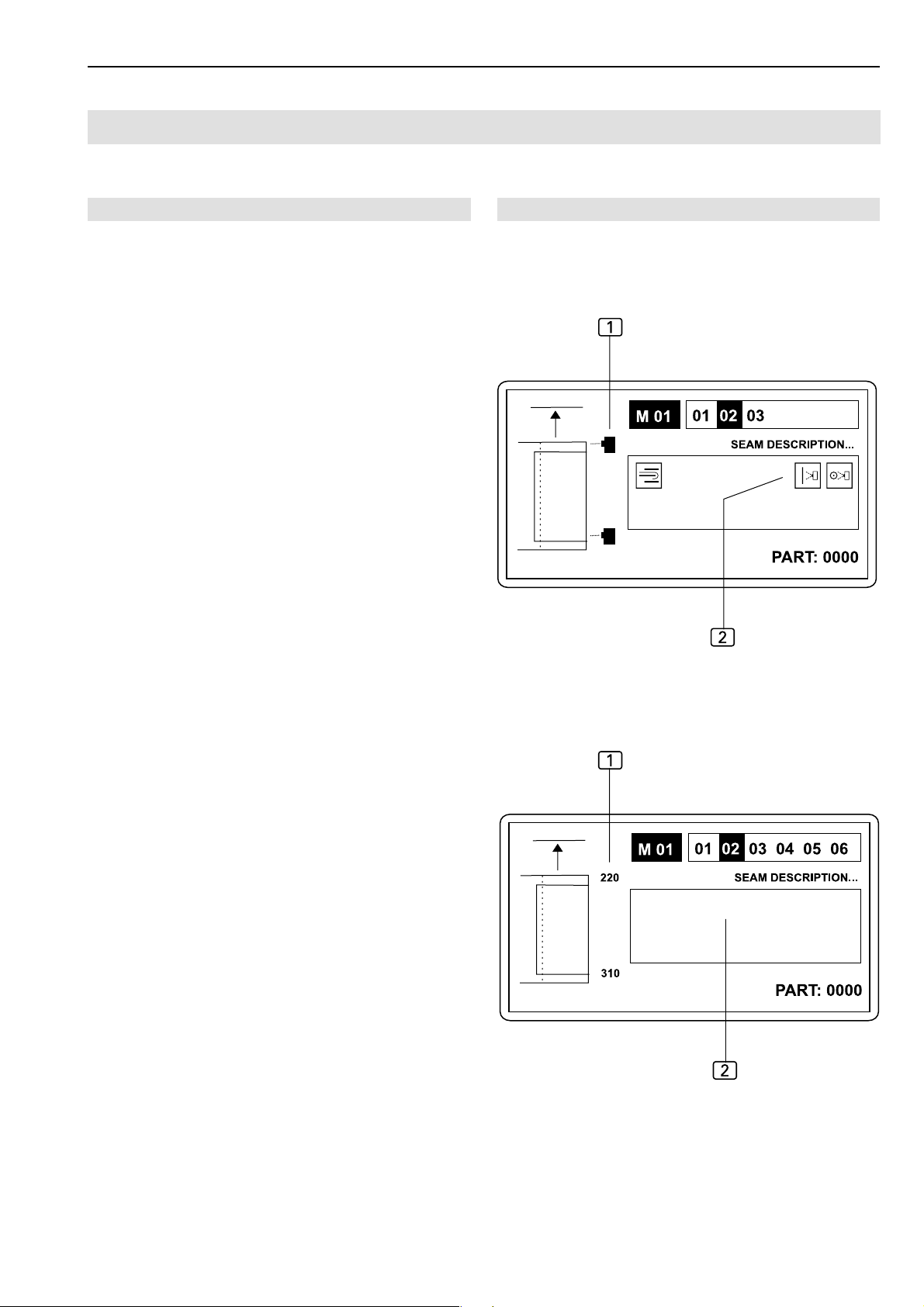
Short Seam Automat 2112-4 Working Instructions Beisler Automated Sewing Equipment
Programming
D.3
D.3.8 Level 2 special parameters / Functions
Functions of level 2 submenus
The following section describes the special parameters that
can be enabled or disabled as functions.
&+2?3A
F1 Back to start level
F2 Enable / disable functions
Enabling / disabling functions:
Functions can be enabled or disabled for a selected sewing program. This process covers three levels (3, 4 and
5). The changes made are reflected on the display:
Fig. 3: Enabled functions are displayed as symbols
and2.
Fig. 4: Disabled functions are removed from the sewing
pictograph1 and from the inner section 2 of the display.
1
Fig. 3/4
Fig. 3
Fig. 4
Start menu:
+
• Press key.
Level 3 is displayed.
- D 93 -
Page 94

Beisler Automated Sewing Equipment
Programming
D.3
D.3.9 Level 3 special parameters / Functions
Short Seam Automat 2112-4 Working Instructions
Level 3 submenus:
&>=F45:,
F1 Back to start level
F2 Switch photocell for beginning of seam on or off
F3 Switch photocell for end of seam on or off
F4 Switch folder on or off
F5 Sliding table
F8 Request next level (level 4)
Switching photocell for beginning of seam on or
off:
If the photocell that scans the start position of the seam
is switched off, the machine control requires a fixed insertion distance for machine operation. Therefore, switching
off the photocell results in a switch-over to a fixed insertion length (see Fig. 4). This function is directly related to
the photocell correction functions of the service menu.
>
Switching folder on or off:
The folder puts the pocket edge onto the pocket bag. If
this function is disabled, the pocket edge must be put onto
the pocket bag manually.
F
• Press key.
Switching sliding table on or off:
If this function is enabled, the pocket edge will not be stacked after end of the seam.
Transportation / sliding / lift table are out of function.
4
• Press key.
• Press key.
The alternating request of this function switches between
two modes:
Photocell for beginning of seam and fixed insertion distance.
Switching photocell for end of seam on or off:
If the photocell that scans the end position of the seam
is switched off, the machine control requires a fixed point
for the end of the seam to ensure correct machine operation. Therefore, switching off the photocell results in a
switch-over to a fixed end of seam point. This function is
directly related to the photocell correction functions of the
service menu.
=
• Press key.
The alternating request of this function switches between
two modes:
Photocell for end of seam and fixed end of seam point or
fixed seam length.
- D 94 -
Page 95

Short Seam Automat 2112-4 Working Instructions Beisler Automated Sewing Equipment
Programming
D.3
D.3.10 Level 4 special parameters / Functions
Level 4 submenus:
&D-GHI9,
F1 Back to level 3
F2 Enable/disable vacuum
F4 Enable/disable working plate rear cutter (left trou-
sers component)
F5 Enable/disable working plate front cutter (right trou-
sers component)
F6 Enable/disable pick-up plate front cutter (left slash
selvage)
F7 Sewing to fixed end-of-seam position
F8 Request next level (level 5)
Enabling or disabling vacuum
The vacuum is used as a fixing aid for the left or right trousers component before the clamp transport transfer. It can
be disabled during the checking of machine movements.
To enable or disable this function:
Enabling or disabling cutters
Both sewing programs for the left and right slash selvage (M01/ seam 12, 11) have been programmed at the factory with an individual cutter cut. For specific seams, this
function can be enabled or disabled separately:
1. Working plate rear cutter (left trousers component).
G
• Press key.
2. Working plate front cutter (right trousers component).
H
• Press key.
3. Pick-up plate cutter (left slash selvage).
I
• Press key.
D
• Press key.
NOTE - Operation without vacuum!
During normal production operation, the vacuum should
always be enabled as otherwise failures in the machine
cycle may occur.
Sewing to fixed end-of-seam position
If this function is enabled, a fixed position for the end of
the seam can be programmed for the sewing of the slash
selvages:
9
• Press key.
- D 95 -
Page 96

Beisler Automated Sewing Equipment
Programming
D.3
D.3.11 Level 5 special parameters / Functions
Short Seam Automat 2112-4 Working Instructions
Level 5 submenus
&<;8PM
F1 Back to level 4
F3 Switch top thread monitor on or off
F4 Switch rest thread monitor for lock stitch upper part
or bottom thread monitor for chain stitch upper part
on or off
F6 Clamp position after end of seam
F7 Clamp waiting position
F8 Scissors pick-up plate left side pocket
Switching the top thread monitor on or off:
For testing purposes, the top thread monitor can be switched off. To switch the top thread monitor on or off:
<
• Press key.
Switching clamp position behind end of seam on
or off:
If this function is enabled, the closed clamp moves to the
clamp transport end point behind the end of the seam before releasing the sewing piece. To enable or disable this
function:
8
• Press key.
Moving clamp to waiting position:
If this function is enabled, the clamp moves to the waiting
position (e. g. special parameter 05: 48 cm).
P
• Press key.
Scissors pick-up plate (left side pocket)
Enable scissors for left side pocket:
NOTE - Operation without top thread monitor!
During normal production, the top thread monitor should
always be switched on as otherwise the sewing programm
will not be stopped if the thread breaks.
Switching the rest thread monitor or bottom thread
monitor on or off:
Depending on the specifications of the sewing head, the
machine is equipped with either a rest thread monitor (for
lock stitch upper part) or a bottom thread monitor (for chain
stitch upper part). Both monitors can be switched on or
off for testing purposes. To switch a monitor on or off:
;
• Press key
NOTE - Operation without thread monitor!
During normal production, the rest thread monitor or the
top thread monitor should always be switched on as otherwise the sewing programm will not be stopped if the thread
breaks.
M
• Press key.
- D 96 -
Page 97

Short Seam Automat 2112-4 Working Instructions Beisler Automated Sewing Equipment
Programming
D.3
D.3.12 Level 2 special parameters / Lists
Parameter setting for level 2 submenus
The following section describes the special parameters that
are set in lists. When a submenu is requested, only those positions of the parameter list are displayed that refer
to the machine function. All other positions of the entire
parameter list can be browsed.
Browse through a list:
• Press 0 or / key.
Move to a line in the list:
• Press # or $ key.
Special parameter menu
&+2?3A
F1 Back to start level
F3 Select start modes, list
F4 Set upper part parameters, list
F5 Set stitch lengths and bar tacks, list
F6 Parameters for clamp transport, list
Selecting start modes:
Two modes can be set in this menu:
• Start mode,
• Blowing mode.
Confirm input:
• Press key.
Settable values:
Start mode
The selected start mode determines how the machine
operation is started and executed. Four modes are available:
• Mode 00,
• Mode 01,
• Mode 02,
• Mode 03,
• Mode 04,
• Mode 05,
• Mode 06,
• Mode 07,
The individual settings for machine operation are described
in Section B.3.10, Machine operation.
Blowing mode
When this mode is selected, the sewing piece is smoothened after the sewing process before it is transported
to the stacker.
• 00, off
• 01, on, only parts blowing Y47
• 02, on, only slash selvage blowing Y46
• 03, on, eingeschaltet parts blowing Y47 and slash
selvage blowing Y46
• Press 2 key.
Change parameters:
• Press % key.
• Insert new value using numeric keypad or
• Press 0 or / key.
- D 97 -
Page 98

Beisler Automated Sewing Equipment
Programming
D.3
D.3.12 Level 2 special parameters / Lists
Short Seam Automat 2112-4 Working Instructions
Setting upper part parameters:
This list is used for setting all parameters for functions of
the sewing head.
The minimum and maximum values of input are limited
by the program control unit. Values that are not within the
limits will not be accepted but reduced to the corresponding minimum or maximum value.
• Press ? key.
The parameter list is shown on the display.
NOTE - Sewing speed!
Possible settings for the sewing speed refer to the following sewing ranges:
• Sewing speed 1 to the start distance,
• sewing speed 2 to the center distance,
• sewing speed 3 to the end of the seam.
The speed is set in increments of 100 rpm.
Setting stitch lengths and bar tacks:
All settings for the configuration of the seam can be changed using this list.
The minimum and maximum values of input are limited
by the program control unit. Values that are not within the
limits will not be accepted but reduced to the corresponding minimum or maximum value.
Parameters for clamp transport:
This list is used to make all settings for the clamp movement.
• Press 8 key.
The parameter list shown on the display has the following
function:
01 Clamp insertion as seen from right end of rail
02 Stop position 600 mm is a safety value. Only values
higher than 600 mm can be input
03 Settable range: 35 % - 80 %
04 Settable range: 35 % - 99 %
05 Range of the curve where no sewing is performed. If
value "0" is input here, the sewing process starts im-
mediately.
• Press 3 key.
The parameter list is shown on the display.
- D 98 -
Page 99
Short Seam Automat 2112-4 Working Instructions Beisler Automated Sewing Equipment
Factory settings
D.4
D.4.1 Factory settings global parameters
M 01 global parameters 2112-4:
Pos.
01
02
03
04
05
06
07
10
11
12
13
14
17
18
20
21
22
23
24
25
26
27
28
32
33
35
36
37
38
39
40
Globalpara meter 2112-4
TILL CLAMP SIDEWAYS FWD
TILL CLAMP DOWN
TILL VACUUM OFF
THRD LE NGTH, BOBB IN F ULL
TILL CLAMP INSERTING
SEW ING END ->CL.SIDEW .
TIME AFTER CLAMP OPEN
TILL FOLDING CL. CLOSED
TILL FOLDER LIFT UP
TILL FOLDER SW INGS LEFT
IMP ULS FOLDER DOW N
CL.OPEN TILL FOLDER UP
TILL TE NS ION OP E N
DURATION OF TENS. OPE N
DUR.THREAD CLAMP FORW
TILL STACKER TRANSPORT
DUR.SLIDING TABLE OPEN
LIFT.TABLE MOD 00/01-99
DUR.LIFTING TABLE SINKS
TILL FABRIC CLAMP FORW.
TILL SCISSORS CLOSED
DURATION SCISSORS CUTS
TILL FABRIC CLAMP OPEN
BLOW OUT THE PART
CLAMP MOVES TO STACKER
THREAD CATCH. "UP " POS
SWITCH ON POS.OF TRIMM.
TRIMMING SPEED
DURATION OF TRIMMING
THREAD CATCH.TURNS BACK
PROCESS IN STEPS
Value Unit
0.1 sec
0.1 sec
0.1 sec
003 m
0.1 sec
0.1 sec
0.1 sec
0.5 sec
0.2 sec
0.2 sec
0.05 sec
0.20 sec
0.00 sec
0.4 sec
0.5 sec
0.1 sec
0.8 sec
0
0.99 sec
0.0 sec
0.0 sec
0.0 sec
0.0 sec
0.5 sec
0.0 sec
200 INC
100 INC
180 Upm
0.35 sec
00 INC
00
- D 99 -
Page 100
Beisler Automated Sewing Equipment
Factory settings
D.4
D.4.2 Factory settings special parameters
M 01 Special parameters 2112-4:
Pos. SEAM 01 - POCKET FACING Value Unit
01
02
03
04
05
06
07
08
09
10
12
13
14
16
17
18
19
24
25
26
27
30
32 BLOWING MODUS 00
CLAMP POSITION RIGHT
FOLDER SWING RELEASE
INSERT SPEED
CLAMP SPEED
WAITING POSITION
SEWING SPEED 1
SEWING SPEED 2
SEWING SPEED 3
DISTANCE SEWING SPEED 1
DISTANCE SEWING SPEED 3
THREA D MONITOR ON AFTE R
TOP THREAD MON. FILTER
BOTTOM THREAD MON. FILTER
TACKING LENGTH SEAM BEG
TACKING LENGTH SEAM END
STITCH LENGTH SEAM BEG
DISTANCE OF THIS ST.LEN
ST.LENGTH OF MAIN SEAM
STITCH LENGTH SEAM END
DIST.OF THIS ST.LENGTH
ST.LENGTH TRIMM.STITCH
START MODUS
030 mm
140 mm
80 %
99 %
43 cm
1200 Rpm
4200 Rpm
1200 Rpm
10 mm
15 mm
05 mm
20 mm
00
00 mm
00 mm
2.0 mm
08 mm
3.0 mm
2.0 mm
08 mm
1.5 mm
01
Short Seam Automat 2112-4 Working Instructions
- D 100 -
 Loading...