

Page 1

G
EtherCAT network adapter
GN-9386
User manual
-series GN-9386 EtherCAT Rev. 1.01.docx
Page 1 of (44)
Page 2

GN-9386 User Manual
G
DOCUMENT CHANGE SUMMARY
REV.
PAGES
REMARKS
DATE
Editor
1.00
New Document
2018/7/30
1.01
First release
2019/01/29
NJL
-series GN-9386 EtherCAT Rev. 1.01.docx
Page 2 of (44)
Page 3

GN-9386 User Manual
G
Contents
1. Important Notes ............................................................................................................................................................. 5
1.1. Safety Instruction .............................................................................................................................. 6
1.1.1. Symbols .............................................................................................................................................................. 6
1.1.2. Safety Notes ..................................................................................................................................................... 6
1.1.3. Certification ....................................................................................................................................................... 6
2. Environment Specification ........................................................................................................................................... 7
3. General Description ....................................................................................................................................................... 8
3.1. GN-9386 Specification ..................................................................................................................... 8
3.2. GN-9386 Wiring Diagram................................................................................................................. 9
3.3. GN-9386 LED Indicator .................................................................................................................. 10
3.3.1. LED Indicator .................................................................................................................................................. 10
3.3.2. MOD(Module Status LED) ........................................................................................................................ 10
3.3.3. RUN(Current Running Status LED) ....................................................................................................... 10
3.3.4. ERROR(Error State LED) ....................................................................................................................... 11
3.3.5. IOS LED(Extension Module Status LED) ....................................................................................... 11
3.3.6. Field Power, System Power LED(Field Power, System Power Status LED) ............... 11
3.3.7. Indicator states and flash rates .......................................................................................................... 12
3.4. GN-9386 Electrical Interface......................................................................................................... 13
3.4.1. RJ-45 Socket ................................................................................................................................................ 13
3.4.2. DIP Swit ch ..................................................................................................................................................... 13
3.4.3. RS232 Port for MODBUS/RTU, Touch Panel or I/O Guide .................................................... 14
3.5. EtherCAT ID Type Setup ............................................................................................................... 14
3.5.1. Hot Connection On TwinCAT .............................................................................................................. 14
3.6. I/O Process Image Map .................................................................................................................. 17
3.6.1. Example of Input Process Image (Input Register) Map ......................................................... 18
-series GN-9386 EtherCAT Rev. 1.01.docx
Page 3 of (44)
Page 4

GN-9386 User Manual
G
3.6.2. Example of Output Process Image (Output Register) Map ................................................. 19
4. Dimension ........................................................................................................................................................................ 21
4.1. GN-9386 ............................................................................................................................................. 21
5. EtherCAT Basics ............................................................................................................................................................. 22
5.1. EtherCAT Protocol .......................................................................................................................... 22
5.2. EtherCAT State Machine ............................................................................................................... 22
5.3. EtherCAT Mailbox ........................................................................................................................... 24
5.4. CoE Interface .................................................................................................................................... 26
5.4.1. Parameter management in the EtherCAT system .................................................................... 26
5.4.2. Communication Objects ........................................................................................................................ 27
6. MODBUS Interface ....................................................................................................................................................... 29
6.1. MODBUS Interface Register/Bit Map ......................................................................................... 29
6.2. Supported MODBUS Function Codes ....................................................................................... 30
6.2.1. 8 (0x08) Diagnostics ................................................................................................................................. 32
6.2.2. Error Response ........................................................................................................................................... 33
6.3. MODBUS Special Register Map .................................................................................................. 34
6.3.1. Adapter Identification Special Register (0x1000, 4096) ......................................................... 34
6.3.2. Adapter Information Special Register (0x1100, 4352) ............................................................ 35
6.3.3. Expansion Slot Information Special Resister (0x2000, 8192) ............................................ 36
6.4. Supported MODBUS Function Codes ....................................................................................... 38
7. TROUBLE SHOOTING .................................................................................................................................................. 39
APPENDIX A ....................................................................................................................................................................... 41
A.1. Product List ..................................................................................................................................... 41
A.2. Glossary............................................................................................................................................ 43
-series GN-9386 EtherCAT Rev. 1.01.docx
Page 4 of (44)
Page 5

GN-9386 User Manual
G
Warning!
Caution!
1. Important Notes
Solid state equipment has operational characteristics differing from those of electromechanical equipment.
Safety Guidelines for the Application, Installation and Maintenance of Solid State Controls describes some
important differences between solid state equipment and hard-wired electromechanical devices.
Because of this difference, and also because of the wide variety of uses for solid state equipment, all persons
responsible for applying this equipment must satisfy themselves that each intended application of this
equipment is acceptable.
In no event will CREVIS be responsible or liable for indirect or consequential damages resulting from the use
or application of this equipment.
The examples and diagrams in this manual are included solely for illustrative purposes. Because of the many
variables and requirements associated with any particular installation, CREVIS cannot assume responsibility
or liability for actual use based on the examples and diagrams.
If you don’t follow the directions, it could cause a personal injury, damage to the equipment or
explosion
Do not assemble the products and wire with power applied to the system. Else it may cause an electric
arc, which can result into unexpected and potentially dangerous action by field devices. Arching is
explosion risk in hazardous locations. Be sure that the area is non-hazardous or remove system power
appropriately before assembling or wiring the modules.
Do not touch any terminal blocks or IO modules when system is running. Else it may cause the unit to an
electric shock or malfunction.
Keep away from the strange metallic materials not related to the unit and wiring works should be
controlled by the electric expert engineer. Else it may cause the unit to a fire, electric shock or
malfunction.
If you disobey the instructions, there may be possibility of personal injury, damage to equipment
or explosion. Please follow below Instructions.
Check the rated voltage and terminal array before wiring. Avoid the circumstances over 55℃ of
temperature. Avoid placing it directly in the sunlight.
Avoid the place under circumstances over 85% of humidity.
Do not place Modules near by the inflammable material. Else it may cause a fire.
Do not permit any vibration approaching it directly.
Go through module specification carefully, ensure inputs, output connections are made with the
specifications. Use standard cables for wiring.
Use Product under pollution degree 2 environment.
-series GN-9386 EtherCAT Rev. 1.01.docx
Page 5 of (44)
Page 6

GN-9386 User Manual
G
1.1. Safety Instruction
1.1.1. Symbols
Identifies information about practices or circumstances that can cause an explosion
in a hazardous environment, which may lead to personal injury or death property
damage or economic loss.
Identifies information that is critical for successful application and understanding of
the product.
Identifies information about practices or circumstances that can lead to personal
injury, prop ert y dam age, or ec onomic loss.
Attentions help you to identity a hazard, avoid a hazard, and recognize
the consequences.
1.1.2. Safety Notes
The modules are equipped with electronic components that may be destroyed by
electrostatic discharge. When handling the modules, ensure that the environment
(persons, workplace and packing) is well grounded. Avoid touching conductive
components, e.g. G-BUS Pin.
1.1.3. Certification
c-UL-us UL Listed Industrial Control Equipment, certified for U.S. and Canada
See UL File E235505
FCC, Reach, RoHS- II, China RoHS
CE Certificate
EN 61000-6-2; Industrial Immunity
EN 61000-6-4; Industrial Emissions
-series GN-9386 EtherCAT Rev. 1.01.docx
Page 6 of (44)
Page 7

GN-9386 User Manual
G
Environment Specification
Operating Te mperature
-40℃~70℃
UL Temperature
-20℃~60℃
Storage Temperature
-40℃~85℃
Relative Humidity
5% ~ 90% non-condensing
Mounting
DIN rail
General Specification
Shock Operating
IEC 60068-2-27
Vibration resistance
Sine Vibration (Based on IEC 60068-2-6)
- Test time : 1hrs for each test
EMC resistance burst/ESD
EN 61000-6-2 : 2005
EN 61000-6-4/ALL : 2011
Installation Pos. / Protect. Class
Variable/IP20
Product Certifications
CE, UL
2. Environment Specificati o n
- 5 ~ 25Hz : ±1.6mm
- 25 ~ 300Hz : 4g
- Sweep Rate : 1 Oct/min, 20 Sweeps
Random Vibration (Based on IEC 60068-2-64)
- 10 ~ 40 Hz : 0.0125 g
- 40 ~ 100 Hz : 0.0125 → 0.002 g
- 100 ~ 500 Hz : 0.002 g
- 500 ~ 2000 Hz : 0.002 → 1.3 x 10
2
/Hz
2
/Hz
2
/Hz
-4g2
/Hz
-series GN-9386 EtherCAT Rev. 1.01.docx
Page 7 of (44)
Page 8

GN-9386 User Manual
G
3. General Description
3.1. GN-9386 Specification
Items Specification
Communication Interface Specification
Adapter Type Slave Node (EtherCAT)
Max. Expansion Slot 63 slots
I/O Data Size Max 128 bytes each slot
Max. Network Node 65535
Baud Rate 100Mbps
Bus Connection 2 x RJ-45
Mac Address / IP Address Not needed
Other Serial Port RS232 for MODBUS/RTU, Touch Panel or I/O Guide(Crevis Soft ware)
Node : 1 (Fixed)
Serial Configuration
(RS232)
Baud Rate : 115200 (Fixed)
Data bit : 8 (Fixed)
Parity bit : No parity (Fixed)
Stop bit : 1 (Fixed)
6 Status LEDs
1 Green/Red, Module Status (MOD)
Indicator
Module Location Starter module left side of G-Series system
Field Power Detection About 14Vdc
General Specification
System Power
Power Dissipation 70mA @ 24Vdc
Current for I/O Module 1.5A @ 5Vdc
Isolation
Field Power
1 Green, Network Status (RUN)
1 Red, Error Status (ERROR)
1 Green/Red Expansion I/O Module Statsus (IOS)
1 Green, System Power Status
1 Green, Field Power Status
Supply voltage : 24Vdc nominal
Supply voltage range : 15~32Vdc
Protection : Output current limit (Min. 1.5A)
Reverse polarity protection
System power to internal logic : Non-Isolation
System power I/O driver : Isolation
Supply voltage : 24Vdc typical (Max. 32Vdc)
* Field Power Range is different depending on IO Module series.
Refer to IO Module`s Specification.
Weight 167g
Module Size 54mm x 99mm x 70mm
-series GN-9386 EtherCAT Rev. 1.01.docx
Page 8 of (44)
Page 9

GN-9386 User Manual
G
3.2. GN-9386 Wiring Diagram
Pin No. Signal Description Signal Description Pin No.
0 System Power, 24V System Power, Ground 1
2 System Power, 24V System Power, Ground 3
4 F.G F.G 5
6 Field Power, Ground Field Power, Ground 7
8 Field Power, 24V Field Power, 24V 9
-series GN-9386 EtherCAT Rev. 1.01.docx
Page 9 of (44)
Page 10
GN-9386 User Manual
G
Status
LED
Not Powered
OFF
Normal, Operational
Green
Device in Standby
Flashing Green
Minor Fault
Flashing Red
Unrecoverable Fault
Red
Status
LED To ind icate
Init OFF State of the EtherCAT State Machine: INIT = Initialization.
Pre
Blinking
State of the EtherCAT State Machine: PREOP =
Safe
Single Flash
State of the EtherCAT State Machine: SAFEOP = Safe
Initialization or Bootstrap
Flashes
State of the EtherCAT State Machine: BOOT = Bootstrap (Update
of the coupler firmware)
Operational
ON State of
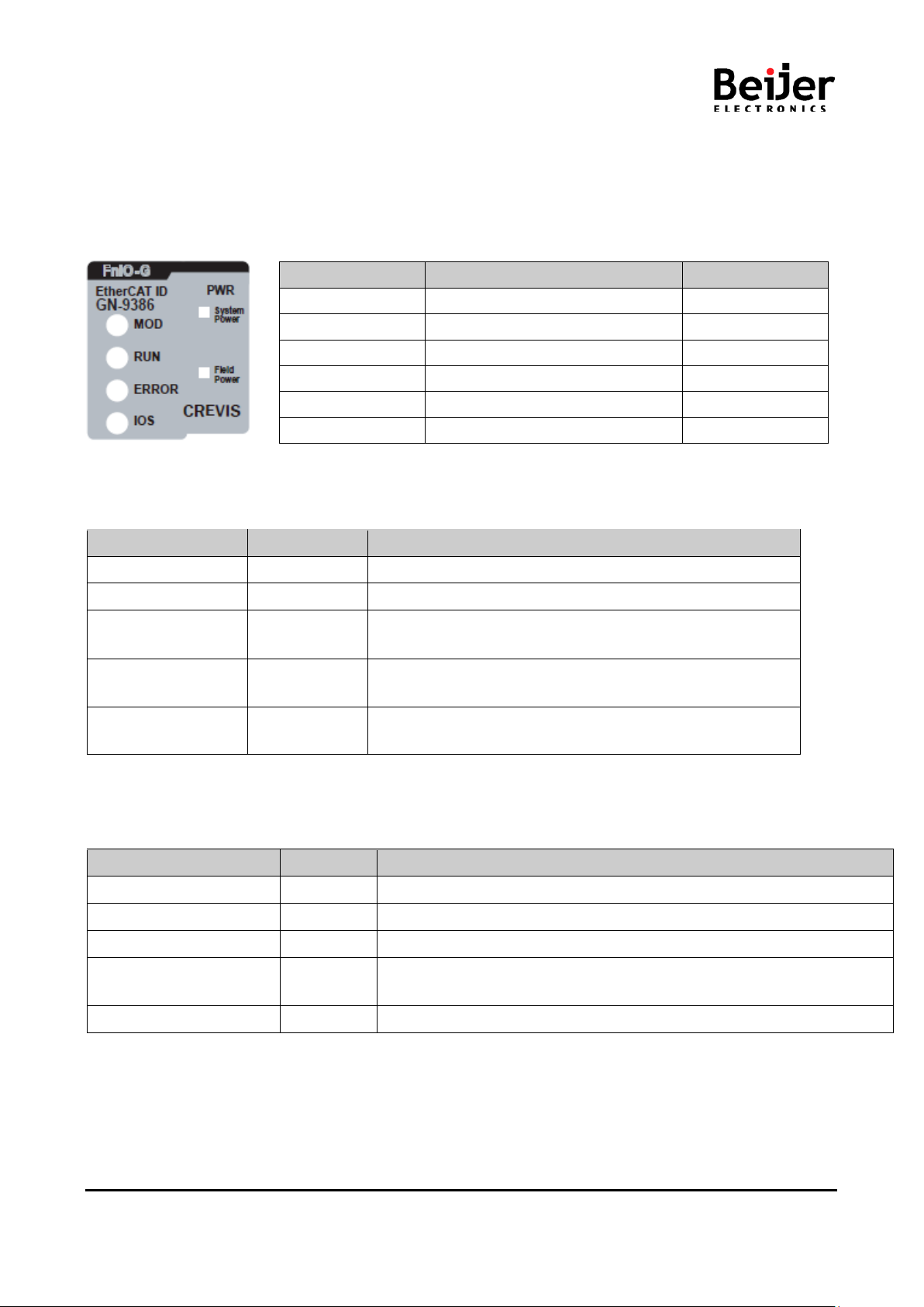
3.3. GN-9386 LED Indicator
3.3.1. LED Indicator
LED No. LED Function / Description LED Color
MOD Module Status Green/Red
RUN Current Running Status Green
ERROR Error Status (EtherCAT) Red
IOS Extension Module Status Green/Red
System Power System Power Enable Green
Field Power Field Power Enable Green
3.3.2. MOD(Module Status LED)
To indicate
power is not supplied to the unit.
The unit is operating in normal condition.
The EEPROM parameter is not initialized yet.
Serial Number is zero value (0x00000000)
The unit has occurred recoverable fault in self-testing.
- EEPROM checksum fault.
The unit has occurred unrecoverable fault in self-testing.
- Firmware fault
3.3.3. RUN(Current Running Status LED)
-Operation
-Operation
the EtherCAT State Machine: Operational.
Pre-Operation.
-Operation.
-series GN-9386 EtherCAT Rev. 1.01.docx
Page 10 of (44)
Page 11

GN-9386 User Manual
G
Status
LED
To indicate
3.3.4. ERROR(Error State LED)
No Error OFF No Error.
Invalid Configuration Blinking Invalid Configuration.
3.3.5. IOS LED(Extension Module Status LED)
Status LED To indicate
Not Powered OFF Device has no expansion module or may not be powered.
Internal Bus On-line,
Do not Exchanging I/O
Internal Bus Connection,
Run Exchanging I/O
Internal Bus Connection Fault
during Exchanging I/O
Expansion Configuration
Failed
Flashing
Green
Green Exchanging I/O data.
Red
Flashing
Red
Internal Bus is normal but does not exchanging I/O data.
(Passed the expansion module configuration)
One or more expansion module occurred in fault state.
- Changed expansion module configuration.
- Internal Bus communication failure.
- Mismatch vendor code be tw een ad apter and expansion module.
Failed to initialize expansion module.
- Detect invalid expansion module ID.
- Overflow Input/Output size.
- No expansion module.
- Too many expansion module.
- Initial protocol failure.
3.3.6. Field Power, System Power LED(Field Power, System Power Status LED)
Status LED To indicate
Not supplied field, system power OFF Not supplied 24Vdc field power, 5Vdc system power.
Supplied field, system power Green Supplied 24Vdc field power, 5Vdc system power.
-series GN-9386 EtherCAT Rev. 1.01.docx
Page 11 of (44)
Page 12

GN-9386 User Manual
G
LED ON
Constantly ON
3.3.7. Indicator states and flash rates
LED OFF Constantly OFF.
LED flickering
LED blinking
LED single flash
LED double flash
LED triple flash
Equal ON and OFF times with a frequency of approximately 10 Hz: ON for approximately
50ms and OFF for approximately 50ms.
Equal ON and OFF times with a frequency of approximately 2, 5Hz: ON for approximately
200ms followed by OFF for approximately 200ms.
One short flash (approximately 200ms) followed by a long OFF phase
(approximately 1000ms)
A sequence of two short flashes (approximately 200ms), separated by an OFF phase
(approximately 200ms).
The sequence is finished by a long OFF phase (approximately 1000ms)
A sequence of three short flashes (approximately 200ms), separated by an OFF phase
(approximately 200ms).
The sequence is finished by a long OFF phase (approximately 1000ms)
-series GN-9386 EtherCAT Rev. 1.01.docx
Page 12 of (44)
Page 13
GN-9386 User Manual
G
3.4. GN-9386 Electrical Interface
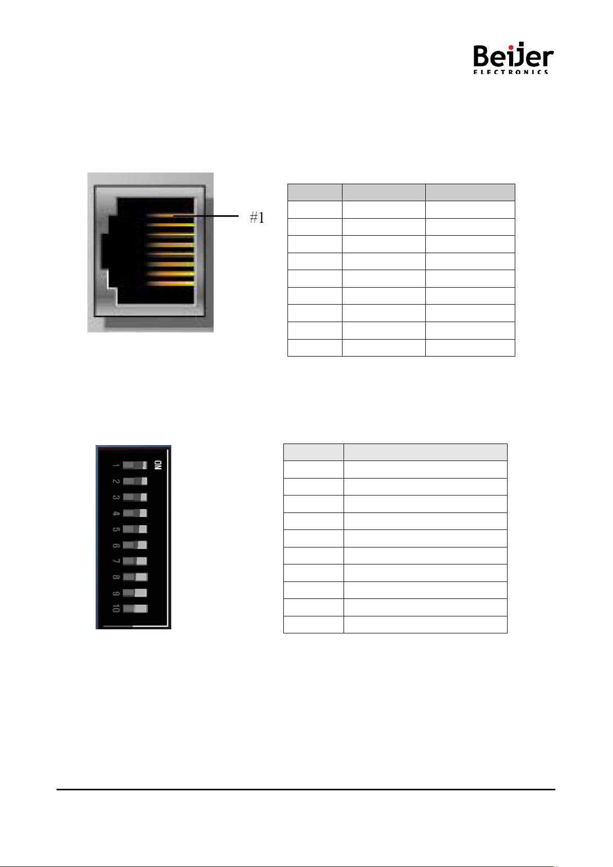
3.4.1. RJ-45 Socket
RJ-45 Signal Name Description
1 TD+ Transmit +
2 TD- Transmit 3 RD+ Receive +
4 -
5 -
6 RD- Receive 7 -
8 -
Case Shield
Shielded RJ-45 Socket
3.4.2. DIP Switch
DIP Pole# Description
1 IdentificationValue DIP bit#0
2 IdentificationValue DIP bit#1
3 IdentificationValue DIP bit#2
4 IdentificationValue DIP bit#3
5 IdentificationValue DIP bit#4
6 IdentificationValue DIP bit#5
7 IdentificationValue DIP bit#6
8 IdentificationValue DIP bit#7
9 Not Used
10 Not Used
-series GN-9386 EtherCAT Rev. 1.01.docx
Page 13 of (44)
Page 14

GN-9386 User Manual
G
3.4.3. RS232 Port for MODBUS/RTU, Touch Panel or I/O Guide
Pin# Signal Name Description
1 Reserved ---2 TXD RS232 TXD
3 RXD RS232 RXD
4 GND RS232 GND
3.5. EtherCAT ID Type Setup
3.5.1. Hot Connection On TwinCAT
Hot connection function c an be used to remove a node from a preconf igured Configuration or change the
location of nodes and flexible.This featur e is avai labl e only Ethercat ID Type in TwinCAT.
The user can use the external Dip Switch settings of the Adapter Identification Value.
For an example of using an external Dip Switch ( Refer to 2.4.2. )
Ex) node 1 (Min)
Ex) node 255 (Max)
-series GN-9386 EtherCAT Rev. 1.01.docx
Page 14 of (44)
Page 15

GN-9386 User Manual
G
Hot Connection setting procedure
1. Add the EtherCAT ID Type in TwinCAT.
2. Hot Connect Group settings
Set the identification value same as dip-switch.
-series GN-9386 EtherCAT Rev. 1.01.docx
Page 15 of (44)
Page 16

GN-9386 User Manual
G
3. Hot connection group set up is completed, run the Reload I/O device(F4).
4. Now you can use the Hot connection feature.
Node is not overlapped between products. If there are same nodes, It should be changed.
-series GN-9386 EtherCAT Rev. 1.01.docx
Page 16 of (44)
Page 17

GN-9386 User Manual
G
3.6. I/O Process Image Map
An expansion module may have 3 types of data as I/O data, configuration parameter and memory register.
The data exchange bet wee n network adapter and ex pansio n modules is done vi a an I/O pr oces s image data
by G-Series protocol. T he following figure shows the data flow of process image between n etwork adapter
and expansion modules.
-series GN-9386 EtherCAT Rev. 1.01.docx
Page 17 of (44)
Page 18

GN-9386 User Manual
G
3.6.1. Example of Input Process Image (Input Register) Map
Input image data depends on slot position and expansion sl ot data type. Input process im age data is only
ordered by expansion slot position.
For example slot configuration
Slot Address Module Description
#0 EtherCAT Adapter
#1 8-discrete input
#2 8-discrete input
#3 4-analog input
#4 8-discrete input
#5 8-discrete input
#6 8-discrete input
#7 16-discrete input
#8 8-discrete input
• Input Process Image
TXPDO Entries Byte Bit 7 Bit 6 Bti 5 Bit 4 Bit 3 Bit 2 Bit 1 Bit 0
0x1A01 0x6010 0 Discrete Input 8 pts (Slot#1)
0x1A02 0x6020 1 Discrete Input 8 pts (Slot#2)
2 Analog Input Ch0 low byte (Slot#3)
3 Analog Input Ch0 high byte (Slot#3)
4 Analog Input Ch1 low byte (Slot#3)
0x1A03 0x6030
0x1A04 0x6040 10 Discrete Input 8 pts (Slot#4)
0x1A05 0x6050 11 Discrete Input 8 pts (Slot#5)
0x1A06 0x6060 12 Discrete Input 8 pts (Slot#6)
0x1A07 0x6070
0x1A08 0x6080 15 Discrete Input 8 pts (Slot#8)
5 Analog Input Ch1 high byte (Slot#3)
6 Analog Input Ch2 low byte (Slot#3)
7 Analog Input Ch2 high byte (Slot#3)
8 Analog Input Ch3 low byte (Slot#3)
9 Analog Input Ch3 high byte (Slot#3)
13 Discrete Input 8 pts (Slot#7)
14 Discrete Input 8 pts (Slot#7)
-series GN-9386 EtherCAT Rev. 1.01.docx
Page 18 of (44)
Page 19

GN-9386 User Manual
G
3.6.2. Example of Output Process Image (Output Register) Map
Output image data de pen d s on s lot pos i tio n and ex pans ion s lot d ata t ype. O utp ut pr oc ess image data is only
ordered by expansion slot position.
For example slot configuration
Slot Address Module Description
• Output Pr o cess Image
RXPDO Entries Byte Bit 7 Bit 6 Bit 5 Bit 4 Bit 3 Bit 2 Bit 1 Bit 0
0x1601 0x7010 0 Discrete Output 8 pts (Slot#1)
0x1602 0x7020 1 Discrete Output 8 pts (Slot#2)
2
3 Analog Output Ch0 high byte (Slot#3)
4 Analog Output Ch1 low byte (Slot#3)
5 Analog Output Ch1 high byte (Slot#3)
0x1603 0x7030
6 Analog Output Ch2 low byte (Slot#3)
7 Analog Output Ch2 high byte (Slot#3)
8 Analog Output Ch3 low byte (Slot#3)
9 Analog Output Ch3 high byte (Slot#3)
0x1604 0x7040 10 Discrete Output low 4 pts (Slot#4)
0x1605 0x7050 12 Discrete Output low 4 pts (Slot#5)
0x1606 0x7060 13 Discrete Output low 8 pts (Slot#6)
0x1607 0x7070 14 Discrete Output low 8 pts (Slot#7)
Analog Output Ch0 low byte (Slot#3)
#0 EtherCAT Adapter
#1 8-discrete output
#2 8-discrete output
#3 4-analog output
#4 4- relay output
#5 4-relay output
#6 8-discrete output
#7 8-discrete output
#8 4-analog output
#9 4-relay output
#10 16-discrete output
-series GN-9386 EtherCAT Rev. 1.01.docx
Page 19 of (44)
Page 20

GN-9386 User Manual
G
15 Analog Output Ch0 low byte (Slot#8)
16 Analog Output Ch0 high byte (Slot#8)
17 Analog Output Ch1 low byte (Slot#8)
0x1608 0x7080
0x1609 0x7090 24 Discrete Output low 8 pts (Slot#9)
0x160A 0x70A0
18 Analog Output Ch1 high byte (Slot#8)
19 Analog Output Ch2 low byte (Slot#8)
20 Analog Output Ch2 high byte (Slot#8)
21 Analog Output Ch3 low byte (Slot#8)
22 Analog Output Ch3 high byte (Slot#8)
25 Discrete Output low 8 pts (Slot#10)
26 Discrete Output high 8 pts (Slot#10)
-series GN-9386 EtherCAT Rev. 1.01.docx
Page 20 of (44)
Page 21

GN-9386 User Manual
G
4. Dimension
4.1. GN-9386
(mm)
-series GN-9386 EtherCAT Rev. 1.01.docx
Page 21 of (44)
Page 22

GN-9386 User Manual
G
5. EtherCAT Basics
The EtherCAT protocol uses an officially assigned EtherType inside the Ethernet Frame. The use of this
EtherType allows transport of control data directly within the Ethernet frame without redefining the standard
Ethernet frame. The frame may consist of several sub-telegrams, each serving a particular memory area of
the logical process images that can be up to 4 gigabytes in size. Addressing of the Ethernet terminals can be
in any order because the data sequence is independent of the physical order. Broadcast, Multi-cast and
communication between slaves are possible.
5.1. EtherCAT Protocol
The EtherCAT protocol uses an officially assigned EtherType inside the Ethernet Frame. The use of this
EtherType allows transport of control data direc tly within the Ethernet f rame without redef ining the standard
Ethernet frame. T he frame m ay consist of se veral sub-telegram s, each serving a particular m emory area of
the logical process im ages that c an b e up t o 4 g iga b yt es in si ze. A ddres s in g of th e Eth er net t erminals can be
in any order because the data sequence is independent of the physical order. Broadcast, Multicast and
communication between slaves are possible.
5.2. EtherCAT State Machine
The state of the EtherCAT slave is controlled vi a the EtherCAT State Machine (ESM). Depen ding upon the
state, different functions are accessible or executable in the EtherCAT slave. Specific commands must be
sent by the EtherCAT master to the device in each state, particularly during the boot up of the slave.
A distinction is made between the following states:
• Init
• Pre-Operational
• Safe-Operational and
• Operational
• Bootstrap
The regular state of each EtherCAT slave after bootup is the OP state.
-series GN-9386 EtherCAT Rev. 1.01.docx
Page 22 of (44)
Page 23

GN-9386 User Manual
G
Init
After switch-on the EtherCAT slave in the Init state. No mailbox or process data communication is possible.
The EtherCAT master initializes sync manager channels 0 and 1 for mailbox communication.
Pre-Operational (Pre-Op)
During the transition between Init and Pre-Op the EtherCAT slave checks whether the mailbox was initialized
correctly.
In Pre-Op state mailbox communication is possible, but not process data communication. The EtherCAT
master initializes the sync manager channels for process data (from sync manager channel 2), the FMMU
channels and, if the slave supports configurable mapping, PDO mapping or the sync manager PDO
assignment. In this state the settings for the process data transfer and perhaps terminal-specific parameters
that may differ from the default settings are also transferred.
Safe-Operational (Safe-Op)
During transition between Pre-Op and Safe-Op the EtherCAT slave checks whether the sync manager
channels for process data communication and, if required, the distributed clocks settings are correct. Before it
acknowledges the change of state, the EtherCAT slave copies current input data into the associated DP-RAM
areas of the EtherCAT slave controller (ECSC).
In Safe-Op state mailbox and process data communication is possible, although the slave keeps its outputs in
a safe state, while the input data are updated cyclically.
Operational (Op)
Before the EtherCAT master switches the EtherCAT slave from Safe-Op to Op it must transfer valid output
data.
In the Op state the slave copies the output data of the masters to its outputs. Process data and mailbox
communication is possible.
Bootstrap
In the Boot state the slave firmware can be updated. The Boot state can only be reached via the Init state.
In the Boot state mailbox communication via the file access over EtherCAT (FoE) protocol is possible, but no
other mailbox communication and no process data communication.
-series GN-9386 EtherCAT Rev. 1.01.docx
Page 23 of (44)
Page 24

GN-9386 User Manual
G
5.3. EtherCAT Mailbox
The device profiles describe the application parameters and the functional behavior of the devices including
the device class-specific state machines. For many device classes, fieldbus technology already offers reliable
device profiles, for example for I/O devices, drives or valves. Users are familiar with these profiles and the
associated parameters and tools. No EtherCAT-specific device profiles have therefore been developed for
these device classes. Instead, simple interfaces for existing device profiles are being offered (see Fig. 1).
This greatly assists users and device manufacturers alike during the migration from the existing fieldbus to
EtherCAT. At the same time the EtherCAT specification keeps it simple because all the protocols are optional.
The device manufacturer only has to implement the protocol that the device application needs.
<Fig. 1> Several Device Profiles and Protocols can co-exist side by side
CAN application layer over EtherCAT (CoE)
CANopen® device and application profiles are available for a wide range of device classes and applications,
ranging from I/O components, drives, encoders, proportional valves and hydraulic controllers to application
profiles for plastic or textile machinery, for example. EtherCAT can provide the same communication
mechanisms as the familiar CANopen [1] mechanisms: object dictionary, PDO (process data objects) and
SDO (service data objects) – even the network management is comparable. EtherCAT can thus be
implemented with minimum effort on devices equipped with CANopen. Large parts of the CANopen firmware
can be reused. Objects can optionally be expanded in order to account for the larger bandwidth offered by
EtherCAT.
-series GN-9386 EtherCAT Rev. 1.01.docx
Page 24 of (44)
Page 25

GN-9386 User Manual
G
Servo drive profile according to IEC 61800-7-204(SERCOS) (SoE)
SERCOS interfac e™ is acknowledged as a high-performance real-time communication interface, particularly
for motion control applications. The SERCOS profile for servo drives and the communication technology are
covered by the IEC 61800-7-204 standard. The mapping of this profile to EtherCAT (SoE) is specified in part
304 [2]. The service channel, and therefore access to all parameters and functions residing in the drive, is
based on the EtherCAT mailbox.
Here too, the focus is on compatibility with the existing protocol (access to value, attribute, name, units, etc.
of the IDNs) and expandability with regard to data length limitation. The process data, with SERCOS in the
form of AT and MDT data, are transferred using EtherCAT device protocol mechanisms. The mapping is
similar to the SERCOS mapping. The EtherCAT slave state machine can also be mapped easily to the
phases of the SERCOS protocol. EtherCAT provides advanced real-time Ethernet technology for this device
profile, which is particularly widespread in CNC applications. Optionally, the command position, speed or
torque can be transferred. Depending on the implementation, it is even possible to continue using the same
configuration tools for the drives.
Ethernet over EtherCAT (EoE)
The EtherCAT technology is not only fully Ethernet-compatible, but also characterized by particular openness
“by design”: the protocol tolerates other Ethernet-based services and protocols on the same physical network
– usually even with minimum loss of performance. There is no restriction on the type of Ethernet device that
can be connected within the EtherCAT segment via a switchport.
The Ethernet frames are tunneled via the EtherCAT protocol, which is the standard approach for internet
applications(e.g. VPN, PPPoE (DSL), etc.). The EtherCAT network is fully transparent for the Ethernet device,
and the real-time characteristics are not impaired (see Fig. 2).
The master acts like a layer 2 switch that redirects the frames to the respective devices according to the
address
information. All internet technologies can therefore also be used in the EtherCAT environment: integrated web
server, e-mail, FTP transfer, etc.
<Fig. 2> Transparent for all Ethernet Protocols
-series GN-9386 EtherCAT Rev. 1.01.docx
Page 25 of (44)
Page 26

GN-9386 User Manual
G
File Access over EtherCAT (FoE)
any data structure in the device. Standardized firmware upload to devices is therefore possible, irrespective of
whether or not they support TCP/IP.
Literature
[1] EN 50325-4: Industrial communications subsystem based on ISO 11898 (CAN) for controller-device
interfaces. Part 4: CANopen.
[2] IEC 61800-7-301/304, Adjustable speed electrical power drive systems – Par t 7-301: Generic interface
and use
of profiles for power drive systems – Mapping of profile type 1 to network technologies – Part 7-304: Generic
interface and use of profiles for power drive systems – Mapping of profile type 4 to network technologies
5.4. CoE Interface
5.4.1. Parameter management in the EtherCAT system
The CiA organization (CAN in Automation) pursues among other things the goal of creating order and
exchange abilit y between devices of the same type by the standardizati on of device descriptions. For this
purpose so-called profiles are defined, which conclusively describe the changeable and unchangeable
parameters of a device. Such a parameter encompasses at least the following characteristics:
• Index number – for the unambiguous identification of all parameters. The index number is divided into
a main index and a subindex in order to mark and arrange associated parameters.
- Main index
- Subindex, offset by a colon ‘:’
• Official name – in the form of an understandable, self-descriptive text
• Specification of changeability, e.g. whether it can only be read or can also be written
• A v alue – depending upon t he parameter the value can be a text, a number or another parameter
index.
Index Range
The relevant ranges for EtherCAT fieldbus users are:
x1000 : This is where fixed identity information for the device is stored, including name, manufacturer,
serial number etc., plus information about the current and available process data configurations.
x8000 : T his is where the operational and funct ional parameters for all channels ar e stored, such as filter
settings
or output frequency.
Other important ranges are:
x4000 : In some EtherC AT devices the channe l parameters are stored her e (as an alternative to the x8000
range).
x6000 : Input PDOs ("input" from the perspective of the EtherCAT master)
x7000 : Output PDOs ("output" from the perspective of the EtherCAT master)
-series GN-9386 EtherCAT Rev. 1.01.docx
Page 26 of (44)
Page 27

GN-9386 User Manual
G
1018
10F1
1601*
1A01*
1C00
1C12
1C13
5.4.2. Communication Objects
Index Sub-index Name Flags Default value
1000 Device type RO 0x00001389
1001 Gbus Status RO Normal Operation : 0x00 **
1002 Master Fault Aaction RW 0x00
1008 Device name RO GN-9386(Crevis)
1009 Hardware version RO GN-9386.v1
100A Software version RO 1.000
Identity RO 0x05
01 Vendor ID (Crevis: 029D) RO 0x0000029D
02 Product code RO 0x4E419386
03 Revision RO 0x0001000
04* Serial number RO 0xFFFFFFFF
05 Release date RO 0x20160823
Error Settings RO 0x02
01 Local Error Reaction RO 0x00000000
02 Sync Error Counter Limit RO 0x00000004
Slot#x, GT--xxxx,RXPDO RO 0xnn
01 SubI ndex 001 RO 0x7010:01, 8
... ... ... ...
nn SubI ndex nnn RO 0x7010:nn, 8
Slot#x, GT-xxxx,TXPDO RO 0xnn
01 SubI ndex 001 RO 0x6010:01, 8
... ... ... ...
nn SubI ndex nnn RO 0x6010:nn, 8
Sync manager type RO 0x04
01 SubIndex 001 RO 0x01
02 SubI ndex 002 RO 0x02
03 SubI ndex 003 RO 0x03
04 SubI ndex 004 RO 0x04
RxPDO assign RO 0x01
01 SubI ndex 001 RO 0x1601
TxPDO assign RO 0x02
01 SubI ndex 001 RO 0x1A01
02 SubI ndex 002 RO 0x1A02
-series GN-9386 EtherCAT Rev. 1.01.docx
Page 27 of (44)
Page 28

GN-9386 User Manual
G
7010*
8000
8nn0*
F000
F010*
F050
GT-xxxx RO 0xnn
01 Byte#0 RW P 0x00
... ... ... ...
nn Byte#nnn RW P 0x00
GN-9386(Parameter) RO
01 Byte#0 RW
02 Byte#1 RW
03 Byte#2 RW
04 Byte#3 RW
GT-xxxx(Parameter) RO
01 Byte#0 RW
... ... ... ...
nn Byte#nnn RW
Module device profile RO
01 Module index distance RO
02 Maximum numver of modules RO
Module List RO
01 Subindex 001 (GN-9386) RO 0x00009386
... ... ... ...
63 Subindex 063 RO 0x0000xxxx
Detected Module Ident List RO
01... SubIndex 001 RO
*This value can be changed depending on the configuration of expansion modules
** G-BUS Status
- Normal Operation : 0x00
- Communication Fault : 0x02
- Configuration Failed : 0x03
- No Expansion Module : 0x04
- Vendor Error : 0x07
- Not expected slot : 0x08
- CRC Error : 0x09
-series GN-9386 EtherCAT Rev. 1.01.docx
Page 28 of (44)
Page 29

GN-9386 User Manual
G
6. MODBUS Interface
6.1. MODBUS Interface Register/Bit Map
• Register Map
Start Address Read/Write Description Func. Code
0x0000 ~ Read Process input image registers (Real Input Register) 3,4,23
0x0800 ~ Read/Write Process output image registers (Real Output Register) 3,16,23
0x1000 * Read A dapter Identification special registers. 3,4,23
0x1020 * Read/Write Adapter Watchdog, other time special register. 3,4,6,16,23
0x1100 * Read/Write Adapter Information special registers. 3,4,6,16,23
0x2000 * Read/Write Expansion Slot Information special registers. 3,4,6,16,23
* The special register map must be accessed by read/write of every each address (one address).
• Register Map
Start Address Read/Write Description Func. Code
0x0000~ Read
0x1000~ Read/Write
Process input image bits
All input registers area are addressable by bit address.
Size of input image bit is size of input image register * 16.
Process output image bits
All output registers area are addressable by bit address.
Size of output image bit is size of output image register * 16.
2
1,5,15
-series GN-9386 EtherCAT Rev. 1.01.docx
Page 29 of (44)
Page 30

GN-9386 User Manual
G
6.2. Supported MODBUS Function Codes
Function
Code
1(0x01)
2(0x02)
Function Description
This function code is used to read from 1 to 2000 contiguous
status of coils in a remote device. The Request PDU specifies the
Read Coils
(Read output bit)
Read Discrete Inputs
(Read input bit)
starting address, i.e. the address of the first coil specified, and the
number of coils. In the PDU Coils are addressed starting at zero.
Therefore coils numbered 1-16 are addressed as 0-15. The coils
in the response message are packed as one coil per bit of the
data field. Status is indicated as 1= ON and 0= OFF.
This function code is used to read from 1 to 2000 contiguous
status of discrete inputs in a remote device. The Request PDU
specifies the starting address, i.e. the address of the first input
specified, and the number of inputs. In the PDU Discrete Inputs
are addressed starting at zero. Therefore Discrete inputs
numbered 1-16 are addressed as 0-15.
The discrete inputs in the response message are packed as one
input per bit of the data field.
Status is indicated as 1= ON; 0= OFF.
3(0x03)
4(0x04)
5(0x05)
6(0x06)
Read Holding Registers
(Read output word)
Read Input Registers
(Read input word)
Write Single Coil
(Write one bit output)
Write Single Register
(Write one word output)
This function code is used to read the contents of a contiguous
block of holding registers in a remote device. The Request PDU
specifies the starting register address and the number of
registers. The register data in the response message are packed
as two bytes per register, with the binary contents right justified
within each byte. For each register, the first byte contains the high
order bits and the second contains the low order bits.
This function code is used to read from 1 to approx. 125
contiguous input registers in a remote device. The Request PDU
specifies the starting register address and the number of
registers. The register data in the response message are packed
as two bytes per register, with the binary contents right justified
within each byte. For each register, the first byte contains the high
order bits and the second contains the low order bits.
This function code is used to write a single output to either ON or
OFF in a remote device. The requested ON/OFF state is specified
by a constant in the request data field. A value of FF 00 hex
requests the output to be ON. A value of 00 00 requests it to be
OFF. All other values are illegal and will not affect the output.
This function code is used to write a single holding register in a
remote device. Therefore register numbered 1 is addressed as 0.
The normal response is an echo of the request, returned after the
register contents have been written.
-series GN-9386 EtherCAT Rev. 1.01.docx
Page 30 of (44)
Page 31

GN-9386 User Manual
G
Diagnostics
8(0x08)
15(0x0F)
16(0x10)
(Read diagnostic register)
*Refer to the 4.2.1
Write Multiple Coils
(Write a number of
output bits)
Write Multiple registers
(Write a number of
output words)
MODBUS function code 08 provides a series of tests for checking
the communication system between a client ( Master) device and
a server ( Slave), or for checking various internal error conditions
within a server. The function uses a two–byte sub-function code
field in the query to define the type of test to be performed. The
server echoes both the function code and sub-function code in a
normal response. Some of the diagnostics cause data to be
returned from the remote device in the data field of a normal
response.
This function code is used to force each coil in a sequence of
coils to either ON or OFF in a remote device. The Request PDU
specifies the coil references to be forced. Coils are addressed
starting at zero. A logical '1' in a bit position of the field requests
the corresponding output to be ON. A logical '0' requests it to be
OFF. The normal response returns the function code, starting
address, and quantity of coils forced.
This function code is used to write a block of contiguous registers
(1 to approx. 120 registers) in a remote device.
The requested written values are specified in the request data
field. Data is packed as two bytes per register.
The normal response returns the function code, starting address,
and quantity of registers written.
Read a number of input words /Write a number of output words
This function code performs a combination of one read operation
and one write operation in a single MODBUS trans ac ti on. The
Read/Write Multiple registers
(Read a number of
23(0x17)
- Refer to MODBUS APPLICATION PROTOCOL SPECIFICATION V1.1a
input words
/Write a number of
output words)
write operation is performed before the read. The request
specifies the starting address and number of holding registers to
be read as well as the starting address, number of holding
registers, and the data to be written. The byte count specifies the
number of bytes to follow in the write data field.
The normal response contains the data from the group of
registers that were read. The byte count field specifies the
quantity of bytes to follow in the read data field.
-series GN-9386 EtherCAT Rev. 1.01.docx
Page 31 of (44)
Page 32

GN-9386 User Manual
G
Sub-function
Data Field (Request)
Data Field (Response)
Description
Sub-function
Data Field (Request)
Data Field (Response)
Description
Sub-function
Data Field (Request)
Data Field (Response)
Description
Sub-function
Data Field (Request)
Data Field (Response)
Description
Sub-function
Data Field (Request)
Data Field (Response)
Description
6.2.1. 8 (0x08) Diagnostics
Sub-function 0x0000(0) Return Query Data
The data passed in the request data field is to be returned (looped back) in the response.
The entire response message should be identical to the request.
0x0000(0) Any Echo Request Data
Sub-function 0x0001(1) Restart Communications Option
The remote device could be initialized and restarted, and all of its communications event counters are
cleared.
Especially, data field 0x55AA make the remote device to restart with factory default setup of EEPROM.
Sub-function Data Field (Request) Data Field (Response) Description
0x0001(1) 0x0000 or 0xFF00 Echo Request Data Reset
0x0001(1) 0x55AA+0xAA55+Sumcheck Echo Request Data Reset with Factory
Sub-function 0x000B(11) Return Bus Message Count
The response data field returns the quantity of messages that the remote device has detected on the
communications system since its last restart, clear counters operation, or power–up.
0x000B(11) 0x0000 Total Message Count
Sub-function 0x000C(12) Return Bus Communication Error Count
The response data field returns the quantity of CRC errors encountered by the remote device since its last
restart, clear counters operation, or power–up.
0x000C(11) 0x0000 CRC Error Count
Sub-function 0x000D(13) Return Bus Exception Error Count
The response data field returns the quantity of MODBUS exception responses returned by the remote device
since its last restart, clear counters operation, or power–up.
Exception responses are described and listed in section 3.2.11.
0x000D(13) 0x0000 Exception Error Count
Sub-function 0x000E(14) Return Slave Message Count
The response data field returns the quantity of messages addressed to the remote device, or broadcast, that
the remote device has processed since its last restart, clear counters operation, or power–up.
0x000E(14) 0x0000 Slave Message Count
-series GN-9386 EtherCAT Rev. 1.01.docx
Page 32 of (44)
Page 33

GN-9386 User Manual
G
Sub-function
Data Field (Request)
Data Field (Response)
Description
Sub-function
Data Field (Request)
Data Field (Response)
Description
0x0064(100)
0x0000
ModBus, Internal Bus Status
Same as status 1word
Sub-function 0x000F(15) Return Slave No Response Count
The response data field returns the quantity of messages addressed to the remote device for which it has
returned no response (neither a normal response nor an exception response), since its last restart, clear
counters operation, or power–up.
0x000F(15) 0x0000 Slave No Response Count
Sub-function 0x0064(100) Return Slave ModBus, G-Series internal bus Status
The response data field returns the status of ModBus and Internal Bus addressed to the remote device.
This status values are identical with status 1word of input process image. Refer to 2.4.2.
6.2.2. Error Response
In an exception response, the server sets the MSB of the function code to 1. This makes the function code
value in an exception response exactly 80 hexadecimal higher than the value would be for a normal response.
• Exception Codes
Exception
Code
Name Description
01 Illegal Function
02 Illegal Data Address
03 Illegal Data Value
04 Slave Device Failur e
05 Acknowledge
06 Slave Device Busy
08 Memory Parity Error
0A
Gateway Path
Unavailable
The function code received in the query is not an allowable action for
the server (or slave).
The data address received in the query is not an allowable address
for the server (or slave).
A value contained in the query data field is not an allowable value for
server (or slave).
An unrecoverable error occurred while the server (or slave) was
attempting to perform the requested action.
The server (or slave) has accepted the request and is proc es sing it,
but a long duration of time will be required to do so.
Specialized use in conjunction with programming commands.
The server (or slave) is engaged in processing a long–duration
program command. The client (or master) should retransmit the
message later when the server (or slave) is free.
The server (or slave) attempted to read record file, but detected a
parity error in the memory. The client (or master) can retry the
request, but service may be required on the server (or slave) device.
Specialized use in conjunction with gateways, indicates that the
gateway was unable to allocate an internal communication path from
the input port to the output port for processing the request.
-series GN-9386 EtherCAT Rev. 1.01.docx
Page 33 of (44)
Page 34

GN-9386 User Manual
G
6.3. MODBUS Special Register Map
The special register map can be accessed by function code 3, 4, 6 and 16. Also the special register map must
be accessed by read/write of every each address (one address).
6.3.1. Adapter Identification Special Register (0x1000, 4096)
Address Access Type, Size Description
0x1000(4096) Read 1word Vendor ID = 0x029D(669), Crevis. Co., Ltd.
0x1001(4097) Read 1word Device type = 0x000C, Network Adapter
0x1002(4098) Read 1word Product Code = 0x9010
0x1003(4099) Read 1word Firmware revision, if 0x0100, revision 1.00
0x1004(4100) Read 2word Product unique serial number
0x1005(4101) Read
0x1006(4102) Read 1word Sum check of EEPROM
0x1010(4112) Read 2word Firmware release date
String Product name string (ASCII)
up to 36byte “GN-9386,EtherCAT ID Type,G-Series”
7word Composite Id of following address
- 1word 0x1100(4352), Modbus RS232 Node. (Fixed 0x0001)
- 1word 0x1000(4096), Vendor ID
0x101E(4126) Read
- String Type consists of valid string length (first 1word) and array of characters.
- 1word 0x1001(4097), Device type
- 1word 0x1002(4098), Product code
- 1word 0x1003(4099), Firmware revision
- 2word 0x1004(4100), Product serial number
-series GN-9386 EtherCAT Rev. 1.01.docx
Page 34 of (44)
Page 35

GN-9386 User Manual
G
6.3.2. Adapter Information Special Register (0x1100, 4352)
Address Access Type, Size Description
Master fault action option.
- 0x00 : Normal option
- 0x01 : Master fault action
0x1100(4352) Read/Write 1word
0x1102(4354) Read 1word Start address of input image word register . = 0x000 0
0x1103(4355) Read 1word Start address of output image word reg is ter. =0x 08 00
0x1104(4356) Read 1word Size of input image word register.
0x1105(4357) Read 1word Size of output image word register.
0x1106(4358) Read 1word Start address of input image bit. = 0x0000
0x1107(4359) Read 1word Start address of output image bit. =0x1000
This option can enable Master fault action option.
With master fault action, fault action can be activated with
master communication failure. Also, can activate hold last
state as IO parameter.
0x1108(4360) Read 1word Size of input image bit.
0x1109(4361) Read 1word Size of output image bit.
0x110D(4365) Read 1word
0x110E(4366) Read up to 33word
0x1110(4368) Read 1word Number of expansion slot
- After the system is reset, the new “Set Value” action is applied.
Current Dip Switch Value and Field Power Status (MSB)
ex) Field Power ON, Dip Switch 0x03 = 0x8003
Expansion slot’s GT-number including GN
First 1word is adapter’s number, if GN-9386, then 0x9386
-series GN-9386 EtherCAT Rev. 1.01.docx
Page 35 of (44)
Page 36

GN-9386 User Manual
G
6.3.3. Expansion Slot Information Special Resister (0x2000, 8192)
Each expansion slot has 0x20(32) address offset and same information structure.
Slot#1 0x2000(8192)~0x201F(8223) Slot#2 0x2020(8224)~0x203F(8255)
Slot#3 0x2040(8256)~0x205F(8287) Slot#4 0x2060(8288)~0x207F(8319)
Slot#5 0x2080(8320)~0x209F(8351) Slot#6 0x20A0(8352)~0x20BF(8383)
Slot#7 0x20C0(8384)~0x20DF(8415) Slot#8 0x20E0(8416)~0x20FF(8447)
Slot#9 0x2100(8448)~0x211F(8479) Slot#10 0x2120(8480)~0x213F(8511)
Slot#11 0x2140(8512)~0x215F(8543) Slot#12 0x2160(8544)~0x217F(8575)
Slot#13 0x2180(8576)~0x219F(8607) Slot#14 0x21A0(8608)~0x21BF(8639)
Slot#15 0x21C0(8640)~0x21DF(8671) Slot#16 0x21E0(8672)~0x21FF(8703)
Slot#17 0x2200(8704)~0x221F(8735) Slot#18 0x2220(8736)~0x223F(8767)
Slot#19 0x2240(8768)~0x225F(8799) Slot#20 0x2260(8800)~0x227F(8831)
Slot#21 0x2280(8832)~0x229F(8863) Slot#22 0x22A0(8864)~0x22BF(8895)
Slot#23 0x22C0(8896)~0x22DF(8927) Slot#24 0x22E0(8928)~0x22FF(8959)
Slot#25 0x2300(8960)~0x231F(8991) Slot#26 0x2320(8992)~0x233F(9023)
Slot#27 0x2340(9024)~0x235F(9055) Slot#28 0x2360(9056)~0x237F(9087)
Slot#29 0x2380(9088)~0x239F(9119) Slot#30 0x23A0(9120)~0x23BF(9151)
Slot#31 0x23C0(9152)~0x23DF(9183) Slot#32 0x23E0(9184)~0x23FF(9215)
Slot#33 0x2400(9216)~0x241F(9247) Slot#34 0x2420(9248)~0x243F(9279)
…..
Slot#63 0x27C0(10176)~0x27DF(10207)
Address Expansion Expansion Expansion Expansion
……..
Offset Slot#1 Slot#2 Slot#3 Slot#4 Slot#63
+ 0x00(+0) 0x2000(8192) 0x2020(8224) 0x2040(8256) 0x2060(8288) ……. 0x27C0(10176)
Expansion
+ 0x01(+1) 0x2001(8193) 0x2021(8225) 0x2041(8257) 0x2061(8289) ……. 0x27C1(10177)
+ 0x02(+2) 0x2002(8194) 0x2022(8226) 0x2042(8258) 0x2062(8290) ……. 0x27C2(10178)
+ 0x03(+3) 0x2003(8195) 0x2023(8227) 0x2043(8259) 0x2063(8291) ……. 0x27C3(10179)
+ 0x04(+4) 0x2004(8196) 0x2024(8228) 0x2044(8260) 0x2064(8292) ……. 0x27C4(10180)
+ 0x05(+5) 0x2005(8197) 0x2025(8229) 0x2045(8261) 0x2065(8293) ……. 0x27C5(10181)
+ 0x06(+6) 0x2006(8198) 0x2026(8230) 0x2046(8262) 0x2066(8294) ……. 0x27C6(10182)
+ 0x07(+7) 0x2007(8199) 0x2027(8231) 0x2047(8263) 0x2067(8295) ……. 0x27C7(10183)
+ 0x08(+8) 0x2008(8200) 0x2028(8232) 0x2048(8264) 0x2068(8296) ……. 0x27C8(10184)
+ 0x09(+9) 0x2009(8201) 0x2029(8233) 0x2049(8265) 0x2069(8297) ……. 0x27C9(10185)
+ 0x0A(+10) 0x200A(8202) 0x202A(8234) 0x204A(8266) 0x206A(8298) ……. 0x27CA(10186)
+ 0x0B(+11) 0x200B(8203) 0x202B(8235) 0x204B(8267) 0x206B(8299) ……. 0x27CB(10187)
+ 0x0C(+12) 0x200C(8204) 0x202C(8236) 0x204C(8268) 0x206C(8300) ……. 0x27CC(10188)
+ 0x0D(+13) 0x200D(8205) 0x202D(8237) 0x204D(8269) 0x206D(8301) ……. 0x27CD(10189)
+ 0x0E(+14) 0x200E(8206) 0x202E(8238) 0x204E(8270) 0x206E(8302) ……. 0x27CE(10190)
+ 0x0F(+15) 0x200F(8207) 0x202F(8239) 0x204F(8271) 0x206F(8303) ……. 0x27CF(10191)
+ 0x10(+16) 0x2010(8208) 0x2030(8240) 0x2050(8272) 0x2070(8304) ……. 0x27D0(10192)
+ 0x11(+17) 0x2011(8209) 0x2031(8241) 0x2051(8273) 0x2071(8305) ……. 0x27D1(10193)
+ 0x12(+18) 0x2012(8210) 0x2032(8242) 0x2052(8274) 0x2072(8306) ……. 0x27D2(10194)
-series GN-9386 EtherCAT Rev. 1.01.docx
Page 36 of (44)
Page 37

GN-9386 User Manual
G
+ 0x13(+19) 0x2013(8211) 0x2033(8243) 0x2053(8275) 0x2073(8307) ……. 0x27D3(10195)
+ 0x14(+20) 0x2014(8212) 0x2034(8244) 0x2054(8276) 0x2074(8308) ……. 0x27D4(10196)
+ 0x15(+21) 0x2015(8213) 0x2035(8245) 0x2055(8277) 0x2075(8309) ……. 0x27D5(10197)
+ 0x16(+22) 0x2016(8214) 0x2036(8246) 0x2056(8278) 0x2076(8310) ……. 0x27D6(10198)
+ 0x17(+23) 0x2017(8215) 0x2037(8247) 0x2057(8279) 0x2077(8311) ……. 0x27D7(10199)
+ 0x18(+24) 0x2018(8216) 0x2038(8248) 0x2058(8280) 0x2078(8312) ……. 0x27D8(10200)
+ 0x19(+25) 0x2018(8217) 0x2038(8249) 0x2058(8281) 0x2078(8313) ……. 0x27D9(10201)
+ 0x1A(+26) 0x201A(8218) 0x203A(8250) 0x205A(8282) 0x207A(8314) ……. 0x27DA(10202)
+ 0x1B(+27) 0x201B(8219) 0x203B(8251) 0x205B(8283) 0x207B(8315) ……. 0x27DB(10203)
+ 0x1C(+28) 0x201C(8220) 0x203C(8252) 0x205C(8284) 0x207C(8316) ……. 0x27DC(10204)
+ 0x1D(+29) 0x201D(8221) 0x203D(8253) 0x205D(8285) 0x207D(8317) ……. 0x27DD(10205)
+ 0x1E(+30) 0x201E(8222) 0x203E(8254) 0x205E(8286) 0x207E(8318) ……. 0x27DE(10206)
+ 0x1F(+31) 0x201F(8223) 0x203F(8255) 0x205F(8287) 0x207F(8319) ……. 0x27DF(10207)
-series GN-9386 EtherCAT Rev. 1.01.docx
Page 37 of (44)
Page 38

GN-9386 User Manual
G
Address Offset Access Type, Size Description
+ 0x02(+2) ** Read 1word Input start register address of input image word this slot.
+ 0x03(+3) ** Read 1word Input word’s bit offset of input image word this slot.
+ 0x04(+4) ** Read 1word Output start register address of output image word this slot.
+ 0x05(+5) ** Read 1word Output word’s bit offset of output image word this sl ot.
+ 0x06(+6) ** Read 1word Input bit start address of input image bit this slot.
+ 0x07(+7) ** Read 1word Output bit start address of output image bit this slot.
+ 0x08(+8) ** Read 1word Size of input bit this slot
+ 0x09(+9) ** Read 1word Size of output bit this slot
+ 0x0A(+10)** Read n word Read input data this slot
+ 0x0B(+11)** Read/Write n word Read/write output data this slot
+ 0x0E(+14) Read 1word GT-number, if GT-1238, returns 0x1238
String First 1word is length of valid character string.
up to 74byte If GT-1238, returns
+ 0x0F(+15) Read
+ 0x10(+16) Read 1word Size of configuration parameter byte
+ 0x11(+17)** Read/Write n word
+ 0x17(+23) Read 2word
+ 0x19(+25) Read 2word Firmware release date.
* After the system is reset, the new “Set Value” action is applied.
** Nothing of output, input, memory or configuration parameter corresponding slot returns Exception 02.
Valid character size = 0x001E =30 characters,
“GT-1238, 8DI, 24Vdc, Universal”
“00 1E 52 54 2D 31 32 33 38 2C 20 38 44 49 2C 20 32 34 56 64 63
2C 20 55 6E 69 76 65 72 73 61 6C 00 00”
Read/write Configuration parameter data, up to 8byte. Refer to A.2
***
Firmware Revision
ex) 0x00010010 (Major revision 1 / Minor revision 1, Rev 1.001)
6.4. Supported MODBUS Function Code s
MODBUS Reference Documents
http://www.modbus.org
MODBUS Tools
http://www.modbustools.com
http://www.win-tech.com, modscan32
, modbus poll
-series GN-9386 EtherCAT Rev. 1.01.docx
Page 38 of (44)
Page 39

GN-9386 User Manual
G
All LED turns off
- No power
- Check main power Cable
- Contact Sales team and send module
for repair.
ERROR LED blinking red
- Invalid Configuration
- Check I/O size configuration
IOS LED turns off
- Device may not be powered.
- Check main power Cable
IOS LED flashes red
- Adapter has no expansion module
- Add one or more expansion modules.
One or more expansion module
- Check main power Cable
for repair.
- Check main power Cable
for repair.
7. TROUBLE SHOOTING
How to diagnose by LED indicator
LED Status Cause Action
MOD LED is red - Occurrence critical error in firmware
occurred in fault state.
IOS LED is red
- Detected invalid expansion module ID.
- Overflowed Input/Output Size
- Too many expansion module
- Initialization failure
- Communication failure.
- Changed expansion module
configuration.
- Mismatch vendor code between
adapter and expansion module.
- Use expansion slot up to 63.
- Compose that IO total size is not
excess.
- Check status of expansion IO
connection.
- Check the vendor code of module.
Field Power LED
turns off
System Power LED
turns off
- Field power is not supplied.
- System power is not supplied.
- Contact Sales team and send module
- Contact Sales team and send module
-series GN-9386 EtherCAT Rev. 1.01.docx
Page 39 of (44)
Page 40

GN-9386 User Manual
G
How to diagnose when device couldn’t communicate network
Inspection of wrong or omission cable connection
- Check status of cable connection for each node.
- Check that all color matches between connector and cable.
- Check wire omission.
Terminator resistor
- If terminator resistor is not installed, install terminator resistor
- Check location of terminator resistor
Configuration of Node address
- Check duplication node address.
Configuration of Master
- Check configuration of master
- Check whether to do download or don’t
- Check composition is right as below Configuration of communication baud rate I/O size
Configuration of each nod e
Ground and environment
- Check ground is contacted
- Check environment factor (temperature, humidity, etc.) is in less than regular limit
-series GN-9386 EtherCAT Rev. 1.01.docx
Page 40 of (44)
Page 41

GN-9386 User Manual
G
No.
GT-Number
Description
ID(hex)
Digital Input Module
1
GT-1238
8 Points, Universal, 24Vdc, 10RTB
1238
2
GT-123F
16 Points, Universal, 24Vdc, 20P connector
123F
3
GT-12DF
16 Points, Universal, 24Vdc, 18RTB
12DF
4
GT-12FA
32 Points, Universal, 24Vdc, 40P connector
12FA
5
GT-1804
4 Points, 120Vac, 10RTB
1804
6
GT-1904
4 Points, 240Vac, 10RTB
1904
Digital Output Module
7
GT-2318
8 Points, Sink, 24Vdc/0.5A, 10RTB
2318
8
GT-2328
8 Points, Source, 24Vdc/0.5A, 10RTB
2328
9
GT-221F
16 Points, Sink, 24Vdc/0.3A, 20P connector
221F
10
GT-222F
16 Points, Source, 24Vdc/0.3A, 20P connector
222F
11
GT-225F
16 Points, Sink, 24Vdc/0.3A, 18RTB
225F
12
GT-226F
16 Points, Source, 24Vdc/0.3A, 18RTB
226F
13
GT-22BA
32 Points, Sink, 24Vdc/0.3A, 40P connector
22BA
14
GT-22CA
32 Points, Source, 24Vdc/0.3A, 40P connector
22CA
15
GT-2618
8 Points, Sink, 24Vdc/2A, 10RTB
2618
16
GT-2628
8 Points, Source, 24Vdc/2A, 10RTB
2628
17
GT-2734
4 Points, MOS Relay, 240Vdc/ac, 0.5A, 10RTB
2734
18
GT-2744
4 Points, Relay, 24Vdc/2A, 240Vac/2A, 10RTB
2744
19
GT-2764
4 Points, MOS Relay, 24Vdc/ac, 2A, 10RTB
2764
20
GT-2784
4 Points, MOS Relay, 110Vdc/ac, 1A, 10RTB
2784
Analog Input Module
21
GT-3001
LoadCell (TBD)
3001
22
GT-3114
4 Channels, 0~20, 4~20mA, 12bits, 10RTB
3114
23
GT-3154
4 Channels, 0~20, 4~20mA, 16bits, 10RTB
3154
24
GT-3118
8 Channels, 0~20, 4~20mA, 12bits, 10RTB
3118
25
GT-3158
8 Channels, 0~20, 4~20mA, 16bits, 10RTB
3158
26
GT-311F
16 Channels, 0~20, 4~20mA, 12bits, 20P connector
311F
27
GT-315F
16 Channels, 0~20, 4~20mA, 16bits, 20P connector
315F
28
GT-317F
16 Channels, 0~20, 4~20mA, 12bits, 18RTB
317F
29
GT-319F
16 Channels, 0~20, 4~20mA, 16bits, 18RTB
319F
30
GT-3424
4 Channels, 0~10, 0~5, 1~5Vdc, 12bits, 10RTB
3424
31
GT-3464
4 Channels, 0~10, 0~5, 1~5Vdc, 16bits, 10RTB
3464
32
GT-3428
8 Channels, 0~10, 0~5, 1~5Vdc, 12bits, 10RTB
3428
33
GT-3468
8 Channels, 0~10, 0~5, 1~5Vdc, 16bits, 10RTB
3468
34
GT-342F
16 Channels, 0~10, 0~5, 1~5Vdc, 12bits, 20P connector
342F
35
GT-346F
16 Channels, 0~10, 0~5, 1~5Vdc, 16bits, 20P connector
346F
36
GT-347F
16 Channels, 0~10, 0~5, 1~5Vdc, 12bits, 18RTB
347F
37
GT-349F
16 Channels, 0~10, 0~5, 1~5Vdc, 16bits, 18RTB
349F
38
GT-3704
4 Channels, RTD, 10RTB
3704
39
GT-3708
8 Channels, RTD, 20P connector
3708
APPENDIX A
A.1. Product List
-series GN-9386 EtherCAT Rev. 1.01.docx
Page 41 of (44)
Page 42

GN-9386 User Manual
G
40
GT-3804
4 Channels, Thermocouple, 10RTB
3804
41
GT-3808
8 Channels, Thermocouple, 20P connector
3808
42
GT-3901
AC Measurement
3901
43
GT-3914
4 Channels, Differential, 0~20, 4~20, +/-20mA, 12Bits, 10RTB
3914
44
GT-3934
4 Channels, Differential, 0~20, 4~20, +/-20mA, 16Bits, 10RTB
3934
45
GT-3918
8 Channels, Differential, 0~20, 4~20, +/-20mA, 12Bits, 18RTB
3918
46
GT-3938
8 Channels, Differential, 0~20, 4~20, +/-20mA, 16Bits, 18RTB
3938
47
GT-3924
4 Channels, Differential, 0~5, 0~10, +/-5, +/-10Vdc, 12B its, 10RTB
3924
48
GT-3944
4 Channels, Differential, 0~5, 0~10, +/-5, +/-10Vdc, 16B its, 10RTB
3944
49
GT-3928
8 Channels, Differential, 0~5, 0~10, +/-5, +/-10Vdc, 12B its, 18RTB
3928
50
GT-3948
8 Channels, Differential, 0~5, 0~10, +/-5, +/-10Vdc, 16B its, 18RTB
3948
Analog Output Module
51
GT-4114
4CH, 0~20mA, 12Bits, 10RTB
4114
52
GT-4154
4CH, 0~20mA, 16Bits, 10RTB
4154
53
GT-4118
8CH, 0~20mA, 12Bits, 10RTB
4118
54
GT-4158
8CH, 0~20mA, 16Bits, 10RTB
4158
55
GT-4424
4CH, 0~10Vdc, 12Bits, 10RTB
4424
56
GT-4464
4CH, 0~10Vdc, 16Bits, 10RTB
4464
57
GT-4428
8CH, 0~10Vdc, 12Bits, 10RTB
4428
58
GT-4468
8CH, 0~10Vdc, 16Bits, 10RTB
4468
59
GT-417F
16CH, 0~20mA, 12Bits, 18RTB
417F
60
GT-419F
16CH, 0~20mA, 16Bits, 18RTB
419F
61
GT-442F
16CH, 0~10Vdc, 12Bits, 20P Connector
442F
62
GT-446F
6CH, 0~10Vdc, 16Bits, 20P Connector
446F
63
GT-447F
16CH, 0~10Vdc, 12Bits, 18RTB
447F
64
GT-449F
16CH, 0~10Vdc, 16Bits, 18RTB
449F
Special Module
65
GT-5102
2CH, Encoder, Input, 5Vdc, 10RTB
5102
66
GT-5211
1CH, RS 232, RTS/CTS, Full Duplex Type, 10RTB
5211
67
GT-5212
2CH, RS 232, Full Duplex Type, 10RTB
5212
68
GT-5221
1CH, RS 485, Full Duplex Type, 10RTB
5221
69
GT-5231
1CH, RS 485, Half Full Duplex Type, 10RTB
5231
70
GT-5232
2CH, RS 485, Half Full Duplex Type, 10RTB
5232
71
GT-5352
2CH, Synchronous Serial Interface Input, 10RTB
5352
72
GT-5521
1CH, Stepper Module (TBD)
5521
Power Module
73
GT-7408
Shield Module
7408
74
GT-7508
Common for 0Vdc
7508
75
GT-7511
Power Expansion, In 24Vdc, Out 1A/5Vdc
7511
76
GT-7518
Common for 24Vdc
7518
77
GT-7588
Common for 0Vdc, 24Vdc
7588
78
GT-7641
Field Power, 5/24/48 Vdc, 110/220 Vac
7641
-series GN-9386 EtherCAT Rev. 1.01.docx
Page 42 of (44)
Page 43

GN-9386 User Manual
G
A.2. Glossary
- System Power : The power for starting up CPU.
- Field Power : The power for input and output line.
- Terminator Resistor : Resistor for prevention reflected wave.
- EDS : Electronic Data Sheet.
- Sink : The method of in/output power supply if a device has no power source.
- Source : The method of in/output power supply if a device has the power source.
-series GN-9386 EtherCAT Rev. 1.01.docx
Page 43 of (44)
Page 44

GN-9386 User Manual
G
Head office
Beijer Electronics AB
Box 426
20124 Malmö, Sweden
Phone +46 40 358600
www.beijerelectronics.com
-series GN-9386 EtherCAT Rev. 1.01.docx
Page 44 of (44)
 Loading...