

Page 1

EXTER T60/T60m
Installation Manual
English
MAEN809F, 2014-11
Page 2

Foreword
Installation manual for EXTER T60/T60m
Foreword
All EXTER operator panels are developed to satisfy the demands of
human-machine communication. Built-in functions such as displaying and
controlling text, dynamic indication, time channels, alarm and recipe handling
are included.
The operator panel works primarily in an object-oriented way,making it easy to
understand and use. Configuration is carried out on a PC using the configuration
tool. The project can then be transferred and stored in the operator panel itself.
Various types of automation equipment such PLCs, servosor drives can be
connected to the EXTER operator panels. In this manual, the term “the
controller” refers to the connected equipment.
This manual explains how to install the operator panel. Please refer to the
reference manual for further information.
Order no: MAEN809F
Copyright © 2014-11 Beijer Electronics AB. All rights reserved.
The information in this document is subject to changewithoutnoticeandisprovidedasavailableatthe
time of printing. Beijer ElectronicsAB reserves the right to change any information without updatingthis
publication. Beijer Electronics AB assumes no responsibility for any errors that may appear in this document.
Read the entire installation manual prior to installing and using this equipment. Only qualified personnel
may install, operate or repair this equipment. Beijer Electronics AB is not responsible for modified, altered
or renovated equipment. Because the equipment has a widerangeofapplications,usersmustacquirethe
appropriate knowledge to use the equipment properly in their specificapplications. Personsresponsible
for the application and the equipment must themselves ensure that each application is in compliancewith
all relevant requirements, standards and legislationinrespecttoconfigurationandsafety. Onlypartsand
accessories manufactured according to specifications set by Beijer Electronics AB may be used.
BEIJER ELECTRONICS AB SHALL NOT BE LIABLE TO ANYONE
FOR ANY DIRECT, INDIRECT, SPECIAL, INCIDENTALOR
CONSEQUENTIAL DAMAGES RESULTING FROMTHE
INSTALLATION, USE OR REPAIR OF THIS EQUIPMENT, WHETHER
ARISING IN TORT, CONTRACT, OR OTHERWISE. BUYER'S SOLE
REMEDYSHALL BE THE REPAIR,REPLACEMENT, OR REFUND
OF PURCHASEPRICE, AND THE CHOICE OF THE APPLICABLE
REMEDYSHALLBEATTHESOLEDISCRETIONOFBEIJER
ELECTRONICSAB .
Beijer Electronics, MAEN809F
Page 3

Contents
Contents
1 Safety Precautions ....................................................... 4
1.1 General ...........................................................
4
1.2 UL and cUL Installation .........................................
4
1.3 DuringInstallation ..............................................
6
1.4 DuringUse .......................................................
6
1.5 Service and Maintenance ........................................
6
1.6 Dismantling and Scrapping .....................................
6
2 Installation ............................................................... 7
2.1 SpaceRequirements .............................................
7
2.2 InstallationProcess ..............................................
7
2.2.1 ModeSwitches ...................................................
10
2.2.2 ConnectionstotheController ..................................
10
2.2.3 OtherConnectionsandPeripherals .............................
10
3 Technical Data ........................................................... 11
4 ChemicalResistance .................................................... 13
4.1 MetalCasing .....................................................
13
4.2 Touch Screen and Overlay Material ............................
13
4.2.1 AutotexF157/207 ...............................................
13
4.2.2 TouchScreenSurface ............................................
14
4.2.3 TouchScreenProtector ..........................................
15
5 Operator PanelDrawings .............................................. 16
5.1 CommunicationPorts ...........................................
16
5.2 EXTER T60/T60m Outline ....................................
17
6 Additional Installation Tips ............................................ 18
6.1 Grounding the Operator Panel .................................
18
6.2 Ethernet Connection in the Panel ..............................
19
6.3 To Achieve Better EMC Protection .............................
20
6.4 AmbientTemperature ...........................................
21
6.5 Safety .............................................................
22
6.6 GalvanicIsolation ................................................
23
6.7 Cable and Bus Termination RS485 .............................
24
Beijer Electronics, MAEN809F
Page 4

Safety Precautions
1SafetyPrecautions
Both the installer and the owner and/oroperator of the operator panel must read
and understand this installation manual.
1.1 General
• Read the safety precautions carefully.
• Check the delivery for transportation damage. If damage is found, notify the
supplier as soon as possible.
• The supplier is not responsible for modified, altered or reconstructed
equipment.
• Use only parts and accessories manufactured according to specifications of
the supplier.
• Read the installation and operating instructions carefully before installing,
using or repairing the operator panel.
• Neverallowfluids,metalfilingsorwiringdebristoenteranyopeningsinthe
operator panel. This may cause fire or electrical shock.
• Only qualified personnel may operate the operator panel.
• Storing the operator panel where the temperature is lower/higher than
recommended in this manual can cause the LCD display liquid to
congeal/become isotopic.
• The LCD display liquid contains a powerful irritant. In case of skin contact,
wash immediately with plenty of water. In case of eye contact, hold the eye
open,flushwithplentyofwaterandgetmedicalattention.
• Thefiguresinthismanualservesanillustrativepurpose. Becauseofthemany
variables associated with any particular installation, the supplier cannot
assume responsibility for actual use based on the figures.
• The supplier neither guarantees that the operator panel is suitable for your
particular application, nor assumes responsibility for your product design,
installation or operation.
• It is recommended to turn on and shut down the operator panel at least once
before installing any components/cards or beforeconnecting the operator
panel to external devices, like for example serial devices.
1.2 ULandcULInstallation
Caution:
This section is only valid for UL labeled EXTER T60/T60m panels.
• This equipment is suitable for use in non-hazardous locations only.
[Combinations of equipment in your system are subject to investigation by
the local authority having jurisdiction at the time of installation].
• All devices have to be supplied by a Class 2 power supply.
Beijer Electronics, MAEN809F
4
Page 5
Safety Precautions
Warning:
Do not disconnect equipment unless powerhasbeen removed or the area is
knownto be non-hazardous
AVANTDEDECONNECTER L’EQUIPEMENT, COUPER LE COURANT
OUS’ASSURER QUE L‘EMPLACEMENT EST DESIGNE NON DANGEREU X.
Warning:
Only UL and cUL approved expansion units are allowed to be connected to
the port designated “EXPANSION”. At themoment there are no such units
evaluated or allowed.
SEULES LES UNITÉSD'EXTENSION CERTIFIÉESUL ET
cUL PEUVENT ÊTRE RACCORDÉES AU PORT DÉSIGNÉ « EXPANSION ».
À L'HEURE ACTUELLE, AUCUNE UNITÉ DE CE TYPE N'A ÉTÉ TESTÉE
OU AUTORISÉE.
Warning:
Do not replace expansion unit unless power has been switched off or the area
is known to benon-hazardous.
NE REMPLACEZ L'UNITÉ D'EXTENSION QUE SI LE
COURANT A ÉTÉ COUPÉ OU SI LA ZONE EST JUGÉE NON DANGEREUSE.
• This product contains a battery; this must only be cha
nged in an area known
to be non-hazardous.
• Replace the battery with a CR2450 battery. Us
e of another type of battery
may present a risk of fire orexplosion.
Warning:
Batterymay explode if mistreated. Do not recharge, disassemble or dispose
of in fire.
LA BATTERIEPEUTEXPLOSER EN CAS DE MAUVAISE MANIPULATION.
NE LA RECHARGEZ PAS,NE LA DÉMONTEZPAS ET NE LA JETEZ
PAS D A N S LE F E U .
• Foruse on a flat surface of a type 4X enclosure indoor use only.
• Use minimum 75°C copper conductors only.
• To make wiring connections to the power supply connector, follow the table
with cable and torque specifications below:
Terminal Block Connector Wire Size TQ Lb.In.
X1/X100 Phoenix connectors AWG 30–12 5–7
X1/X100 Anytek connectors AWG 24–12 3.5
• These dev
ices are Class 2 supplied programmable controllers (industrial PCs)
for the u
se in industrial control equipment and are intended to be (front)
panel mo
unted (Type 1 and 4x for indoor use only).
Beijer Electronics, MAEN809F
5
Page 6

Safety Precautions
Caution:
TheenclosureprovidesadegreeofprotectionofatleastIP20,butwheninstalledinan
apparatus,it should meet IP54.
LE BOÎTIER OFFRE UN DEGRÉ DE PROTECTION D'AU MOINS IP20, MAIS
LORSQU'IL EST INSTALLÉ DANS UN APPAREIL,ILDOIT ÊTRE DE CLASSE IP54.
1.3 During Installation
• The operator panel is designed for stationary installation on a plane surface,
where the following conditions are fulfilled:
– no high explosive risks
– no strong magnetic fields
– no direct sunlight
– no large, sudden temperature changes
• Install the product according to the accompanying installation instructions.
• Ground the product according to the accompanying installation instructions.
• Only qualified personnel may install the operator panel.
• Separate the high voltage, signal and supply cables.
• Make sure that the voltage and polarity of the power source is correct before
connecting the product to the power outlet.
• Peripheralequipment must be appropriate for the application and location.
1.4 During Use
• Keep the operator panel clean.
• Emergency stopand other safety functions
may notbe controlled from the
operator panel.
• Do not use excessive force or sharp objec
ts when operating the touchscreen.
1.5 Service and Maintenance
• Only qualified personnel should carry out repairs.
• The agreed warranty applies.
• Before carrying out any cleaning or maintenance operations, disconnect the
equipment from the electrical supply.
• Clean the display and surrounding front cover with a soft cloth and mild
detergent.
• Replacing thebattery incorrectly may result in explosion. Only use batteries
recommended by the supplier. During the warranty period, the battery needs
to be replaced by an authorized Beijer Electronics service center.
1.6 Dismantling and
Scrapping
• The operator p
anel or parts thereof shall be recycled according to local
regulations.
• The followin
g components contain substances that might be hazardous
to health a
nd the environment: lithium battery,electrolytic capacitor and
display.
Beijer Electronics, MAEN809F
6
Page 7
Installation
2Installation
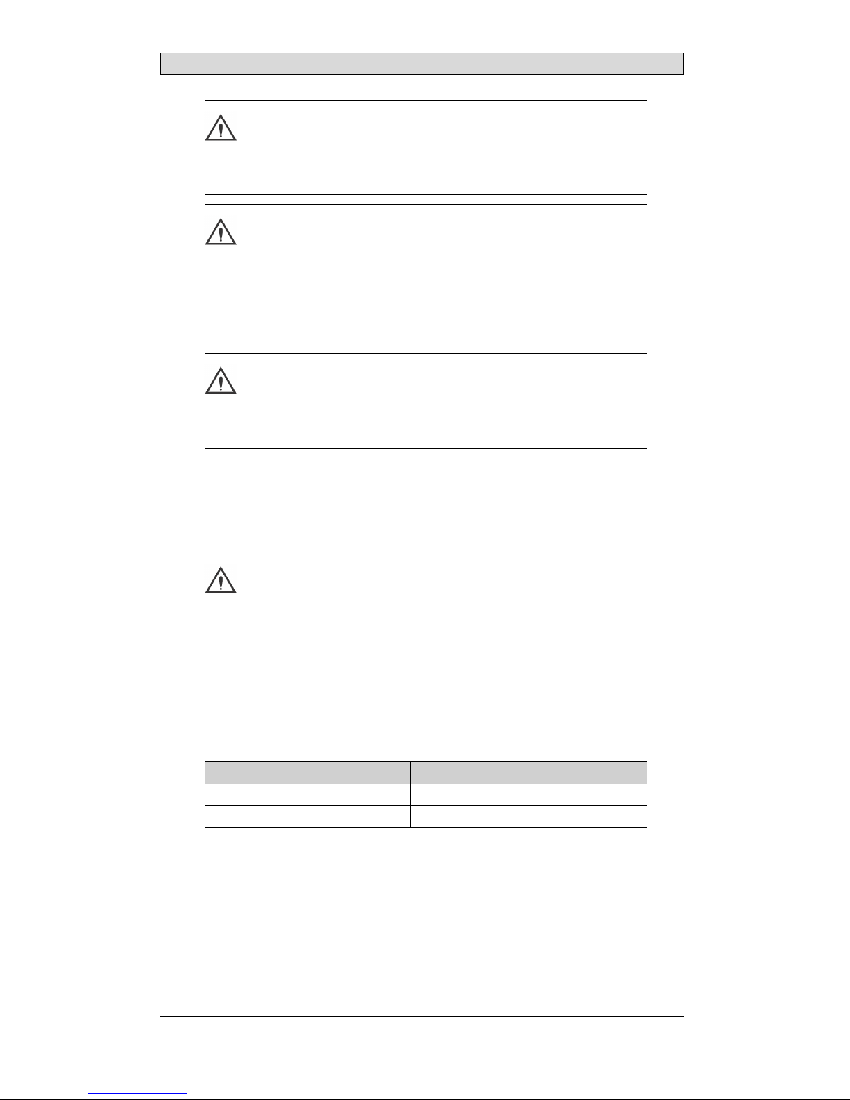
2.1 Space Requirements
• Installation plate thickness: 1.5 - 7.5 mm (0.06 - 0.3 inch)
• Space requirements when installingthe operator panel:
50 mm
152 mm
202 mm
(2.0 inch)
50 mm
(2.0 inch)
100 mm
(4.0 inch)
100 mm
(4.0 inch)
100 mm
(4.0 inch)
57 mm
(2.24 inch)
(7.95 inch)
(5.98 inch)
Caution:
The openings on the enclosure are for air conve
ction. Do not cover these openings.
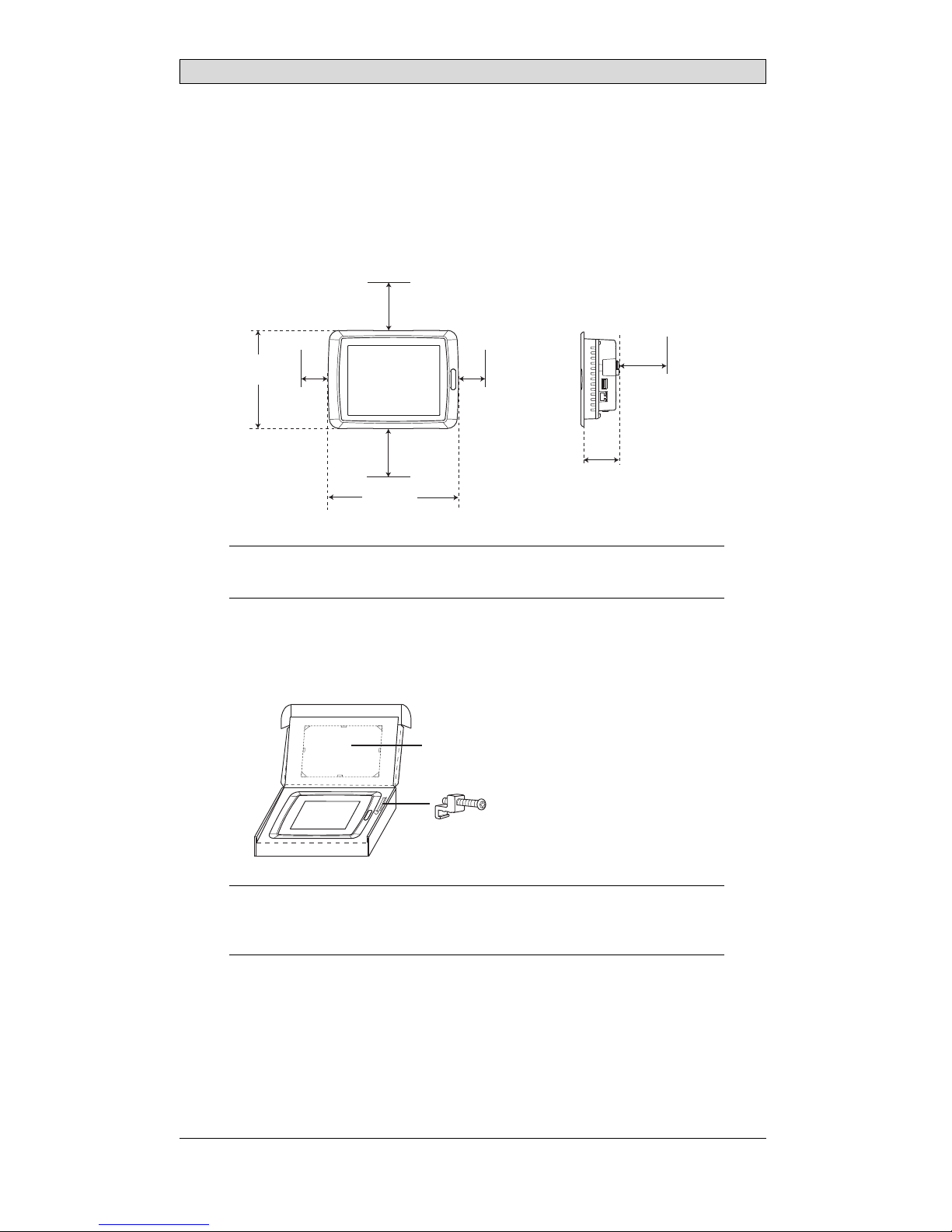
2.2 Installation Process
1.
Unpack and check the delivery. If dama
ge is found, notify the supplier.
x 4
Panel cut out 180 x 130 mm
(7.09 x 5.12 inch)
Note:
Place the operator panel on a stable surface during installation.
Droppingit or lettingit fall may cause damage.
Beijer Electronics, MAEN809F
7
Page 8
Installation
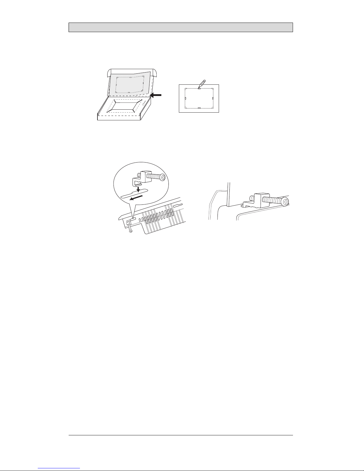
2.
Place the panel cut out where the operator panel is to be situated, draw along
the outer sides of the holes andcut according to the markings.
3.
Secure the operator panel in position, using all the fastening holes and the
provided brackets and screws:
x 4
0.5 - 1.0 Nm
Beijer Electronics, MAEN809F
8
Page 9

Installation
4.
Connect the cables in the specified order,according to the drawing and steps
below.
Caution:
• The operator panel must be brought to ambient temperature before itis started
up. If condensation forms, ensure that the operator panel is dry before connecting
it to thepower outlet.
• Ensurethat the operator panel and the controller system have the same electrical
grounding(reference voltage level), otherwise errors in communication may
occur.
• Ensure that the voltage and polarity of the power source is cor rect.
• Separatehigh voltage cables from signal and supplycables.
• Shielded communication cables are recommended.
24V DC
RS422/
RS485
RS232
24V DC
A
C
D
Controller
Power
B
Ethernet
– Connect cable A.
– Connect cable B, using an M5 screw and a grounding conductor (asshort
as possible), that is sized correctly according to local electrical codes.
– Connect cable C.
– Connect cable D.
5.
Carefully remove the laminated film over the operator panel display, to avoid
static electricity that could damage the panel.
Beijer Electronics, MAEN809F
9
Page 10

Installation
2.2.1 Mode Switches
All mode switches must be in OFF position during operator panel use.
Themodeswitchesshouldnotbetouchedunlessbyqualifiedpersonnel.
1 2 3 4
ON DIP
1 2 3 4
ON DIP
2.2.2 Connections to the Controller
Forinformation about the cables to be used when connecting the operator panel to
the controller, please refer to the help file for the driver in question.
2.2.3 Other Connections and Peripherals
Cables, peripheral equipment and accessories must be suitable for the application
and its environment. For further details or recommendations, please refer to the
supplier.
Beijer Electronics, MAEN809F
10
Page 11

Technical Data
3TechnicalData
Parameter EXTER T60/T60m
Frontpanel,WxHxD 202x152 x6mm
Mountingdepth 57 mm (157 mm including clearance)
Front panel seal IP 66
Rear panel seal IP 20
Keyboard
material/Front
panel
Touch screen: Polyester on glass, 1 million finger touch
operations. Overlay: Autotex F157 or F207*.
Reverse side
material
Powder-coated aluminum
Weight 0.9 kg
Serialport
RS422/RS485
25-pin D-sub contact, chassis-mounted female with
standard locking s crew s 4-40 UNC
Serialport RS232C 9-pin D-sub contact, male with standard locking screws 4-40
UNC
Flashmemory for
application
12 MB (inc l. fonts)
Ethernet ShieldedRJ 45
USB Host type A (USB 1.1), max outputcurrent 500 mA
Realtimeclock ±20 PPM + error because of ambient temperature. Total
maximumerror: 1 minute/month at 25°C.
Tempera t u r e coefficient: -0.034±0.006 ppm/°C
2
Real time clock
battery
CR2450 (UL and cUL: Sanyo or Panasonic)
Minimumlifetime: 3 years
Power consumption
at rated voltage
Normal: 0.2 A
Maximum: 0.4 A
(For T60c and for T60m with hardwareversion lower than
07600: Normal: 0.25A, Maximum: 0.45 A)
Display 320 x 240 pixels,T60: TFT-LCD, 64K colors.
(For T60c: transmissive color STN-LCD, 64K colors; for
T60m: TFT-LCD, 16 greyscales; for T60m with hardware
versionlower than 07600: transmissive monochrome
STN-LCD.)
T60: LED backlight lifetime at the ambient temperatureof
+25 °C: >50,000 h.
(For T60c: CCFL backlight lifetime(at 25°C): >75,000 h.
For T60m with hardware version lowerthan 07600: CCFL
backlightlifetime (at 25°C): >58,000 h.)
Activearea of
display, W x H
115.2 x 86.4 mm
Fuse Internal DC fuse , 2.0 AT, 5 x 20 mm
Powersupply +24 V DC (20 - 30 V DC). Powersupplyconnector.
CE: The power supply must conform with the requirements
accordingto IEC 60950and IEC 61558-2-4.
UL and cUL: The power supply must conform with the
requirements for class II power supplies.
Beijer Electronics, MAEN809F
11
Page 12

Technical Data
Parameter EXTER T60/T60m
Ambient
temperature
Verticalinstallation: 0 ° to +50 °C
Horizontal installation: 0 ° to +40 °C
Storagetemperature -20 ° to +70 °C
Relativehumidity 5 - 85 % non-condensed
Approvalsand
certifications
Information is available onthe web site
www.beijerelectronics.com
*SeesectionChemical Resistance for more information.
Beijer Electronics, MAEN809F
12
Page 13

Chemical Resistance
4 Chemical Resistance
4.1 Metal Casing
The frame and casing material is powder-coated aluminum. This powder paint
withstands exposure to the following chemicals without visible change:
Acetic acid 10% Phosphoricacid4%
Citricacid 10% Phosphoricacid10%
Diesel Sea water
Distilled water Sodiumchloride 2%
Edibleoil Sodiumchloride 20%
Fuel oil Sulphuric acid 20%
Hydrogen peroxide 3% Tap water
The powder paint shows limited resistance to the f
ollowing chemicals at room
temperature:
Butanol Nitric acid 3%
Hydrochloric acid 5% Nitric acid 10%
Isopropyl alcohol Phosphoricacid 43%
Na-hypochlorite10% Turpentine
Note:
If exposure to any of theabove chemicalsis demanded,it is recommended to first test
the chemical in a hidden spot of the metal casing.
Thepowderpaintshowslittleornoresistancetothefollowingchemicalsatroom
temperature:
Acetic acid, conc. Methyl-ethyl ketone Toluene
Acetone Nitric acid 30% Trichlorethylene
Ammonia5% Phenol Xylene
Ammonia,conc. Sodiumhydroxide 5% 97octanunleaded petrol
Ethyl acetate Sodium hydroxide 30% 98 octan leaded petrol
4.2 Touch Screen and Overlay Material
4.2.1 Autotex F157/207
Autotex F157 or F207 covers the overlay surrounding the screen.
Beijer Electronics, MAEN809F
13
Page 14

Chemical Resistance
Solvent Resistance
Autotex F157/F207 withstands exposure of more than 24 hours duration under
DIN42115Part2tothefollowingchemicalswithoutvisiblechange:
Acetonitrile DieselDowney / Lenor
1
Phosphoricacid(<30%)
Ajax / Vim in solution EthanolPotassiumferricyanide
Alkalicarbonatesolution1Glycerine Potassiumhydroxide
(<30%)
Ammonia(<40%)
1
Glycol Pure Turpentine
Acetic acid (<50%) Gumption
1
SBP 60/95
1
Ariel powder in solution1Hydrochloricacid (<36%) Sulfuricacid (<10%)
Bleach
1
Linseed oil Tomato ketchup
Castoroil Methanol Trichloroacetic acid
(<50%)
Caustic soda (<40%)
1
Nitric acid (<10%) White Spirit
Cutting oil Paraffinoil Windex
1
Cyclohexanol Persilpowder in solution1Wisk
Diacetonealcohol Petroleum spirit
1
-
1
Extremely faint glossing of the texture was noted.
Autotex withstands DIN 42 1
15 Part 2 exposure of up to 1 hour duration to glacial
acetic acid without visib
le change.
Autotex is not resistant to high pressure steam at over 100 °C or the following
chemicals:
Concentratedmineral acids Benzyl alcohol
Concentrated caustic solution Methylene chloride
Outdoor Use
In common with all polyester based films Autotex F157/F207 is not suitable for
use in conditions of long term exposure to direct sunlight.
4.2.2 Touch S
creen Surface
The touch screen surface on the operator panel withstands exposure to the
following solvents without visible change:
Solvents Time
Acetone 10 minutes
Isopropanol 10 minutes
Toluene 5 h o urs
Beijer Electronics, MAEN809F
14
Page 15

Chemical Resistance
4.2.3 Touch Screen Protector
Forharsh environments and exposure to outdoor conditions, it is recommended
to use a protective film to guard the touch screen from damage. These optional
parts can be ordered from Beijer Electronics.
Beijer Electronics, MAEN809F
15
Page 16

Operator Panel Drawings
5 Operator Panel Drawings
5.1 Communication Ports
RS-232
RS-422
RS-422/485
RS-485
Ethernet
USB
Beijer Electronics, MAEN809F
16
Page 17

Operator Panel Drawings
5.2 EXTER T60/T60m Outline
Beijer Electronics, MAEN809F
17
Page 18

Additional Installation Tips
6 Additional Installation Tips
When experiencing communication problems in for example noisy environments
or when operating close to temperature limits, the following recommendations
are to be noticed.
6.1 Grounding the Operator Panel
1
2
3
4
5
6
Door
Operator panel
Ferrite core
Mounting plate in the cabinet
Power supply
24 V DC
5350
The operatorpanel’smounting clamps do not provide a secure grounding
connection between the panel and the device cabinet, see 1 in drawing above.
1.
Connect a wire that is sized correctl
y according to local electrical codes
between the operator panel’s quick
-connect plinth and the panel’s chassis, see
2indrawingabove.
2.
Connect a 6 or 4 mm
2
wire or grounding braid between the panel’schassis and
the closest grounding point on the door,see 3 in drawing above.
3.
Connect a strong but short grounding braid between the door and the device
cabinet,see 4 in drawing above.
4.
Twist the cables onto the 24 V DC feed, see 5 in drawing above.
2 turns around the ferrite core provide 4 times the suppression of 1 turn.
3 turns around the ferrite core provide 9 times the suppression of 1 turn.
A ferrite core suppresses disturbances to the 24 V feed, see 6 in drawing above.
Note:
The grounding wires should be short and the conductor should havea large area.
A long, thin grounding wire has a very high impedance (resistance) at high frequencies
and will not guide disturbances to the ground.
Multi-wireconductors are better than singlewireconductorswiththesamearea.
A braided conductor wire withthe same area is even better. The best is a short, thick
grounding braid.
Beijer Electronics, MAEN809F
18
Page 19

Additional Installation Tips
6.2 Ethernet Connection in the Panel
1
2
3
4
5
1-1
2-2
3-3
8-8
RJ45
RJ45
RJ45
RJ45
RJ45
RJ45
RJ45
RJ45
Industrial Ethernet
Operator panel
Operator panel
Operator panel
Operator panel
Shielded
Short and
unshielded
0.1 uF
250 V
5351
In some industrial units for Ethernet, the RJ45 contact’s shield is connected to the
chassis via a capacitor,see 1 in drawing above.
The operator panel’sEthernet shield is directly
connected to thechassis, see 2 in
drawing above.
1.
Check whetherthe other Ethernet unit has its shield directly grounded or
grounded via a capacitor.
Note:
In many cases, connecting the shielded Ethernet cabling to the chassis at both ends is
inappropriate. Hum or grounding loops can occur. Unshielded cabling may even result
in fewer communication errors.
A good solution may be to use a shielded Ethernet cable, but to connect the shield
at one end only.
One option is to break the shield, see 3 in drawing above.
A more elegant method is to expand the shielded Ethernet cabling with a piece of
unshielded Ethernet cable, see 4 in drawing above.
You can ground the shield via an external 0.1 µF/250 V plastic capacitor,see 5 in
drawing above. This will connect the HF transients to the ground.
Beijer Electronics, MAEN809F
19
Page 20

Additional Installation Tips
6.3 To Achieve Better EMC Protection
• Useshielded cables for RS232 communication.
• Usetwisted pair and shielded cabling for RS422 and RS485.
• Usethe cabling intended for the bus type; Ethernet, Profibus, CC-Link,
CAN, Device Net etc.
• Install and connect according to applicable specifications for the relevant bus
standard.
• Useshielded cabling for Ethernet, preferably with foil and a braided shield.
• D-sub covers should be shielded, and the shield should be connected to the
cover 360° where the cable enters.
• Connect the shield at both ends.
Shielded cable
Not same potential
Ground plane 1 Ground plane 2
Ground plate Ground plate
in another building
0.1 uF/250 V
5352
With longer distances, there is a risk that the ground potential may be different.
In that case, the shield should only be connected at one end. A good alternative
is to connect the other end of the shield to the ground via a 0.1 µF/250 V plastic
capacitor. Both ends are then connected to the ground in terms of HF, but only
connected to the ground at one end in terms of LF, thus avoiding the 50 Hz
grounding loops.
Metal cabinet Metal cabinet
Terminal or connector Terminal or connector
EMC cable gland Plastic cable gland
Shielded cable Shielded cable
Short distance
Cable clamp
in steel
5353
1.
UseanEMCcableglandorregul
ar plastic cable gland, remove the outer jacket
andconnecttheshieldtothe
installation plate with a 360 ° metal cable clamp.
2.
Place the 24 V DC and communications cabling in one cable trunk/cable duct
and 230/380 V AC in another. If the cables need to be crossed, cross them at
90 ° only. Avoidcombining the cabling for stronger 24 V DC outputs with
the communication cabling.
Ferritecores that are snapped onto the shielded cabling may remove minor
disturbances. Large ferrite pieces that are snapped onto unshielded cabling and
where the wires go 2-4 times around the cores are approximately 5-25 times more
efficient.
Beijer Electronics, MAEN809F
20
Page 21

Additional Installation Tips
6.4 Ambient Temperature
The maximum ambient temperature for the operator panel is provided in the
specifications. The ambient temperature refers to the temperature in the device
cabinet which coolsthe panel’s electronics.
Operator
panel
Power
Power
Power
30 °C outside
Top
50 °C inside
Bottom
40 °C inside
Middle
45 °C inside
Airflow
Axial fan
120 x 120 mm
5354
Inmostcases,theambienttemperaturefortheoperatorpanelissignificantly
higher than the device cabinet’s ambient temperature.
If the cabinet is tall and there are a number of hea
t-generating devices, the
temperature at the top of the cabinet will be con
siderably higher than the
theoretical temperature increase that would
be expected. All electronics are
sensitivetoheat. Thelifespanofanelectro
lytic capacitor is cut in half with an
8-10 °C increase in temperature. A 15-20 °C t
emperature increase results in a
quarter of the lifespan etc.
Rittal has a good program for estimating the anticipated average temperature in
the cabinet as well as a large program for controlling the temperature in the device
cabinet.
An enamel-coated steel cabinet has
a radiant heat value of 5.5 W/m
2
and degrees
C.
Installing a fan inside the cabinet will even out the temperature, while moving air
provides considerably better cooling than still air. A suitable fan is a 120 x 120 mm
axial fan, available in 24 V DC, 115 and 230 V AC.
Installthefansothatitsit
s in the cooler area and blows cold air against the operator
panel. If the fan is mounted
at the top and sucks warm air upwards, the fan’s
ambient temperature will
be higher, resulting in a shorter lifespan.
Agoodfanwithaball-bearingmountinghasanexpectedlifespanofatleast
40,000 hours (not a guaranteed lifespan) at 40 °C. This corresponds to at least 4
years of continuous use. If a thermostat is installed, the fan only operates when
needed.
Large graphic termi
nals draw only one fifth of the current when the background
lighting is off. Th
e loss effect drops from e.g. 25 W to only 5 W.
An approximate value of the net power consumption for the operator panel can
be calculated by multiplying the supply voltage withthe current drawn by the
operator panel. This is assuming that all supplied power is transformed to heat.
Beijer Electronics, MAEN809F
21
Page 22

Additional Installation Tips
6.5 Safety
Most of the operator panels are fed with 24 V DC.
4
1
2
4
3
4
Power supply
230 V AC to 24 V DC
Power supply
230 V AC to 24 V DC
Power supply
230 V AC to 24 V DC
Operator panel
Operator panel
Operator panel
Distance?
Small controller with expansion unit
+24 V
+24 V
+24 V
0 V
0 V
0 V
230 V AC
COM1
COM100
Ch0
Ch1
Ch100
Ch101
5355
If a power supply that meets safety standards is used and only feeds the operator
panel, there is no problem. See 1 in drawing above.
However, if a 24 V unit that also feeds other units is used, there is reason to be
cautious, see 2 in drawing above. The operator panel does not have insulation
that meets safety requirements in the eventof a potential short circuit between
230 V AC and 24 V DC. It is assumed that the 24V feed is secure, for example,
SELV according to EN 60950 (protection against electric shock) and UL 950.
Note:
Here is an example that explains why a secure 24 V DC feed can be ruined by mixing
24 V r elaycontacts with 230 V AC relay contacts in a smaller controller. Check that the
clearancesand creepage distances between 24 V DC and 230 V AC ful fill EN 60950 or
UL 950. If not, input a separate 24 V unit into the operator panel.
If there is a substant
ial distance between the relay contacts for 24 V DC and
230 V AC, it is OK to us
e the same 24 V devices for all feeds. See 3 in drawing
above.
Connect 0 V on the 24 V feed to the ground, see 4 in drawing above. This offers
three advantages:
• Safety is incre
ased. The 24 V feed will not be live in the event of a faulty
connection or
short circuit between 0 V (24 V) and 230 V phase.
• Tr a n s i e n t s o n
the 24 V feed are connected to the ground.
• No risk that t
he 24 V feed is at a highlevel in relationship to the ground. This
is not unus
ual since there is high static electricity.
Beijer Electronics, MAEN809F
22
Page 23

Additional Installation Tips
6.6 Galvanic Isolation
USB
USB
RS232RS422/485
+24 V DC
0 V
Filter
DC/DC
galvanic isolation
VCC
0 V (GND)
DC/AC
CFL
Ethernet
Internal electronic
1.5 m
5356
The operator panel has galvanic isolation against the 24 V DC feed but no galvanic
isolation between the communication ports for RS232, RS422/485 and USB.
Only the Ethernet connection has galvanic isolation.
* *
*
***
**
*
Operator panel Modular controller Printe
r
PCPC
Not same ground potential
* = Internal 0 V (GND) connection
Power CPU COM COM2
RS422 RS232 USB
5357
When a PC is connected to the panel, the panel’sinternal 0 V (G
ND) will be
connected to the protective ground via the PC.
A number of USB devices can have the shield connected together with the
protective ground. Here, the panel’s0 V (GND) is connected to the protective
ground when, for example, a USB memory stick, keyboard or similar device is
plugged in.
If a number of units are connected that have a 0 V a
nd a ground connection, and
these are connected to various grounding poin
ts, there is a substantial risk of
problems. Grounding currents go through com
munication cables, the rear plate
of the controller, and internally in th
e operator panel, and can cause errors.
Use external units to improve communication and achieve galvanic isolation.
Westermo has good industry-standard insulators that are also insulated from the
24 V DC feed.
Note:
It is very important to make sure that the 24 V feed inthe external insulation unit is not
connected to one of the communication outlets. If it does not have 100% insulation
againstthe 24 V feed, disturbances and grounding currents from the 0 V on the 24 V
side will disrup t communication.
Using this type of unit solves one problem but creates a larger problem! A substandard
installationmay work now,butproblemsmay arise when other devices are connected.
Beijer Electronics, MAEN809F
23
Page 24

Additional Installation Tips
6.7 Cable and Bus Termination RS485
• Use shielded and twisted pair cable. The pair capacitancemay not exceed 52.5
pF/m and area at least 0.25 mm
2
(AWG 24), if you want to use the maximum
transfer distance and maximum transfer speed.
• 0 V,the reference voltage for communication should be included in
the cabling. With two-way communication use two pairs; one pair for
communication andone pair for 0 V.
• The shield must be grounded at one end. The other end is usually grounded,
but with longer distances or when there is a difference in the ground potential,
theshieldshouldbeconnectedtothegroundvia0.1μF/250Vplastic
capacitor to prevent ground current in the braided shield. A number of
manufacturers recommend that the shield be grounded at each node. Various
manufacturers have different systems for bus termination. The RS485
standard does not describe how the “Fail Safe” function would be carried out,
justthatthesystemshouldbeabletohandletheerror.
Depending on the recipients’ design, the bus wires may be on the same level or
require pull-up or pull-down to ensure that no faulty signals are detected when the
bus is in resting mode (all transmitters are disconnected).
1 23
4
+5 V
0 V
1 K
1 K
120 ohm 120 ohm
120 ohm
+5 V
+5 V
0 V
0 V
0 V
0 V
0 V
0 V
1 K
1 K
1 K
1 K
VCC
VCC
(120 ohm)
Inside operator panel
Operator
panel
RS422
CAB8CAB8 Bus
RS485
Shield
Bus termination
5358
2
14
15
6
19
7
8
1
2
3
4
5
6
7
8
2
15
3
16
17
4
14
8
7
55
50
17
1 2 3 4 5 6 7 8
Some (older) operator panels had pull-up and pull-down resistance except for
the actual bus termination at 120 Ω, similar to Westermoand Profibus. See 1 in
drawing above.
Newer panels have another type of recipient, so-called built-in “FailSafe”, where
simple bus termination resistance is sufficient. See 2 in drawing above.
If other nodes on the RS485 network require pull-up and pull-down and the
operator panel is at one end of the loop, one of the following procedures can be
carried out:
• Connect two 1 kΩ / 0.25 W resistors in the 25-pole D-sub contact. See 3 in
drawing above. Set jumper pins 6-19.
• UseCAB8. It offers the option of bus termination with pull-up/-down. It
isalsoeasytoconnectthebuscableviathescrewterminalblock. See4in
drawing above.
Beijer Electronics, MAEN809F
24
Page 25

Head office
BeijerElectronics AB
Box 426
20124Malmö,Sweden
www.beijere
lectronics.com/ +46 40 358600
 Loading...