

Page 1
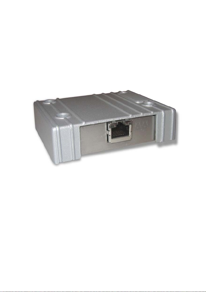
Expansion Module for Ethernet
Installation
MAEN911A 2008-11
English
Page 2

Installation of Expansion Module for Ethernet
The expansion module is used for the operator panel to communicate via Ethernet. The correct driver must be installed in the operator panel.
Important
Read the entire installation instructions prior to installing and using this equipment. Only qualified personnel may install, operate or repair this equipment.
Users must acquire the appropriate knowledge to use the equipment properly.
The manufacturer does not assume any responsibility for modified, altered or
renovated equipment.
THE MANUFACTURER SHALL NOT BE LIABLE TO ANYONE FOR
ANY DIRECT, INDIRECT, SPECIAL, INCIDENTAL, OR CONSEQUENTAL DAMAGES RESULTING FROM THE INSTALLATION, USE OR REPAIR OF THIS EQUIPMENT, WHETHER ARISING IN TORT,
CONTRACT, OR OTHERWISE. BUYER’S SOLE REMEDY SHALL BE
THE REPAIR, REPLACEMENT, OR REFUND OF PURCHASE PRICE,
AND THE CHOICE OF THE APPLICABLE REMEDY SHALL BE AT
THE SOLE DISCRETION OF THE MANUFACTURER.
Attention:
Observe pr ecautions for handling el ectrostatic sensitive devices.
Technical Data
Size, W x H x D 86.7 x 69.6 x 23.5 mm
Weight 0.11 kg
Band rate 10 Mbit/s
Page 3

Installation of Expansion Module for EthernetInstallation of Expansion Module for Ethernet
Space Requirements
35 mm
23.5 mm
Installation
1. Unpack and check the delivery. If damage is found, notify the supplier.
M3x6 - 4 pcs Distances - 4 pcs
Note:
Place the panel on a stable surface during installation. Dropping it or letting it fall
may cause damage.
2. Disconnect the operator panel from the power supply.
3. Remove the plastic cover from the expansion port.
4. Secure the expansion module in position, using the provided screws.
5. Connect the operator panel to the power supply.
Page 4

The LEDs on EM-Ethernet
Green LED
Yellow LED
The expansion module has two LEDs, with the following functions:
TxD, green. The LED is activated by Ethernet transmit activity.
RxD, green. The LED is activated by Ethernet receive activity.
LINK, yellow. The LED is activated when the Ethernet (twisted pair) cable is
connected correctly.
Settings in the Configuration Tool
Double-click on the Peripherals folder in the Project Manager in the configuration tool for the operator panel.
Right-click on Expansion Port and select EM-Ethernet. Then drag Controller
with the corresponding driver or TCP/IP connection to the Fieldbus icon. To
change the selected driver, select Properties from the Project menu.
For further information, please see the information for the driver.
 Loading...