

Page 1

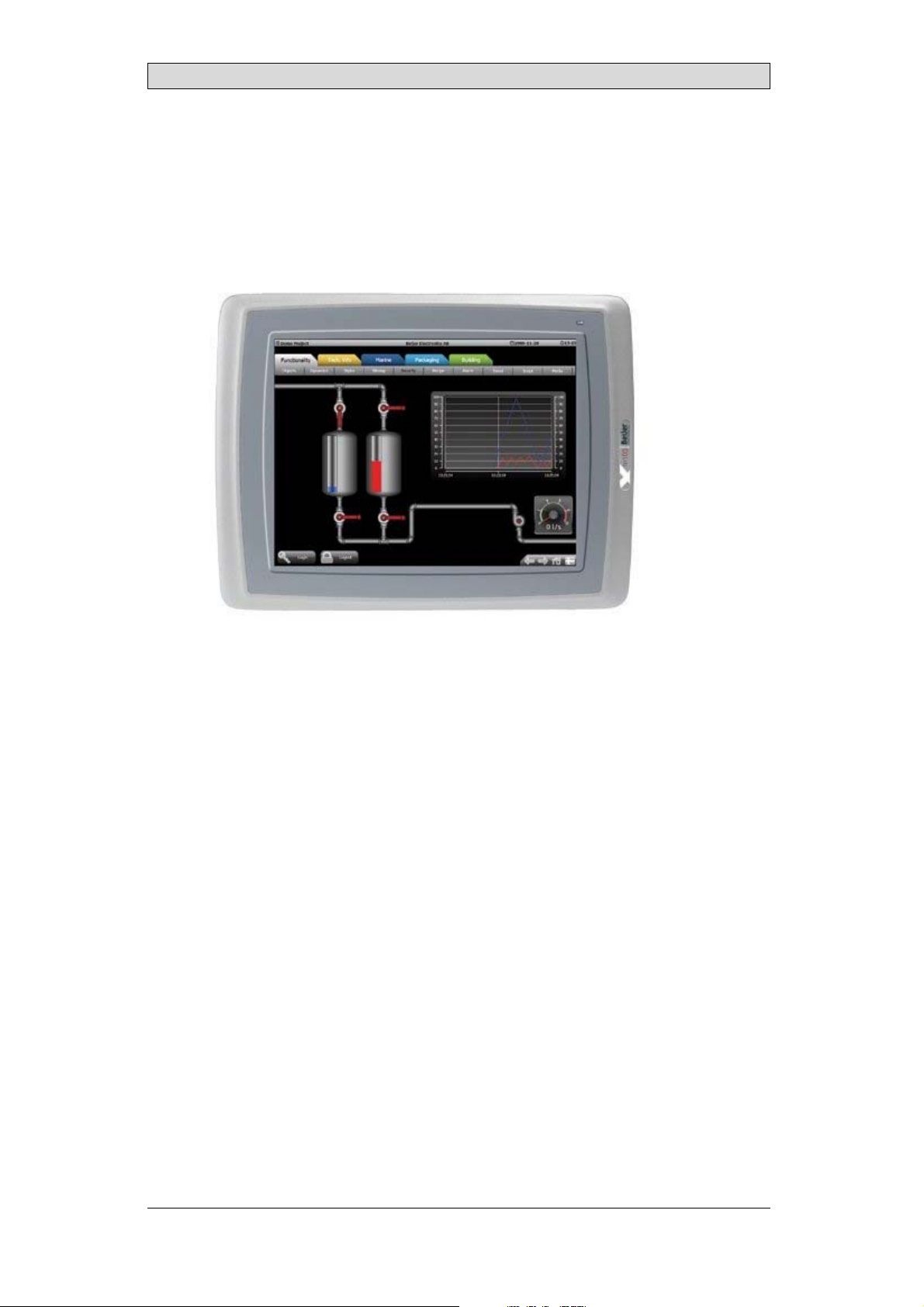
EPCTA100AM
Service&MaintenanceManual
MAEN043,2010-12
English
Page 2

Service&Maintenancemanual for EPCTA100AM
Foreword
This manual contains detailed information aboutEPC TA100 AM, including
descriptions of various actionsthat can be carried out in order to maintain or
update the PanelPC hardware and software.
The manual contains descriptions of basicmaintenance and replacement of
common parts in EPC TA100 AM.
The followingother manuals are available for EPC TA100 AM:
EPC TA100 AM installation manual (MAEN040x)for information regarding
installation.
Foreword
Order no: MAEN043
Copyright © 2010-12 Beijer Electronics AB. All rights reserved.
The information in this documentis subjectto changewithoutnoticeandisprovidedasavailableatthe
time of printing. Beijer Electronics A B, including all its group companies, reserves the right to change any
information w ith ou t updating thispublication. Beijer ElectronicsAB assumes no responsibility for any
errors that may appear in this document. Read the entire installationmanual priorto i nstalling and using
this equipment. Only qualified perso nnel may install, operate or repair this equipment. Beijer Electronics
AB is not responsible for m odified, altered or renovated equipment. Because the equipment has a wide
range of applications, users must acquire the appropriateknowledgetousetheequipmentproperlyintheir
specific a pplications. Personsresponsible forthe application and the equipment must th emselves ensure
that each application isin compliance with all relevant requirements,standards and legislation in respect to
configuration and safety. Only partsand accessoriesmanufactured accordingto specifications set byBeijer
Electronics AB may be used.
BEIJER ELECTRONICSAB, INCLUDING ALL ITS GROUP
COMPANIES,SHALL NOT BE LIABLE TOANYONE FOR ANY
DIRECT, INDIRECT, SPECIAL, INCIDENTALOR CONSEQUENTIAL
DAMAGES RESULTING FROM THE INSTALLATION,USE OR
REPAIROF THIS EQUIPMENT, WHETHER ARISING INTORT,
CONTRACT, OR OTHERWISE. BUYER'S SOLE REMEDY SHALL BE
THE REPAIR,REPLACEMENT, OR REFUND OF PURCHASE PRICE,
AND THE CHOICE OF THEAPPLICABLE REMEDY SHALL BE AT
THE SOLE DISCRETION OFBEIJER ELECTRONICS AB .
BeijerElectronics, MAEN043
Page 3

Contents
Contents
1 Safety Precautions ....................................................... 5
1.1 General ...........................................................
1.2 During Installation ..............................................
1.3 During Use .......................................................
1.4 Service and Maintenance ........................................
1.5 Dismantling and Scrapping .....................................
2 Introduction ............................................................. 7
2.1 EPC TA100 AM .................................................
2.2 Maintenance .....................................................
2.3 Service andRepairs ..............................................
2.4 Dismantling and Scrapping .....................................
2.5 Contact andSupport ............................................
3 Installation ............................................................... 10
3.1 Space Requirements .............................................
3.2 Installation Process ..............................................
3.2.1 Other ConnectionsandPeripherals ................ .............
4 TechnicalData ........................................................... 13
5 ChemicalResistance .................................................... 14
5.1 Metal Casing .....................................................
5.2 Touch Screen and Overlay .......................................
5.2.1 AutotexF157/207 .......... .....................................
5.2.2 TouchScreenSurface ............. ...............................
5.2.3 AutoflexEB ........ ..............................................
6 Hardware Replacement ................................................. 17
6.1 Cables .............................................................
6.2 Replacing the Rear Cover ........................................
6.3 Replacing the Display/Display Cab
6.3.1 CalibratingtheTouch Screen ....................................
le ..........................
6.4 ReplacingtheCompleteFront ..................................
6.5 Replacing the Backlight .........................................
6.6 Available SpareParts for EPC TA
7 Additional Installation
Tips ............................................
100 AM ......................
7.1 GroundingthePanelPC ........................................
7.2 Ethernet Connection in t
7.3 To Achieve Better EMC Pr
he PanelPC ..........................
otection .............................
7.4 Ambient Temperature ...........................................
7.5 Safety .............................................................
7.6 Galvanic Isolati
7.7 Cable and Bus Term
on ................................................
ination RS485 .............................
8 Fault Tracing ............................................................. 32
9 Software .................................................................. 34
9.1 General Infor
9.1.1 Software Pro
9.2 Update or C
9.2.1 Backup a
mation about Software ...........................
ducts ...................... .........................
ustomize Software ..................................
ndRecovery ..................................... .......
10
10
12
14
15
15
16
16
17
18
19
20
22
23
24
25
25
26
27
28
29
30
31
34
34
35
35
5
5
6
6
6
7
8
8
8
9
BeijerElectronics, MAEN043
Page 4

Contents
10 EnvironmentalAspects ................................................. 36
10.1 General Environmental Aspects ................................
10.2 Environmental Impact of thePanelPCs ........................
10.2.1 MechanicalComponents ........................................
10.2.2 Electronics ............ ...........................................
10.3 Recycling .........................................................
10.4 Environmental Impact Report ..................................
36
36
36
36
37
37
BeijerElectronics, MAEN043
Page 5

Safety Precautions
1SafetyPrecautions
Both the installer and the ownerand/o r operator of the Panel PC must readand
understand this installation manual.
1.1 General
• Read the safety precautions carefully.
• Check the delivery for transportation damage. If damage is found, notify the
supplier as soon as possible.
• Do not use the PanelPC in an environment with high explosive hazards.
• The supplier is not responsible for modified, altered or reconstructed
equipment.
• Use only parts and accessories manufactured accordingto specifications of
the supplier.
• Read the installation andoperating instructions carefully before installing,
using or repairingthe Panel PC.
• Neverallowfluids,metalfilingsorwiringdebristoenteranyopeningsinthe
PanelPC. This may cause fire or electrical shock.
• Only qualified personnel may operate thePanel PC.
• Storing the Panel PC where the temperatureis lower/higher than
recommended in this manual can causethe LCD display liquid to
congeal/become isotopic.
• The LCD display liquid contains apowerful irritant. In caseof skin contact,
wash immediately with plenty ofwater. In case of eye contact, hold theeye
open,flushwithplentyofwaterandgetmedicalattention.
• Thefiguresinthismanualservesanillustrativepurpose. Becauseofthemany
variables associated with any particular installation, the suppliercannot
assume responsibility for actual use based onthe figures.
• The supplier neither guarantees that the Panel PC is suitable for your
particular application, nor assumes responsibility for your productdesign,
installation or operation.
1.2 DuringInstallation
• The Panel PC is designed forstationary installation on a plane surface, where
the following conditions are fulfilled:
– no high explosive risks
– no strong magnetic fields
– no direct sunlight
– no large, sudden temperature changes
• Install the product accordingto the accompanying installation instructions.
• Ground the productaccording to the accompanying installation instructions.
• Only qualified personnel may install thePanel PC.
• Separate the high voltage, signal andsupply cables.
• Make sure thatthe voltage and polarity of the power sourceis correct before
connecting the productto the power outlet.
• Peripheralequipment must be appropriate for the application and location.
BeijerElectronics, MAEN043
5
Page 6

Safety Precautions
1.3 DuringUse
• Keep the Panel PC clean.
• Emergency stop and other safety functionsmay not be controlled from the
Panel PC.
• Do not use too muchforce or sharp objects when touching the keys, touch
screenetc.
1.4 ServiceandMaintenance
• Only qualified personnel should carry out repairs.
• The agreed warranty applies.
• Before carrying out any cleaning or maintenance operations,disconnect the
equipment from the electricalsupply.
• Clean the display and surrounding front coverwith a soft cloth and mild
detergent.
• Replacing the battery incorrectly may result in explosion. Only use batteries
recommended by the supplier.
1.5 DismantlingandScrapping
• The PanelPC or parts thereof shall be recycledaccording
• The followingcomponents contain substances that migh
to health and theenvironment: lithium battery
display.
, electrolytic capacitor and
to local regulations.
t be hazardous
BeijerElectronics, MAEN043
6
Page 7
2Introduction
This manual describes howto maintain the EPC TA100 AM.
2.1 EPCTA100AM
Introduction
The following drawingsare available for EPC TA100 AM:
• Outline drawing
• Panelcut-out
BeijerElectronics, MAEN043
7
Page 8

Introduction
2.2 Maintenance
Carefully read the instructions beforebeginning maintenance on the Panel PC.
• Only qualified personnel shouldc arry out maintenance.
• The agreed warranty andlicense agreements apply.
• Any damage to thePanel PC caused by personnelinvalidates the warranty.
• Before carrying out any cleaning or maintenance operations,disconnect the
PanelPC from the power supply.
• Clean the display and surrounding front coverwith a soft cloth and mild
detergent. Recommended cleaning fluids for the display are water and IPA
(Isopropyl Alcohol or Hexane).
• Replacing the battery incorrectly may result in explosion. Only use batteries
recommended by the supplier.
• A 6-month warranty onall service parts is provided.
Maintenance personnel are permitted to carry out the following actions:
• Replacing the Rear Cover
• Replacing the Display/Display Cable
• Replacing the Complete Front
• Replacing the Backlight
2.3 ServiceandRepairs
• Only accredited companies arepermitted to perform service and repairs.
• Ifanon-accreditedcompanyconductsanykindofserviceorrepair,theagreed
warranty will be invalidated.
• If training is required,c ontact the supplier.
• All maintenance should be performed in a 15-30°C temperature range.
• Any damage to thePanel PC caused by personnelinvalidates the warranty.
• Contracts with customers supersede theinformation in this document.
2.4 DismantlingandScrapping
• The PanelPC, or parts thereof, shall be recycled according to local
regulations.
• The followingcomponents contain substances that might be hazardousto
health and the environment: lithium battery, electrolytic capacitor, display.
BeijerElectronics, MAEN043
8
Page 9

Introduction
2.5 ContactandSupport
If you want toreport a fault or have a question about the Panel PC, please contact
your local supplier orfill out the form on the web site.
1.
Enter the web site www.beijerelectronics.com and select Support.
2.
Select Contact in themenu. Makesure to provide informationabout type
number, serial number, environment and aninstallation description.
The form will be sent tothe manufacturer’s help desk and they will answer your
question or register yourimprovement/fault.
To ensure quick resolution, provide asmany details as possible in your report.
Include the date and time whenthe problem occurred, a description of what you
were trying to do, the detailed steps you tookthat led up to the problem,and
details about any error messages received.
BeijerElectronics, MAEN043
9
Page 10
3Installation
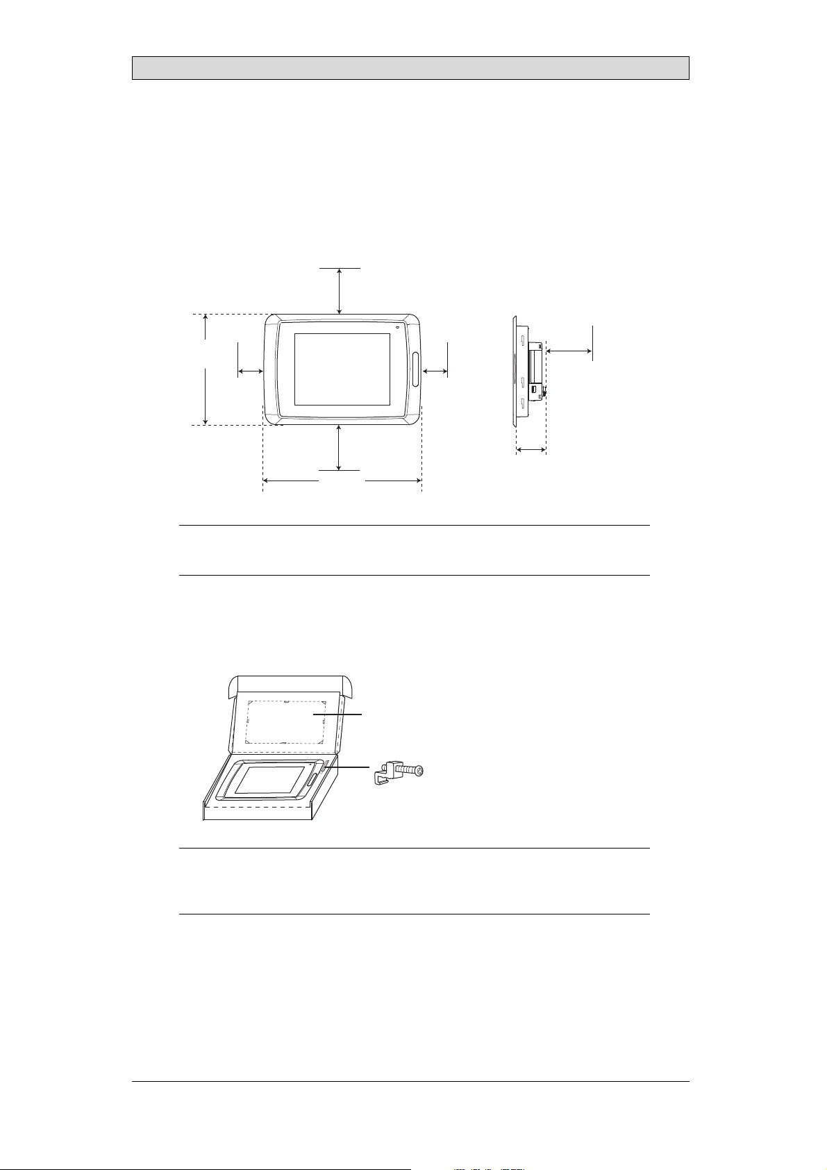
3.1 SpaceRequirements
• Installation plate thickness: 1.5 - 9.0 mm (0.06- 0.35 inch)
• Space requirementswhen installing EPC TA100AM:
100 mm
(4.0 inch)
228 mm
(8.98 inch)
50 mm
(2.0 inch)
100 mm
(4.0 inch)
302 mm
(11.89 inch)
50 mm
(2.0 inch)
58 mm
(2.28 inch)
Installation
100 mm
(4.0 inch)
Caution:
Theo penings ontheenclosurearefor airconvection. Donotcovertheseopenings.
3.2 InstallationProcess
1.
Unpackand check the delivery. If damage is found, notify the supplier.
Panel cut out 264.5 x 206.0 mm
(10.41 x 8.11 inch)
x 13
Note:
Placethe PanelPConastablesurfaceduring installation.
Droppingitorlettingitfallmaycausedamage.
BeijerElectronics, MAEN043
10
Page 11
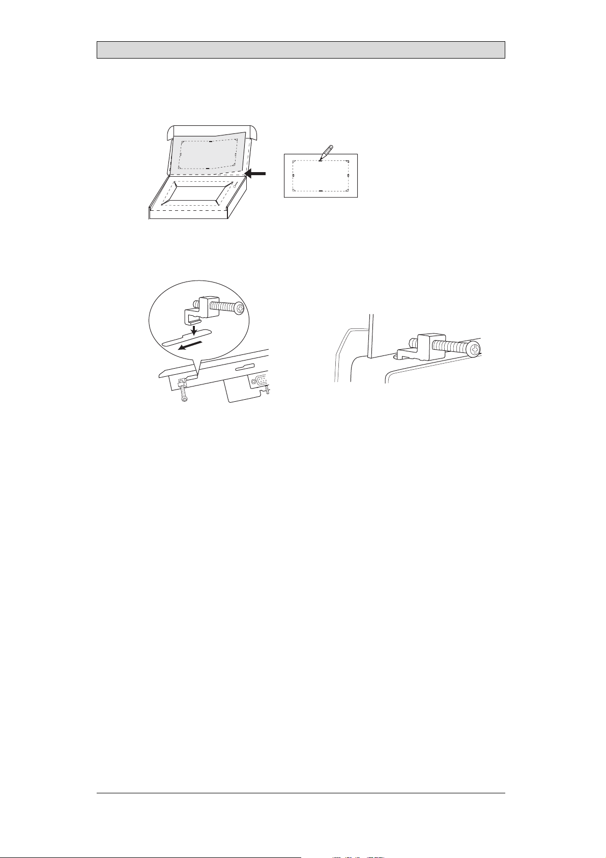
2.
Place the panel cut outwhere the Panel PC is to besituated, draw along the
outer sides of the holesand cut according to the markings.
3.
Secure the Panel PC in position, using all thefastening holes and the provided
brackets and screws:
x 13
Installation
0.5 - 1.0 Nm
BeijerElectronics, MAEN043
11
Page 12
Installation
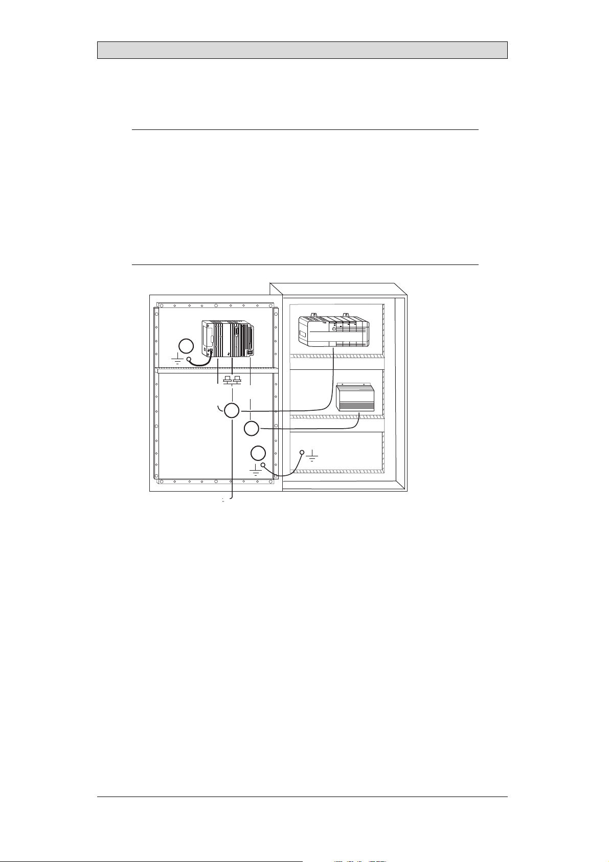
4.
Connect the cables in the specified order, according to the drawingand steps
below.
Caution:
• EnsurethatthePanelPCandthecontrollersystemhavethesameelectrical
grounding(referencevoltagelevel),otherwiseerrorsincommunicationmay
occur.
• ThePanelPCmustbebroughttoambienttemperaturebeforeitisstartedup. If
condensationforms,en surethatthePanelPCisdry beforeconnectingittothe
poweroutlet.
• Ensurethatthevoltageandpolarityofthepowersourceis correct.
• Useonlyshieldedcommunicationcables.
• Separatehighvoltagecablesfromsignalandsupplycables.
Power
CF CARD
B
1
Controller
RS422/RS485
RS232
24V DC
C
24V DC
D
A
Ethernet
– Connect cable A.
– Connect cable B, using an M5 screw and a grounding conductor (as short
as possible) with a cross-sectionof minimum 2.5 mm
– Connect cable C.
– Connect cable D.
5.
Carefully remove thelaminated film over thePanel PC display, to avoid static
2
.
electricity that could damage the panel.
3.2.1 OtherConnection
sandPeripherals
Cables, peripheral equipment and accessories must be suitable for theapplication
and its environment. Forfurther details or recommendations, please refer tothe
supplier.
BeijerElectronics, MAEN043
12
Page 13

Technical Data
4TechnicalData
Parameter EPCTA100 AM
Frontpanel,WxHxD 302x228x6mm
Mountingdepth 58m m (158mmincludingclearance)
Frontpanel seal IP66
Rear panel seal IP 20
Keyboard
material/Front
panel
Reverseside
material
Weight 2.1 kg
Serialport
RS422/RS485
SerialportRS232C 9-pinD-subcontact,malewith standardlockingscrews4-40
Ethernet 2x shieldedRJ45
USB Hosttype A(USB2.0),maxoutputcurrent500mA
Memoryslots 1x SDcard
Realtimeclock ±30PPM +errorbecauseofambienttemperature. Total
Power consumption
atrated voltage
Display TFT-LCD.800x600 pixels,64Kcolors.
Activeareaof
display,WxH
Fuse InternalDCfuse,3.15AT,5 x20mm
Powersupply +24VDC(20-30VDC).Powersupplyconnector.
Ambient
temperature
Storagetemperature -20°to +70°C
Relativehumidity 5- 85%non-condensed
Approvalsand
certifications
Touch screen: Polyesteronglass,1 millionfingertouch
operations. Overlay: AutotexF157orF207*.
Powder-coated aluminum
25-pinD-sub contact,chassis-mountedfemalewith
standardlockingscrews4-40UNC
UNC
maximumerror: 77seconds/monthat25°C.
Temperature coefficient: -0.034±0.006ppm/°C
Rechargeablebattery.
Normal: 0.5A
Maximum: 1.0A
CCFLbacklight lifetimeattheambienttemperatureof
+25°C:>50,000h.
211.2x 158.4mm
CE:Thepowersupplymustconformwiththerequirements
accordingtoIEC60950andIEC61558-2-4.
ULandcUL:Thepowersupplymustconformwiththe
requirementsfor classIIpowersupplies.
Verticalinstallation: 0°to+50°C
Horizontalinstallation: 0°to+40°C
Informationisavailableonthe website
www.beijerelectronics.com
2
*SeesectionChemicalResistance formoreinformation.
BeijerElectronics, MAEN043
13
Page 14

Chemical Resistance
5 ChemicalResistance
5.1 MetalCasing
The frame and casing material ispowder-coated aluminum. Thispowder paint
withstands exposure to thefollowing chemicals without visible change:
Aceticacid10% Phosphoricacid4%
Citricacid 10% Phosphoricacid10%
Diesel Seaw ater
Distilledwater Sodiumchloride2%
Edibleoil Sodiumchloride20%
Fueloil Sulphuricacid 20%
Hydrogenperoxide3% Tap water
The powder paintshows limited resistance to the f
ollowing chemicals at room
temperature:
Butanol Nitricacid3%
Hydrochloricacid5% Nitricacid 10%
Isopropylalcohol Phosphoricacid43%
Na-hypochlorite10% Turpentine
Note:
Ifexposuretoanyoftheabovechemicalsisdemanded,itisrecommendedtofirsttest
thechemical onan“invisible”spotof themetalcasing.
Thepowderpaintshowslittleornoresistancetothefollowingchemicalsatroom
temperature:
Aceticacid,conc. Methyl-ethylketone Toluene
Acetone Nitricacid 30% Trichlorethylene
Ammonia5% Phenol Xylene
Ammonia,conc. Sodiumhydroxide5% 97octanunleadedpetrol
Ethylacetate Sodiumhydroxide30% 98octanleadedpetrol
BeijerElectronics, MAEN043
14
Page 15

Chemical Resistance
5.2 TouchScreenandOverlay
5.2.1 AutotexF157/207
Autotex F157 or F207 coversthe overlay surrounding the touch screen.
SolventResistance
Autotex F157/F207 withstands exposure ofmore than 24 hours duration under
DIN42115Part2tothefollowingchemicalswithoutvisiblechange:
Acetonitrile DieselDowney/Lenor
Ajax/ Viminsolution EthanolPotassiumferricyanide
Alkalicarbonatesolution1Glycerine Potassiumhydroxide
Ammonia(<40%)
Aceticacid(<50%) Gumption
Arielpowderinsolution
1
Bleach
Castoroil Methanol Trichloroacetic acid
Causticsoda(<40%)
Cuttingoil Paraffinoil Windex
Cyclohexanol Persilpowderin solution1Wisk
Diacetonealcohol Petroleumspirit
1
Extremelyfaintglossingofthe texturewasnoted.
1
1
Glycol PureTurpentine
1
1
Hydrochloricacid(<36%) Sulfuricacid (<10%)
Linseedoil To ma to ketchup
Nitricacid (<10%) WhiteSpirit
1
Phosphoricacid(<30%)
(<30%)
SBP60/95
(<50%)
1
-
1
1
Autotex withstands DIN 42 115 Part 2 exposure of up to 1 hour duration to glacial
acetic acid without visiblechange.
Autotex is no
t resistant to high pressuresteam at over 100 °C or the following
chemicals:
Concentratedmineralacids Benzylalcohol
Concentratedcaustic solution Methylenechloride
OutdoorUse
In common with allpolyester based films Autotex F157/F207 is notsuitable for
use in conditions of longterm exposure to direct sunlight.
BeijerElectronics, MAEN043
15
Page 16

Chemical Resistance
5.2.2 TouchScreenSurface
Thetouchscreensurfaceonthepanelwithstandsexposuretothefollowing
solvents without visible change:
Solvents Time
Acetone 10minutes
Isopropanol 10minutes
Toluene 5 hours
5.2.3 AutoflexEB
It is recommendedto use the Autoflex EB touch display protection film, that can
be ordered from Beijer Electronics.
SolventResistance
Autoflex EB withstands exposureto the same chemicals as Autotex F157or F207
according to section AutotexF157/207.
OutdoorUse
In common with allpolyester based films Autotex EB is not suitable for usein
conditions of long term exposureto direct sunlight.
BeijerElectronics, MAEN043
16
Page 17

Hardware Replacement
6 HardwareReplacement
This section contains instructions on howto replace Panel PC hardware. Only
components included in the latest billof material and spare parts list are allowed.
See Available Spare Parts for EPC TA100 AM.
6.1 Cables
MostofthePanelPCsusethesametypeofflexcableconnectors.
connector flanges
Flex cable connector
To release the flex cables from the connector, gently push the
cable connector towards the flex cable.
Note:
Theconnectorsmustbeunlockedonbothsidesbeforeremovingthecable,otherwise
theflex cablem ay bedamaged.
two flanges on the
BeijerElectronics, MAEN043
17
Page 18

6.2 ReplacingtheRearCover
The following isneeded:
• Anewrearcover,seeAvailableSpare Parts forEPC TA100 AM
• AtorxT10screwdriver
Note:
MakesuretouseadequateESDprotection.
Follow the stepsbelow to replace therear cover:
1.
Power off the Panel PC.
2.
Remove the rear coverof the Panel PC by loosening the 4 torx screws.
4 x torx screws
Hardware Replacement
3.
Re-assemble withthe new rear cover in reverseorder.
BeijerElectronics, MAEN043
18
Page 19

Hardware Replacement
6.3 ReplacingtheDisplay/Display Cable
The following isneeded:
• A new display/display cable, see Available SpareParts for EPC TA100 AM
• AtorxT10screwdriver
Note:
MakesuretouseadequateESDprotection.
Followthe steps below toreplace the display/display cable:
1.
Power off the Panel PC.
2.
Followthe instructions under Replacing the Rear Cover to removethe rear
cover.
3.
Disconnect the two flex cables the flex cable and the LED cable from the
power cardand remove the twoplastic nuts that hold the power cardin place.
LED cable
plastic nut
flex cable
plastic nut
4.
Lift the power cardand gently remove the backlight cables and the display
cablefromtherearsideofthepowercard.
display cable
backlight cables
BeijerElectronics, MAEN043
19
Page 20

Hardware Replacement
5.
Remove the mounting plate(9 torx screws). Gently lift the mounting plate
with the display and powercard.
9 x torx screws
6.
Flip the mounting plate andu nscrew the 4 torx screws.
4 x torx screws
7.
Re-assemble thepanel in reverse order.
6.3.1 CalibratingtheTouchScreen
Followthe steps below to calibrate the touch screen:
A touch calibration toolis pre-installed in the EPC TA100 AM. Itcan be started
from the desktop icon orfrom the Start menu.
Note:
Touch calibrationhasto becommencedwithin10secondsfromwhen thetouchscreen
toolwasstarted.
BeijerElectronics, MAEN043
20
Page 21

Hardware Replacement
1.
Press the first calibration point until the Releasemessage appears.
Touch calibration point
If you releaset he calibration point too early,an error message is displayed.
2.
Touch the following nine touch calibration points as they appear onthe
screen, and release themas the Releasemessages appear.
When touch calibration has beenperformed succes
sfully, a confirmation is
displayed.
BeijerElectronics, MAEN043
21
Page 22

Hardware Replacement
6.4 ReplacingtheCompleteFront
The following isneeded:
• Anewfront,seeAvailable Spare Parts for EPC TA100 AM
• AtorxT10screwdriver
Note:
MakesuretouseadequateESDprotection.
Followthe steps below toreplace the complete front of theEPC TA100AM:
1.
Power off the Panel PC.
2.
Followthe steps 1-3 and 5 in the Replacing the Display/Display Cable instructions, but in step 3, onlydisconnect the flex cables and the LEDcable (do not
remove the power card).
3.
Attach the new front.
4.
Re-assemble the unit.
BeijerElectronics, MAEN043
22
Page 23

Hardware Replacement
6.5 ReplacingtheBacklight
Note:
Alllampsinthedisplaymustbereplacedatthe sametime.
The following isneeded:
• A new backlight, see Available Spare Parts for EPC TA100 AM
• AtorxT10screwdriver
Note:
MakesuretouseadequateESDprotection.
Followthe steps below to replace the battery of the EPC TA100 AM:
1.
First,follow the steps 1–5 insection Replacing the Rear Cover.
2.
Gently move the backlight diagonally in directionfrom the display center to
release the snap-in closure thatkeeps the backlight in place.
3.
Remove the backlight from the display.
backlight
backlight snap lock
4.
Insert the new backlight. Be careful not to pull thecables of the new backlight
when inserting it, since pulling thecables will damage the backlight.
5.
Re-assemble the complete Panel PC.
connectors
BeijerElectronics, MAEN043
23
Page 24

Hardware Replacement
6.6 AvailableSparePartsforEPCTA100 AM
Ordernumber Description
601009276 COMPLETEFRONT
Includingfrontcover,touchoverlay,gasketsand labels
601009027 DISPLAY
Includingframe andcable
601009050 BACKLIGHT
601009028 DISPLAYCABLE
321099040 POWERCONNECTOR
601009011 REARCOVER
601009003 CFCOVER
601009001 MOUNTINGBRACKETS
601009039 TOUCHPROTECTIONSHEET
601009308 FRONTLABEL
601009135 COMPLETEBOX
601009008 TESTPLUGETHERNET
EthernetRJ45 testconnector
601009006 TESTPLUGRS232
RS232test connector
601009007 TESTPLUGRS422/485
RS422/485testconnector
601009069 TESTPLUGUSBH
USBHosttestconnector
BeijerElectronics, MAEN043
24
Page 25

Additional InstallationTips
7 AdditionalInstallationTips
When experiencing communication problems in for example noisy environments
or when operating close to temperaturelimits, the following recommendations
are to be noticed.
7.1 GroundingthePanelPC
Mounting plate in the cabinet
Power supply
24 V DC
5350
Panel PC
1
Door
Ferrite core
6
3
2
5
4
The PanelPC’smounting clamps do not provide a securegrounding connection
between the PanelPC and the device cabinet, see 1 in drawing above.
1.
Connect a 2.5 mm
panel chassis, see 2in drawing abov
2.
Connect a 6 or 4 mm
2
wire between thePan
el PC’s quick-connect plinth andthe
e.
2
wire or grounding braidbetween the panel’schassis and
the closest grounding point on thedoor, see 3 in drawingabove.
3.
Connect a strong but short groundingbraid between the door and the device
cabinet,see 4 in drawing above.
4.
Twist the cables onto the 24V DC feed, see 5 in drawing above.
2 turns around theferrite core provide 4 times the suppressionof 1 turn.
3 turns around theferrite core provide 9 times the suppressionof 1 turn.
A ferrite core suppresses disturbances to the 24 V feed, see 6 in drawing above.
Note:
Theg rounding wiresshouldbeshortandtheconductorshould havealargearea.
Along,thingroundingwirehasa veryhighimpedance(resistance)athighfrequencies
andwill notguidedisturbancestotheground.
Multi-wireconductors arebetterthansinglewireconductorswiththesamearea.
Abraidedconductorwirewiththe sameareaisevenbetter. Thebestisashort,thick
groundingbraid.
BeijerElectronics, MAEN043
25
Page 26

Additional InstallationTips
7.2 EthernetConnectioninthePanel PC
Industrial Ethernet
RJ45
RJ45
RJ45
RJ45
Panel PC
RJ45
1
2
Panel PC
RJ45
Panel PC
RJ45
Panel PC
RJ45
5351
Shielded
0.1 uF
250 V
3
4
1-1
2-2
3-3
8-8
Short and
unshielded
5
In some industrial units forEthernet, the RJ45 contact’s shield is connected to the
chassis via a capacitor, see 1 in drawing above.
The PanelPC’sEthernet shield is directly co
nnected to the chassis, see 2in
drawing above.
1.
Check whether the other Ethernetun it has its shield directly grounded or
grounded via a capacitor.
Note:
Inmany cases,connectingtheshieldedEthernetcablingtothechassisatbothendsis
inappropriate. Humo r groundingloopscanoccur. Unshieldedcablingmayevenresult
infewer communicationerrors.
A good solution may be to usea shielded Ethernet cable, but toconnect the shield
at one end only.
One option is to breakthe shield, see 3 in drawing above.
A more elegant method isto expand the shielded Ethernet cabling with a piece of
unshielded Ethernetcable, see 4 in drawing above.
You can groundthe shield via an external 0.1 uF/250 V plastic capacitor, see 5 in
drawing above. This will connect the HF transientsto the ground.
BeijerElectronics, MAEN043
26
Page 27

Additional InstallationTips
7.3 ToAchieveBetterEMCProtection
• Initially,use the original cabling from Beijer Electronicsprimarily.
• Use shielded cables for RS232 communication.
• Use twisted pair and shielded cabling forRS422 and RS485.
• Use the cabling intended for the bus type; Ethernet, Profibus, CC-Link,
CAN, Device Netetc.
• Install and connect according to applicable specifications for the relevantbus
standard.
• Use shielded cabling for Ethernet,preferably with foil + braided shield.
• D-sub covers should be shielded, and the shield shouldbe connected to the
cover 360 °where the cable comes in.
• Connect the shield at both ends.
Shielded cable
0.1 uF/250 V
Ground plane 1 Ground plane 2
Ground plate Ground plate
Not same potential
in another building
5352
With longer distances, there is arisk that the ground potential may be different.
In that case, theshield should only be connected at one end. A good alternative
is to connect the other end of theshield to the ground via a 0.1 uF/250 V plastic
capacitor. Both endsare then connected to the ground in terms ofHF, but only
connected to the groundat one end in terms of LF, thus avoiding the 50Hz
grounding loops.
Metal cabinet Metal cabinet
Terminal or connector Terminal or connector
Cable clamp
in steel
Short distance
EMC cable gland Plastic cable gland
Shielded cable Shielded cable
1.
Usean EMC cable gland or regular plastic cable gland, remove theouter jacket
5353
and connect the shieldto the installation plate with a 360 ° metal cable clamp.
2.
Place the 24 VD C and communications cabling in one cable trunk/cable duct
and 230/380 V ACin another. If the cables need to becrossed, cross them at
90 ° only. Avoidcombining the cabling for stronger 24 V DC outputs with
the communication cabling.
Ferritecores that are snapped ontothe shielded cabling may removeminor
disturbances. Large ferrite pieces that are snappedonto unshielded cabling and
where the wiresgo 2-4 times around the cores are approximately5-25 times more
efficient.
BeijerElectronics, MAEN043
27
Page 28

Additional InstallationTips
7.4 AmbientTemperature
The maximum ambient temperaturefor the Panel PC is provided inthe
specifications. The ambient temperature refers to the temperature in the device
cabinet which cools the PanelPC’s electronics.
Top
50 °C inside
Panel
PC
30 °C outside
Middle
45 °C inside
Bottom
40 °C inside
Power
Power
Power
Axial fan
120 x 120 mm
Airflow
5354
Inmostcases,theambienttemperatureforthePanelPCissignificantlyhigher
than the device cabinet’s ambient temperature.
If the cabinetis tall and there are a numbero f heat
temperature at the topof the cabinet will be cons
theoretical temperature increasethat would b
sensitivetoheat. Thelifespanofanelectrol
° increase in temperature. A 15-20 ° temperat
-generating devices, the
iderably higher than the
e expected. All electronics are
ytic capacitor is cut in half with an 8-10
ure increaseresults in a quarter of the
lifespan etc.
Rittal has a good programfor estimating the anticipated average temperature in
the cabinet as wellas a large program for controlling the temperature in the device
cabinet.
An enamel-coated steel cabinethas
a radiant heat value of5.5 W/m
2
and degrees
C.
Installing a fan insidethe cabinet will even out the temperature, while movingair
provides considerablybetter cooling than still air. Asuitable fan is a 120 x 120 mm
axial fan, available in24 V DC, 115 and 230 V AC.
Installthefansothatitsit
Panel PC. If the fan is mount
temperaturewillbehighe
s in the cooler areaand will blow cold air againstt he
ed at the top andsucks air upwards, the fan’s ambient
r=shorterlifespan.
Agoodfanwithaball-bearingmountinghasanexpectedlifespanofatleast
40,000 hours (not aguaranteed lifespan) at 40 °C. This correspondsto at least 4
years of continuous use. If a thermostat is installed,the fan only needs to come
on when needed.
Large graphic termi
lighting is off. The
nals draw only one fifth of the currentwhen the background
loss effect drops from e.g. 25 W to only 5 W.
The PanelPC’sloss effect = supply voltage x current. Virtually no power goes to
external users and no loss effectsdue to inputs.
BeijerElectronics, MAEN043
28
Page 29

7.5 Safety
Most of the Panel PCs are fed with 24 V DC.
Power supply
1
2
3
230 V AC to 24 V DC
Power supply
230 V AC to 24 V DC
Power supply
230 V AC to 24 V DC
230 V AC
+24 V
0 V
4
+24 V
0 V
4
Distance?
+24 V
0 V
4
Panel PC
Panel PC
Panel PC
Small controller with expansion unit
COM1
COM100
Ch0
Ch1
Ch100
Ch101
5355
Additional InstallationTips
If you use apower supply that meets safety standardsandonlyfeedsthePanelPC,
there is noproblem. See 1in drawing above.
However,ifyouhavea24Vunitthatalsofeedsotherunits,thereisreasontobe
cautious, see 2 in drawing above. The Panel PCdoes not have insulation that
meets safety requirementsin the event of a potential short circuitbetween 230 V
AC and 24 V DC.It is assumed that the 24 V feed is secure, for example, SELV
according to EN60950 (protection against electric shock) and UL 950.
Example:
Hereisanexamplethatexplainswhyasecure24VDCfeedcanbe ruinedbymixing24
Vrelaycontactswith230VACrelaycontactsinasmallercontroller. Checkthatthe
“clearancesand creepagedistancesbetween24V DCand230VAC fulfillEN60950orUL
950”. Ifnot, inputaseparate 24VunitintothePanelP C.
If there is a substant
AC, it is OK to use the
ial distance between the relaycontacts for 24 V DC and 230 V
same 24 V devices forall feeds. See3 in drawing above.
Connect 0 V on the24 V feed to the ground,see 4 in drawing above. This offers
three advantages:
• Safety is increa
connection or s
• Tr an si e nt s o n t
• No risk that th
is not unusua
sed. The24Vfeedwillnotbeliveintheeventofafaulty
hortcircuitbetween0V(24V)and230Vphase.
he 24 V feed are connected to the ground.
e 24 V feed is ata high level in relationship to the ground. This
l since there is highstat ic electricity.
BeijerElectronics, MAEN043
29
Page 30

7.6 GalvanicIsolation
r
Additional InstallationTips
+24 V DC
DC/DC
galvanic isolation
Filter
0 V
1.5 m
Internal electronic
VCC
0 V (GND)
RS232RS422/485
USB
USB
DC/AC
Ethernet
CFL
5356
The PanelPC has galvanic isolation against the 24 VDC feed but no galvanic
isolation between the communication ports for RS232,RS422/485 and USB.
Only the Ethernetconnection has galvanic isolation.
Panel PC Modular controller Printe
RS422 RS232 USB
**
* *
Not same ground potential
* = Internal 0 V (GND) connection
When a PC is connected tothe panel, the panel’sinternal 0 V (G
*
Power CPU COM COM2
***
*
PCPC
5357
ND) will be
connected to the protective ground via the PC.
A number of USB devices canhave the shield connected together with the
protective ground. Here, the panel’s 0 V (GND) is connected to the protective
ground when, for example, aU SB memory stick, keyboard or similar device is
plugged in.
If a number of unitsare connected that have a 0 V a
these are connected to variousgrounding poin
problems. Grounding currents go through com
of the controller, and internally in th
e PanelPC, and can cause errors.
nd a ground connection, and
ts, there is asubstantial risk of
munication cables, the rearplate
Use external unitsto improve communication and achieve galvanic isolation.
Westermo has good industry-standard insulators that arealso insulated from the
24 V DC feed.
Note:
Itis veryimportanttomakesurethatthe24Vfeedin theexternalinsulationunitisnot
connectedtooneofthecommunication outlets. Ifitdoesnothave100%insulation
againstthe 24Vfeed,disturbancesandgroundingcurrentsfromthe0Vonthe24V
sidewilldisruptcommunication.
Usingthistypeofunitsolveso ne problembutcreates alargerproblem! A substandard
installationmayworknow,butproblemsmayarisewhenotherdevicesareconnected.
BeijerElectronics, MAEN043
30
Page 31

Additional InstallationTips
7.7 CableandBusTerminationRS485
• Use shieldedand twisted pair cable. The pair capacitance may not exceed 52.5
2
pF/m and areaat least 0.25 mm
(AWG 24), if you want to use themaximum
transfer distance and maximum transferspeed.
• 0 V, the reference voltage for communication should beincluded in
the cabling. With two-way communication use two pairs; onepair for
communication and one pair for 0V.
• The shield must be grounded at one end. The other end is usually grounded,
but with longer distances or whenthere is a difference in the ground potential,
theshieldshouldbeconnectedtothegroundvia0.1uF/250Vplastic
capacitor to preventground current in thebraided shield. A number of
manufacturers recommendthat the shield be grounded at each node. Various
manufacturers have different systemsfor bus termination. The RS485
standard does not describehow the “Fail Safe” function would be carried out,
justthatthesystemshouldbeabletohandletheerror.
Depending on the recipients’ design, the buswires may be on the same level or
require pull-up orpull-down to ensure that no faulty signals aredetected when the
bus is in restingmode (all transmitters are disconnected).
Inside Panel PC
+5 V
0 V
1 23
1 K
120 ohm 120 ohm
1 K
+5 V
(120 ohm)
14
1 K
2
15
6
19
1 K
7
8
0 V
0 V
4
55
17
50
Panel PC
RS422
1 2 3 4 5 6 7 8
CAB8CAB8 Bus
2
15
3
16
17
4
14
+5 V
VCC
8
0 V
7
0 V
VCC
1 K
120 ohm
1 K
RS485
1
2
3
4
5
6
7
8
Bus termination
Shield
0 V
0 V
5358
Some (older) operator panels hadpull-up and pull-down resistance except for
the actual bus termination at 120 ohm, similar toWestermo and Profibus. See 1
in drawing above.
The PanelPCs have another type of recipient, so-calledb uilt-in “Fail Safe”,where
simple bus termination resistance is sufficient. See 2 in drawing above.
If other nodes on theRS485 network require pull-up andpull-down and the Panel
PC is at one endof the loop, one of the followingprocedures can be carried out:
• Connect two 1k/0.25 W resistors in the25-pole D-sub contact. See 3 in
drawing above. Set jumper pins6-19.
• Use CAB8. It offers the option of bus terminationwith pull-up/-down. It
isalsoeasytoconnectthebuscableviathescrewterminalblock. See4in
drawing above.
BeijerElectronics, MAEN043
31
Page 32

Fault T racing
8FaultTracing
This section includes differentfault scenarios and steps to follow to trace the fault.
TheEPCTA100AMisnotworkingproperly,andthe
powerLEDisoff
1.
Isthepowervoltagecorrect?
2.
Does the powersupply deliver enough current?
3.
Check the fuse.
4.
Check the power card.
5.
Is thepower card correctly mounted?
TheEPCTA100AMisnotcommunicating
1.
Check the communication cable between the units.
2.
Check the communication ports onthe CPU board.
TheEPCTA100AMisworkingbutthebacklightisoff
1.
Check the backlight dimming.
2.
Check that the backlight is connected to the power card.
3.
Replace the backlight accordingto the Replacing the Backlight section.
4.
Check the DC/AC on the powercard.
TheEPCTA100AMisnotworking,thebacklightisoff
butthepower LEDison
1.
Check the backlight dimming.
2.
Check the CPU boardfor burned components.
3.
Download new firmwareto the Panel PC.
TheEPCTA100AMdoesnotincludethelatest
software
1.
Followthe instructions in section Updateor Customize Software.
BeijerElectronics, MAEN043
32
Page 33

Thetouchscreenismalfunctioningorisnot
respondingatall
1.
Re-calibrate the touch screen according tothe Calibrating the Touch Screen sec-
tion.
2.
Check that the flex cable is correctly fitted.
3.
Replace the display of the Panel PC according to the
Replacing theDisplay/Display Cable section.
4.
Check the touch interface on the power card.
Linesindisplay havewrongcolororthedisplay
pictureisshifted
1.
Check if the display has a wide vertical or horizontal areaacross the
display. It should be at least 2-3 cmwide with a grey or black color. See
Replacing theDisplay/Display Cable for instructions on how to correct this.
2.
Make sure the display cable is correctlyfitted.
3.
Make surethe display cable is not folded or damaged in anyway. Replace the
display cable accordingto the Replacing the Display/DisplayCable section.
Fault T racing
BeijerElectronics, MAEN043
33
Page 34

9Software
This chapter describes how to maintain andupdate the operating system in the
EPC TA100 AM, and instructions about howto recover the operating system.
9.1 GeneralInformationabout Software
The EPC TA100 AM is delivered with an image (operating system) pre-storedin
the NandFlash memory.
9.1.1 SoftwareProducts
The following softwareproduct is used:
• Operating System: Windows® XP Embedded SP3
Software
BeijerElectronics, MAEN043
34
Page 35

Software
9.2 UpdateorCustomizeSoftware
A customized operatingsystem image can be developed with theneeds of the
customer. Inthis case, please contact Beijer Electronics sales office for detailed
information.
9.2.1 BackupandRecovery
It isimportant to generate a backupimage of the operating system. In case of
emergency, a recoverycan be done in minutes using a backupimage. Several
programs on the market aresuitable for this.
A bootable device (such as aCD drive or USB Stick with a backupand recovery
program) as well a keyboardand mouse can easily be connected using a USB hub.
The default BIOS setting is set to boot automatically first from aUSB device.
RecoveringtheSystemUsingaUSBMe moryStickwith
aBeijerElectronics-PreparedBackupImage
Requirements:
• Acronis True Image Version 11 installed on the desktop PC
Performthe following steps to recover the system:
1.
Connect an empty USB memory stick (4 GB)to your PC. 8. . 9.
2.
Start Acronisand load the image (***.tib) to the USB stick.
3.
Connect the USB stick to the Panel PC and switch the powe
Windows XP Embedded is now loading from USB Device.
On the WindowsXP Embedded desktop you will find:
a) A program named EasyImage(in the Utility folder)
b) Animage (in the Image folder) to restore the
Windows XP Embedded
4.
Start the EasyImageprogram, select the Image file and start to restore the
internal NandFlash.
After finishing restoring, you can shutdownthe Panel PC via the Start menu.
5.
Disconnect the USB stickand power on the PanelPC.
Windows XP Embeddedw ill now be loaded from the internal flash.
internal NandFlash with
ron.
BeijerElectronics, MAEN043
35
Page 36

Environmental Aspects
10 EnvironmentalAspects
This chapter includes information about theenvironmental impact of the EPC
TA100 AM. More information can befound on the manufacturer’s web site.
10.1 GeneralEnvironmentalAspects
The manufacturer’s activities meet internal requirementsas well as those of the
SS-EN ISO 9001:2000and SS-EN ISO 14001:2004 international standards.
10.2 EnvironmentalImpactofthePanel PCs
10.2.1 MechanicalComponents
The aluminum and stainless steel usedin the mechanical components are judged
to be non-environmentally hazardous. The expanded rubber packing for the front
and the expanded polyethylene packing forthe display contain an adhesive that is
not classified as environmentally hazardous.
Screws may have undergone thefollowing surface treatments: Bright
nickel-plating or bright zinc-plating. Themembranekeyboardismadeof
polyester with silver wiring. On some models the keyboard contains LEDs.
Display frames andCF covers are made of halogen-free plastic, PC/ABS.
10.2.2 Electronics
CircuitBoard
Note:
AllPanelPCs areRoHScompliant.
The electronics are complex and almost all elements of the periodic table are
represented.
Display
There is a separatecircuit board for the display. The liquid crystals in the display
are cyclohexanecompounds. The fluorescent tubecontains mercury and lead
solder.
Batteries
The PanelPC
environme
contains a button cell lithium battery. The battery is not classified as
ntally hazardous bythe Swedish Battery Ordinance(1997:645).
BeijerElectronics, MAEN043
36
Page 37

Environmental Aspects
10.3 Recycling
The PanelPCs consist largely of aluminum. It is a greatadvantage in terms of both
resources and the environment ifit can be recycled. Make sure that Panel PCs
taken out of service are sent to facilitiesfor electronic scrap.
The manufacturer’s electronic waste is recycled by Stena Technoworld AB.
Aluminum front/rearcasings and other coverscan be removedand recycled.
Plastic display frames and CF coversmust be recycled as hard plastic. The circuit
board contains many valuablemetals and should therefore be recycled.
Remove the lithium battery. Electrolytic capacitors and displays are currently not
classified as hazardouswaste, but may be harmful to health and the environment.
The electrolytic capacitors should be handled asper Handbook 2001:7 (NFS)
and displays as perNFS 2001:8.
Thefluorescenttubemustbehandledashazardouswaste.
The packaging ismade from wood fiber and shouldberecycled. Thelargeprinted
label on the front, however, must firstbe removed as it is made of PVCvinyl. The
label and theplastic bag for the brackets are recycledas soft plastic.
The manufacturer is amember of the REPAregister. The protective film onthe
front is recycled assoft plastic. When the PanelPC is no longer useful it can be
returned to the manufacturer for environmentally responsiblerecycling. Contact
the company for further information.
10.4 EnvironmentalImpactReport
A PanelPC impacts the environment through its function,i.e., controlling
industrial equipment. The energy and the scrapped parts that can be saved
with efficient management mean thatthe PanelPC contributes to reduced
environmental impact.
Listed below areexamples of how you can reduce environmentalimpact during
Panel PC use.
• Switch thesystem off when not in use.
• Use g reen electricity.
• Use energy-savingoptions, e.g., turn off the backlight to both save energy and
reduce wearon the fluorescent tube.
• If possible, reduce the backlight brightness to reduceenergy consumption
and increase fluorescenttube service life.
Supplyt he Panel PC with 24 V DC.I
increases. Ensure that the Pan
environmentally responsible
manner.
f the input voltageis lower,the loss effect
el PC, battery, and packaging are recycledin an
BeijerElectronics, MAEN043
37
Page 38

Headoffice
BeijerElectronicsAB
Box426
20124Malmö,Swed
en
www.beijerelectronics.com/+4640358600
 Loading...