

Page 1
Users Manual
Version 1.2 July 2002
ENGLISH
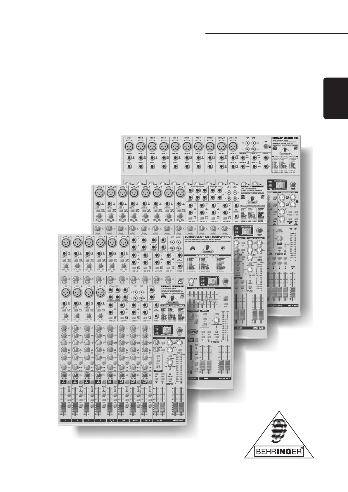
UB1622FX-PRO UB1832FX-PRO UB2222FX-PRO UB2442FX-PRO
®
EURORACK
www.behringer.com
Page 2
EURORACK UB1622FX-PRO/UB1832FX-PRO/UB2222FX-PRO/UB2442FX-PRO
SAFETY INSTRUCTIONS
CAUTION: To reduce the risk of electric shock, do not remove
the cover (or back). No user serviceable parts
inside; refer servicing to qualified personnel.
WARNING: To reduce the risk of fire or electric shock, do not
expose this device to rain and moisture.
This symbol, wherever it appears, alerts you to the
presence of uninsulated dangerous voltage inside
the enclosurevoltage that may be sufficient to
constitute a risk of shock.
This symbol, wherever it appears, alerts you to
important operating and maintenance instructions
in the accompanying literature. Please read the
manual.
DETAILED SAFETY INSTRUCTIONS:
All the safety and operation instructions should be read before
the device is operated.
Retain Instructions:
The safety and operating instructions should be retained for
future reference.
Heed Warnings:
All warnings on the device and in the operating instructions
should be adhered to.
Follow instructions:
All operation and user instructions should be followed.
Water and Moisture:
The device should not be used near water (e.g. near a bathtub,
washbowl, kitchen sink, laundry tub, in a wet basement, near a
swimming pool etc.).
Ventilation:
The device should be situated so that its location or position
does not interfere with its proper ventilation. For example, the
device should not be placed on a bed, sofa, rug, or similar surface
that may block the ventilation openings, or used in a built-in
installation, such as a bookcase or cabinet that may impede the
flow of air through the ventilation openings.
Heat:
The device should be situated away from heat sources such
as radiators, heat registers, stoves, or other devices (including
amplifiers) that produce heat.
Power Source:
The device should only be connected to a power supply of the
type described in the operating instructions or on the device.
Grounding or Polarization:
This device must be grounded.
Power Cords:
Power cords should be routed so that they are not likely to be
walked on or pinched by items placed upon or against them,
paying particular attention to cords and plugs, sockets, outlets
and the point where they exit from the device.
Cleaning:
The device should be cleaned only as recommended by the
manufacturer.
Non-use Periods:
The power cord of the device should be unplugged from the
outlet when left unused for a long period of time.
Debris and Liquid Entry:
Debris and/or liquids should not be allowed to enter the
enclosure through openings.
Damage Requiring Service:
The device should be serviced by qualified service personnel
when:
s The power cord or the plug has been damaged; or
s Debris or liquid has entered the device; or
s The device has been exposed to rain; or
s The device does not appear to operate normally or exhibits
a pronounced change in performance; or
s The device has been dropped, or the enclosure damaged.
Servicing:
The user should not attempt to service the device beyond that
which is described in the operating instructions. All other
servicing should be referred to qualified service personnel.
2
Page 3

EURORACK UB1622FX-PRO/UB1832FX-PRO/UB2222FX-PRO/UB2442FX-PRO
TABLE OF CONTENTS
1. INTRODUCTION ......................................................................................................... 4
1.1 General mixing console functions .................................................................................................................... 4
1.2 The users manual ........................................................................................................................................... 5
1.3 Before you get started ....................................................................................................................................... 5
1.3.1 Shipment ................................................................................................................................................ 5
1.3.2 Initial operation ....................................................................................................................................... 5
1.3.3 Warranty ................................................................................................................................................. 5
2. CONTROL ELEMENTS AND CONNECTORS .......................................................... 5
2.1 Mono channels ................................................................................................................................................. 5
2.1.1 Microphone and line inputs ................................................................................................................... 5
2.1.2 Equalizer................................................................................................................................................. 6
2.1.3 Aux sends ............................................................................................................................................... 6
2.1.4 Routing switch, PAN, SOLO and channel fader ..................................................................................... 6
2.2 Stereo channels ................................................................................................................................................ 7
2.2.1 Channel inputs ....................................................................................................................................... 7
2.2.2 Equalizer stereo channels ..................................................................................................................... 7
2.2.3 Aux sends stereo channels ................................................................................................................... 7
2.2.4 Routing switch, solo and channel fader ................................................................................................ 7
2.3 Interface panel and main section ..................................................................................................................... 7
2.3.1 MON control, aux sends 1, 2 and 3 (FX) ................................................................................................ 7
2.3.2 Aux send jacks ....................................................................................................................................... 8
2.3.3 Stereo aux return connectors ................................................................................................................. 8
2.3.4 The monitor section of the UB1832FX-PRO .......................................................................................... 8
2.3.5 Stereo aux return control ........................................................................................................................ 9
2.3.6 Supplement to UB1832FX-PRO ............................................................................................................ 9
2.3.7 Surround function (UB1832FX-PRO only) ........................................................................................... 10
2.3.8 Tape input/tape output .......................................................................................................................... 10
2.3.9 Lamp socket (UB2442FX-PRO only) ................................................................................................... 10
2.3.10 Level meter and monitoring ................................................................................................................. 10
2.3.11 Subgroups and main mix fader ........................................................................................................... 11
3. GRAPHIC 9-BAND EQUALIZER (UB1832FX-PRO only) ....................................... 11
4. DIGITAL EFFECTS PROCESSOR ........................................................................... 12
5. REAR PANEL CONNECTORS ................................................................................ 12
5.1 Main mix outputs, insert points and control room outputs ............................................................................. 12
5.2 Subgroup outputs ........................................................................................................................................... 12
5.3 Inserts ............................................................................................................................................................. 13
5.4 Direct outputs (UB2442FX-PRO only) ............................................................................................................ 13
5.5 Voltage supply, phantom power supply and fuse ........................................................................................... 13
6. INSTALLATION ......................................................................................................... 14
6.1 Rack mounting ................................................................................................................................................ 14
6.2 Cable connections .......................................................................................................................................... 14
6.2.1 Audio connections ................................................................................................................................ 14
7. SPECIFICATIONS .................................................................................................... 15
8. WARRANTY.............................................................................................................. 16
3
Page 4
EURORACK UB1622FX-PRO/UB1832FX-PRO/UB2222FX-PRO/UB2442FX-PRO
FOREWORD
Dear Customer,
Im sure youre one of
those people who have
devoted themselves body
and soul to your chosen
area and no doubt this has
transformed you into an
expert in your field!
Well, for over 30 years,
my passion has been
music and electronics.
This not only led me to
establish BEHRINGER,
but also enabled me to
convey and share my
enthusiasm with my
employees.
During all the years Ive
been involved with studio
technology and end users,
I have developed a feel for the things that really count, such as
sound quality, reliability and ease of use. Whats more, I have always
had the desire to push the boundaries of technical possibilities to the
extreme.
It was precisely this motivation that prompted me to start work
on a new series of mixing consoles. Since our EURORACKs had
already set new standards world-wide, I knew the development
objectives behind the products bearing my initials had to be
especially ambitious.
Thus, the concept and design of the new UB mixing consoles
bear my signature. The design work, the entire circuit diagram
and PCB development, and even the mechanical concepts are
my own work. I carefully selected each individual component
with the aim of pushing the mixing consoles analog and digital
technologies to their limits.
My vision was to enable you, the user, to give free rein to your
true potential and creativity. The result is incredibly powerful mixing
consoles that offer intuitive operation. They cannot fail to impress
with their extremely flexible routing possibilities plus fantastic wealth
of functions. Innovative technologies, such as the completely new
IMP Invisible Mic Preamps, guarantee optimum sound quality.
And extraordinarily high-quality components provide unrivalled
reliability, even under extreme loads.
Your new UB mixing console is of high quality yet is simple to
use; youll soon appreciate that I, both personally and in my
capacity as musician and sound engineer, put you, the end user,
first and that these products were only possible because of the
passion and the attention to detail that went into them.
Thank you for the confidence you have placed in us by
purchasing the UB mixing console. I should also like to thank all
those who, with their personal commitment and passion, have
helped me realize this impressive series of mixing consoles.
Kindest regards,
Uli Behringer
1. INTRODUCTION
Congratulations! In purchasing the BEHRINGER EURORACK
you have acquired a mixer whose small size belies its incredible
versatility and audio performance.
The BEHRINGER EURORACK mixing console offers you
premium-quality microphone preamplifiers with optional phantom
power supply, balanced line inputs and the ability to connect
external effects devices. Because of its extensive and carefully
thought-out routing possibilities, your EURORACK lends itself
equally to both live and studio use.
IMP INVISIBLE MIC PREAMP
The microphone channels are fitted with BEHRINGERs brand
new high-end IMP INVISIBLE MIC PREAMPs that boast the
following features:
s 130 dB dynamic range for an incredible amount of headroom
s A bandwidth ranging from below 10 Hz to over 200 kHz for
crystal-clear reproduction of even the finest nuances
s The extremely low-noise and distortion-free circuitry gua-
rantees absolutely natural and transparent signal reproduction
s They are perfectly matched to every conceivable micro-
phone with up to 60 dB gain and +48 volt phantom power
supply
s They enable full utilisation of the greatly extended dynamic
range of your 24-bit/192 kHz HD recorder, thereby maintaining optimal audio quality
In addition, your BEHRINGER EURORACK offers an effects
processor equipped with 24-bit A/D and D/A converters. The
processor is fitted with the effect algorithms from our tried and
tested 19" multi-effects device, the VIRTUALIZER PRO DSP2024P.
99 presets are available providing first-class room simulations,
delay and modulation effects, as well as compression, tube
distortion and many other effects, all with stunning audio quality.
The mixing consoles of the PRO series feature a state-of-the-art
integrated switch-mode power supply. One of the great advantages
is that (compared to conventional circuits) a switch-mode power
supply adapts to mains voltages between 100 and 240 volts
automatically. Furthermore, due to its much greater efficiency, it
consumes much less energy than a conventional power supply
unit.
CAUTION!
+ We should like to draw your attention to the fact that
extreme volumes may damage your hearing and/or
your headphones or loudspeakers. Turn the MAIN
MIX faders and phones control in the main section
fully down before you switch on the unit. Always be
careful to set the appropriate volume.
1.1 General mixing console functions
A mixing console fulfils three main functions:
s Signal processing: Preamplification, level adjustment,
frequency response correction, mixing of effects.
s Signal distribution: Collection of the signals on the
aux sends for effects processing and the monitor mix,
distribution on several recording tracks as well as power
amp(s), control room and 2-track outputs.
s Mix: Setting the volume level/frequency distribution/
positioning of the individual signals in the stereo image,
level control of the total mix to match the recording devices/
crossover/power amplifier. All other mixer functions come
under this main discipline.
The control surface of BEHRINGER mixing consoles is optimized in such a way that these functions become easy to fulfil
while the signal path remains simple to follow.
4
1. INTRODUCTION
Page 5
EURORACK UB1622FX-PRO/UB1832FX-PRO/UB2222FX-PRO/UB2442FX-PRO
1.2 The users manual
The users manual is designed to give you both an overview of
the controls, as well as detailed information on how to use them.
In order to help you understand the links between the controls,
we have arranged them in groups according to their function. If
you need to know more about specific issues, please visit our
website at http://www.behringer.com, where youll find
explanations of e.g. effects and dynamics applications.
+ The block diagram supplied with the mixing console
gives you an overview of the connections between
the inputs and outputs, as well as the associated
switches and controls.
For the moment, just try and trace the signal path from the
microphone input to the aux send 1 connector. Dont be put off
by the huge range of possibilities; its easier than you think! If you
look at the overview of the controls at the same time, youll be
able to quickly familiarize yourself with your mixing console and
youll soon be making the most of all its many possibilities.
1.3 Before you get started
1.3.1 Shipment
Your mixing console was carefully packed in the factory to
guarantee safe transport. Nevertheless, we recommend that
you carefully examine the packaging and its contents for any
signs of physical damage, which may have occurred during
transit.
2. CONTROL ELEMENTS AND
CONNECTORS
This chapter describes the various control elements of your
mixing console. All controls, switches and connectors will be
discussed in detail.
2.1 Mono channels
2.1.1 Microphone and line inputs
+ If the unit is damaged, please do NOT return it to us,
but notify your dealer and the shipping company
immediately, otherwise claims for damage or
replacement may not be granted.
1.3.2 Initial operation
Be sure that there is enough space around the unit for cooling
purposes and to avoid over-heating please do not place your
mixing console on high-temperature devices such as radiators
or power amps. The console is connected to the mains via the
supplied cable. The console meets the required safety standards.
Blown fuses must only be replaced by fuses of the same type
and rating.
+ Please note that all units must be properly
grounded. For your own safety, you should never
remove any ground connectors from electrical
devices or power cables, or render them inoperative.
+ Please ensure that only qualified people install and
operate the mixing console. During installation and
operation, the user must have sufficient electrical
contact to earth, otherwise electrostatic discharges
might affect the operation of the unit.
1.3.3 Warranty
Please take time to fill out and return the warranty card within
14 days after the date of purchase, so as to be entitled to benefit
from our extended warranty. Alternatively, you can use our
online registration option available on the world wide web
(www.behringer.com). You will find the serial number on the
rear of your mixing console.
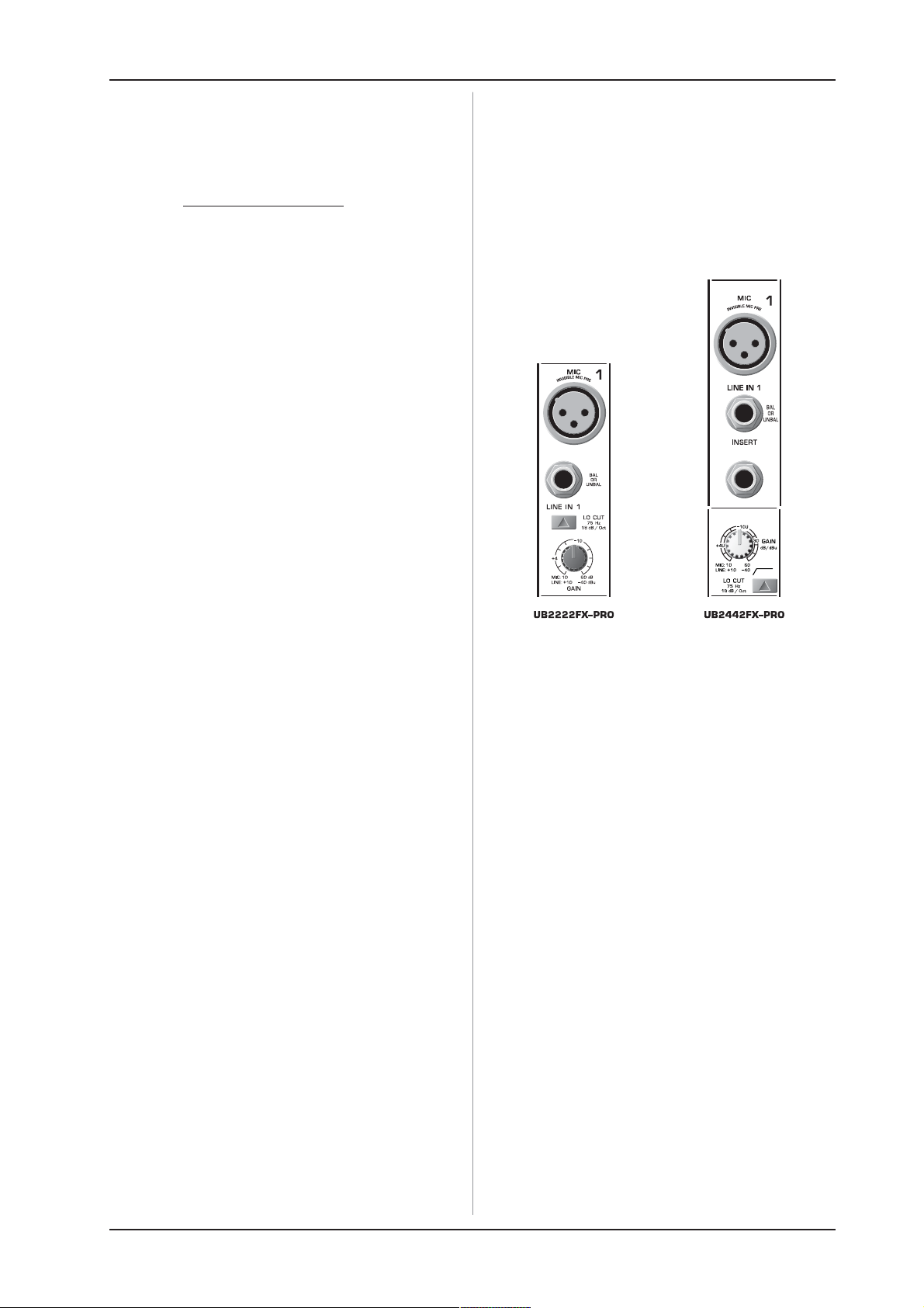
Fig. 2.1: Connectors and controls of mic/line inputs
MIC
Each mono input channel offers a balanced microphone input
via XLR as well as switchable phantom power (+48 volt) for
powering condenser microphones.
+ Please mute your monitor system before you
switch on phantom power. Otherwise potentially
damaging thumps will be sent to your speakers.
Please also note the instructions in chapter 5.5
Voltage supply, phantom power and fuse.
LINE IN
Each mono input also has a balanced line input on a 1/4" jack.
You can also connect unbalanced devices using mono jacks to
these inputs.
+ Please remember that you can use either the
microphone input or the line input of a channel, but
not both at the same time!
INSERT
Insert points enable the processing of a signal with dynamic
processors or equalizers. They are sourced pre-fader, pre-EQ
and pre-aux send. Detailed information on using insert points
can be found in chapter 5.3.
+ Unlike the UB2442FX-PRO, the UB1622FX-PRO,
UB1832FX-PRO and UB2222FX-PRO have their insert
points located on the rear of the console.
GAIN
Use the GAIN control to adjust the input gain. This control
should always be turned right down whenever you connect or
disconnect a source on one of the inputs. The GAIN control
governs both the microphone and the LINE input level. The MIC
graduation indicates the gain range (10 to 60 dB), while LINE
shows the input level (+10 to -40 dBu), ensuring optimum level
matching.
2. CONTROL ELEMENTS AND CONNECTORS
5
Page 6

EURORACK UB1622FX-PRO/UB1832FX-PRO/UB2222FX-PRO/UB2442FX-PRO
The two most common operating levels (+4 dBu and -10 dBV)
are highlighted for quick and accurate level setting.
LO CUT
Additionally, the mono channels of the mixing consoles have a
high-slope LO CUT filter for eliminating unwanted, low-frequency
signal components (75 Hz, 18 dB/octave).
2.1.2 Equalizer
All mono input channels have a 3-band equalizer with semiparametric mid bands. All bands provide boost or cut of up to
15 dB. In the central position, the equalizer is off (flat).
Fig. 2.2: Equalizer of the input channels
The upper (HI) and the lower (LO) bands are shelving filters
that increase or decrease all frequencies above or below their
cut-off frequency. The cut-off frequencies of the upper and
lower bands are 12 kHz and 80Hz respectively. For the mid
range, the console features a semi-parametric equalizer with a
filter quality (Q) of 1 octave, tunable from 100 Hz to 8 kHz. Use
the MID control to set the amount of boost or cut, and the FREQ
control to determine the central frequency.
PRE
When the PRE switch is pressed down, the associated aux
send is taken pre-fader.
AUX (FX)
The aux send marked FX offers a direct route to the built-in
effects processor and is therefore post-fader and post-mute.
Please refer to chapter 4 DIGITAL EFFECTS PROCESSOR for
detailed information.
+ If you are using the built-in effects processor, make
sure that STEREO AUX RETURN 3 has nothing plugged
into it (UB2442FX-PRO and UB2222FX-PRO), otherwise
the internal effects return will be muted. This is
not relevant if you use the FX OUT jack to drive an
external effects device.
+ UB1622FX-PRO and UB1832FX-PRO: On these
consoles, the above note refers to the STEREO AUX
RETURN 2 jacks as these models do not have a
dedicated effect output.
2.1.4 Routing switch, PAN, SOLO and channel fader
2.1.3 Aux sends
Fig. 2.3: The AUX SEND controls in the channel strips
AUX sends source their signals via a control from one or more
channels and sum these signals to a so-called bus. This bus
signal is sent to an aux send connector and then routed, for
example, to an active monitor speaker or external effects device.
In the latter case, the effects return can then be brought back
into the console via the aux return connectors.
All aux sends are mono, post-EQ and offer up to +15 dB gain.
Pre-fader/post-fader
When using effects on a channel signal, it is usual to have the
aux send post fader so that the balance between effect and dry
signal stays constant even when the channel fader is altered. If
this were not the case, the effects signal of the channel would
remain audible even when the channel fader is turned to zero.
For monitoring, the aux sends are generally pre-fader, i.e. they
operate independently of the position of the channel fader.
Fig. 2.4: The panorama and routing controls
and the channel fader
PA N
The PAN control determines the position of the channel signal
within the stereo image. When working with subgroups, you
can use the PAN control to assign the signal to just one output,
which gives you additional flexibility in recording situations. For
example, when routing to subgroups 3 and 4, panning hard left
will route the signal to group output 3 only, and panning hard
right will route to group output 4 only.
MUTE
The MUTE switch breaks the signal path pre-channel fader,
hence muting that channel in the main mix. The aux sends which
are set to post-fader are likewise muted for that channel, while
the pre-fader monitor paths remain active irrespective of whether
the channel is muted or not.
MUTE LED
The MUTE LED indicates a muted channel.
PEAK LED
The PEAK LED lights up when the input signal is driven too
high. If this happens, back off the GAIN control and, if necessary,
check the setting of the channel EQ.
6
2. CONTROL ELEMENTS AND CONNECTORS
Page 7

EURORACK UB1622FX-PRO/UB1832FX-PRO/UB2222FX-PRO/UB2442FX-PRO
SOLO
The SOLO switch is used to route the channel signal to the
solo bus (Solo In Place) or to the PFL bus (Pre Fader Listen). This
enables you to listen to a channel signal without affecting the
main output signal. The signal you hear is taken either before the
pan control (PFL, mono) or after the pan and channel fader
(Solo, stereo) (cf. chap. 2.3.10 Level meters and monitoring).
SUB (1-2 and 3-4)
The SUB switch routes the signal to the corresponding
subgroups. The UB2442FX-PRO has 4 subgroups (1-2 and 3-4).
MAIN
The MAIN switch routes the signal to the main mix bus.
The channel fader determines the channels volume in the
main mix (or submix).
2.2 Stereo channels
2.2.1 Channel inputs
The Hi and Lo controls have the same characteristics as the
EQ in the mono channels. Both mid range bands are of the peak
filter type. A stereo EQ is superior to two mono EQs on a stereo
signal as two separate EQs will usually result in a discrepancy
between left and right channels.
2.2.3 Aux sends stereo channels
In principle, the aux sends of the stereo channels function the
same way as those of the mono channels. As the aux sends are
mono, the send from a stereo channel is first summed to mono
before it reaches the aux bus.
2.2.4 Routing switch, solo and channel fader
Fig. 2.6: Balance control and mute switch
BAL
The BAL(ANCE) control has a similar function to the PAN control
in the mono channels.
The balance control determines the levels of the left and right
input signals relative to each other before both signals are routed
to the left/right main mix bus (or odd/even subgroup).
The remaining control elements in the stereo channels perform
the same functions as their counterparts in the mono channels
(MUTE switch, MUTE and PEAK LEDs, SOLO switch, SUB and
MAIN switches and channel fader).
Fig. 2.5: The various stereo channel inputs
Each stereo channel has two balanced line level inputs on
jacks for left and right channels. Channels 9/10 and 11/12 on the
UB2442FX-PRO feature an additional XLR microphone jack with
phantom power. If only the left jack (marked L) is used, the
channel operates in mono. The stereo channels are designed to
handle typical line level signals, and, depending on model, have
a level switch (+4 dBu or -10 dBV) and/or a line gain control.
Both jack inputs will also accept unbalanced connectors.
LO CUT and MIC GAIN
These two control elements operate on the XLR connectors of
the UB2442FX-PRO, and are used to filter out frequencies below
75 Hz (LO CUT) and to adjust microphone levels (MIC GAIN).
LINE GAIN
Use this control to adjust the line signal levels on channels
13-16 (UB2442FX-PRO only).
LEVEL
For level matching, the stereo inputs on the UB1622FX-PRO,
UB1832FX-PRO and UB2222FX-PRO have a LEVEL switch to
select between +4dBu and -10dBV. At -10dBV (homerecording
level), the input is more sensitive than at +4dBu (studio level).
2.3 Interface panel and main section
Where it was useful to trace the signal flow from top to bottom
in order to gain an understanding of the channel strips, we now
look at the mixing console from left to right. The signals are, so to
speak, collected from the same point on each of the channel
strips and then routed to the main section all together.
2.3.1 MON control, aux sends 1, 2 and 3 (FX)
Turning up the AUX 1 control in a channel routes the signal to
the aux send bus 1.
+ As the UB1832FX-PRO is equipped with an additional
monitor path, its first aux control in the channel
strips is named MON. The console also has a
dedicated MONITOR master fader for this aux path.
2.2.2 Equalizer stereo channels
The stereo channels contain a stereo EQ section. The cut-off
frequencies of the high and low bands are 12 kHz and 80 Hz
respectively, while the center frequencies of the high-mid and
low-mid bands are 3 kHz and 500 Hz respectively.
2. CONTROL ELEMENTS AND CONNECTORS
Fig. 2.7: The AUX SEND controls of the main section
7
Page 8

EURORACK UB1622FX-PRO/UB1832FX-PRO/UB2222FX-PRO/UB2442FX-PRO
AUX SEND 1, 2 and 4
The AUX SEND 1 control governs the master send level of the
mix created by the individual channel AUX 1 sends.
Likewise, the AUX SEND 2 contol is the master control for the
aux 2 bus, and AUX SEND 4 controls the AUX 4 bus.
AUX SEND 3 (FX)
The FX control determines the signal level for effects
processing, i.e. regulates the level to an external (or the internal) effects device.
UB1622FX-PRO and UB1832FX-PRO: On these consoles, this
function is performed by the AUX SEND 2 control (FX).
SOLO
You can use the SOLO switch to separately monitor the aux
sends via the CONTROL ROOM/PHONES outputs and check
these with the level meters.
+ If you want to monitor the signal of just one AUX
bus, none of the other SOLO SWITCHES should be
pressed and the MODE switch should be in the SOLO
position (not depressed).
2.3.2 Aux send jacks
STEREO AUX RETURN
The STEREO AUX RETURN 1 jacks generally serve as the
return for the effects mix (created using the post-fader aux
sends) by connecting the output of an external effects device. If
only the left jack is connected, the AUX RETURN is automatically
switched to mono.
+ You can also use these jacks as additional line
inputs.
All stereo aux returns are balanced, but can of course also be
used with unbalanced connectors. If you use an aux send for
monitoring, the associated unused stereo aux returns are
available for other line level signals (e.g. keyboards).
+ A signal fed into the stereo return jacks can be
output via an aux send jack. More information on
this can be found in chapter 2.3.5 STEREO AUX
RETURN 1/2 (TO AUX SEND).
STEREO AUX RETURN FX
The STEREO AUX RETURN FX jacks accept the effects mix
return (created using the channel FX sends). If these jacks are
already in use as additional inputs, you can route the effects
signal back into the console via a different channel. The advantage
of this is that you can now use that channels EQ on the effects
return signal.
+ In this instance, the FX control of the channel being
used as an effects return should be turned fully
counterclockwise, otherwise feedback problems
could occur!
Fig. 2.8: Aux send jacks
AUX SEND jacks
The AUX SEND jack should be used when hooking up a monitor
power amp or active monitor speaker system. The relevant aux
path should be set pre-fader.
+ On the UB2222FX-PRO, aux send 1 is hard wired
as pre-fader and hence called MON. Model
UB1832FX-PRO has a dedicated monitor output
(MON OUT jack), cf. chapter 2.3.4.
As already mentioned, the aux sends in the channelsif set
post-fadercan be used to connect to external effects devices.
AUX SEND (FX)
The AUX SEND (FX) jack carries the master aux mix (from the
channels FX controls). You can connect this to an external
effects device to process the FX bus. The processed signal can
then be brought from the effects device back into the STEREO
AUX RETURN jacks.
2.3.3 Stereo aux return connectors
+ If you wish to use the internal effects processor,
do not plug any connectors into the STEREO AUX
RETURN FX jacks, unless you want to tap the
processed signal via the FX OUT (UB2222FX-PRO and
UB2442FX-PRO only).
2.3.4 The monitor section of the UB1832FX-PRO
One of the ways that the UB1832FX-PRO differs from the
other models of this series is that it has a separate monitor
output.
Fig. 2.10: Monitor output of the UB1832FX-PRO
The first aux send (MON) on this console is used to set up the
monitor mix from the channels and route it to the MONITOR
fader.
Fig. 2.9: The aux return connectors
+ On the UB2222FX-PRO, UB1832FX-PRO and
UB1622FX-PRO the STEREO AUX RETURN jacks
are located on the front panel of the unit.
8
2. CONTROL ELEMENTS AND CONNECTORS
Fig. 2.11: Monitor fader of the UB1832FX-PRO
Page 9

EURORACK UB1622FX-PRO/UB1832FX-PRO/UB2222FX-PRO/UB2442FX-PRO
MUTE
Press the MUTE switch to mute the monitor send.
SOLO
The SOLO switch routes the monitor send to the solo bus
(post-fader and post-mute) or to the PFL bus (pre-fader and
pre-mute). The position of the MODE switch in the main section
determines which of the buses is selected.
2.3.5 Stereo aux return control
STEREO AUX RETURN 1
The STEREO AUX RETURN 1 control determines the level of
this signal in the main mix. If STEREO AUX RETURN 1 is used as
effects return, this will determine the level of the effects when
mixed with any dry channel signal.
+ When used in this way, the effects device should
be set at 100% effect.
Fig. 2.12: Stereo aux return and
stereo aux return (to aux send) controls
STEREO AUX RETURN 1/2 (TO AUX SEND)
The two right-hand STEREO AUX RETURN controls have a
special function: they can be used to add an effect to a monitor
mix. An example follows (UB1622FX-PRO wired to an effects
device):
Monitor mix with effect
In this instance, your effects device should be set up as follows:
the AUX SEND 2 jack should be connected to the L/Mono input of
your effects device, with its outputs coming back into the STEREO
AUX RETURN 1 jacks.
Connect the AUX SEND 1 jack output to the amplifier of your
monitor system. The AUX SEND 1 master control determines the
overall volume of the monitor mix.
Using the STEREO AUX RETURN (TO AUX SEND) control, the
effect signal can now be blended into the monitor mix.
You can easily use the headphones distribution amplifier
BEHRINGER POWERPLAY PRO HA4600/HA4700/HA8000 to
provide four (HA8000: eight) stereo headphone mixes for your
studio.
The following table shows which jacks on the console can be
used for this purpose.
([WHUQDOHIIHFWV
GHYLFHUHFHLYHV
VLJQDOIURP
AUX SEND
AUX SEND
AUX SEND
AUX SEND
AUX SEND
([WHUQDOHIIHFWV
GHYLFHURXWHVVLJQDO
8%);352
STEREO AUX
RETURN
connectors
8%);352
STEREO AUX
RETURN
connectors
8%);352
STEREO AUX
RETURN connectors
8%);352
STEREO AUX
RETURN
connectors
RSWLRQDO
STEREO AUX
RETURN
connectors
EDFNWR
RU
7KHHIIHFWVLJQDO
UHDFKHVWKHPRQLWRU
STEREO AUX
RETURN
SEND
MONITOR switch of
the FX/AUX
STEREO AUX
RETURN
SEND
STEREO AUX
RETURN
SEND
STEREO AUX
RETURN
SEND
PL[YLD
«
(TO AUX
) control
(TO AUX
) control
(TO AUX
) control
(TO AUX
) control
RET
Tab. 2.1: Connectors and controls for monitor mix with effect
STEREO AUX RETURN FX
On consoles UB1622FX-PRO and UB1832FX-PRO this is the
STEREO AUX RETURN 2, on consoles UB2222FX-PRO and
UB2442FX-PRO this is the STEREO AUX RETURN 3.
Use the STEREO AUX RETURN FX control to determine the
level of the signal routed from the AUX RETURN FX jacks to the
main mix. If nothing is connected to these jacks, the output of the
built-in effects module will appear.
MAIN MIX / TO SUBS
This switch routes the signal fed in via the STEREO AUX
RETURN FX jacks either to the main mix (not pressed) or to the
submix (pressed).
On the UB2442FX-PRO you can select which subgroup the
signal is assigned to (switches 1-2 / 3-4, to the right of MAIN MIX /
TO SUBS).
SOLO RETURNS
Additionally, this model allows you to route the aux returns
together to the solo bus and the PFL bus. The LED lights up when
Solo is on.
STEREO AUX RETURN 4 (UB2442FX-PRO only)
This control behaves the same way as the other stereo aux
returns. Additionally, it provides for a simple monitor path using
the switch CTRL ROOM & PHONES ONLY.
CTRL ROOM & PHONES ONLY
Use this switch to route the signal appearing at the AUX
RETURN 4 jacks to the control room and headphones outputs.
2.3.6 Supplement to UB1832FX-PRO
The UB1832FX-PRO has a stereo fader for the AUX RETURN
FX and offers a variety of routing options: MUTE disables the
effect return (but not PFL of course!), SOLO routes it to the Solo
or PFL busses, SUB to the subgroups and MAIN to the main mix.
2. CONTROL ELEMENTS AND CONNECTORS
9
Page 10

EURORACK UB1622FX-PRO/UB1832FX-PRO/UB2222FX-PRO/UB2442FX-PRO
+ If you connect a compressor or a noise gate post
2-track output, the main mix fader will probably not
be able to create a satisfactory fade-out effect.
2.3.9 Lamp socket (UB2442FX-PRO only)
Use this BNC socket to connect a gooseneck lamp (12 V DC,
max. 0.5 A).
2.3.10 Level meter and monitoring
Fig. 2.13: The FX/AUX 2 return fader of the UB1832FX-PRO
MONITOR
The MONITOR switch routes the signals appearing at the AUX
RETURN2 jacks to the monitor path, along with the monitor signals
from the channels.
If you wish to route the effect signal to the monitor mix, you
can also switch aux 1 to pre-fader, drive the effect device from
the aux 1 output and return the effect signal via AUX RETURN 2
to the monitor signal.
2.3.7 Surround function (UB1832FX-PRO only)
Fig. 2.14: Control elements of the surround function
The surround function can be enabled/disabled with the
EFFECT TO MAIN switch. This is a built-in effect that widens
the stereo width, thus making the sound more lively and
transparent. Use the SURROUND EFFECT control to determine
the intensity of this effect.
2.3.8 Tape input/tape output
Fig. 2.15: 2-track connectors and lamp socket
Fig. 2.16: Control room and phones sections of the
UB2442FX-PRO
TAPE
The TAPE switch routes the signal from the TAPE IN jacks to
the level meter, the CONTROL ROOM OUT outputs and the
PHONES jackthis is a simple way to check recorded signals
via monitor speakers or headphones.
SUBS 1-2 or SUB
The SUBS 1-2 switch routes subgroup 1-2 to the level meter,
CONTROL ROOM OUT and phones.
SUBS 3-4
The SUBS 3-4 switch performs a similar function for subgroup
3-4 (UB2442FX-PRO only).
MAIN MIX
The MAIN MIX switch sends the main mix to the CONTROL
ROOM OUT and the PHONES output as well as to the level meter.
CTRL R & PHONES
Use this control to adjust the control room output level and the
headphones volume.
TAPE TO MAIN
When the TAPE TO MAIN switch is depressed, the 2-track
input is routed to the main mix and thus serves as an additional
input for tape machines. You can also connect MIDI instruments or
other signals here that do not require any further processing. At
the same time, this switch disables the main mix to tape output link.
POWER
The blue POWER LED indicates that the device is switched on.
+48 V
The red +48 V LED lights up when phantom power is switched
on. Phantom power is required to operate condenser
microphones.
TAPE INPUT
The TAPE INPUT jacks (RCA) are designed to accept a
2-track recorder (e.g. DAT recorder), or they can be used as
stereo line input. The output signal of a second EURORACK or
the BEHRINGER ULTRALINK PRO MX882 can also be connected
here. If you connect the output of a hi-fi amplifier (with a source
selection switch) to the TAPE INPUT, you can easily listen to
additional sources (e.g. cassette recorder, CD player, etc.).
TAPE OUTPUT
These connectors are wired in parallel to the MAIN OUT and
carry the main mix signal (unbalanced). Connect this to the inputs
of your recording device. The final output level can be adjusted
via the high-precision MAIN MIX fader.
10
2. CONTROL ELEMENTS AND CONNECTORS
+ While phantom power is switched on, do not
connect or disconnect microphones on the mixer
(or the stagebox/wallbox). Connect any microphones before switching on phantom power.
Additionally, monitor/PA speakers should be muted
before you activate the phantom power supply. After
switching on, wait approx. one minute before
adjusting the input gain so that the system has time
to stabilize.
LEVEL METER
The high-precision level meters always give you an accurate
display of signal level.
Page 11

EURORACK UB1622FX-PRO/UB1832FX-PRO/UB2222FX-PRO/UB2442FX-PRO
LEVEL SETTING:
When recording to digital recorders, the recorders meter should
not go into overload. This is because, unlike analog recordings,
it takes only slightly excessive levels to create unpleasant digital
distortion.
When recording to analog, the VU meters of the recording
machine should reach approx. +3 dB with low-frequency signals
(e.g. kick drum). Due to their inertia, VU meters tend to display
too low a signal level at frequencies above 1 kHz. You should
only drive instruments such as a Hi-Hat as far as -10dB.
Snaredrums should be driven to approx. 0 dB.
+ The peak meters of your EURORACK display level
almost independent of frequency. A recording level
of 0 dB is recommended for all types of signal.
MODE
The MODE switch determines whether the channels SOLO
switch operates as PFL (Pre Fader Listen) or as solo (Solo In
Place).
LEVEL SET (PFL)
To activate the PFL function, press the MODE switch. The PFL
function should, as a rule, be used for level setting. The signal is
sourced pre-fader and assigned to the mono PFL bus. In PFL
mode, only the left side of the peak meter is in operation. A PFLd
channel should be driven to the 0 dB mark of the VU meter.
NORMAL (SOLO)
When the MODE switch is not depressed, the stereo solo bus
is active. Solo is actually short for Solo In Place. This is the
customary method for listening to an individual signal or to a
group of signals. As soon as a solo switch is pressed, all channels
not solo selected are muted in the monitor path (control room and
phones). A channels position in the stereo image is maintained.
The solo bus carries the output signals of the channel pan
controls, the aux sends and the stereo line inputs. On the
UB2442FX-PRO all aux returns, and on the UB1832FX-PRO only
aux return 2 can be routed to the solo bus. The solo bus is, as a
rule, taken post-fader.
PHONES connection is the same as that routed to the control
room output.
2.3.11 Subgroups and main mix fader
You use the high-precision quality faders to control the output
level of the subgroups and the main mix.
LEFT/RIGHT switch
The switches located above the subgroup faders assign the
subgroup signal either to the left or right side of the main bus.
Similarly, it can be routed to both sides or none at all. In the latter
case, the submix is present only at the corresponding subgroup
outputs.
Fig. 2.18: Subgroup and main mix faders
+ The PAN control in the channel strip offers a
constant power characteristic. This means that the
signal is always at a constant level, irrespective of
position in the stereo panorama. If the PAN control
is moved fully left or right, the level in that channel
increases by 4 dB. This ensures that, when set at
the center of the stereo image, the audio signal
does not appear louder. For this reason, with the
solo function activated (Solo in Place), audio signals
from channels with PAN controls that have not been
moved fully left or right are displayed at a lower
volume than in the PFL function.
As a rule, solo signals are monitored via the control room
outputs and headphones jack and are displayed by the level
meters. If a solo switch is pressed, the signals from the tape
input, the subgroups and the main mix are cut from these outputs
and the level meter.
MAIN SOLO
The MAIN SOLO LED lights up as soon as a channel or aux
send solo switch is pressed. The MODE switch must be set to
Solo.
PFL
The PFL LED indicates that the peak meter is set to PFL mode.
3. GRAPHIC 9-BAND EQUALIZER
(UB1832FX-PRO only)
Fig. 3.1: The graphic stereo equalizer of the UB1832FX-PRO
The graphic stereo equalizer allows you to tailor the sound to
the room acoustics.
EQUALIZER
Use this switch to activate the graphic equalizer.
MAIN MIX/MONITOR
This toggles the graphic equalizer between the main mix and the
monitor mix. With the switch up (not depressed), the equalizer is
active in stereo on the main mix, and inactive on the monitor mix.
When the switch is depressed the equalizer is active in mono
on the monitor mix, and inactive on the main mix.
Fig. 2.17: PHONES jack
PHONES jack
You can connect headphones to this 1/4" stereo jack
(UB2442FX-PRO: 2 phones jacks). The signal routed to the
3. GRAPHIC 9-BAND EQUALIZER
11
Page 12

EURORACK UB1622FX-PRO/UB1832FX-PRO/UB2222FX-PRO/UB2442FX-PRO
4. DIGITAL EFFECTS PROCESSOR
99 ORIGINAL VIRTUALIZER® PRESETS
Here is an overview of all of the multi-effects processors
presets. This effects module gives you various standard effects,
such as reverb, chorus, flanger, delay, pitch shifter and various
combination effects that have already shown what they can do
in our 19" effects processor, the VIRTUALIZER PRO DSP2024P.
The aux send FX in the channels and the aux send FX master
control allow you to feed the effects processor with signals.
Fig. 4.1: Digital effects module
The built-in stereo effects processor has the advantage that it
does not need to be wired up. This excludes the danger of
humming or level mismatch right from the start and thus
considerably facilitates use.
FX parallel
These effect presets are classical mixing effects. If you
move the STEREO AUX RETURN FX control, you mix the channel
signal (dry) and the effect signal. You can control the balance
between the two signals with the channel fader and the STEREO
AUX RETURN FX control.
INS(ERT) FX (NO CH. ROUTING)
The right column contains effect presets that are used for
complete signal processing. This should not be confused with
adding an effect to a dry channel signal. If you are using these
presets, you should not route the dry channel to the main bus
or the subgroups (MAIN switch and SUB switch next to channel
fader). Instead, you should route only the effects signal to the
main mix or subgroups (STEREO AUX RETURN FX control).
FX OUT
Mixing consoles UB2222FX-PRO and UB2442FX-PRO have a
separate output for the effects device, which is unbalanced and
stereo (tip = left signal; ring = right signal; sleeve = ground/
shielding). Thus, you can record, for example, a vocal track
enhanced with reverb in parallel to a dry vocal track; when
doing the mix-down later on, you can freely determine the amount
of reverb added.
To recall the selected preset, press on the button; the flashing
stops. You can also recall the selected preset with the foot
switch.
5. REAR PANEL CONNECTORS
5.1 Main mix outputs, insert points and
control room outputs
Fig. 5.1: Main Mix outputs, main mix insert points and
control room outputs
MAIN OUTPUTS
The MAIN outputs carry the MAIN MIX signal and are on
balanced XLR jacks with a nominal level of +4 dBu. In parallel
with this, 1/4" phone jacks carry the main mix signal in a balanced
format (UB1622FX-PRO: here, the phone jack outputs are
unbalanced and located on the front panel).
CONTROL ROOM OUTPUTS
The control room output is normally connected to the monitoring
system in the control room and carries the stereo mix or, when
selected, the solo signals.
MAIN INS(ERTS) (UB2442FX-PRO only)
These are the insert points for the main mix. In the signal path,
they are post-main mix amp, but pre-main fader(s). Use them to
insert, for example, a dynamics processor or graphic equalizer.
Please also note the information on insert points in chapter 5.3.
5.2 Subgroup outputs
+ The UB2442FX-PRO has the effect output on the rear,
UB2222FX-PRO has it located next to the aux sends
on the front panel.
FX FOOTSW.
Connect a standard foot switch to the foot switch jack and
use this to switch the effects processor on and off. A light at the
bottom of the display indicates wheater the effects processor
has been muted by the foot switch.
+ In Chapter 6.2 you will find an illustration showing
how to connect your foot switch correctly.
LEVEL
The LED level meter on the effects module should display a
sufficiently high level. Take care to ensure that the clip LED only
lights up at peak levels. If it is lit constantly, you are overloading
the effects processor and this could cause unpleasant distortion.
PROGRAM
You can select the effect preset by turning the PROGRAM
control. The display flashes with the number of the current preset.
12
5. REAR PANEL CONNECTORS
Fig. 5.2: Subgroup outputs
SUB OUTPUTS
The subgroup outputs are unbalanced and provide the mix of
those channels assigned to each subgroup with the SUB switch
(UB2442FX-PRO: switches 1-2 or 3-4) next to the channel faders.
Thus, you can, for example, route a subgroup to a second console
or use the output as a recording output in parallel to the main
outputs. In this way, you can record several tracks simultaneously.
With an 8-track recorder, use Y cables and wire the inputs of
your machine so that you have 2 x 4 tracks available (e.g. channel
1 to track 1 and 2, etc.). In the first pass, you can record the tracks
1, 3, 5 and 7, in the second the tracks 2, 4, 6 and 8.
The EURORACK UB2442FX-PRO already has subgroup outputs
wired in parallel (1-5, 2-6, etc.).
Page 13

EURORACK UB1622FX-PRO/UB1832FX-PRO/UB2222FX-PRO/UB2442FX-PRO
5.3 Inserts
Fig. 5.3: Insert points
+ On the UB2442FX-PRO the channel insert points are
located on the control panel between the line input
and the gain control.
Insert points are very useful to process channel signals with
dynamic processors or equalizers. Unlike reverb or other effects
devices, whose signals are usually added to the dry signal,
dynamic processors are most effective on the complete signal.
In this case, aux send paths are a less-than-perfect solution. It is
better to interrupt the signal path and insert a dynamic processor
and/or equalizer. After processing, the signal is routed back to
the console at precisely the same point it left. However, the
channel signal path is interrupted only if a plug is inserted into the
corresponding jack (stereo phone plug: tip = signal output; ring =
return input). All mono input channels are equipped with inserts.
They are pre-fader, pre-EQ and pre-aux send. Inserts can also
be used as pre-EQ direct outputs, without interrupting the signal
path. To this end, you will need a cable fitted with mono phone
plugs on the tape machine or effect device end, and a bridged
stereo phone plug on the console side (tip and ring connected).
PHANTOM switch
The PHANTOM switch activates the phantom power
(necessary to operate condenser microphones) on the XLR
sockets of the mono channels. The red +48 V LED illuminates
when phantom power is on. As a rule, dynamic microphones
can still be used with phantom power, provided that they are
wired in a balanced configuration. In case of doubt, contact the
microphone manufacturer!
+ While phantom power is switched on, do not
connect or disconnect any microphones on the
mixer (or the stagebox/wallbox). Connect the
microphones before you switch on phantom power.
In addition, the monitor/PA speakers should be
muted before activating the phantom power supply.
After switching on, wait approx. one minute before
setting the input gain so that the system has time
to stabilize.
+ Caution! Please also note the information given in
chapter 6.2.1 Audio connections.
SERIAL NUMBER
Please note the important information on the serial number
given in chapter 1.3.3.
5.4 Direct outputs (UB2442FX-PRO only)
Fig. 5.4: Direct outputs
DIRECT OUTPUTS
The direct outputs of the UB2442FX-PRO (1 each per mono
input channel) are ideal for recording if several tracks are to be
recorded simultaneously. These unbalanced phone jacks are
post-EQ, post-mute and post-fader.
5.5 Voltage supply, phantom power supply
and fuse
Fig. 5.5: Voltage supply and fuse
FUSEHOLDER
The console is connected to the mains via the supplied cable;
this comes complete with IEC mains connector. It meets the
required safety standards. Blown fuses must only be replaced
by fuses of the same type and rating.
IEC MAINS RECEPTACLE
The mains connection is via a cable with IEC mains connector.
An appropriate mains cable is supplied with the equipment.
POWER switch
Use the POWER switch to turn on the mixing console.
5. REAR PANEL CONNECTORS
13
Page 14

EURORACK UB1622FX-PRO/UB1832FX-PRO/UB2222FX-PRO/UB2442FX-PRO
6. INSTALLATION
6.1 Rack mounting
The packaging of your mixing console contains two 19" rack
mounts for installation on the side panels of the console.
Before you can attach the rack mounts to the mixing console,
you need to remove the screws holding the left and right side
panels. Then, use these screws to fasten the two rack mounts,
each specifically to one side. With the rack mounts installed, you
can mount the mixing console in a commercially available 19"
rack. Be sure to allow for proper air flow around the unit, and do
not place the mixing console close to radiators or power amps,
so as to avoid overheating.
Fig. 6.3: 1/4" mono plug
+ Only use the screws holding the mixing console
side panels to fasten the 19" rack mounts.
6.2 Cable connections
You will need a large number of cables for the various
connections of the console. The illustrations below show the
wiring of these cables. Be sure to use only high-grade cables.
Fig. 6.1: Foot switch connector
6.2.1 Audio connections
Please use commercial RCA cables to wire the 2-track inputs
and outputs.
You can, of course, also connect unbalanced devices to the
balanced input/outputs. Use either mono plugs, or use stereo
plugs to link the ring and shaft (or pins 1 & 3 in the case of XLR
connectors).
Fig. 6.4: 1/4" stereo plug
Fig. 6.5: Insert send/return stereo plug
Fig. 6.2: XLR connections
+ Caution! You must never use unbalanced XLR
connectors (PIN 1 and 3 connected) at the MIC input
jacks if you want to use the phantom power supply.
14
6. INSTALLATION
Fig. 6.6: Stereo plug for headphones connection
Page 15

EURORACK UB1622FX-PRO/UB1832FX-PRO/UB2222FX-PRO/UB2442FX-PRO
7. SPECIFICATIONS
Microphone inputs (IMP Invisible Mic Preamp)
Type XLR, electronically balanced,
Mic E.I.N. (20 Hz - 20 kHz)
@ 0 Ω source resistance -134 dB / 135.7 dB A-weighted
@ 50 Ω source resistance -131 dB / 133.3 dB A-weighted
@ 150 Ω source resistance -129 dB / 130.5 dB A-weighted
Frequency response <10 Hz - 150 kHz (-1 dB),
Gain range +10 to +60 dB
Max. input level +12 dBu @ +10 dB Gain
Impedance approx. 2.6 kΩ balanced
Signal-to-noise ratio 110 dB / 112 dB A-weighted
Distortion (THD+N) 0.005% / 0.004% A-weighted
Line input
Type 1/4" TRS connector
Impedance approx. 20 kΩ balanced
Gain range -10 to +40 dB
Max. input level 30 dBu
Fade-out attenuation
(Crosstalk attenuation)
Main fader closed 90 dB
Channel muted 89 dB
Channel fader closed 89 dB
Frequency response
Microphone input to main out
<10 Hz - 90 kHz +0 dB / -1 dB
<10 Hz - 160 kHz +0 dB / -3 dB
Stereo inputs
Type 1/4" TRS connector,
Impedance approx. 20 kΩ
Max. input level +22 dBu
EQ mono channels
L o w 80 Hz / ±15 dB
Mid 100 Hz - 8 kHz / ±15 dB
High 12 kHz / ±15 dB
EQ stereo channels
L o w 80 Hz / ±15 dB
Low Mid 500 Hz / ±15 dB
High Mid 3 kHz / ±15 dB
High 12 kHz / ±15 dB
Aux sends
Type 1/4" TS connector, unbalanced
Impedance approx. 120 Ω
Max. output level +22 dBu
Stereo aux returns
Type 1/4" TRS connector,
Impedance approx. 20 kΩ bal. / 10 kΩ unbal.
Max. input level +22 dBu
discrete input circuit
<10 Hz - 200 kHz (-3 dB)
(0 dBu In @ +22 dB gain)
electronically balanced
10 kΩ unbalanced
1
electronically balanced
electronically balanced
Main outputs
Type XLR, electronically balanced
and 1/4" TRS balanced
UB1622FX-PRO only: 1/4" TS connector unbalanced
Impedance approx. 240 Ω symm. / 120 Ω
unbalanced
Max. output level +28 dBu
+22 dBu (UB1622FX-PRO)
Control room outputs
Type 1/4" TS connector unbalanced
Impedance approx. 120 Ω
Max. output level +22 dBu
Headphones outputs
Type 1/4" TRS connector, unbalanced
Max. output level +19 dBu / 150 Ω (+25 dBm)
DSP 24-bit Texas Instruments
TM
Converter 24-bit Sigma-Delta,
64/128-times oversampling
Sampling rate 46,875 kHz
Main mix system data
2
Noise
Main mix @ -oo,
Channel fader -oo -101 dB
-100 dB (UB2442FX-PRO)
Main mix @ 0 dB,
Channel fader -oo -93 dB
-96 dB (UB1622FX-PRO)
-87 dB (UB2442FX-PRO)
Main mix @ 0 dB,
Channel fader @ 0 dB -81 dB
-83 dB (UB1622FX-PRO)
-80 dB (UB2442FX-PRO)
Power supply
Power consumption 37 W (UB1622FX-PRO)
43 W (UB1832FX-PRO)
46 W (UB2222FX-PRO)
47 W (UB2442FX-PRO)
Fuse 100 - 240 V ~: T 1.6 A H
Mains connection Standard IEC receptacle
Physical
UB1622FX-PRO
Dimensions (H x W x D) approx. 3 7/8" (97 mm) x 11 7/8"
(301mm) x 13 7/8" (351mm)
UB1832FX-PRO / UB2222FX-PRO
Dimensions (H x W x D) approx. 3 7/8" (97 mm) x 16 1/16"
(408 mm) x 14 1/16" (367 mm)
UB2442FX-PRO
Dimensions (H x W x D) approx. 5 3/8" (136 mm) x 16 1/2"
(418 mm) x 17 1/4" (438 mm)
Weight (net)
UB1622FX-PRO approx. 3,3 kg
UB1832FX-PRO approx. 4,7 kg
UB2222FX-PRO approx. 4,8 kg
UB2442FX-PRO approx. 5,9 kg
Measuring conditions:
1: 1 kHz rel. to 0 dBu; 20 Hz - 20 kHz; line input; main output; unity gain.
2: 20 Hz - 20kHz; measured at main output. Channels 1 - 4 unity gain; EQ flat; all
channels on main mix; channels 1/3 as far left as possible, channels 2/4 as far
right as possible. Reference = +6 dBu.
BEHRINGER is constantly striving to manintain the highest professional standards. As a
result of these efforts, modifications may be made from time to time to existing products without
prior notice. Specifications and appearance may differ from those listed or illustrated.
7. SPECIFICATIONS
15
Page 16

EURORACK UB1622FX-PRO/UB1832FX-PRO/UB2222FX-PRO/UB2442FX-PRO
8. WARRANTY
§ 1 WARRANTY CARD/ONLINE REGISTRATION
To be protected by the extended warranty, the buyer must
complete and return the enclosed warranty card within 14 days
of the date of purchase to BEHRINGER Spezielle Studiotechnik
GmbH, in accordance with the conditions stipulated in § 3. Failure
to return the card in due time (date as per postmark) will void any
extended warranty claims. Based on the conditions herein, the
buyer may also choose to use the online registration option via
the Internet (www.behringer.com or www.behringer.de).
§ 2 WARRANTY
1. BEHRINGER (BEHRINGER Spezielle Studiotechnik GmbH
including all BEHRINGER subsidiaries listed on the enclosed page,
except BEHRINGER Japan) warrants the mechanical and
electronic components of this product to be free of defects in
material and workmanship for a period of one (1) year* from the
original date of purchase, in accordance with the warranty
regulations described below. If the product shows any defects
within the specified warranty period that are not excluded from
this warranty as described under § 3 and 4, BEHRINGER shall, at
its discretion, either replace or repair the product using suitable
new or reconditioned parts. In the case that other parts are used
which constitute an improvement, BEHRINGER may, at its
discretion, charge the customer for the additional cost of these
parts.
2. If the warranty claim proves to be justified, the product will
be returned to the user freight prepaid.
3. Warranty claims other than those indicated above are
expressly excluded.
§ 3 RETURN AUTHORIZATION NUMBER
1. To obtain warranty service, the buyer (or his authorized
dealer) must call BEHRINGER (see enclosed list) during normal
business hours BEFORE returning the product. All inquiries must
be accompanied by a description of the problem. BEHRINGER
will then issue a return authorization number.
2. Subsequently, the product must be returned in its original
shipping carton, together with the return authorization number to
the address indicated by BEHRINGER.
3. Shipments without freight prepaid will not be accepted.
§ 4 WARRANTY REGULATIONS
1. Warranty services will be furnished only if the product is
accompanied by a copy of the original retail dealers invoice.
Any product deemed eligible for repair or replacement by
BEHRINGER under the terms of this warranty will be repaired or
replaced within 30 days of receipt of the product at BEHRINGER.
2. If the product needs to be modified or adapted in order to
comply with applicable technical or safety standards on a national
or local level, in any country which is not the country for which
the product was originally developed and manufactured, this
modification/adaptation shall not be considered a defect in
materials or workmanship. The warranty does not cover any
such modification/adaptation, irrespective of whether it was
carried out properly or not. Under the terms of this warranty,
BEHRINGER shall not be held responsible for any cost resulting
from such a modification/adaptation.
3. Free inspections and maintenance/repair work are expressly
excluded from this warranty, in particular, if caused by improper
handling of the product by the user. This also applies to defects
caused by normal wear and tear, in particular, of faders,
potentiometers, keys/buttons and similar parts.
4. Damages/defects caused by the following conditions are
not covered by this warranty:
s improper handling, neglect or failure to operate the unit in
compliance with the instructions given in BEHRINGER user
or service manuals.
s connection or operation of the unit in any way that does not
comply with the technical or safety regulations applicable in
the country where the product is used.
s damages/defects caused by force majeure or any other
condition that is beyond the control of BEHRINGER.
5. Any repair or opening of the unit carried out by unauthorized
personnel (user included) will void the warranty.
6. If an inspection of the product by BEHRINGER shows that
the defect in question is not covered by the warranty, the
inspection costs are payable by the customer.
7. Products which do not meet the terms of this warranty will
be repaired exclusively at the buyers expense. BEHRINGER will
inform the buyer of any such circumstance. If the buyer fails to
submit a written repair order within 6 weeks after notification,
BEHRINGER will return the unit C.O.D. with a separate invoice
for freight and packing. Such costs will also be invoiced
separately when the buyer has sent in a written repair order.
§ 5 WARRANTY TRANSFERABILITY
This warranty is extended exclusively to the original buyer
(customer of retail dealer) and is not transferable to anyone
who may subsequently purchase this product. No other person
(retail dealer, etc.) shall be entitled to give any warranty promise
on behalf of BEHRINGER.
§ 6 CLAIM FOR DAMAGES
Failure of BEHRINGER to provide proper warranty service shall
not entitle the buyer to claim (consequential) damages. In no
event shall the liability of BEHRINGER exceed the invoiced value
of the product.
§ 7 OTHER WARRANTY RIGHTS AND NATIONAL LAW
1. This warranty does not exclude or limit the buyers statutory
rights provided by national law, in particular, any such rights
against the seller that arise from a legally effective purchase
contract.
2. The warranty regulations mentioned herein are applicable
unless they constitute an infringement of national warranty law.
* Customers in the European Union please contact BEHRINGER
Germany Support for further details.
The information contained in this manual is subject to change without notice. No part of this manual may be reproduced or transmitted in any form
or by any means, electronic or mechanical, including photocopying and recording of any kind, for any purpose, without the express written
BEHRINGER, EURORACK, VIRTUALIZER, POWERPLAY and ULTRALINK are registered trademarks. ALL RIGHTS RESERVED.
TEXAS INSTRUMENTS is a registered trademark of Texas Instruments Incorporated,
which is in no way associated or affiliated with BEHRINGER. © 2002 BEHRINGER Spezielle Studiotechnik GmbH.
BEHRINGER Spezielle Studiotechnik GmbH, Hanns-Martin-Schleyer-Str. 36-38, 47877 Willich-Münchheide II, Germany
16
permission of BEHRINGER Spezielle Studiotechnik GmbH.
Tel. +49 (0) 21 54 / 92 06-0, Fax +49 (0) 21 54 / 92 06-30
8. WARRANTY
 Loading...