

Page 1

User Manual
DIGITAL SNAKE S16
I/O Box with 16 Remote-Controllable MIDAS Preamps,
8 Outputs and AES50 Networking featuring
KLARK TEKNIK SuperMac Technology
Page 2
2 DIGITAL SNAKE S16 User Manual 3 DIGITAL SNAKE S16 User Manual
9. Do not defeat the safety purpose of the polarized
TO BIND MUSICGROUP BY ANY EXPRESS OR IMPLIED
Table of Contents
Important Safety Instructions ...................................... 3
Legal Disclaimer ............................................................. 3
Limited warranty ............................................................ 3
1. Introduction ............................................................... 4
2. Callouts ....................................................................... 4
3. Hookup Diagrams ...................................................... 5
4. Conguring the S16 ................................................... 9
4.1 Standard Operation ......................................................... 10
4.2 Cascaded Operation ........................................................ 10
5. Standalone Operation............................................. 12
6. MIDI Communication .............................................. 12
7. Specications ........................................................... 13
Important Safety Instructions
Terminals marked with this symbol carr y
electrical current of su cient magnitude
to constitute risk of electric shock.
Use only high-quality professional speaker cables with
¼" TS or twist-locking plugs pre-installed. Allother
installation or modi cation should be performed only
by quali edpersonnel.
This symbol, wherever it appears,
alertsyou to the presence of uninsulated
dangerous voltage inside the
enclosure-voltage that may be su cient to constitute a
risk ofshock.
This symbol, wherever it appears,
alertsyou to important operating and
maintenance instructions in the
accompanying literature. Please read the manual.
Caution
To reduce the risk of electric shock, donot
remove the top cover (or the rear section).
No user serviceable parts inside. Refer servicing to
quali ed personnel.
Caution
To reduce the risk of re or electric shock,
do not expose this appliance to rain and
moisture. The apparatus shall not be exposed to dripping
or splashing liquids and no objects lled with liquids,
suchas vases, shall be placed on the apparatus.
Caution
These service instructions are for use
by quali ed ser vice personnel only.
Toreduce the risk of electric shock do not per form any
servicing other than that contained in the operation
instructions. Repairs have to be performed by quali ed
servicepersonnel.
or grounding-type plug. A polarized plug has two blades
with one wider than the other. A grounding-type plug
has two blades and a third grounding prong. The wide
blade or the third prong are provided for your safety. Ifthe
provided plug does not t into your outlet, consult an
electrician for replacement of the obsolete outlet.
10. Protect the power cord from being walked on or
pinched particularly at plugs, convenience receptacles,
and the point where they exit from the apparatus.
11. Use only attachments/accessories speci ed by
themanufacturer.
12. Use only with the
cart, stand, tripod, bracket,
or table speci ed by the
manufacturer, orsold with
the apparatus. When a cart
is used, use caution when
moving the cart/apparatus
combination to avoid
injury from tip-over.
13. Unplug this apparatus during lightning storms or
when unused for long periods of time.
14. Refer all servicing to quali ed service personnel.
Servicing is required when the apparatus has been
damaged in any way, such as power supply cord or plug
is damaged, liquid has been spilled or objects have fallen
into the apparatus, the apparatus has been exposed
to rain or moisture, does not operate normally, or has
beendropped.
15. The apparatus shall be connected to a MAINS socket
outlet with a protective earthing connection.
16. Where the MAINS plug or an appliance coupler is
used as the disconnect device, the disconnect device shall
remain readily operable.
UNDERTAKING OR REPRESENTATION. THIS MANUAL
IS COPYRIGHTED. NO PART OF THIS MANUAL MAY
BE REPRODUCED OR TRANSMITTED IN ANY FORM
OR BY ANY MEANS, ELECTRONIC OR MECHANICAL,
INCLUDING PHOTOCOPYING AND RECORDING OF ANY
KIND, FOR ANY PURPOSE, WITHOUT THE EXPRESS
WRITTEN PERMISSION OF MUSICGROUPIPLTD.
ALL RIGHTS RESERVED.
© 2013 MUSICGroupIPLtd.
Trident Chambers, Wickhams Cay, P.O. Box 146,
Road Town, Tortola, British Virgin Islands
LIMITED WARRANTY
For the applicable warranty terms and conditions
and additional information regarding MUSIC Group’s
Limited Warranty, please see complete details online at
www.music-group.com/warranty.
1. Read these instructions.
2. Keep these instructions.
3. Heed all warnings.
4. Follow all instructions.
5. Do not use this apparatus near water.
6. Clean only with dry cloth.
7. Do not block any ventilation openings. Install in
accordance with the manufacturer’s instructions.
8. Do not install near any heat sources such as
radiators, heat registers, stoves, or other apparatus
(including ampli ers) that produce heat.
LEGAL DISCLAIMER
TECHNICAL SPECIFICATIONS AND APPEARANCES
ARE SUBJECT TO CHANGE WITHOUT NOTICE AND
ACCURACY IS NOT GUARANTEED. BEHRINGER,
KLARKTEKNIK, MIDAS, BUGERA, AND TURBOSOUND
ARE PART OF THE MUSIC GROUP MUSICGROUP.COM.
ALL TRADEMARKS ARE THE PROPERTY OF THEIR
RESPECTIVE OWNERS. MUSICGROUP ACCEPTS NO
LIABILITY FOR ANY LOSS WHICH MAY BE SUFFERED
BY ANY PERSON WHO RELIES EITHER WHOLLY OR
IN PART UPON ANY DESCRIPTION, PHOTOGRAPH
OR STATEMENT CONTAINED HEREIN. COLORS AND
SPECIFICATIONS MAY VARY FROM ACTUAL PRODUCT.
MUSIC GROUP PRODUCTS ARE SOLD THROUGH
AUTHORIZED FULLFILLERS AND RESELLERS ONLY.
FULLFILLERSAND RESELLERS ARE NOT AGENTS OF
MUSICGROUP AND HAVE ABSOLUTELY NO AUTHORITY
Page 3
4 DIGITAL SNAKE S16 User Manual 5 DIGITAL SNAKE S16 User Manual
1. Introduction
The S16 Digital Snake is a 16-in, 8-out stagebox that features AES50 networking
with KLARK TEKNIK SuperMac technology. Designed with multiple scenarios in
mind, the S16 works equally well as a stand-alone pair for use with analog mixing
consoles, or as part of the trio of BEHRINGER’s digital mixing solution along with
the X32 digital mixer and P16 personal monitoring system.
The 16 MIDAS-designed XLR inputs are fully programmable and remotecontrollable from the X32. 8 balanced XLR outputs provide ample sends to
the stage for mains and monitoring. The front panel also allows the level and
phantom power to be controlled for all inputs and outputs, accompanied by
an 8-LED meter and 7-segment display. The currently selected channel can be
monitored via ¼" headphone jack with level control.
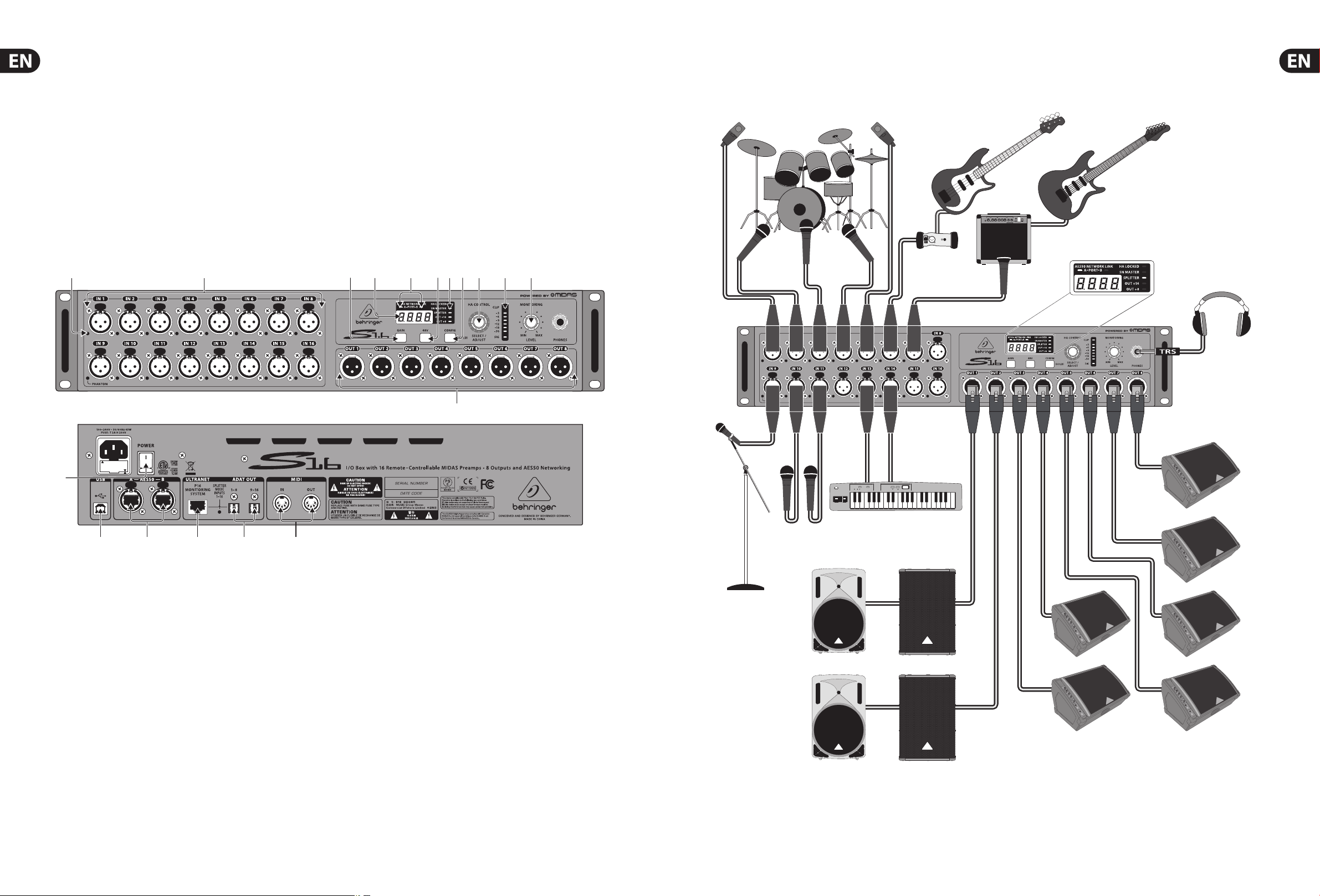
2. Callouts
(1)
(2)
Dual AES50 jacks allow transmission of all audio and MIDI data to the FOH X32
with a single Ethernet cable, and also allow up to 3 S16s to be cascaded for
maximum channel count. In this scenario, 48 bidirectional audio channels at
24-bit / 48 kHz can be transferred on just one CAT5 line between FOH and stage,
including 48 analog inputs from stage, 24 analog outputs on stage as well as the
16 Ultranet channels, MIDI data and head amp remote control.
An additional Ultranet output provides the 16 channels for use with BEHRINGER’s
P16 personal monitoring system via Ethernet cable, allowing each musician
to dial in their own custom mix from the stage. A pair of ADAT ports can carry
additional sends to the stage beyond the 8 analog outputs, or split the 16 inputs.
Lastly, a USB jack allows for future rmware updates.
(3) (4) (6) (8)(7) (9) (10) (11)
(5)
3. Hookup Diagrams
Common connections
GTX30
DI Box
XM8500
HPX6000
(13)
(14)
(1)
PHANTOM LEDs light when the 48 V button is engaged for a particularchannel.
(15)
(16)
(17) (18)
(2) MIDAS-designed mic/line inputs accept balanced XLR male plugs.
(3) GAIN button, when pressed and held, displaysthe currently selected
mic input’s gain setting, which may then be adjusted using the
SELECT/ADJUSTknob.
(4) DISPLAY shows the selected channel number, its gain setting, or the sample
rate in SnakeMaster conguration.
(5) NETWORK LINK LEDs light red to indicate the AES50 ports are connected
but not synchronized, and light green to indicate theyare connec ted
andsynchronized.
(6) 48 V button sends phantom power to the currently selected mic input,
indicated by a litbutton when active.
(7) STATUS LEDs show the operation mode of various features. See the Operation
ModeChart for details. The HA LOCKED LED indicates that preamp gain
adjustment has been blocked by the controlling X32. To unlock, open the X32
Setup/Global page and un-check the General Preference ’LockStagebox’.
(8) CONFIG button, when pressed and held, allowsthe device’s operation
modeto be adjusted by the SELECT/ADJUST knob. See Operation Mode Chart
for details.
(12)
(9) SELECT/ADJUST knob scrolls through the 16channels, adjusts the gain
of thecurrently selected input, and changes the operating mode.
Pushrepeatedly to scroll Inputs, Outputs, P16 channels, ADAT outputs,
andStage (onlyinSnakeMaster mode).
(10) LED METER displays the signal level of the currently selected channel.
(11) MONITORING LEVEL knob adjusts the level of the PHONES output.
(12) XLR outputs accept balanced XLR female plugs.
(13) POWER switch turns the unit on and o.
(14) USB input accepts a USB type-B plug for rmware updates via PC.
(15) AES50 ports allow connection to a SuperMAC digital multichannel audio
network via shielded Cat-5e Ethernet cable with terminated ends.
Thisallows connection to digital mixers or cascading of multiple S16 units.
(16) ULTRANET port sends 16 channels to a Behringer P-16 personal
monitoringsystem.
(17) ADAT OUT jacks send AES50 channels 17-32 to external equipment via optical
cable, or split the local 16 inputs for direct ADAT recording.
(18) MIDI IN/OUT jacks accept standard 5-pin MIDI cables for MIDI communication
to and from an X32 console.
Keyboard
F1320D active monitor
B215D active speaker B1800D PRO
Page 4
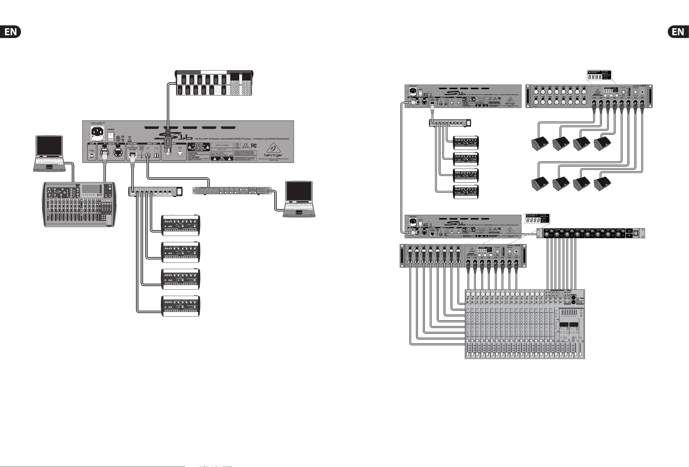
6 DIGITAL SNAKE S16 User Manual 7 DIGITAL SNAKE S16 User Manual
Rear panel connections S16 as standalone snake
X32
Cabling for all AES50 connections
between X32 and S16 stageboxes:
On-stage slave S16 in Standard mode
- Shielded Cat-5e cables only
- Ethercon terminated cable ends
- Maximum cable length 100 meters (300 feet)
FCB1010 MIDI pedal
P16-D
F1320D active monitor
VIEW
VIEW
VIEW
VIEWVIEWVIEWVIEWVIEWVIEW
–
6
VIEW
VIEW
P16-D
FCA1616 interface
P16-M
FOH S16 in Snake Master mode
F1320D active monitor
Rear panel view
ADA8000
P16-M
Front panel view
Out 9-16 (via ADA8000)Out 1-8
(via S16)
to mixer inputs
Sends to stage
SX2442
Page 5

8 DIGITAL SNAKE S16 User Manual 9 DIGITAL SNAKE S16 User Manual
4. Conguring the S16
X32
By using the CONFIG button and SELECT/ADJUST knob, the S16 can be congured
Linking two S16 units
VIEW
VIEW
VIEW
VIEWVIEWVIEWVIEWVIEWVIEW
–
6
VIEW
VIEW
to suit many dierent applications. The STATUS LEDs indicate the current settings.
By holding the CONFIG knob while turning the SELECT/ADJUST knob, you can
scroll through all 10 conguration options. See the Operation Mode Chart for the
routing details of each conguration setting.
When using multiple S16 units, activating SN(ake) MASTER mode on one unit
allows that unit to control the preamp gain of the second unit. An S16 set to
SN MASTER will also dictate the overall clock synchronization (44.1 or 48 kHz).
The OUT +8 and OUT +16 options shift the XLR outputs for use with multiple
S16s. For example, if a connection scenario involves 3 daisy-chained S16s,
therstunit will carry AES50 channels 1-8. The second unit should be set to
OUT+8 so that its analog outputs carry channels 9-16, and the 3rd S16 should be
set to OUT+16 so that its analog outputs carry channels 17-24. This way you can
provide up to 24 return signals to the stage. Alternatively, you may also use the
same block of 8 output signals on a set of distributed S16 stageboxes.
Thisis useful when using a pair of S16s as a standalone digital snake (16 x 16)
ora 32-channel mic preamp via ADAT. See the ’Standalone Operation’ section
IN 1-16
fordetails.
SPLITTER mode routes the 16 local analog inputs directly to the ADAT outputs and
P16 output. This is useful when using the S16 as a standalone snake where the
P16 monitor mix cannot be adjusted from an X32 console. Additionally, the S16
can be used as a high-quality mic preamp that sends the 16 inputs to an interface
or computer with an ADAT card for recording purposes. When SPLITTER mode
OUT 1-8
is o, the ADAT outputs carry AES50 channels 17-32 and the P16 output carries
channels 33-48.
DIGITAL SNAKE S16 Operation Mode Chart
IN 17-32
OUT 17-24
OUT 25-32
ADA8000
OUT 9-16
Seq.
LED
SN MASTER
sync clock
1 (default) AES50 (console)
2 AES50 (console) on
3 AES50 (console) on
4 AES50 (console) on
5 AES50 (console) on on
6 AES50 (console) on on
7 on 48 kHz (int)
8 on 44.1 kHz (int)
9 on 48 kHz (int) on
10 on 44.1 kHz (int) on
LED
SPLITTER
LED
OU T +1 6
LED
OUT +8
XLR analog
out 1- 8
= AES50-A,
ch01-ch08
= AES50-A
ch09-ch16
= AES50-A
ch17-ch24
= AES50-A,
ch01-ch08
= AES50-A
ch09-ch16
= AES50-A
ch17-ch24
= AES50-A,
ch01-ch08
= AES50-A,
ch01-ch08
= AES50-A,
ch01-ch08
= AES50-A,
ch01-ch08
ADAT
out 1- 8
= AES50-A
ch17-ch24
= AES50-A
ch17-ch24
= AES50-A
ch17-ch24
= Local In
01 - 08
= Local In
01 - 08
= Local In
01 - 08
= AES50-A,
ch01-ch08
= AES50-A,
ch01-ch08
= Local In
01 - 08
= Local In
01 - 08
ADAT
ou t 9 -16
= AES50-A
ch25-ch32
= AES50-A
ch25-ch32
= AES50-A
ch25-ch32
= Local In
09 - 16
= Local In
09 - 16
= Local In
09 - 16
= AES50-A
ch09-ch16
= AES50-A
ch09-ch16
= Local In
09 - 16
= Local In
09 - 16
P-16 Ultranet
ou t 1-1 6
= AES50-A
ch33-ch48
= AES50-A
ch33-ch48
= AES50-A
ch33-ch48
= Local In
01 - 16
= Local In
01 - 16
= Local In
01 - 16
= AES50-A
ch01- ch16
= AES50-A
ch01- ch16
= Local In
01 - 16
= Local In
01 - 16
ADA8000
Note: The signals on both S16 units (Out 1-8 and 9-16) and both ADA8000 units
(Out 17-24 and 25-32) are fully dened on the X32’s ’Routing/AES50 Output’ page.
The second S16’s outputs must be set to Out +8 on the unit itself.
Page 6

10 DIGITAL SNAKE S16 User Manual 11 DIGITAL SNAKE S16 User Manual
4.1 Standard Operation
The S16 is in Standard (default) mode when all the conguration STATUS LEDs
on the front display are o. This is useful for using the unit as a digital snake
along with the X32 console to conveniently transfer 16 channels from the
stage to FOH, andsend40 total channels back to the stage. The sends to the
stage are arranged as AES50 channels 1-8 which appear on the 8 analog XLR
OUTPUTS, AES50 channels17-24 and 25-32 which appear on the ADAT OUTPUTS,
andAES50channels 33-48 appearing at the P16 OUTPUT. The specic routing
ofthe AES50 channels can be congured on the X32.
4.2 Cascaded Operation
To make use of the S16’s full potential, up to 3 units can be cascaded to allow
48channels of bidirectional audio. Any AES50 signals cascaded from one S16’s
port A to another S16’s port B are automatically shifted up 16 channels,
allowingthe last S16 in the chain to transmit all audio channels to and from the
stage via its AES50-A port. The X32 Routing home page allows selection of the
incoming AES50 signals that can be connected to the channel processing.
Therouting of the audio sent from console to stage box can be adjusted on the
X32 Routing AES50 pages, respectively.
Signals sent from the X32 to the stage are seen the same on all S16 units in the
chain. AES50 channels 1-8 will appear on the XLR OUTPUTS of each unit.
Toachieve maximum output to the stage, the 2nd and 3rd units in the chain
must have their physical OUTPUTS set to OUT +8 and OUT +16 respectively.
The following chart details the signal ow to and from the stage when
using3S16 units.
Page 7
12 DIGITAL SNAKE S16 User Manual 13 DIGITAL SNAKE S16 User Manual
5. Standalone Operation
The S16 does not necessarily need to be used in conjunction with the X32 console.
A pair of S16 units can be linked to send 16 channels to and from the stage,
providing a high-quality digital snake that can work with any analog mixer.
In this scenario, a master S16 will be placed at FOH near the main mixing console,
and the other on the stage (see ’S16 as standalone snake’ hookup diagram).
TheFOH unit must be set to SN MASTER mode so that it can control the preamps
of the unit on stage. All sends from FOH to the stage can be connected to
INTPUTS 1-8 on the ’master’ S16, which will appear at the on-stage unit ’s XLR
OUTPUTS. Connect all the sound sources from the performers to INPUTS 1-16 of
the on-stage S16. Channels 1-8 will appear at the ’master’ S16’s XLR OUTPUTS and
channels 9-16 will appear at the ADAT OUTPUT. Connect the ADAT 9-16 OUTPUT to
an ADA8000 or similar preamp to provide analog XLR outputs. The outputs from
the ’master’ S16 and the ADA8000 can be connected to any sort of main console
for mixing, analog or digital.
Note - when using a pair of S16 units as a standalone digital snake,
themaster unit at FOH is able to control the mic gains of the unit(s) on stage.
However,inorder to do so, one must press the SELECT/ADJUST button on
themaster unit so that the display reads “St 1”.
For recording applications, a single S16 can also be used as a high-quality mic
preamp. Connect the sound sources to the INPUTS 1-16, and send those channels
via ADAT to an interface or ADAT card installed in your computer. For this scenario,
the S16 must be set to SPLITTER mode.
6. MIDI Communication
The S16 head amp gain and phantom power settings can be controlled remotely
via MIDI whenever it is used standalone, independent from X32 console products.
Note: The S16 will only accept MIDI controls when its preamps are not controlled
via AES50 already. Connection to an X32 series console or another S16 in SN
Master mode will always inhibit reception of preamp related MIDI commands.
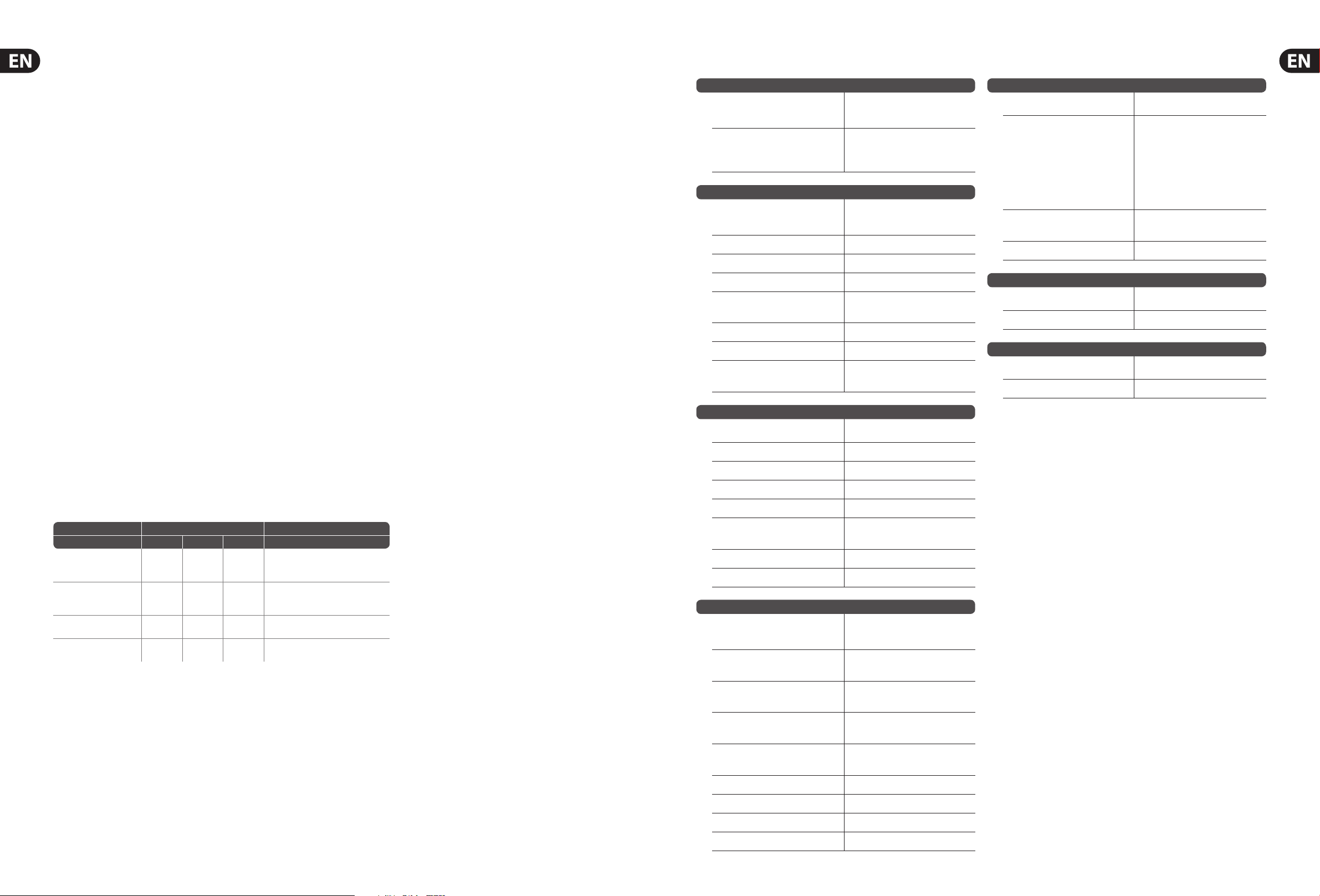
7. Specications
Processing
A/D-D/A conversion 24-bit @ 44.1 / 48 kHz,
(Cirrus Logic A/D CS5368, D/A CS4385) 114 dB dynamic range
Networked I/O latency 1.1 ms
(stagebox in > console processing* >
stagebox out)
Connectors
XLR inputs, programmable mic 16
preamps, designed by MIDAS
XLR outputs 8
Phones outputs, ¼" TRS 1 (mono)
AES50 ports, SuperMAC 2
P-16 connector, 1
Ultranet (no power supplied)
MIDI inputs / outputs 1 /1
ADAT Toslink outputs (2x 8 Ch) 2
USB type B, rear panel, 1
for system updates
Mic Input Characteristics
Design MIDAS
THD + noise, 20 dB gain, 0 dBu out < 0.006 % A-weighted
Input impedance XLR, unbal. / bal. 5 kΩ / 10 kΩ
Indicators
Display 4-digit, 7-segment, LED
Front status LEDs AES50-A, red/green
AES50-B, red/green
HA Locked, red
SN Master, green
Splitter, orange
Out +16, orange
Out +8, orange
Meter Sig, -30 dB, -18 dB, -12 dB, -9 dB,
-6dB, -3 dB, Clip
Rear panel Splitter mode, orange
Power
Switch-mode autorange power supply
100-240 V (50/60 Hz)
Power consumption 45 W
Physical
Dimensions 482 x 225 x 89 mm (19 x 8.9 x 3.5")
Weight 4.7 kg (10.4 lbs)
*) incl. all channel a nd bus processing, e xcl. insert ef fects and li ne delays
AES50 is crea ted and owned by the Aud io Engineering So ciety. ADAT is a registered t rademark of
inMusic Bran ds, Inc. Toslink is a regist ered trademark of Toshi ba Corporation. C irrus Logic is a tra demark
of Cirrus Lo gic, Inc.
The standard channel for transmit/receive of MIDI controls is 1. MIDI channel 2 is
used when the SN slave unit is to be controlled via the SN Master unit.
TRANSMIT / RECEIVE
Select CC # Value Channel Description
SN MASTER “I n 1-16” (FOH)
SN MASTER
“St 1-16” (Stag e)
SN SLAVE - - -
Ext Syn c w/o
AES50 preamp control
80…9 5
96…111
80…9 5
96…111
80…9 5
96…111
0…1 9
0, 127
0…1 9
0, 127
0…1 9
0, 127
Controls l ocal head amps of mas ter unit
1
Gain In 1-16, -2.5…+45 dB, 2.5 dB ste ps
1
48V Phanto m 1-16 on/o
Controls r emote head amps of slave un it
2
Gain In 1-16, -2.5…+45 dB, 2.5 dB ste ps
2
48V Phanto m 1-16 on/o
No MIDI tran smission or recept ion when
controll ed by SN Master or X32 cons ole
1
Gain In 1-16, -2.5…+45 dB
1
48V Phanto m 1-16 on/o
Note: The string 0xEE, 0x7E, 0x7E can be sent for testing if an S16 is
communicating via MIDI. The response would be 0xEE, 0x7E, 0x7F when
MIDIinputs and outputs of S16 are connected to the test interface.
Non clip maximum input level, XLR +23 dBu
Phantom power, switchable per input 48 V
Equivalent input noise level, -128 dBu
XLR (input shorted)
CMRR, XLR, @ 20 dB gain (typical) > 70 dB
CMRR, XLR, @ 40 dB gain > 80 dB
Input/Output Characteristics
Frequency range, @ 48 kHz 10 Hz - 22 kHz
sample rate, 0 dB to -1 dB
Dynamic range, analog in to analog 106 dB
out (typical)
A/D dynamic range, preamp and 109 dB
converter (typical)
D/A dynamic range, 108 dB
converter and output
Cross talk rejection @ 1 kHz, 100 dB
adjacent channels
Output level, XLR, nom./max. +4 dBu / +21 dBu
Output impedance, XLR, unbal. / bal. 75 Ω / 75 Ω
Phones output impedance / level 40 Ω / +25 dBm (mono)
Residual noise level, XLR and TRS -87 dBu A-weighted
Page 8

14 DIGITAL SNAKE S16 User Manual 15 DIGITAL SNAKE S16 User Manual
FEDERAL COMMUNICATIONS
COMMISSION COMPLIANCE
INFORMATION
DIGITAL SNAKE S16
Responsible Party Name: MUSIC Group Services US Inc.
Address: 18912 North Creek Parkway,
Suite 200 Bothell, WA 98011,
USA
Phone Number: +1 425 672 0816
DIGITAL SNAKE S16
complies with the FCC rules as mentioned in the followingparagraph:
This equipment has been tested and found to comply with the limits for a ClassB
digital device, pur suant to part 15 of the FCC Rules. These limits are designed
to provide reasonable protection against harmful interference in a residential
installation. This equipment generates, uses and can radiate radio frequency
energy and, if not installed and used in accordance with the instructions, may cause
harmful interference to radio communications. However, there is no guarantee that
interference will not occur in a particular installation. If this equipment does cause
harmful interference to radio or television reception, which can be determined
by turning the equipment o and on, the user is encouraged to try to correct the
interference by one or more of the followingmeasures:
• Reorient or relocate the receiving antenna.
• Increase the separation between the equipment and receiver.
• Connect the equipment into an outlet on a circuit dierent from that to which the
receiver is connected.
• Consult the dealer or an experienced radio/TV technician forhelp.
This device complies with Part 15 of the FCC rules. Operation is subject to the
following two conditions:
(1) this device may not cause harmful interference, and
(2) this device must accept any inter ference received, including inter ference that may
cause undesired operation.
Important information:
Changes or modications to the equipment not expressly approved by MUSIC Group
can void the user’s authority to use the equipment.
Page 9

We Hear You
 Loading...