

Page 1
User Manual
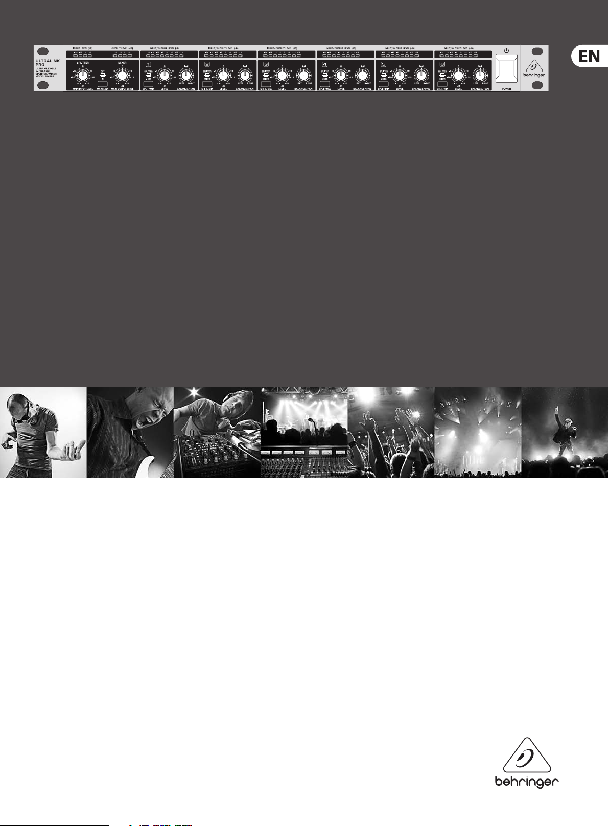
ULTRALINK PRO MX882
Ultra-Flexible 8-Channel Splitter/Mixer
Page 2

2 ULTRALINK PRO MX882 User Manual
Table of Contents
Important Safety Instructions ...................................... 3
Legal Disclaimer ............................................................. 3
Limited warranty ............................................................ 3
1. Introduction ............................................................... 4
2. The Design Concept ..................................................4
2.1 High quality components and design......................... 4
2.2 Inputs and outputs ............................................................ 4
2.2.1 Balanced inputs and outputs ................................... 4
3. Installation ................................................................. 5
3.1 Rack mounting ..................................................................... 5
3.2 Mains voltage ....................................................................... 5
3.3 Audio connections ............................................................. 5
4. Control Elements ....................................................... 6
4.1 The front panel control elements ................................. 6
4.2 The rear panel elements .................................................. 6
5. Block Diagram ............................................................7
6. Applications ............................................................... 8
6.1 Application as a mixer ....................................................... 8
6.2 Application as a splitter .................................................... 9
6.2.1 The ULTRALINK PRO as a 4-channel
stereo splitter ............................................................................ 9
6.3 Application as a matching amplier .......................... 10
7. Specications ........................................................... 11
Page 3
3 ULTRALINK PRO MX882 User Manual
9. Do not defeat the safety purpose of the polarized
TO BIND MUSICGROUP BY ANY EXPRESS OR IMPLIED
Important Safety Instructions
Terminals marked with this symbol carr y
electrical current of su cient magnitude
to constitute risk of electric shock.
Use only high-quality professional speaker cables with
¼" TS or twist-locking plugs pre-installed. Allother
installation or modi cation should be performed only
by quali edpersonnel.
This symbol, wherever it appears,
alertsyou to the presence of uninsulated
dangerous voltage inside the
enclosure-voltage that may be su cient to constitute a
risk ofshock.
This symbol, wherever it appears,
alertsyou to important operating and
maintenance instructions in the
accompanying literature. Please read the manual.
Caution
To reduce the risk of electric shock, donot
remove the top cover (or the rear section).
No user serviceable parts inside. Refer servicing to
quali ed personnel.
Caution
To reduce the risk of re or electric shock,
do not expose this appliance to rain and
moisture. The apparatus shall not be exposed to dripping
or splashing liquids and no objects lled with liquids,
suchas vases, shall be placed on the apparatus.
Caution
These service instructions are for use
by quali ed ser vice personnel only.
Toreduce the risk of electric shock do not perform any
servicing other than that contained in the operation
instructions. Repairs have to be performed by quali ed
servicepersonnel.
or grounding-type plug. A polarized plug has two blades
with one wider than the other. A grounding-type plug
has two blades and a third grounding prong. The wide
blade or the third prong are provided for your safety. Ifthe
provided plug does not t into your outlet, consult an
electrician for replacement of the obsolete outlet.
10. Protect the power cord from being walked on or
pinched particularly at plugs, convenience receptacles,
and the point where they exit from the apparatus.
11. Use only attachments/accessories speci ed by
themanufacturer.
12. Use only with the
cart, stand, tripod, bracket,
or table speci ed by the
manufacturer, orsold with
the apparatus. When a cart
is used, use caution when
moving the cart/apparatus
combination to avoid
injury from tip-over.
13. Unplug this apparatus during lightning storms or
when unused for long periods of time.
14. Refer all servicing to quali ed service personnel.
Servicing is required when the apparatus has been
damaged in any way, such as power supply cord or plug
is damaged, liquid has been spilled or objects have fallen
into the apparatus, the apparatus has been exposed
to rain or moisture, does not operate normally, or has
beendropped.
15. The apparatus shall be connected to a MAINS socket
outlet with a protective earthing connection.
16. Where the MAINS plug or an appliance coupler is
used as the disconnect device, the disconnect device shall
remain readily operable.
UNDERTAKING OR REPRESENTATION. THIS MANUAL
IS COPYRIGHTED. NO PART OF THIS MANUAL MAY
BE REPRODUCED OR TRANSMITTED IN ANY FORM
OR BY ANY MEANS, ELECTRONIC OR MECHANICAL,
INCLUDING PHOTOCOPYING AND RECORDING OF ANY
KIND, FOR ANY PURPOSE, WITHOUT THE EXPRESS
WRITTEN PERMISSION OF MUSICGROUPIPLTD.
ALL RIGHTS RESERVED.
© 2013 MUSICGroupIPLtd.
Trident Chambers, Wickhams Cay, P.O. Box 146,
Road Town, Tortola, British Virgin Islands
LIMITED WARRANTY
For the applicable warranty terms and conditions
and additional information regarding MUSIC Group’s
Limited Warranty, please see complete details online at
www.music-group.com/warranty.
1. Read these instructions.
2. Keep these instructions.
3. Heed all warnings.
4. Follow all instructions.
5. Do not use this apparatus near water.
6. Clean only with dry cloth.
7. Do not block any ventilation openings. Install in
accordance with the manufacturer’s instructions.
8. Do not install near any heat sources such as
radiators, heat registers, stoves, or other apparatus
(including ampli ers) that produce heat.
LEGAL DISCLAIMER
TECHNICAL SPECIFICATIONS AND APPEARANCES
ARE SUBJECT TO CHANGE WITHOUT NOTICE AND
ACCURACY IS NOT GUARANTEED. BEHRINGER,
KLARKTEKNIK, MIDAS, BUGERA, AND TURBOSOUND
ARE PART OF THE MUSIC GROUP MUSICGROUP.COM.
ALL TRADEMARKS ARE THE PROPERTY OF THEIR
RESPECTIVE OWNERS. MUSICGROUP ACCEPTS NO
LIABILITY FOR ANY LOSS WHICH MAY BE SUFFERED
BY ANY PERSON WHO RELIES EITHER WHOLLY OR
IN PART UPON ANY DESCRIPTION, PHOTOGRAPH
OR STATEMENT CONTAINED HEREIN. COLORS AND
SPECIFICATIONS MAY VARY FROM ACTUAL PRODUCT.
MUSIC GROUP PRODUCTS ARE SOLD THROUGH
AUTHORIZED FULLFILLERS AND RESELLERS ONLY.
FULLFILLERSAND RESELLERS ARE NOT AGENTS OF
MUSICGROUP AND HAVE ABSOLUTELY NO AUTHORITY
Page 4

4 ULTRALINK PRO MX882 User Manual
1. Introduction
With the BEHRINGER ULTRALINK PRO you have purchased an ultra-exible
“problem solver” in signal distribution applications, designed to meet
highest requirements: professional recording, broadcast and television
studios, CDand digital production facilities, etc. Much like an all-in-one tool,
itprovides virtually unlimited congurations. Be it the distribution of a stereo
signal to several outputs (splitter); the combination of separate signals to
one stereo output (mixer), or the specic level adaption of individual signals
(bueramplier): theULTRALINK PRO can perform all of these functions
easily - andsimultaneously.
Future-oriented BEHRINGER technology
Our ULTRALINK range of devices has been a hit ever since we introduced our
rst model several years ago. This splitter/mixer is based on many years of
experience and ndings in mixing technology and is used throughout the world
in renowned studios, sound reinforcement systems as well as in broadcast and
televisionstudios.
It was a real challenge to improve the well-known ULTRALINK even further,
andwe are proud of our success. Compared to its predecessor models,
the ULTRALINK PRO not only has additional features, but also comes with
dramatically improved functionality. For example, it now has input and output
level meters and balanced in- and outputs.
The architecture of the ULTRALINK PRO
Typical applications
The ULTRALINK PRO MX882 is one of the most exible systems of its t ype.
Thefollowing applications can be realized:
2 IN/8 OUT splitter, 8 IN/2 OUT mixer, 6 IN/6 OUT matching amplier or any
othercombination.
• Keyboard submixer
• Distribution amplier for P.A. systems, discotheques, theatres, churches,
hotels, communication systems, etc.
• Add-on module for mixer channels
• Add-on module for eect and monitor paths
• Level translator from -10 dBV to +4 dBu etc.
By combining several ULTRALINK PROs you can set up, for instance, a 24-channel
mixer or splitter.
◊ The following operational manual will introduce you to the BEHRINGER
ULTRALINK PRO and its various functions. After reading the manual
carefully, make sure it is always on hand for future reference.
2. The Design Concept
2.1 High quality components and design
Basically, the unit consists of six mono channels, which can be used either as a
splitter or as a mixer. For instance, a stereo program source can be inserted via
the main input to be subsequently routed to any of the mono channels that are
set to SPLIT mode. Using the individual BALANCE/PAN control, you can—for each
channel—determine the ratio between the left and right main input signals that
are routed to the corresponding output of the channels. Thus, the stereo input
signal coming from the main input section can be distributed selectively among
the six mono output channels.
In MIX mode, the input signals from the respective channel(s) can be mixed at
the stereo main output, with the individual BALANCE/PAN control determining
the signal ratio between the left and right main outputs (pan function). It is of
particular advantage that, in MIX mode, the stereo input signal from the main
input section is alternatively routed to the main outputs. By using this feature a
total of up to 8 single signals can be combined.
In MIX mode, the mono input signals are simultaneously applied to the
respective mono outputs, which permits each channel to be used as an individual
matching amplier. The LEVEL controls in the corresponding channels enable
the user to adapt the levels at will, with a maximum gain of +15 dB. Levelsused
in home-recording can therefore be converted into studio levels (+4 dBu),
and vice versa.
The philosophy behind BEHRINGER products guarantees a no-compromise circuit
design and employs the best choice of components. The operational ampliers
NJM4580 which are used in the ULTRALINK PRO, are exceptional. They boast
extreme linearity and very low distortion charac teristics. To complement this
design the choice of components includes high tolerance resistors and capacitors,
detent potentiometers and several other stringently selected elements.
For the rst time, the ULTRALINK PRO MX882 uses SMD technology
(SurfaceMounted Device). These sub-miniature components known from
aerospace technology allow for an extreme packing density and improved
reliability. Additionally, the unit is manufactured in compliance with a ISO9000
certied management system.
2.2 Inputs and outputs
2.2.1 Balanced inputs and outputs
As standard, the BEHRINGER ULTRALINK PRO is installed with electronically
servo-balanced inputs and outputs. The new circuit design features automatic
hum and noise reduction for balanced signals and thus allows for trouble-free
operation, even at high operating levels. Externally induced mains hum etc.
willbe eectively suppressed. The automatic servo-function recognizes the
presence of unbalanced connectors and adjusts the nominal level internally to
avoid level dierences between the input and output signals (correction 6 dB).
Page 5

5 ULTRALINK PRO MX882 User Manual
3. Installation
Your BEHRINGER ULTRALINK PRO was carefully packed in the factory and
the packaging was designed to protect the unit from rough handling.
Nevertheless,we recommend that you carefully examine the packaging and its
contents for any signs of physical damage, which may have occurred in transit.
◊ If the unit is damaged, please do not return it to us, but notify your
dealer and the shipping company immediately, otherwise claims for
damage or replacement may not be granted. Shipping claims must be
made by the consignee.
3.1 Rack mounting
The BEHRINGER ULTRALINK PRO ts into one standard 19" rack unit of space
(1¾"). Please allow at least an additional 4" depth for the connectors on the
back panel. Be sure that there is enough air space around the unit for cooling
and please do not place the ULTRALINK PRO on high temperature devices such as
power ampliers etc. to avoid overheating.
3.2 Mains voltage
Before you connect your ULTRALINK PRO to the mains, please make
sure that your local voltage matches the voltage required by the
unit! Thefuse holder on the female mains connector has 3 triangular markers,
withtwo of these triangles opposing each other. Your ULTRALINK PRO is set to
the operating voltage printed next to these markers, and can be set to another
voltage by turning the fuse holder by 180°. CAUTION: this instruction
does not apply to export models exclusively designed, e.g. for
115 Voperation!
3.3 Audio connections
The audio inputs and outputs on the BEHRINGER ULTRALINK PRO are fully
balanced. If possible, connect the unit to other devices in a balanced
conguration to allow for maximum interference immunity.
Unbalanced ¼" TS connector
strain relief clamp
sleeve
Balanced ¼" TRS connector
strain relief clamp
sleeve
ring
tip
sleeve
ground/shield
ring
cold (-ve)
tip
hot (+ve)
For connection of balanced and unbalanced plugs,
ring and sleeve have to be bridged at the stereo plug.
Balanced use with XLR connectors
12
3
input
1 = ground/shield
2 = hot (+ve)
3 = cold (-ve)
1
2
3
output
For unbalanced use, pin 1 and pin 3
have to be bridged
Fig. 3.1: Dierent plug t ypes
◊ Please ensure that only qualified persons install and operate the
ULTRALINK PRO. During installation and operation the user must have
sufficient electrical contac t to earth. Electrostatic charges might affect
the operation of the ULTRALINK PRO!
tip
sleeve
(ground/shield)
tip
(signal)
Page 6

6 ULTRALINK PRO MX882 User Manual
4. Control Elements
Fig. 4.1: ULTRALINK PRO front p anel
The Behringer ULTRALINK PRO has six identical channels. Each channel is
equipped with two rotary controls, one button and eight LEDs. Moreover there is
a main section with two rotary controls, one button and eight LEDs.
4.1 The front panel control elements
(2)
(5) (8)
(1) (3) (4) (6) (7) (9)
Fig. 4.2: Cont rol elements on th e front panel
(1) The MAIN INPUT LEVEL control sets the main input gain, before the
signal reaches the input bus. In SPLIT mode, the MAIN INPUT LEVEL control
determines the common output level for all mono outputs.
(2) The 4-digit INPUT LEVEL meter informs you about the input level of the
main input within a range from -24 to +6 dB.
(3) By depressing the MAIN LINK switch you can route the MAIN INPUT signal
to the MAIN OUT. This way it is possible to route a maximum of eight input
channels to the main mix.
of +15 dB—allows for converting, e.g., home recording levels (-10 dBV)
intostudio levels (+4 dBu).
(8) The 8-digit OUTPUT LEVEL meter informs you about the output level of each
channel within a range from -24 to +18 dB.
(9) With the BALANCE/PAN control you can set the balance between the left
and right main signals. In SPLIT mode, the main input signal is routed to the
mono output, with the BALANCE control determining the balance beween
the left and right main signal portions. In MIX mode, the mono inputs are
mixed and routed via the LEVEL control to the main outputs, with the PAN
controls determining the allocation of the mono inputs to the left and right
main outputs.
4.2 The rear panel elements
(10) FUSE HOLDER / VOLTAGE SELECTOR. Please make sure that your local
voltage matches the voltage indicated on the unit, before you attempt to
connect and operate the ULTRALINK PRO. Blown fuses may only be replaced
by fuses of the same type and rating.
(11) MAINS CONNECTION. Use the enclosed power cord to connec t the unit to
the mains. Please also note the instructions given in chapter 3“Installation”.
(12) MAIN INPUTS. These are the main audio inputs of your ULTRALINK PRO,
available as balanced XLR connectors. They may feed the mono outputs of all
channels which are operated in SPLIT mode.
(13) MAIN OUTPUTS. These are the main outputs, available as balanced XLR
connectors. They may be fed either by the lef t and right main inputs or by
any of the six mono inputs (or a combination of both).
(4) The MAIN OUTPUT LEVEL control adjusts the output level applied to the
main outputs. The levels present at the six mono outputs are not aected.
Summing the signal levels of several mono channels can overload the main
output stage. The MAIN OUTPUT LEVEL control is therefore used to adjust the
overall output level.
(5) The 4-digit OUTPUT LEVEL meter informs you about the output level of the
main input within a range from -24 to +6 dB.
(6) This SPLIT/MIX switch sets the respective channel to SPLITTER or MIXERmode.
(7) The LEVEL control determines the signal level of the individual channels.
InSPLIT mode, the LEVEL control sets the output level of the mono channels.
In MIX mode, however, it controls the amount of the mono channel’s input
signal feeding into the main output section; at the same time, the level of
the mono channel can be determined, which—owing to the maximum gain
(10) (17) (16) (15) (14) (13) (12)
(11)
Fig. 4.3: Rear panel elements
(14) MONO INPUTS (channel 1 to 4). These are the mono inputs.
Connectiontakes place via balanced XLR connectors.
(15) MONO OUTPUTS (channel 1 to 4). These are the mono outputs, available as
balanced XLR connectors.
(16) MONO INPUTS (channel 5 to 6). These are the mono inputs.
Connectiontakes place via balanced phone jacks.
(17) MONO OUTPUTS (channel 5 to 6). These are the mono outputs, available as
balanced phone jacks.
◊ Please take the time to fill in and return the warranty card within
14 days after the date of purchase, so as to benefit from our extended
warranty. Or use our online registration option available on the World
Wide Web at behringer.com.
Page 7

7 ULTRALINK PRO MX882 User Manual
5. Block Diagram
Fig. 5.1: Block diagram of t he BEHRINGER ULTRALINK PRO MX 882
MAIN Section
Both main inputs interface via the MAIN INPUT LEVEL control with the input
bus as well as with the main outputs. The MAIN OUTPUT LEVEL control
determines the output level of the signals which are summed by the second bus
(i.e., the output bus) and are subsequently routed to the main outputs.
SPLIT Mode
In SPLIT mode, the main input signal is sent via the BALANCE control to
the output buer ampliers of the mono channels, with the LEVEL control
determining the output level of the respective channel. The maximum gain
is+15 dB.
MIX Mode
In MIX mode, the input signals of the mono channels are “collected” via the
LEVEL and PAN controls and are routed to the output bus. In this mode, the LEVEL
control determines the amount of each channel at the output bus, while the PAN
control is responsible for the allocation of the input signal to the left and right
main outputs.
Additionally, the input signal is routed to the respective mono outputs,
i.e., the circuit acts as a matching amplier. The LEVEL control allows for level
compensation of up to +15 dB.
Page 8

8 ULTRALINK PRO MX882 User Manual
6. Applications
6.1 Application as a mixer
Fig. 6.1: Block diagram o f the MIXER funct ion
When the mono channels are operated in MIX mode, a maximum of 8 (6+2)
mono input signals can be summed and routed to the main outputs. In this mode,
the individual signal sources are connected to the mono inputs on the BEHRINGER
ULTRALINK PRO. Each channel has a LEVEL knob to control the amount of its
signal relative to others in the main section. Via the corresponding PAN control,
each mono input signal can be routed either to the left or right main output.
Ofcourse, any intermediate pan settings can be achieved as well. The MAIN
OUTPUT LEVEL control determines the overall level of the main output signal.
Since the two main inputs are alternatively routeable to the main outputs,
twoadditional input signals can be added using the main inputs. For this you
have to depress the MAIN LINK switch. However, as these inputs do not feature
a PAN control, the left main input will always be routed to the left main output;
similarly, the right main input can only be sent to the right main output. A total
of 8 mono channels can thus be routed to two main outputs.
Page 9

9 ULTRALINK PRO MX882 User Manual
6.2 Application as a splitter
Fig. 6.2: Blo ck diagram of the SPLI TTER functio n
A splitter is a distribution amplier which allows for splitting a specic input
signal to several outputs. This function is of use, e.g., in a large-scale sound
reinforcement system where the mixer’s output signal needs to be allocated
to several power ampliers. Another eld of application is in tape duplication
systems, where one master tape machine is to be interfaced with several tape
duplication recorders.
In this mode, the output signal from the mixer is applied to the main inputs of
the BEHRINGER ULTRALINK PRO. If the SPLIT/MIX switches are set to “SPLIT”,
themono outputs of the respective channels provide either the left or the right
main signal. Depending on the setting of the BALANCE control, any balance
between lef t and right main signal can be adjusted.
At the same time, the main input signal is also sent to the left or right main
output, so that here two additional splitter outputs are available. Please note
that these outputs do not feature a balance routing function. The left main input
is routed exclusively to the left main output; similarly, the right main input feeds
the right main output only.
6.2.1 The ULTRALINK PRO as a 4-channel stereo splitter
For this special application, the splitter function congures the unit as a
4-channel stereo splitter. Here, the stereo signal source is connected to the two
main inputs. If all mono channels are operated in SPLIT mode, the BALANCE
controls of channels 1, 3, and 5 are set to “LEFT”, and the BALANCE controls of
channels 2, 4, and 6 to “RIGHT”: thus, the corresponding stereo output pairs
are routed through channels 1+2, 3+4, and 5+6. This kind of application is
particularly useful for tape duplication systems.
Page 10

10 ULTRALINK PRO MX882 User Manual
6.3 Application as a matching amplier
Fig. 6.3: Bloc k diagram of the MATCHING AMPLI FIER function
The BEHRINGER ULTRALINK PRO can also be used as a multiple matching
amplier. The task of a matching amplier is to convert the level of a signal
source into another level. For instance, a cassette recorder with home recording
level (-10 dBV) can be raised to studio level (+4 dBu). Of course, this process can
also be reversed (level attenuation).
In this application, the ULTRALINK PRO is operated in MIX mode. The output
of the signal source is connected to the mono input of the ULTRALINK PRO.
Thecorresponding mono output provides the resulting output signal which can
be raised or lowered in level. Each of the six mono channels is equipped with a
LEVEL control. The control range is from -∞ (full attenuation) to a maximum gain
of +15 dB.
Page 11

11 ULTRALINK PRO MX882 User Manual
7. Specications
Audio Inputs
Connectors XLR and ¼" TRS
Type RF ltered, servo-balanced input
Impedance 50 kOhms balanced,
25 kOhms unbalanced
Nominal operating level -10 dBV to +4 dBu
Max. input level +21 dBu balanced and unbalanced
CMRR Typ. 40 dB, > 55 dB @ 1 kHz
Audio Outputs
Connectors XLR and ¼" TRS
Type Electronically ser vo-balanced
outputstage
Impedance 60 Ohms balanced,
30 Ohms unbalanced
Max. output level +22 dBu balanced and unbalanced
System Specications
Frequency response 5 Hz to 200 kHz, +/-3 dB
S/N ratio >95 dBu, unweighted, 22 Hz to 22 kHz
Power Supply
Mains Voltages
USA/Canada 120 V~, 60 Hz
U.K./Australia 240 V~, 50 Hz
Europe 230 V~, 50 Hz
General Export Model 100 - 120 V~, 200 - 240 V~, 50 - 60 Hz
Power Consumption max. 35 Watts
Fuse 100 - 120 V~: T 630 mA H
200 - 240 V~: T 315 mA H
Mains Connection Standard IEC receptacle
Physical/Weight
Dimensions (H x W x D) approx. 8.5 x 1.75 x 19"
approx. 217 x 44.5 x 483 mm
Net Weight approx. 2.38 kg
Shipping Weight approx. 3.5 kg
BEHRINGER i s constantly str iving to maintain the h ighest profes sional standards. A s a result of these e ffort s,
modific ations may be made f rom time to time to exi sting product s without prio r notice. Specif ications and
appearance m ay differ fro m those listed or sho wn.
THD 0.002% typ. @ +4 dBu, 1kHz, gain 1
Function Controls
Main input level variable
Main ouput level variable
Level variable for each channel
Balance/pan placing in the stereo eld
Function Switches
Main Link links the main input signal to the
mainoutput
Split/mix changeover from split to mix mode for
eachchannel
Indicators
Input level (main) 4-digit LED display: -24/-12/0/+6 dB
Ouput level (main) 4-digit LED display: -24/-12/0/+6 dB
Input/output level 8-digit LED display:
-24/-18/-12/-6/0/+6/+12/+18 dB
Page 12

We Hear You
 Loading...