


 Loading...
User Manual
iNUKE NU6000DSP/NU3000DSP/NU1000DSP
Ultra-Lightweight, High-Density 6000/3000/1000-Watt Power Amplifier with DSP Control and USB Interface

2 |
iNUKE NU6000DSP/NU3000DSP/NU1000DSP User Manual |
|
Table of Contents |
|
|
Thank you........................................................................ |
2 |
|
Important Safety Instructions....................................... |
3 |
|
Legal Disclaimer.............................................................. |
3 |
|
Limited Warranty............................................................ |
3 |
|
1. Introduction................................................................ |
5 |
|
|
1.1 Before you get started....................................................... |
5 |
2. |
Control Elements........................................................ |
5 |
|
2.1 Front panel............................................................................. |
5 |
|
2.2 Rear panel.............................................................................. |
6 |
3. |
DSP Processor............................................................. |
6 |
|
3.1 Processor Functionality..................................................... |
6 |
|
3.2 Front Panel control............................................................. |
6 |
|
3.3 BEHRINGER Amp Remote Software........................... |
10 |
4. |
Applications.............................................................. |
16 |
|
4.1 Bi-amping............................................................................. |
16 |
5. |
Installation................................................................ |
18 |
|
5.1 Rack mounting................................................................... |
18 |
|
5.2 Connections........................................................................ |
18 |
6. |
Specifications........................................................... |
19 |
Thank you
Thank you for choosing a BEHRINGER iNUKE DSP power amplifier. This piece of high-end gear was developed for professional use in live applications, and this amplifier incorporates many ground-breaking features that will make it a useful, dependable, and flexible part of your sound system.
The iNUKE DSP amps feature an onboard Digital Signal Processor for precise, customized control. Multiple routing options, from dual mono to bridged operation, to special functions dedicated to bi-amping applications, give this amplifier unprecedented flexibility. Even better, all of these functions can be controlled remotely from a PC via the downloadable BEHRINGER Amp Remote control software.
This manual first describes the panel controls and connection points before delving into the DSP functionality. Special sections describe how you can program the DSP by using either the amp's front panel controls, or by using the Amp Remote software.
Read this manual and have fun as you become an iNUKE DSP Power User!
3 iNUKE NU6000DSP/NU3000DSP/NU1000DSP User Manual
Important Safety
Instructions
Terminals marked with this symbol carry electrical current of sufficient magnitude to constitute risk of electric shock.
Use only high-quality professional speaker cables with ¼" TS or twist-locking plugs pre-installed. All other installation or modification should be performed only by qualified personnel.
This symbol, wherever it appears,
alerts you to the presence of uninsulated dangerous voltage inside the
enclosure - voltage that may be sufficient to constitute a risk of shock.
This symbol, wherever it appears, alerts you to important operating and maintenance instructions in the
accompanying literature. Please read the manual.
Caution
To reduce the risk of electric shock, do not remove the top cover (or the rear section).
No user serviceable parts inside. Refer servicing to qualified personnel.
Caution
To reduce the risk of fire or electric shock, do not expose this appliance to rain and moisture. The apparatus shall not be exposed to dripping
or splashing liquids and no objects filled with liquids, such as vases, shall be placed on the apparatus.
Caution
These service instructions are for use by qualified service personnel only.
To reduce the risk of electric shock do not perform any servicing other than that contained in the operation instructions. Repairs have to be performed by qualified service personnel.
9.Do not defeat the safety purpose of the polarized or grounding-type plug. A polarized plug has two blades with one wider than the other. A grounding-type plug has two blades and a third grounding prong. The wide
blade or the third prong are provided for your safety. If the provided plug does not fit into your outlet, consult an electrician for replacement of the obsolete outlet.
10.Protect the power cord from being walked on or pinched particularly at plugs, convenience receptacles, and the point where they exit from the apparatus.
11.Use only attachments/accessories specified by
the manufacturer.
12. Use only with the cart, stand, tripod, bracket,
or table specified by the
manufacturer, or sold with the apparatus. When a cart is used, use caution when
moving the cart/apparatus combination to avoid
injury from tip-over.
13.Unplug this apparatus during lightning storms or when unused for long periods of time.
14.Refer all servicing to qualified service personnel. Servicing is required when the apparatus has been damaged in any way, such as power supply cord or plug is damaged, liquid has been spilled or objects have fallen into the apparatus, the apparatus has been exposed
to rain or moisture, does not operate normally, or has been dropped.
15.The apparatus shall be connected to a MAINS socket outlet with a protective earthing connection.
16.Where the MAINS plug or an appliance coupler is used as the disconnect device, the disconnect device shall remain readily operable.
1.Read these instructions.
2.Keep these instructions.
3.Heed all warnings.
4.Follow all instructions.
5.Do not use this apparatus near water.
6.Clean only with dry cloth.
7.Do not block any ventilation openings. Install in accordance with the manufacturer’s instructions.
8.Do not install near any heat sources such as radiators, heat registers, stoves, or other apparatus (including amplifiers) that produce heat.
LEGAL DISCLAIMER
TECHNICAL SPECIFICATIONS AND APPEARANCES ARE SUBJECT TO CHANGE WITHOUT NOTICE AND ACCURACY IS NOT GUARANTEED. BEHRINGER IS PART OF THE MUSIC GROUP (MUSIC-GROUP.COM). ALL TRADEMARKS ARE THE PROPERTY OF THEIR RESPECTIVE OWNERS. MUSIC GROUP ACCEPTS NO LIABILITY FOR ANY LOSS WHICH MAY BE SUFFERED BY ANY PERSON WHO RELIES EITHER WHOLLY OR IN PART UPON ANY DESCRIPTION, PHOTOGRAPH OR STATEMENT CONTAINED HEREIN. COLORS AND
SPECIFICATIONS MAY VARY FROM ACTUAL PRODUCT. MUSIC GROUP PRODUCTS ARE SOLD THROUGH AUTHORIZED FULLFILLERS AND RESELLERS ONLY. FULLFILLERS AND RESELLERS ARE NOT AGENTS OF MUSIC GROUP AND HAVE ABSOLUTELY NO AUTHORITY TO BIND MUSIC GROUP BY ANY EXPRESS OR IMPLIED
UNDERTAKING OR REPRESENTATION. THIS MANUAL
IS COPYRIGHTED. NO PART OF THIS MANUAL MAY BE REPRODUCED OR TRANSMITTED IN ANY FORM OR BY ANY MEANS, ELECTRONIC OR MECHANICAL,
INCLUDING PHOTOCOPYING AND RECORDING OF ANY KIND, FOR ANY PURPOSE, WITHOUT THE EXPRESS WRITTEN PERMISSION OF MUSIC GROUP IP LTD.
ALL RIGHTS RESERVED.
© 2012 MUSIC Group IP Ltd.
Trident Chambers, Wickhams Cay, P.O. Box 146, Road Town, Tortola, British Virgin Islands
LIMITED WARRANTY
For the applicable warranty terms and conditions and additional information regarding MUSIC Group’s
Limited Warranty, please see complete details online at www.music-group.com/warranty.
4 iNUKE NU6000DSP/NU3000DSP/NU1000DSP User Manual
|
(1) |
(3) |
(4) |
(7) |
|||||||||
|
|
|
|
|
|
|
|
|
|
|
|
|
|
|
|
|
|
|
|
|
|
|
|
|
|
|
|
|
|
|
|
|
|
|
|
|
|
|
|
|
|
|
|
|
|
|
|
|
|
|
|
|
|
|
|
|
|
|
|
|
|
|
|
|
|
|
|
|
|
|
|
|
|
|
|
|
|
|
|
|
|
|
|
|
|
|
|
|
|
|
|
|
|
|
|
|
|
|
|
|
|
|
|
|
|
|
|
|
|
|
|
|
|
|
|
|
|
|
|
|
|
|
|
|
|
|
|
|
|
|
|
|
|
|
|
|
|
|
|
|
|
|
|
|
|
|
|
|
|
|
|
|
|
(2) |
(5) |
(6) |
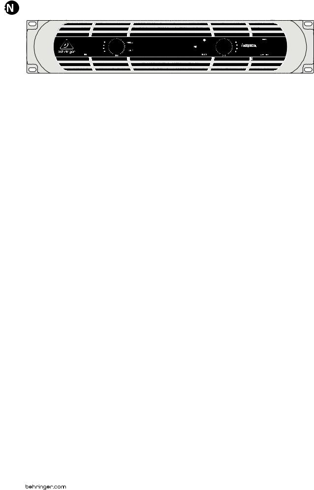
Front panel control elements
1. Introduction
1.1 Before you get started
1.1.1 Shipment
Your iNUKE amplifier was carefully packed at the factory, and the packaging is designed to protect the unit from rough handling. Nevertheless, we recommend that you carefully examine the packaging and its contents for any signs of physical damage that may have occurred during transit.
• If the unit is damaged, please do NOT return it to BEHRINGER, but notify your dealer and the shipping company immediately. Otherwise, claims for damage or replacement may not be granted.
1.1.2 Initial operation
Please make sure the unit is provided with sufficient ventilation, and never place your iNUKE amp on top of other heat-emanating equipment or in the vicinity of a heater to avoid the risk of overheating.
The mains connection is made via the enclosed power cord and a standard IEC receptacle. It meets all international safety certification requirements.
• Please make sure that all units have a proper ground connection. For your own safety, never remove or disable the ground conductor from the unit or the AC power cord.
• The sound quality may diminish within the range of powerful broadcasting stations and high-frequency sources. Increase the distance between the transmitter and the device and use shielded cables for all connections.
1.1.3 Online registration
Please register your new BEHRINGER equipment right after your purchase by visiting http://behringer.com and read the terms and conditions of our warranty carefully.
(8) |
(9) |
Should your BEHRINGER product malfunction, it is our intention to have it repaired as quickly as possible. To arrange for warranty service, please contact the BEHRINGER retailer from whom the equipment was purchased. Should your BEHRINGER dealer not be located in your vicinity, you may directly contact one of our subsidiaries. Corresponding contact information is included in the original equipment packaging (Global Contact Information/European Contact Information). Should your country not be listed, please contact the distributor
nearest you. A list of distributors can be found in the support area of our website (http://behringer.com).
Registering your purchase and equipment with us helps us process your repair claims more quickly and efficiently.
2. Control Elements
2.1 Front panel
(1)USB connection enables firmware updates and control over parameters via computer. Please visit Behringer.com to download DSP control software for your computer. The USB port is for amplifier configuration only.
(2)SIGNAL and LIMIT LEDs display the signal level for each channel. Reduce the input gain if the red LIMIT LED lights up continuously.
(3)CH A/CH B CONTROLS adjust the input level. To increase signal gain, rotate the knobs clockwise; to reduce the gain, rotate the knobs counter-clockwise.
(4)PROCESS button steps through the DSP processing modules.
(5)SETUP button steps through parameters within DSP processing modules.
(6)LCD SCREEN displays the current DSP module and parameter settings.
(7)UP/DOWN/EXIT buttons step through DSP modules and parameters or exit to the top-level iNUKE screen (center button).
(8)SELECT encoder knob toggles between Graphic and Edit modes (when pressed) and changes parameter values (when rotated).
(9)POWER button turns the amplifier on and off.

5 iNUKE NU6000DSP/NU3000DSP/NU1000DSP User Manual
(10)
(11) |
(12) |
(13) |
(14) |
Rear panel control elements (NU6000DSP shown)
2.2 Rear panel
(10)BREAKER (automated fuse, NU6000DSP only). After eliminating the cause of faulty operation, simply depress the BREAKER and power up the unit again. The BREAKER acts in place of common discardable fuses.
(11)POWER SOURCE jack accepts the included IEC power cable.
(12)VENTILATION FAN speed adjusts automatically to ensure trouble-free operation.
(13)TWISTLOCKING SPEAKER OUTPUTS connect the amplifier to the speakers using professional speaker cables with twist-locking plugs.
(14)INPUTS route line-level input signals into these combination jacks using XLR, balanced ¼" TRS, or unbalanced ¼" TS connectors.
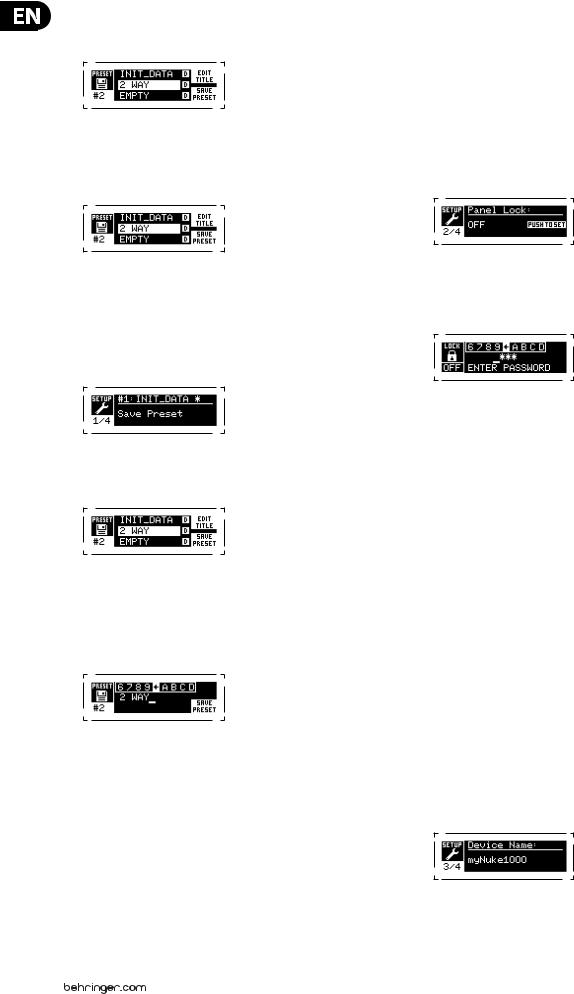
3.2.2 SETUP screens
The SETUP screens access the preset, panel lock, device naming, and LCD screen contrast functions. To access these functions, press the SETUP button, and then move up and down through the top-level screens by pressing either the SETUP button or the UP / DOWN arrow buttons.
SETUP 1/4: Load Preset
The top-level Load Preset screen displays the current Preset name
(up to 10 characters) and Preset number (1–20). Subsidiary screens offer options for loading, saving, and naming Presets.
3. DSP Processor
3.1 Processor Functionality
The iNUKE DSP processor manipulates your signal in the digital domain, offering tremendous flexibility and control. You may control and program the DSP processor via either the iNUKE amplifier’s front panel or remotely by computer using the BEHRINGER Amp Remote software (available for download from behringer.com).
By using the DSP processor, you can program all amplifier functions and parameters—except for the CH A and CH B input gain settings, which can only be controlled using the CH A / CH B knobs on the amplifier’s front panel.
3.2 Front Panel control
The following material describes the DSP's screen organization and how to program the processor's various functions by manipulating your iNUKE amplifier's front panel controls.
3.2.1 Main top-level screen
The top-level screen displays “iNUKE,” as well as the model name: NU1000DSP, NU3000DSP, or NU6000DSP.
Below the Preset name, this screen displays the “Load Preset” option by default. Rotate the SELECT encoder clockwise to access the “Save Preset” option.
Note: Preset #1:INIT_DATA cannot be overwritten. Select this preset any time you want to restore the amp's default settings.
Loading a Preset
1.Make sure the “Load Preset” option appears on the screen. (Rotate the SELECT encoder to toggle between “Load Preset” and “Save Preset.”)
2.Press the SELECT encoder knob to access the DSP’s internal Preset list on the next sub-screen. The correct sub-screen will display the LOAD PRESET option in the upper right-hand corner of the screen.
3.Scroll up and down through the Preset list by rotating the SELECT encoder knob. As you scroll, the Preset number will appear to the left below the disk icon.
4.To load the selected Preset, you may either press the SELECT encoder or press the UP arrow button.
Saving a preset
1.Make sure the “Save Preset” option appears on the screen. (Rotate the SELECT encoder to toggle between “Load Preset” and “Save Preset.”)
6iNUKE NU6000DSP/NU3000DSP/NU1000DSP User Manual
2.Press the SELECT encoder knob to access the DSP’s internal Preset list on the next sub-screen. The correct sub-screen will display the EDIT TITLE and SAVE PRESET options on the right-hand side of the screen.
3.Scroll through the list until you find an EMPTY Preset slot or another Preset you wish to overwrite.
4.If you wish to edit your Preset title before saving, press the UP arrow button to choose the EDIT TITLE option.
5.Edit the Preset title (see “Editing the Preset” title below).
6.Select the SAVE PRESET option by pressing the DOWN arrow key.
Editing a Preset title
1.Make sure the “Save Preset” option appears on the screen. (Rotate the SELECT encoder to toggle between “Load Preset” and “Save Preset.”)
2.Press the SELECT encoder knob to access the DSP’s internal Preset list on the next sub-screen. The correct sub-screen will display the EDIT TITLE and SAVE PRESET options on the right-hand side of the screen.
3.Scroll through the Preset list by rotating the SELECT encoder knob.
4.Select a Preset slot as a save destination by pressing the SELECT encoder knob.
5.Press the UP arrow button to select the EDIT TITLE function. The EDIT TITLE window will appear, with alphanumeric characters in a row at the top and the current title directly below with the editing cursor.
6.Select the backward arrow from the row of characters by rotating the SELECT knob until the backward arrow is highlighted.
7.Press the SELECT encoder knob to erase characters. The cursor will erase characters from right to left across the existing title.
8.Rotate the SELECT encoder to select new characters from the row above the current Preset title.
9.Insert selected characters into the Preset title by pressing the SELECT encoder knob. Once you select and insert a character, the editing cursor will change direction and advance from left to right.
10.Save the new Preset title by pressing the DOWN arrow key to activate the SAVE PRESET function.
SETUP 2/4: Panel Lock
The Panel Lock function uses a 4-character alphanumeric access code to lock the front panel controls and prevent unauthorized changes to DSP settings. Current settings can still be viewed while the unit is locked, but the parameters cannot be changed.
The amplifier can only be locked or unlocked from the Panel Lock screen.
Locking the amplifier
1.Go to the Panel Lock screen by pressing the SETUP button.
2.Press the SELECT encoder knob to access the password screen.
3.Set an access code by using the SELECT encoder knob. Rotate the knob to scroll through the character list, and then select characters by pressing. With each press on the SELECT encoder knob, the password cursor will advance left to right by one space.
4.The amplifier will automatically lock when you select the final character for the access code. The display will flash a brief confirmation message: “Device Locked!”
5.The status displayed on the Panel Lock screen will state “LOCKED!”
Unlocking the amplifier
1.Go to the Panel Lock screen by pressing the SETUP button.
2.Press the SELECT encoder knob to access the password screen.
3.Enter the access code by using the SELECT encoder knob. Rotate the knob to scroll through the character list, and then select characters by pressing. With each press on the SELECT encoder knob, the password cursor will advance left to right by one space.
4.The amplifier will automatically unlock when you select the final character for the access code. The display will flash a brief confirmation message: “Unlocked.”
5.The status displayed on the Panel Lock screen will state “OFF.”
SETUP 3/4: Device Name
Each iNUKE DSP amplifier can be individually named for easy identification within a rack or remotely via the BEHRINGER Amp Remote control software (go to Behringer.com to download the software).
Naming the amplifier
1. Access the Device Name screen by pressing the SETUP button.
7iNUKE NU6000DSP/NU3000DSP/NU1000DSP User Manual
2.Press the SELECT encoder knob to access the editing screen.
3.Choose the backwards arrow by turning the SELECT knob and press it to delete the existing characters of the current preset name.
4.Rotate the SELECT encoder to select new characters from the row above the current amplifier name.
5.Insert selected characters into the new amplifier name by pressing the SELECT encoder knob. Once you select and insert a character, the editing cursor will change direction and advance from left to right.
6.Save the new amplifier name by pressing the DOWN arrow key to activate the SAVE TITLE function.
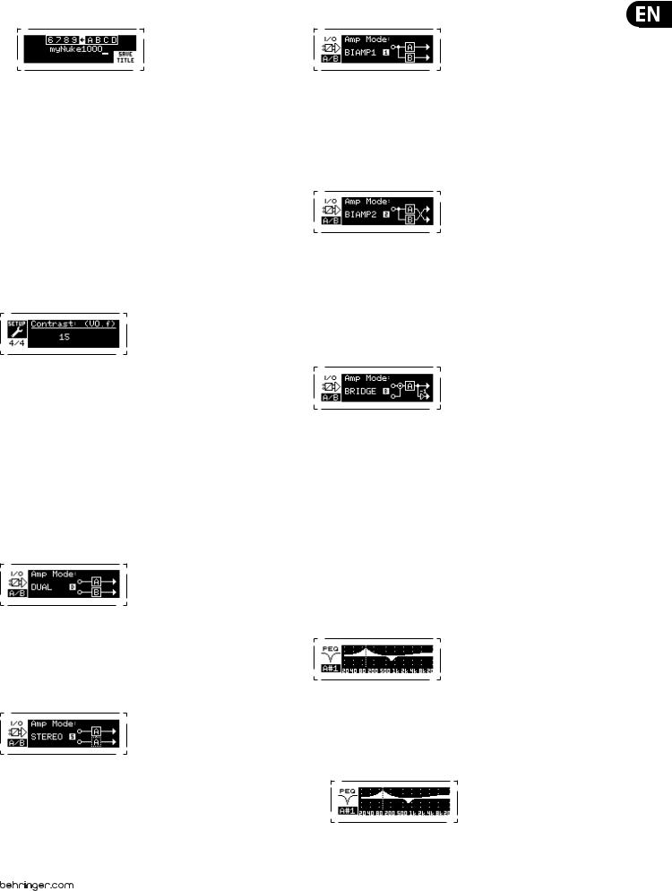
SETUP 4/4: Contrast
The Contrast screen allows you to adjust the LCD screen’s contrast level. The Contrast parameter ranges from 1–30, with 30 representing maximum contrast. Rotate the SELECT encoder knob to adjust the Contrast setting.
3.2.3 PROCESS screens
Pressing the PROCESS button opens up the various screens that determine the signal path setup and that control processing parameters for the DSP modules: I/O, PEQ, XOVER, DEQ, DELAY, and LIMIT.
You can move between top-level module screens by pressing the PROCESS button.
I/O
The I/O module sets up the signal routing inside the DSP from input to output. Press and rotate the SELECT encoder knob to choose between dual mono, stereo, bi-amped, or bridged routing options.
DUAL
DUAL (dual mono) mode routes each channel input, A and B, through completely separate parallel signal paths with independent outputs for each channel.
Each channel may be processed with its own unique filter, equalization, signal delay, and limiter settings.
STEREO
STEREO mode routes the signal from both the A and B inputs through a single series of DSP modules. The parallel DSP modules process the A and B signals with identical, linked settings (only module “A” parameter settings appear on subsequent DSP module screens).
BIAMP1
BIAMP1 mode splits the Channel A input signal at a programmable frequency point, and then routes the resulting high and low frequency signals through a parallel chain of DSP modules with independent equalization, signal delay, and limiter settings. In BIAMP1 mode, Output A routes low frequencies to a low-range speaker, while Output B connects to a high-frequency transducer.
BIAMP2
BIAMP2 mode operates identically to BIAMP1 mode, except that the output signals are swapped between Outputs A and B (i.e., Output B handles low frequencies while Output A handles high frequencies). The swapped A and B output routing allows the user to quickly correct reversed high/low speaker connections without having to physically access the amplifier’s back panel and manually change the speaker connection.
BRIDGE
BRIDGE mode combines the signals from Inputs A and B into a blended mono signal and then routes the resulting mono signal through a single chain of DSP modules, leading to a combined mono output. The mono output signal is identical at Outputs A and B, and the amplifier responds to a single combined speaker load.
PEQ
The PEQ module deploys up to eight EQ bands for precise sound sculpting. The EQ bands can each be switched between low shelving, high shelving, and parametric modes. For the high shelving and low shelving EQ bands,
the LS12 and HS12 settings provide steeper equalization curves than the LS6 and HS6 settings.
The main PEQ screen displays the composite equalization curve across the frequency spectrum.
Programming equalizers
1.Choose individual equalizers by rotating the SELECT encoder knob. As you rotate the SELECT encoder knob, dotted vertical lines will appear at different points within the frequency spectrum, and the EQ band name will appear in the lower-left corner of the screen (e.g., A#1, A#2, B#1, B#2, and so on).
Loading...