

User Manual
EUROLIGHT LC2412
Professional 24-Channel DMX Lighting Console

2 EUROLIGHT LC2412 User Manual
Table of Contents
Thank you .......................................................................2
Important Safety Instructions ...................................... 3
Legal Disclaimer ............................................................. 3
Limited Warranty ...........................................................3
1. Introduction ............................................................... 5
2. Control Elements ....................................................... 6
3. Presets ...................................................................... 11
4. The B Memory Section ............................................ 12
5. Sound-to-Light ........................................................ 14
6. Chase Control ........................................................... 14
7. Additional Functions of the LC2412 ....................... 17
8. Dimmer Control ....................................................... 20
9. Installation ............................................................... 21
10. Specications ......................................................... 23
Thank you
Thank you very much for the condence you have placed in us by purchasing the
EUROLIGHT LC2412. You now own an outstanding, ultra-compact light mixing
console, that features the state-of-the-ar t digital DMX512 control. In addition,
your LC2412 is equipped with an analog output which allows to use it virtually in
every environment you can think of. The design of the LC2412 (how it operates
and how it is programmed) was constructed with controlling dimmer packs and
standard spotlights in mind. To optimally use multi-function spotlights such as
scanners and moving heads, you should use control consoles specically created
for this purpose.
3 EUROLIGHT LC2412 User Manual
9. Do not defeat the safety purpose of the polarized
UNDERTAKING OR REPRESENTATION. THIS MANUAL
ce
electronic components of this product to be free of defects
period is mandated by applicable local laws. If the product
Incase MUSICGroup decides to replace the entire product,
Important Safety Instructions
Terminals marked with this symbol carry
electrical current of su cient magnitude
to constitute risk of electric shock.
Use only high-quality professional speaker cables with
¼" TS or twist-locking plugs pre-installed. Allother
installation or modi cation should be performed only
by quali edpersonnel.
This symbol, wherever it appears,
alertsyou to the presence of uninsulated
dangerous voltage inside the
enclosure-voltage that may be su cient to constitute a
risk ofshock.
This symbol, wherever it appears,
alertsyou to important operating and
maintenance instructions in the
accompanying literature. Please read the manual.
Caution
To reduce the risk of electric shock, donot
remove the top cover (or the rear section).
No user serviceable parts inside. Refer servicing to
quali ed personnel.
Caution
To reduce the risk of re or electric shock,
do not expose this appliance to rain and
moisture. The apparatus shall not be exposed to dripping
or splashing liquids and no objects lled with liquids,
suchas vases, shall be placed on the apparatus.
Caution
These service instructions are for use
by quali ed service personnel only.
Toreduce the risk of electric shock do not perform any
servicing other than that contained in the operation
instructions. Repairs have to be performed by quali ed
servicepersonnel.
1. Read these instructions.
2. Keep these instructions.
3. Heed all warnings.
4. Follow all instructions.
5. Do not use this apparatus near water.
6. Clean only with dry cloth.
7. Do not block any ventilation openings. Install in
accordance with the manufacturer’s instructions.
8. Do not install near any heat sources such as
radiators, heat registers, stoves, or other apparatus
(including ampli ers) that produce heat.
or grounding-type plug. A polarized plug has two blades
with one wider than the other. A grounding-type plug
has two blades and a third grounding prong. The wide
blade or the third prong are provided for your safety. Ifthe
provided plug does not t into your outlet, consult an
electrician for replacement of the obsolete outlet.
10. Protect the power cord from being walked on or
pinched particularly at plugs, convenience receptacles,
and the point where they exit from the apparatus.
11. Use only attachments/accessories speci ed by
themanufacturer.
12. Use only with the
cart, stand, tripod, bracket,
or table speci ed by the
manufacturer, orsold with
the apparatus. When a cart
is used, use caution when
moving the cart/apparatus
combination to avoid
injury from tip-over.
13. Unplug this apparatus during lightning storms or
when unused for long periods of time.
14. Refer all servicing to quali ed service personnel.
Servicing is required when the apparatus has been
damaged in any way, such as power supply cord or plug
is damaged, liquid has been spilled or objects have fallen
into the apparatus, the apparatus has been exposed
to rain or moisture, does not operate normally, or has
beendropped.
15. The apparatus shall be connected to a MAINS socket
outlet with a protective earthing connection.
16. Where the MAINS plug or an appliance coupler is
used as the disconnect device, the disconnect device shall
remain readily operable.
LEGAL DISCLAIMER
TECHNICAL SPECIFICATIONS AND APPEARANCES
ARE SUBJECT TO CHANGE WITHOUT NOTICE AND
ACCURACY IS NOT GUARANTEED. BEHRINGER IS
PART OF THE MUSIC GROUP MUSICGROUP.COM.
ALL TRADEMARKS ARE THE PROPERTY OF THEIR
RESPECTIVE OWNERS. MUSICGROUP ACCEPTS NO
LIABILITY FOR ANY LOSS WHICH MAY BE SUFFERED
BY ANY PERSON WHO RELIES EITHER WHOLLY OR
IN PART UPON ANY DESCRIPTION, PHOTOGRAPH
OR STATEMENT CONTAINED HEREIN. COLORS AND
SPECIFICATIONS MAY VARY FROM ACTUAL PRODUCT.
MUSIC GROUP PRODUCTS ARE SOLD THROUGH
AUTHORIZED FULLFILLERS AND RESELLERS ONLY.
FULLFILLERSAND RESELLERS ARE NOT AGENTS OF
MUSICGROUP AND HAVE ABSOLUTELY NO AUTHORITY
TO BIND MUSICGROUP BY ANY EXPRESS OR IMPLIED
IS COPYRIGHTED. NO PART OF THIS MANUAL MAY
BE REPRODUCED OR TRANSMITTED IN ANY FORM
OR BY ANY MEANS, ELECTRONIC OR MECHANICAL,
INCLUDING PHOTOCOPYING AND RECORDING OF ANY
KIND, FOR ANY PURPOSE, WITHOUT THE EXPRESS
WRITTEN PERMISSION OF MUSICGROUPIPLTD.
ALL RIGHTS RESERVED.
© 2012 MUSICGroupIPLtd.
Trident Chambers, Wickhams Cay, P.O. Box 146,
Road Town, Tortola, British Virgin Islands
LIMITED WARRANTY
§ 1 Warranty
(1) This limited warranty is valid only if you purchased
the product from a MUSIC Group Authorized Reseller in
the country of purchase. A list of authorized resellers can
be found on BEHRINGER’s website behringer. com under
“Where to Buy”, or you can contact the MUSIC Group o
closest to you.
(2) MUSICGroup* warrants the mechanical and
in material and workmanship if used under normal
operating conditions for a period of one (1) year from
the original date of purchase (see the Limited Warranty
terms in §4 below), unless a longer minimum warranty
shows any defects within the speci ed warranty period
and that defect is not excluded under §4, MUSICGroup
shall, at its discretion, either replace or repair the produc t
using suitable new or reconditioned product or parts.
thislimited warranty shall apply to the replacement
product for the remaining initial warranty period, i.e.,
one (1) year (or otherwise applicable minimum warranty
period) from the date of purchase of the original product.
(3) Upon validation of the warranty claim, the repaired
or replacement product will be returned to the user
freight prepaid by MUSICGroup.
(4) Warranty claims other than those indicated above
are expressly excluded.
PLEASE RETAIN YOUR SALES RECEIPT. IT IS YOUR PROOF
OF PURCHASE COVERING YOUR LIMITED WARRANTY.
THIS LIMITED WARRANTY IS VOID WITHOUT SUCH PROOF
OFPURCHASE.
§ 2 Online registration
Please do remember to register your new BEHRINGER
equipment right after your purchase at behringer. com
under “Support” and kindly read the terms and conditions
of our limited warranty carefully. Registeringyour
purchase and equipment with us helps us process
your repair claims quicker and more e ciently.
Thankyouforyour cooperation!
§ 3 Return materials authorization
(1) To obtain warranty service, please contact the
retailer from whom the equipment was purchased.
Should your MUSIC Group Authorized Reseller not be
located in your vicinity, you may contact the MUSICGroup
Authorized Ful ller for your country listed under

4 EUROLIGHT LC2412 User Manual
“Support” at behringer. com. Ifyour country is not
• connection or operation of the unit in any way
This warranty does not detract from the seller’s
Warranty service conditions are subject to change without
listed, please check if your problem can be dealt with
by our “OnlineSupport” which may also be found under
“Support” at behringer. com. Alternatively,please submit
an online warranty claim at behringer. com BEFORE
returning the product. All inquiries must be accompanied
by a description of the problem and the serial number
of the product. Afterverifying the product’s warranty
eligibility with the original sales receipt, MUSICGroup
will then issue a ReturnMaterials Authorization
(“RMA”)number.
(2) Subsequently, the product must be returned in
its original shipping carton, together with the return
authorization number to the address indicated by
MUSICGroup.
(3) Shipments without freight prepaid will not
beaccepted.
§ 4 Warranty Exclusions
(1) This limited warranty does not cover consumable
parts including, but not limited to, fuses and batteries.
Where applicable, MUSICGroup warrants the valves or
meters contained in the product to be free from defects
in material and workmanship for a period of ninety (90)
days from date of purchase.
(2) This limited warranty does not cover the product
if it has been electronically or mechanically modi ed
in any way. If the product needs to be modi ed or
adapted in order to comply with applicable technical
or safety standards on a national or local level, inany
country which is not the country for which the
product was originally developed and manufactured,
thismodi cation/adaptation shall not be considered a
defect in materials or workmanship. Thislimited warranty
does not cover any such modi cation/adaptation,
regardless of whether it was carried out properly or not.
Under the terms of this limited warranty, MUSICGroup
shall not be held responsible for any cost resulting from
such a modi cation/adaptation.
(3) This limited warranty covers only the product
hardware. It does not cover technical assistance for
hardware or software usage and it does not cover
any software products whether or not contained in
the product. Any such software is provided “AS IS”
unless expressly provided for in any enclosed software
limitedwarranty.
(4) This limited warranty is invalid if the
factory- appliedserial number has been altered or
removed from theproduct.
(5) Free inspections and maintenance/repair work
are expressly excluded from this limited warranty,
inparticular, if caused by improper handling of the
product by the user. This also applies to defects caused
by normal wear and tear, in par ticular, of faders,
crossfaders, potentiometers, keys/buttons, guitar strings,
illuminantsand similar parts.
(6) Damage/defects caused by the following conditions
are not covered by this limited warranty:
• improper handling, neglect or failure to operate the
unit in compliance with the instructions given in
BEHRINGER user or service manuals;
that does not comply with the technical or safety
regulations applicable in the country where the
product is used;
• damage/defects caused by acts of God/Nature
(accident, re, ood, etc) or any other condition that
is beyond the control of MUSICGroup.
(7) Any repair or opening of the unit carried out by
unauthorized personnel (user included) will void the
limitedwarranty.
(8) If an inspection of the product by MUSICGroup
shows that the defect in question is not covered by the
limited warranty, the inspection costs are payable by
thecustomer.
(9) Products which do not meet the terms of this
limited warranty will be repaired exclusively at the buyer’s
expense. MUSICGroup or its authorized service center will
inform the buyer of any such circumstance. If the buyer
fails to submit a written repair order within 6 weeks after
noti cation, MUSICGroup will return the unit C.O.D. with
a separate invoice for freight and packing. Such costs will
also be invoiced separately when the buyer has sent in a
written repair order.
(10) MUSIC Group Authorized Resellers do not sell new
products directly in online auctions. Purchasesmade
through an online auction are on a “buyer beware” basis.
Online auction con rmations or sales receipts are not
accepted for warranty veri cation and MUSICGroup will
not repair or replace any product purchased through an
online auction.
§ 5 Warranty transferability
This limited warranty is extended exclusively to the
original buyer (customer of authorized reseller) andis
not transferable to anyone who may subsequently
purchase this product. No other person (reseller,etc.)
shallbe entitled to give any warranty promise on behalf
of MUSICGroup.
§ 6 Claim for damage
Subject only to the operation of mandatory applicable
local laws, MUSICGroup shall have no liability to the buyer
under this warranty for any consequential or indirect
loss or damage of any kind. In no event shall the liability
of MUSICGroup under this limited warranty exceed the
invoiced value of the product.
§ 7 Limitation of liability
This limited warranty is the complete and exclusive
warranty between you and MUSICGroup. It supersedes
all other written or oral communications related to this
product. MUSICGroup provides no other warranties for
this product.
§ 8 Other warranty rights and
nationallaw
(1) This limited warranty does not exclude or limit the
buyer’s statutor y rights as a consumer in any way.
(2) The limited warranty regulations mentioned herein
are applicable unless they constitute an infringement of
applicable mandatory local laws.
(3)
obligations in regard to any lack of conformity of the
product and any hidden defect.
§ 9 Amendment
notice. For the latest warranty terms and conditions
and additional information regarding MUSICGroup’s
limited warranty, please see complete details online at
behringer. com.
* MUSICGroup Macao Commercial O shore Limited of
RuedePequim No. 202-A, Macau Finance Centre 9/J, Macau,
including all MUSICGroup companies

5 EUROLIGHT LC2412 User Manual
1. Introduction
This user’s manual is designed to give you an overview of all the controls, sothat
you get to know all possible applications the LC2412 oers. Generalsafety
instructions are followed by a struc tured overview of the control panel.
Afterwards, all functions of your LC2412 are described in detail.
Future-minded BEHRINGER technology
To allow for the highest possible level of operational safety, we manufacture our
equipment under the highest quality standards in the industry.
Your LC2412 has been manufactured under ISO9000 certied
managementsystem.
◊ The following user’s manual is intended to familiarize you with the
unit’s control elements, so that you can master all the functions.
After having thoroughly read the user’s manual, store it at a safe place
for future reference.
1.1 Before you get started
1.1.1 Shipment
The LC2412 was carefully packed at the assembly plant to assure secure transport.
Should the condition of the cardboard box suggest that damage may have taken
place, please inspect the unit immediately and look for physical indications
ofdamage.
◊ Damaged units should NEVER be sent directly to us. Please inform the
dealer from whom you acquired the unit immediately as well as the
transportation company from which you took delivery of the unit.
Otherwise, all claims for replacement/repair may be rendered invalid.
1.1.2 Initial operation
Please make sure the unit is provided with sucient ventilation, and never place
the EUROLIGHT on top of an amplier or in the vicinity of a heater to avoid the risk
of overheating.
◊ Before plugging the unit into a power socket, please make sure you
have selected the correct voltage:
The fuse compartment near the power plug socket contains three triangular
markings. Two of these triangles are opposite one another. The voltage indicated
adjacent to these markings is the voltage to which your unit has been set up,
and can be altered by rotating the fuse compartment by 180°. ATTENTION: This
does not apply to export models that were for example manufactured
only for use with 120 V!
1.1.3 Warranty
Please take a few minutes and send us the completely lled out warranty
card within 14 days of the date of purchase. You may also register online at
behringer.com. The serial number needed for the registration is located at the top
of the unit. Failure to register your product may void future warranty claims.
1.2 The user’s manual
The user’s manual is designed to give you both an overview of the controls,
aswell as detailed information on how to use them. In order to help you
understand the links between the controls, we have arranged them in groups
according to their function. If you need to know more about specic issues,
please visit our website at http://behringer.com.
1.3 General features and functions
“LC2412” means: 24 preset channels and 12 memory channels. But that’s hardly
all: You can simultaneously control 78 dimmer channels via the DMX512 digital
interface (26 console channels x 3 DMX channels). And because several light units
can be operated on a single dimmer channel, this console gives you a plethora of
mixing possibilities.
Comparable to a mixing console in a recording studio, a light mixing console is a
switching central for stage lighting. Therefore, a light mixing console has to be
absolutely reliable and under no circumstances leave you stranded. We created
our LC2412 using the most modern components in order to guarantee you the
maximum reliability possible.
But without func tionality, no amount of reliability is of use to you. That’s why
we integrated a tremendeous number of func-tions in an extremely compact
unit. You have always full control of the light conditions, regardless whether you
run the light show at a live concert, a club or on a stage. To enable you complete
control over the current setup, the EUROLIGHT LC2412 has an intuitive design
structure and features a large number of LEDs and a large LCD display.
A light mixing console is basically a controlling unit that comprises a full system
once it is integrated with a power source and light elements.
Two dierent standards have established themselves in the eld of light control
(analog controlling with 0 to +10 V and digital controlling via the DMX512 control
protocol). Your LC2412 is compatible with both. The extent of controlling your
lighting situation can range from simply fading lights in and out, all the way to
conguring and programming entire light shows. You can manually control the
speed at which a program runs, enter the desired speed into a preset for each
step, or let it be automatically determined by an internal beat generator. Onthe
other hand, you can control this beat generator by using a fader, or let your
musical program directly determine the beat for the lighting setup.
◊ If you alter the unit’s voltage, you must change the fuses accordingly.
The correct value of the fuses needed can be found in the chapter
“Specifications”.
◊ Faulty fuses must be replaced with fuses of appropriate rating without
exception! The correct value of the fuses needed can be found in the
chapter “Specifications”.
Power is delivered via the cable enclosed with the unit. All requiered safety
precautions have been adhered to.
◊ Please make sure that the unit is grounded at all times. For your own
protection, you should never tamper with the grounding of the cable or
the unit itself.
Presets
Complex lighting situations can be set up using single faders (each controlling up
to 24 channels, whereby up to 72 single dimmers can be controlled). You can light
up individual channels at full blast independently from their fader position using
the FLASH keys.
Memories
Presets can be stored into ten separate preset banks (with twelve memory slots
each), and can also be individually recalled. All memories can be archived by
using separate PCMCIA memory cards.

6 EUROLIGHT LC2412 User Manual
Chases
The expression “Chases” refers to situations in which individually programmed
light steps (up to 99 steps) are executed in succession (the lights “chase” each
other). These steps can be both individual presets as well as memories.
You can create extremely complex chases. For example, parameters such as
fade-in speed of a step, chase sequence speed and their control via the built-in
beat generator or music can all be programmed.
Crossfade
There are several ways to alternate between various stored or newly developed
lighting situations. Conversely, you can also alternate back and forth between
individual steps of a single chase manually or automatically.
Preview
With this function, you can preview stored memories or chases without these
being visible on the stage. This way, you can discretely control the next step
before letting it be seen on the stage.
Sound to light
This function is more widely known as “party light”. It basically means that your
music drives the light show. An incomming music signal is broken down into
three frequenc y ranges (bass, mids and highs), each of which is assigned to a
(memory) channel. Depending on the volume of the respective signal segments,
the lights assigned to them will shine accordingly. You can even program a setup
for song pauses.
MIDI
The LC2412 can be controlled via MIDI. Two EUROLIGHT LC2412s can be operated
as master and slave by using the MIDI interface. Entire shows can be stored and
recalled by means of a MIDI sequencer.
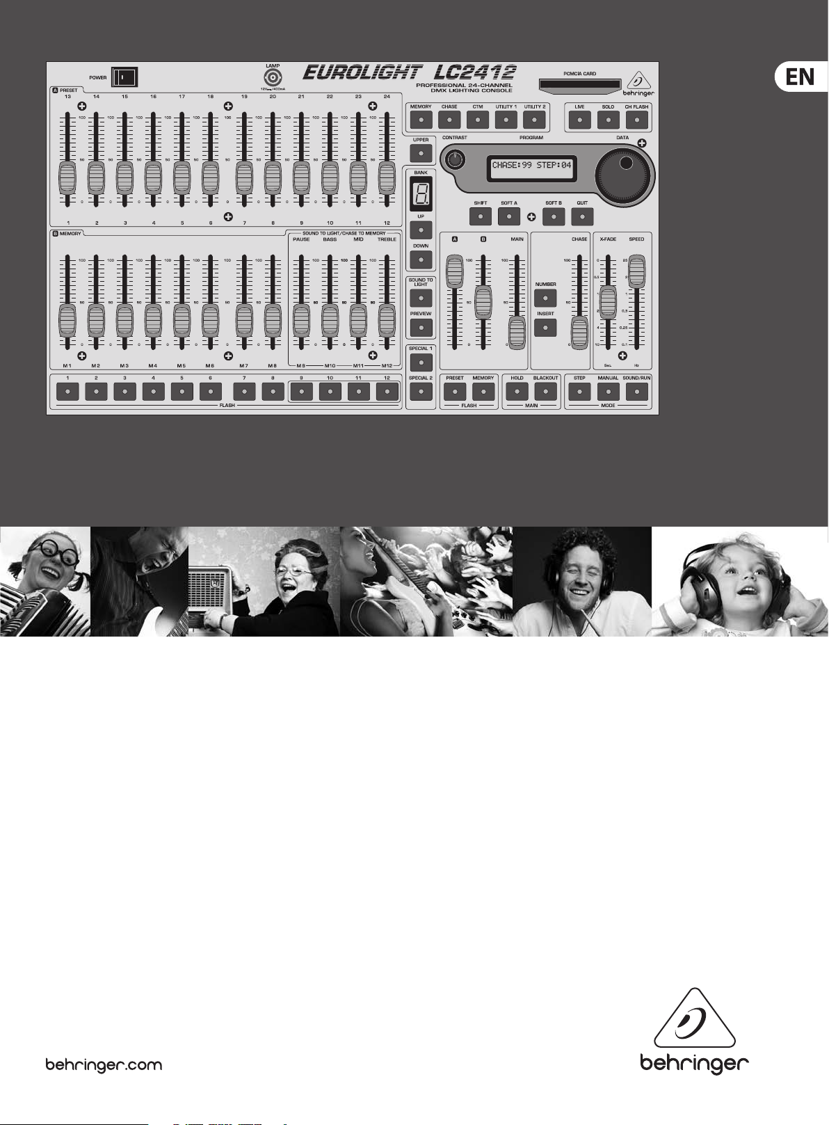
2. Control Elements
The control panel of your LC2412 is divided into various areas with dierent
functions. The way the controls on the LC2412 were designed makes using the
unit and capturing current settings a breeze. The control elements are described
on the following pages according to the functions they play. If parts of the unit
are shown in light grey in an illustration, that means that these controls belong
to another section (described elsewhere in the manual).
All control elements and function keys are provided with control lights to enable
you full oversight of the setup/functions currently selected.
The sections: (1) A PRESET section, (2) B MEMORY-section + bank
display, (3) sound to light, (4) FLASH keys, (5) programming section,
(6) MAIN section, (7) CHASE section.
The LC2412 also has additional functions that cannot be assigned to a particular
section (special channels):
(8) SPECIAL 1 key. Used to activate a special channel, for example for turning a
fog machine on/o.
(9) SPECIAL 2 key. The same function as SPECIAL 1 key. Just like in the case of
other channels, three DMX channels can be assigned to these two channels
(i.e. to SPECIAL 1/2). Both special channels are then labeled as channels
25and 26 on the console. SPECIAL 1 and SPECIAL 2 keys can be programmed
as switches, keys or kill keys. Additional information on this subject can be
found in chapter 7.3.
(10) POWER switch. Used to power up the EUROLIGHT LC2412. The POWER
switch should always be in the “O” position when you connect the unit to
themains.
◊ Please take note: Merely switching the unit of f does not mean that
it is fully disconnected from the mains. When not using the unit for
prolonged periods of time, please unplug the unit ’s power cord from
the power outlet.
DM X512
The DMX digital protocol lets you exibly assign 78 of the 512 digital channels to
individual light console channels (softpatch).
Memory card
The EUROLIGHT LC2412 oers you access to 120 storable lighting setups
(memories) that can easily be altered. A virtually unlimited archive of lighting
setups can be created by using the interchangeable memory cards on which
these setups are stored. The sky is the limit when you put your creativity to the
test with the 99 programmable chases, each consisting of 99 single steps.
(11) The BNC connector is used for connecting a gooseneck lamp (optional).
7 EUROLIGHT LC2412 User Manual
(13) (14) (15) (16) (17)
(10) (11) (5)
(1)
(2)
Fig. 2.1: Section overv iew
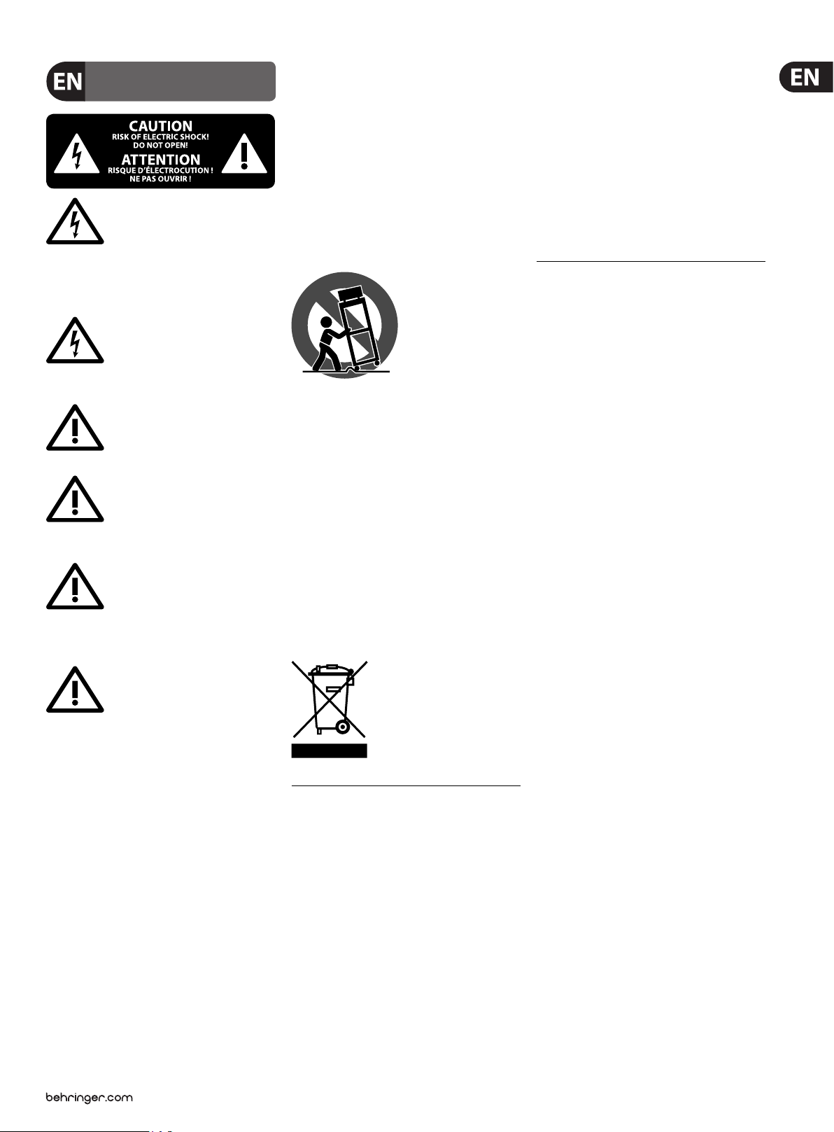
2.1 Control elements of the A PRESET section
(33)
(12)
Fig. 2.2: A PRE SET section (det ail)
(12) Faders 1-12. Used to set the intensity of light elements connected to the
dimmer pack.
(33) UPPER switch. When you press this switch, the A PRESET section is switched
to the twelve additional channels. After that, you can set up the intensity of
channels 13 - 24. See also chapter 3.2.
Setting up presets
Channel faders are used for setting up a preset that can be directly recalled by
moving fader A (41). As in all other setups, the MAIN fader (43) (see chapter 2.6)
determines the maximum illumination level of selected light sources.
2.2 Control elements of the B MEMORY
section( 2 )
The faders of the B MEMORY section are located in the block underneath the
APRESET section.
(13) These faders control the illumination level of an entire group of channels
in a ratio to one another that you previously determined by set ting up the
APRESET faders and saving this setting as a memory.
(18)
(19)
(20)
(21)
Fig. 2.3: B MEMORY s ection
8 EUROLIGHT LC2412 User Manual
(22) (23)
Exception: When the LC2412 is in preset mode (“P” shown in the bank display),
the faders control the same channels as the faders of the A PRESET section.
Thisway, you can simul-taneously create a second preset.
(14) – (17) These faders are also a part of this section, but they have a double
function. When the LC2412 is in sound to light mode (party light function),
they control the illumination level of individual memories assigned to
particular frequency ranges.
(18) The BANK display shows the storage bank to which the memories you recall
belong. It also shows if the LC2412 is currently in preset mode (“P” diplayed).
The display starts ashing when you switch into preset mode, and lights
up constantly after three seconds. The preset mode is active only after the
ashing has stopped. This prevents accidental activation of the preset mode
as well as rough fades.
(19) UP/DOWN keys. Use them to selec t a preset bank (0 - 9) or switch into
preset mode (P). The control lights ash when you select a new bank while
memories from the previous bank are still active (the fader(s) is(are) pulled
up). Pull the fader(s) ((13), (14) - (17)) down to fade the memory out. When you
pull the fader(s) up again, the memory of the new preset bank is visible on
the stage (also see chapter 4.1.2).
(20) SOUND TO LIGHT key. See chapter 2.3.
(21) PREVIEW key. It gives you the option to preview (or modify) stored
memories one more time before implementing them on the stage. Thisis
particularly useful when you saved chases as memories and wish to
double-check and/or modify their speed before integrating them into a
running show. When “preview” is activated, the chases are shown on control
LEDsexclusively.
Each fader is assigned to a FLASH key (section (4) ). This key is used to assign a
specic bank position to individual presets while programming a memory.
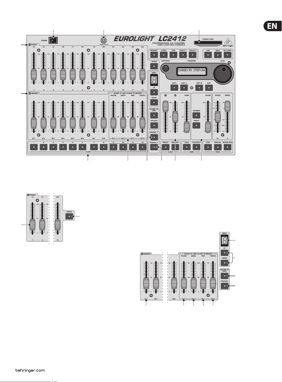
2.3 Control elements of the Sound-to-light
section ( 3 )
The SOUND-TO-LIGHT controls are located in the right-hand sec tion of the
BMEMORY section.
If the sound-to-light function is ac tive, memories 9 - 12 are controlled by a music
signal, whereby the volume of the signal dictates the illumination level of the
memories. The music signal is divided into three frequency ranges (bass,mids,
higs). One memory slot is assigned to each of the three frequency ranges.
Foroptimal results, please put the faders to the middle position. This will let you
bring individual settings of memories into sync with one another, should the
levels vary from memory to memory.
(14) The PAUSE fader is, just like the fader (13), used primarily to control the
illumination level of memories. If the sound-to-light function is active,
itcontrols a memory slot assigned to run during program breaks between
two musical pieces.
(15) The BASS fader takes over the basic conguration of the illumination levels
for the memory slot assigned to the bass por tion of the frequency range.
(16) The MID fader is conversely assigned to the mids.
(17) The TREBLE fader is conversely assigned to the highs.
(18) and (19): Bank display and UP/DOWN keys, see chapter 2.2.
(20) The SOUND-TO-LIGHT key activates the sound-to-light funtion.
The music signal necessary for controlling the show can be fed into the
ANALOGINPUT connector located at the rear of the LC2412.
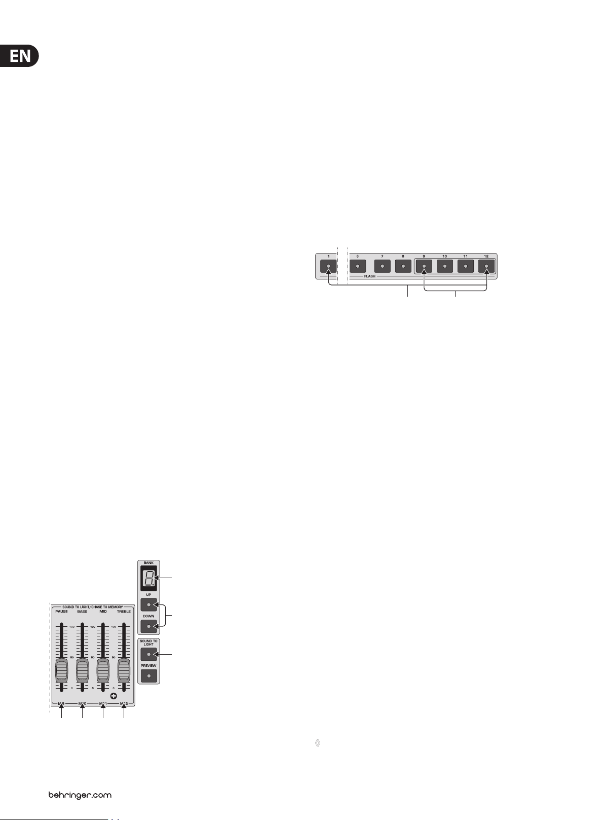
2.4 Section ( 4 ) : FLASH keys and SOLO
Fig. 2.5: The FL ASH keys
(22) FLASH keys. Pressing one of the FLASH keys sets the respective channel to
the maximum illumination level set on the MAIN fader, independent from
its own fader position. For this purpose, the CH FLASH key has to be pressed.
The channel ash function is automatically activated in preset mode.
(23) Dual-function FLASH keys. Memories or chases can be stored to memory
positions 9 - 12 (chase to memory). When a respective storage bank is
selected, chases are indicated with yellow LEDs. Chases can also be recalled
by using the Flash keys.
Solo
When the solo function is simultaneously active (SOLO key (31), LED lit), all other
emitters or light elements are deactivated. Only the channel selected via the
Flash key is still active.
2.4.1 Disabling the solo function
You have the option to exclude specic channels from the solo function, so that
these channels remain active even when “Solo” is activated.
Disabling solo is achieved by performing the folloing programming sequence:
Fig. 2.4: The SOUND -TO-LIGHT sect ion
(18)
(19)
(20)
1. Press UTILITY 1 (28) .
2. Select the option DISABLE SOLO by using the SOFT A key (38) located below
the display. The channel for which the solo function should be disabled
or enabled is shown in the top lef t section of the display. The respective
disabled/enabled status of the said channel is indicated to the right of the
channel number itself.
3. To select the channel you wish to adjust, turn the DATA wheel (36).
Thedesired channel can also be selected by using the Flash key
(for channels 13 - 24: rst press the UPPER key).
4. SOFT B (39) selects “DISABLE” and thus disables the solo function for this
channel; SOFT A selects “ENABLE”.
5. To exit this procedure, press the QUIT key (40), thus conrming the procedure.
◊ When you disable the solo function for a particular channel,
the channel remains active in case when it is part of an activated
memory that fades after pressing one of the FLASH keys.

9 EUROLIGHT LC2412 User Manual
Example:
You have disabled the solo function for channel 8. The light on channel 8 remains
lit if you press one of the Flash keys, as long as the solo function is active.
Previously, you have programmed a memory that uses channel 8. The memory
has just been activated on the stage. Now, press one of the Flash keys (CH FLASH
(32) is also activated). There are two lights on the stage, i.e. channel 8 and the
channel activated with the key!
2.5 Control elements of the programming
section ( 5 )
Despite its compac t size, the EUROLIGHT LC2412 is a versatile light mixing
console. In it, we have integrated a plethora of functions, among others,
variousfunctions for memories, chases and digital control. The basic elements
of the programming section are located at the top right section of the unit.
Tolet you quickly orient yourself in dicult situations, the LC2412 also features
adisplay.
(25) (26) (27) (28) (30) (31) (32)(29) (24)
(33)
(34)
(36)
(35)
(31) SOLO. The solo function utilizes the ash keys. When the solo function is
active, pressing the FLASH key for a single channel/memory completely
dimms all other lights. If so desired, individual channels can be taken out of
the solo function’s reach (see chapters 4.3.1 and 2.4.1).
(32) CH FLASH key. Switches the channel ash function on and o. When the
channel ash function is on, you can use the FLASH keys ((22) + (23)) to
enable the highest illumination level on individual channels. This function is
automatically activated in preset mode (see chapter 3.1.1). However, it has to
be manually activated in memory mode.
(33) UPPER switch. Used to switch over to channels 13 - 24. See also chapters
2.1and 3.2.
(34) CONTRAST control. Turning this pot lets you adjust the display contrast.
(35) PROGRAM display. Depending on the programming procedure,
dierentmenues are shown here. If you haven’t programmed anything
yet, or if you have quit a programming procedure by means of pressing the
QUIT key (40), the display shows the current chase and the respective step
(basicsetup).
(36) DATA wheel. Used to change/select programming parameters. For example,
it can be used for programming chases, during which you dial in steps and
determine their execution speed. Besides, it is also used for directly calling
up chases (see also chapter 6.2).
(37) SHIFT key. Opens additional programming menues. A more detailed
explanation can be found in the description of the respective
programmingprocedures.
(38) SOFT A key. Needed for selec ting items while in a programming menu.
Themenu texts and the SOFT A key are ordered in such a way that this key
lets you select the options above (appearing in the menu).
Fig. 2.6: The programming section
(24) PCMCIA CARD slot. This inter face accepts the memory card on which you
can store your console setups.
(25) MEMORY key. By pressing the MEMORY key once, you initiate the procedure
that saves a stage scene. How this procedure functions in particular is
explained in greater detail in chapter 4.1.
(26) CHASE key. Used to initiate the programming procedure (intended for
creating a chase). How this is done is explained in chapter 6.1.
(27) The CTM key (stands for chase to memory) brings up the menu for storing
chases. Basically, you can store completely programmed chases into
memory. Each of the ten memory banks has four memory slots (9 - 12)
available for this purpose.
(28) UTILITY 1. This key takes you to the following programming menus:
DISABLESOLO, SELECT CURVE and THEATRE MODE.
(29) UTILITY 2. This key takes you to the following programming menus:
DMXPATCH, SELECT MIDI and SELECT SPECIAL. Further information about
these functions is to be found in chapters 7 and 8, “ADDITIONAL FUNCTIONS
OF THE LC2412” and “DIMMER CONTROL”.
(30) LIVE key. By pressing this key, you can route chase or memory steps to
the console’s output in order to see what it would all really look like on
the stage. This also makes sense for the programming procedure itself,
becausechases are for example only shown on the LEDs during their selec tion
(normalsetting, blind mode). This way, selecting chases is even possible while
a program is running on the stage, without disrupting the program itself
(automaticpreview). The live mode changes everything the other way around:
only the settings observed in the preview function are visible on the stage.
(39) SOFT B key. Has the same function as the SOFT A key.
(40) QUIT key. Used for closing a programming procedure and going back to the
main menu.
2.6 Control elements of the main section ( 6 )
(41) (42) (43)
(44) (45) (45) (47)
Fig. 2.7: The main section
Control elements that apply to function groups or the entire console are grouped
in the main section.
(41) A fader. This fader is the master fader for the A PRESET section; it determines
the maximum illumination level of the entire section. The FLASH keys
((22) / (23) as well as (44) / (45)) can still be utilized, even when the fader is at
its zero position.

10 EUROLIGHT LC2412 User Manual
(53) (54) (55)
(56) (57)
(58) (59) (60) (61)
(42) B fader. This fader is the master control for the B MEMORY section;
itdetermines the maximum illumination level of all memories. Just like in
the case of the A fader, the FLASH keys can be utilized even when the fader is
at its zero position.
When the MAIN fader is raised up, both of these faders (A and B) can be used
to fade in and out between the settings of both of these sections.
(43) MAIN fader. It determines the maximum illumination level of all commands
at the console’s output.
(44) PRESET FLASH key. You can execute the entire A PRESET section with this
ash key, that is, activate the A PRESET section on the stage, even if the the
A fader (41) is fully down. As soon as you let go of the key, the lights fade
again. More information about this subject is found in chapter 4.3.
(45) MEMORY FLASH key. Has the same function for the B memory section.
Also, two additional keys in this section aect the entire console output:
(46) HOLD key. Freezes the current settings, while you select a new preset,
recall a dierent memory or implement an entirely dierent conguration.
Thisprocedure is described in chapter 7.2.
(47) BLACKOUT switch. Completely dimms all lighting elements. This function
aects the entire console output, that is, it also aects the chases.
Thedimming is done abruptly. If you want the dimming to take place softly,
use the MAIN fader. Console settings can be altered while the console output
is deactivated. To illuminate the stage again, hit the BLACKOUT key again.
The control LED dies out.
(51) X-FADE control. Used to manually dissolve bet ween individual chase steps.
Can also be used to dissolve between memories. Additionally,fade-in speed of
chase steps can be congured, provided this speed was not already determined
in theatre mode (only when theatre mode is active). Moredetailed information
on this subject can be found in chapters 6.2.3 and 7.4.
(52) SPEED fader. Controls chase speed.
(53) STEP key. Manually triggers chase steps. This can also be done while chases
are already active. This function can also be remotely controlled by using
afootswitch.
(54) MANUAL MODE key. Assigned to the X-FADE control. When the MANUAL MODE
key is activated, turning the X-FADE control back and forth either fades back
and forth between two chase steps (INSERT key activated) or fade chase steps
in after one another (INSERT key deactivated). A more detailed overview of the
various possibilities of fading in/out can be found in chapter6.2.4.
(55) SOUND/RUN MODE key. Selectively activates chase control by means of bass
rythm (SOUND) or by means of the internal speed control (RUN).
2.8 Rear panel connectors of the LC2412
2.7 Control elements of the chase section ( 7 )
(50)
(51) (52)
(48)
(49)
Fig. 2.8: The c hase section
(48) NUMBER key. Selects a chase, enabling you to show individual chases on
the control LEDs (automatic preview). The control LED of the NUMBER key
lights up, as long as chases are active in any form. This means, the LED lights
up even when the chase is not active, but just “dialed in”, ready for action.
Whenyou select a chase whose steps have still not been programmed,
the LED dies out after letting go of the key. The LED also dies out when the
CHASE fader (50) is pulled down.
Fig. 2.9: Digi tal and analog outp uts
(56) DMX512 OUT connector. The digital output of the LC2412 is provided by
means of a 5-pole XLR connector. You can connect a dimmer pack. It can
be used to process digital control commands according to the DMX512
controlprotocol.
(57) ANALOG OUT connector. The analog output is meant for controlling
via the analog standard (0 to +10 V DC) and is implemented as a Sub D
connector. Used to connect dimmer pack that don’t use the modern DMX512
controlprotocol.
Fig. 2.10: Additional back-panel connectors
(58) MIDI OUT connector. MIDI data can be forwarded from the MIDI OUT
connector to a second LC2412 or another MIDI sequencer/PC by using a
corresponding cable (connect it to the MIDI IN connector on the receiving
unit). This lets you control two consoles in parallel, that is, a total of 156 DMX
channels are at your disposal.
(49) INSERT key. Activating this key while a chase is running lets you alternate
between the current step and the one preceeding it by pressing the STEP
key (53). This function can also be executed utilizig the X-FADE control
(MANUALMODE key (54) activated). Additional information on this subject
can be found in chapter 6.2.6.
(50) CHASE fader. Controls the illumination level of a complete chase setup.
Separate ratios of a memory incorporating this chase remain intact.
(59) MIDI IN connector. Used to feed in MIDI data (e.g. from a MIDI sequencer or
another LC2412) to control the LC2412.
(60) ANALOG IN connector. Connect an output of your mixing console, your CD
player or another analog signal source to this ¼" TS mono jack connec tor.
This lets you use the sound-to-light function and musical control of chases.
(61) FOOTSWITCH connector. Connect a footswitch here to remotely control
the STEP key. Additional information about this subject can be found in
chapter6.2.4.

11 EUROLIGHT LC2412 User Manual
A Preset section
3.1 Basic conguration
Pull all the faders all the way down to the zero mark. This way, you assure that
you start your exploration of the possibilities of the LC2412 from a neutral
setting, and can observe the results of the changes you implement directly.
Usethe POWER switch to power up your BEHRINGER EUROLIGHT LC2412.
TheLC2412 displays now the setup that was most recently used, just prior to
being powered down last time.
Fig. 2.11: Serial number and mains connector
(62) SERIAL NUMBER. Please take a few minutes and send to us a completely
lled out warranty card within 14 days of the original date of purchase.
Otherwise, warranty claims may be rendered invalid. Or will out the
warranty information online at behringer.com.
(63) FUSE COMPARTMENT / VOLTAGE SELECTION. Before connecting the unit
to a power outlet, please make sure that the selected voltage matches your
local voltage. When replacing fuses, please make sure that you always use
fuses of the same type. Some units allow for switching between 230 V
und 120 V. Please note: when connecting a unit intended for the European
market to a 120V power outlet, you must also replace the factory fuse with a
higher-value fuse.
Power is supplied via an IEC connector. The matching cable is provided with
the unit.
3. Presets
This chapter describes individual steps used to set up, recall and fade in/out
presets (pre-determined lighting situations). Even though your LC2412 can
execute complex functions, its controls are easy to master, provided you invest
some time to familiarize yourself with the way they work. To familiarize you with
the control elements and their functions step by step, let us begin with setting up
presets (preset = the total collection of all fader positions of the A PRESET section
at one particular time). Let’s start with 12 channels rst.
If you want to start completely from the beginning, you can use a key
combination to erase all programmed congurations. More on this subject
in chapter 7.8.
3.1.1 Preset mode
To work exclusively with presets, you have to rst switch into preset mode.
Select“P” in the bank display accordingly.
1. Press the UP or DOWN keys repeatedly until “P” is shown in the display.
Thedisplay ashes for roughly 3 seconds.
2. Once the ashing stops, your LC2412 is in preset mode. The CHANNEL FLASH
function is now automatically activated, which is also shown by the lit
control LED (CH FLASH (32)).
3. Raise the MAIN fader (43) as well as Fader A (41).
4. You can now use faders 1 - 12 of the A PRESET section to create a stage
design. The illumination level of individual lighting elements can be read out
on the control LEDs, aligned next to the FLASH keys.
◊ You can not program or recal memories while in preset mode. On the
other hand, stored chases can be recalled whle in preset mode.
3.2 Expanding to 24 preset channels
(uppermode)
All operations applicable to channels 1-12 can be executed on channels 13 - 24,
once you switch into upper mode.
All statements referring to channels 1 - 12 apply also to channels 13 - 24
(uppermode).
◊ Think of presets as building blocks used to create more complex
lighting situations: memories capture the setup of a preset
(up to 24 channels) on one fader; chases use presets (level step)
as well as memories (memor y step) as single steps.
Chase memory
Level steps
Memory steps
1. Press the UPPER switch (33) .
The control LED indicates that the LC2412 is now in upper mode, that
is, thatthe faders of the A PRESET section now control channels 13 - 24.
Thefaders from the B MEMORY section aect channels 13 - 24 while in
preset mode.
2. Set up your preset by moving the faders of the A PRESET section into the
desired position.
In case you had already executed setups to channels 13 - 24, you have to
rst put the faders into the previously selected position before being able to
again align these channels.
3. To quit upper mode, simply press the switch.
◊ After switching over, the control LEDs indicate the illumination
condition of the respective active channels independent of the position
of the faders. To alter the setting of a channel, you have to first bring
the respective fader into the previous position.
Additional features:
While in upper mode, the ash keys fade in the channels 13 - 24.
B Memory section
Fig. 3.1: Using presets and memories

12 EUROLIGHT LC2412 User Manual
3.3 Crossfading between presets
To crossfade between two presets, you need an additional preset. This additional
preset is created by utilizing the faders in the B MEMORY section.
1. Pull the fader B (42) upward, the fader A (41) downward. The MAIN fader
remains open.
2. Now, set up the lighting situation by using the faders of the B MEMORY
section. As always, you can observe these changes on the control LEDs.
3. Move the master B fader downward, then move the master A fader upward.
Preset B is faded out, while preset A is faded in (manual fade).
4. The B Memory Section
In this context, “memory” means a lighting situation (preset) stored as a unit.
The memory function is organized as follows:
There are ten storage banks, each with twelve storage slots (FLASH keys 1 - 12),
used to store complete lighting situations (24 channels). The illumination level of
the individual lighting situations (stage designs) can be determined by using the
faders assigned to them during the programming procedure.
You can use memories in several ways:
1. Fade them in manually or suddenly;
2. Crossfade between presets and memories;
3. Crossfade between dierent memories;
4. Crossfade between memories from dierent memory banks.
Memoriesoriginating in dierent banks can simultaneously be active.
4.1 Programming, recalling and altering
memories (scenes)
4.1.1 Programming
1. Set up a stage design (scene) while in preset mode (Fader A PRESET section).
Should you wish to store additional presets, simply repeat the steps:
1. Adjust the preset (stage design);
2. Select a storage bank using the UP/DOWN keys;
3. Specify the storage location by pressing one of the FLASH keys (22) / (23);
4. Store the preset or the console output (SOFT A or B);
5. If you do not wish to create any more memories, press the QUIT key (40)
toexit.
4.1.2 Fading in scenes
To fade in a programmed scene, simply select a storage bank by using the
UP/DOWN keys and pull up a fader from the B MEMORY section. The fader whose
assigned FLASH key you last pressed while programming is the fader that will
control this memory.
◊ To view a memor y setup on the stage and on the LEDs, both fader B (42)
and MAIN fader (43) have to be pulled up.
Recalling memories instantly
By using the FLASH keys (section (4)), you can recall the memories from the
bank you just adjusted, just like retrieving individual channels in preset mode
(“P”shown in the display).
◊ The channel flash function must not be active at this time
(CH FLASH key (32)).
4.1.3 Previewing and modifying memories
To preview memories before fading them in, use the PREVIEW key (21) to
deactivate the console output for this procedure. The setup can only be
observed on the control LEDs. The remaining functions of the EUROLIGHT LC2412
remainactive.
After you press the preview key, the display shows the selected memory bank at
the top right side. Select the memory that you wish to control by using one of the
Flash keys. The memory is then displayed by means of control lights only.
2. To store a scene, you must rst quit the preset mode. By using the UP/DOWN
keys (19), you switch into the memor y mode. The bank display (18) indicates
which storage bank is selected.
Press the MEMORY (25) key in the programming section. The display (35) shows
the following text (an example):
Fig. 4.1: Display “Progr am memory”
The meaning behind the above line: the next step (select memory),
location(memory slot number/storage bank).
You have already selected a storage bank using the UP/DOWN keys (7), and now
use the FLASH keys to selec t a location.
Lower line: Make a selection by pressing SOFT A (preset) or SOFT B (all).
If you only want to store the adjusted preset, please press SOFT A (38) . If you
also want to store an active memory along with the adjusted preset, then press
SOFTB (39).
◊ This way, you have the option to generate several variations out
of a single memory. How memories are modified is explained in
chapter 4.1.3.
If you wish to modify the memory shown in preview mode, select the MODIFY
function shown in the display by using the SOFT B (39) key (see g. 4.2).
Fig. 4.2: Display “Editing memory in preview mode”
You can implement the desired changes now by using the faders of the A PRESET
section. To change the programmed settings of preset faders, you must rst draw
the fader to its original position. The channels not activated during the previous
programming can be raised as usual.
To save your settings, please select ENTER by using SOFT B. Either conrm the
next memory or quit the preview mode by hitting the QUIT key (40) .
Otherwise, you can also program the memory anew, as described at the
beginning of this chapter.

13 EUROLIGHT LC2412 User Manual
4.2 Crossfading between dierent setups
4.2.1 Crossfading between presets and memories
Crossfading between memories and presets works exactly the same way as
crossfading between two presets. The only dierence is that the EUROLIGHT
LC2412 has to be in memor y mode.
1. Activate a stored scene (see chapter 4.1.2).
2. Activate a preset by using a fader from the A PRESET section;
fader A remains locked.
3. Now pull fader B down and fader A up. The preset appears at the console
output, while the memories dissappear.
4.2.2 Crossfading between memories
There are several ways to crossfade between memories:
Crossfading steplessly using the FLASH keys
Please take the following required steps, as follows:
1. Disengage the CHANNEL FLASH key (32) ;
2. Pull up the CHASE fader (50);
3. Press the INSERT key (49);
4. Adjust the X-FADE control (51) to the desired fade in/out speed;
5. Press the FLASH key (one of the (22) / (23) keys).
Fading memories out
To fade memories out, release the INSERT key (49) . If you pull the X-FADE
fader in the same direction while having faded in a memory right before
that, the memory is faded out only when you pull the control down again.
Renewedpulling the control upwards, no memory is displayed.
◊ Activating a chase and interrupting it by pressing the INSERT key
fades in the next CHASE step when you pull the X-FADE fader upward.
To fade out, you have to first select a chase that contains no steps
(see chapter 6.2).
When you let go of the MANUAL key, using the STEP key (53) lets you fade out
withing the time set up using the X-FADE fader.
◊ When a chase is active, and you interrupt it by pressing the INSERT key,
pressing the STEP key fades the next chase step in.
4.2.3 Crossfading between memories of dierent banks
You can change your current storage bank by selecting a new bank using the
UP/DOWN keys. The memory activated previously remains on the stage unti you
pull the fader to zero. The LEDs of the UP/DOWN keys ash in case there are active
memories belonging to the “abandoned” bank. Pull up a memor y fader, and the
memory stored at this location in the new storage bank is activated.
◊ The memories that were ac tivated before you changed the bank
remain visible on the stage until you pull the fader down into its
zero position. This way, you can see multiple memories on the stage
(and the respective control lights).
The memory is faded in. You determine the illumination level by using the CHASE
and the MAIN fader. To switch to another memory, simply press another FLASH
key. You can alternate between two memories (the current one and the one
selected before it) by using the STEP key (53). You can fade in the current preset
setting instead of the memory by using the PRESET FLASH key (44).
◊ Faders A and B ((41) and (42)) as well as the faders of the B MEMORY
section and the A PRESET section can be pulled down; in that case,
only the memories/presets activated by means of the FLASH keys
are visible.
◊ If you are currently replaying a chase, it will be interrupted as soon
as you hit the INSERT key. When you hit the INSERT key for the second
time, the chase resumes.
Manually crossfading between memories using
theX-FADER
If you activate the MANUAL key (54) in addition to the setup desicribed in chapter
4.2.2, you can then determine the crossfade times by switching from memory to
memory using the X-FADE fader.
1. Select a memor y using a FLASH key.
2. Now, move the X-FADE fader to an end position, and the memory will be
faded in.
◊ If you select no new memory, you can alternate between the two most
recently used memories back and forth.
4.3 Preset ash and memory ash
4.3.1 Preset ash
This key activates the ash function for the A PRESET section. If the solo function
is not active, PRESET FLASH adds a lighting conguration (set up in the A PRESET
section) to an active memory (fader A (41) at zero). When the solo function is
active, “pulled up” memories are switched o.
Conguration:
Memory mode, memory fader (13) raised
Fader A (41) closed, MAIN fader (43) raised
Fade in the preset conguration using PRESET FLASH. The A PRESET fader and the
MAIN fader determine the illumination level.
With solo function: memories are deactivated.
4.3.2 Memory ash
The “memory ash” function can be activated to abruptly implement stored
presets (memories) into an active preset, instead of smoothly fading it in using
afader.
◊ No memory can be recalled in preset mode. Additionally,
the “memory flash” function can not be executed.
Conguration:
Memory mode, memory fader (13) raised,
Fader A raised, fader B closed or partially raised, MAIN fader raised.
Fade in the “pulled up” memories using the MEMORY FLASH. The B MEMORY
fader and the MAIN fader determine the illumination level.
With solo function: The preset is deactivated.

14 EUROLIGHT LC2412 User Manual
4.4 Programming memories without
directcontrol (Blind)
In addition to programming memories by using the preview function
(see chapter 4.1.3), you can also program memories using yet another method,
without being visible on the stage. Make sure that the LIVE key (30) is not active.
The fader A also has to be in its zero position.
After having pressed the MEMORY key (25) in the programming section,
select a storage bank by using the UP/DOWN keys and a memory by using the
ash key, and edit it by using the faders from the A PRESET section. The fader
congurations are only indicated by means of control lights on the FLASH keys.
Please conrm your changes by hitting the SOFT A (preset) or SOFT B (all)
keysand then edit another memor y, or quit by hitting QUIT.
4.5 Previewing memories individually on the
stage (Live Mode)
Live mode gives you the option to preview individual memories and chases
on the stage, without having to interrupt the program currently running.
Therefore, live mode changes the usual sequence of events that allows you to run
a show on the stage while previewing and editing chases and memories in the
background by using the control LEDs.
In live mode, when preview func tion is active, you can activate and edit
memories on the stage, without interrupting the current program. It is not visible
for the entire duration of the procedure. The same goes when selecting a chase:
The chase is shown on the stage when the NUMBER key (48) is pressed.
6. Chase Control
Chases are sequences of stage designs (presets or memories) that can be stored
and can be run in a sequence. The LC2412 can store a total of 650 chase steps,
andcan store 99 chases in in its memory, each of which can be comprised of up
to 99 steps.
There are several options when running chases:
• control via the bass rhythm of a connected audio signal (e. g. CD player);
• control via the internal beat generator (speed set up using the SPEED
fader(52));
• Manually set up steps;
• Crossfading between steps from one to another by means of the
X-FADE fader.
Before that, individual chase steps have to be programmed.
6.1 Programming or erasing chases
Chases can be combined out of presets (level chase) or out of memories
(memory chase).
6.1.1 Programming level chase
1. Please press the CHASE key (26) . The program display (35) shows the
following text (example):
1. First activate PREVIEW.
2. Press the LIVE key (30) to activate live mode.
3. Use the FLASH key to select a memory. The selected memory will be
displayed. By using the “MODIFY” function, you have the option to modify
the memory.
4. Select “MODIFY” with the SOFT B key, edit the memory by using the faders of
the A PRESET section, and conrm your changes with SOFT B (“ENTER”).
5. To quit live mode, disable it by pressing the LIVE key again.
4.6 Additional application of memories
Additional options for using memories stand at your disposal:
1. Implementing memories as “building blocks” for chases
(memory chase, chapter 6.1.2);
2. Implementing memories 9 - 12 via the sound-to-light func-tion, that is,
automatically controlled by music.
5. Sound-to-Light
To use the sound-to-light func tion, you have to connect a line-level signal source
(CD player, tape deck, mixing console output or similar) to your EUROLIGHT
LC2412. To this end, there is a ¼" TS mono jack connector (ANALOG IN (60)) at the
back of the LC2412. Signal level adjustment is automatic. As described in chapter
2.3, the sound-to-light function aects the memories stored in slots 9 - 12.
Fig. 6.1: Display “program ming chases”
“LEVEL” is highlighted after presets have been stored; “MEMORY” is highlighted
when memories have been stored as chase steps.
If “MEMORY” is marked, select a dierent chase (by using the DATA wheel (36)),
incase you do not wish to overwrite the current one.
2. Select “LEVEL” by pressing the SOFT A key .
Fig. 6.2: Display “Programming level chase”
If the display shows a dierent tex t, please press the SHIFT key (37).
By turning the DATA wheel, you can view steps in succession.
3. You can edit a step you selected by means of channel faders of the A PRESET
section. To change one or more already active channels, you rst have to
draw the respective fader(s) into the previously stored position (snap in).
4. Select “ENTER” with the SOFT A key and store this step. To delete a step,
select “DELETE”. The display automatically shows the nex t highest step.
Press the SOUND-TO-LIGHT key (20) and pull the faders (14) - (17) in the middle
position. Overall illumination level can be corrected by using the MAIN fader.
You can vary the sound-to-light function by selecting a dierent bank. Rightaf ter
switching to another bank, new memories are processed by the sound-to-light
function. This is how the sound-to-light function is dierent from the usual bank
change in memory mode.
The sound-to-light function can be freely combined with other console functions.
Edit as just described or select another step by using the DATA wheel.
End the programming with the QUIT key.

15 EUROLIGHT LC2412 User Manual
6.1.2 Programming memory chase
1. Press the CHASE key (26) to begin programming, as described above.
2. Select a chase using the DATA wheel. The displays shows whether you are
dealing with a level chase or a memory chase.
3. Select “MEMORY” with the SOFT B key.
◊ If you selected a level chase and then select “MEMORY” (or vice versa),
you are asked (in the display) whether you wish to program a new
chase. Select “YES” to overwrite the previous chase.
4. Select a storage bank using the UP/DOWN keys (19) and select a memory by
pressing a FLASH key. This is indicated on the control lights.
Fig. 6.3: Display “pro gramming memory chase”
The displays indicates the memory and the storage bank in which the selec ted
memory is located. Example:
STEP: 01 09 (memory) 04 (bank).
5. Conrm your choice with SOFT A (“ENTER“).
6. Enter as many memories as you wish following the same procedure
(max . 99 steps).
7. Exit the programming procedure by pressing QUIT.
To view the chase on the stage, pull up the CHASE fader (50) and the MAIN
fader (43).
Pausing a chase
There are several ways to do this:
1. Pull the CHASE fader (50) down to “0” (faded out).
2. Press INSERT or MANUAL.
3. Disable SOUND or RUN mode.
4. Select a chase containing no programmed steps.
6.2.1 Chase control through music
When an audio signal source is connec ted at the ANALOG IN connector (60) at the
rear of your EUROLIGHT LC2412, the speed of chases can be determined by the
bass rhythm of the music. Of course, a chase must be selected.
Table 6.1 shows the necessary setup:
Key On O
INSERT
MANUAL
SOUND
RUN
Table. 6.1: Chase control thr ough sound
•
•
•
•
You can also trigger chase steps by using the STEP key (53). Use the X-Fade fader
to regultate the fade-in speed.
6.1.3 Erasing chases
If you wish to completely erase a chase, do the following:
1. Press the CHASE key (26) to get to the CHASE menu. Use the DATA wheel to
select a chase you wish to erase.
2. Use SOFT A or B (“LEVEL” or “MEMORY” in the display) to determine which
chase type you wish to program after erasing chase steps. If you simply wish
to erase, please select one option in order to get to the next window.
3. Activate the shift function by pressing the SHIFT key (37).
Fig. 6.4: Display “ Erasing chases ”
4. Use SOFT B to select “DELALL”. This way, all chase steps of the corresponding
chase are erased. Now you can directly start programming a new chase.
Ifyou selected “MEMORY” under 2., you also have to press SHIFT.
6.2 Running and pausing chases
To select a chase: Keep the NUMBER key (48) depressed.
In the PROGRAMM display (35) you now have a readout of the number of active
chases, the number of already programmed steps as well as the chase type
(levelor memory). At the same time, the chase is also shown in the control LEDs,
but without being visible on the stage (automatic preview).
If you keep the NUMBER key pressed, you can use the DATA wheel (36) to view all
programmed chases.
6.2.2 Chase control by means of SPEED fader (RUN)
To control the beat time of a chase with the internal beat generator,
youneed to activate “Run” by repeatedly pressing the SOUND/RUN key (55)
(yellow LED lights up).
Use the SPEED control (52) to control the speed.
Just like with chase control through music, you can also trigger chases at
the same time with the STEP key (if applicable, you may use a footswitch
connected to the FOOTSWITCH connector). Use the X-FADE fader to regulate the
fade-in speed.
Key On O
INSERT
MANUAL
SOUND
RUN
Table. 6.2: Chase c ontrol via intern al beat generator
•
•
•
•
6.2.3 Crossfading manually using the X-FADE fader
(manual mode)
Press the MANUAL key (54). Using the X-FADE fader, you can fade in an out
between two adjacent chases.
Key On O
INSERT
MANUAL
Table. 6.3: Chase cont rol via X-Fade fader
•
•
Use the SPEED control (52) to set the desired speed.
Letting go of the NUMBER key activates the chase.

16 EUROLIGHT LC2412 User Manual
Each step is shown in the display; the STEP key is disabled. If you additionally
enable the INSERT key, you can fade in and out between the two steps
selectedlast.
Key On O
INSERT
MANUAL
Table. 6.4: Fading in and out v ia X-Fade fader
•
•
6.2.4 Manual fades using the STEP key
When the MANUAL, SOUND and RUN keys are disabled, you can trigger chases
only by using the STEP key (or a footswitch).
Key On O
INSERT
MANUAL
SOUND
RUN
Table. 6.5: Chase cont rol via the STEP key
•
•
•
•
Insert
If you additionally activate the INSERT key, you can crossfade between the two
most recently selected steps.
◊ If you are currently playing a chase, you can pause it by pressing the
INSERT key. Pressing the INSERT key for the second time restarts the chase
again. INSERT and MANUAL can also be used in SOUND and RUN modes.
◊ Instead of crossfading between chase steps, you can also activate the
insert function and then select a memory (FLASH keys (22) / (23) ) and
crossfade between the last step and the said memory. Also, you can use
the STEP key to crossfade between a preset and a memory in an infinite
number of steps.
Do the following:
6.2.6 Inserting memory steps
1. Execute steps 1 and 2 as described in chapter 6.2.5. In this case, however,
select the step before you insert a new step. This and all subsequent steps
are moved upward by one step.
2. Activate the shift function (SHIFT key (37)).
3. Select the memory (FLASH key) you wish to insert. The memory is indicated
on the LEDs.
4. Press SOFT A for “INSERT”.
5. Insert additional steps or exit the programming procedure by pressing QUIT.
6.3 Saving chases as memories
(Chase to Memory)
You can replay up to ve chases simultaneously if you store four chases to the
storage locations 9 - 12 intended for this purpose. Previously stored data is lost.
1. Press the CTM key (27).
Fig. 6.5: Star t menu for CTM prog ramming
2. Select a memory bank using the UP/DOWN keys (19).
3. Select a memory where a chase is to be stored by using one of the four
FLASH keys (23). These keys feature a second (yellow) LED, which blinks in the
beat if a chase is stored there.
Fig 6.6: Sele ction menu for me mory, chase number a nd beat mode
1. Pause a running chase with the INSERT key.
2. Select a memory with one of the FLASH keys.
3. Pull up one or several preset faders (A fader (41) is closed).
4. Fade in the selected preset with the PRESET FLASH key.
5. Crossfade using the STEP key.
6.2.5 Replacing memory steps
To replace a memory step within a chase, do the following:
1. Press the CHASE key (26), select a chase using the DATA wheel (it has to be a
memory chase).
2. Press the SOFT B key. Now, go through individual chase steps using the DATA
wheel (steps are indicated on the LEDs). Select the step you wish to replace.
At the top righ-hand side of the display you can observe the storage bank
and the location of the current step.
3. Select a new memory that replaces the old one.
4. Press SOFT A for “ENTER”. The display moves automatically on to the nextstep.
5. Replace additional steps as described above or exit the programming
procedure by pressing QUIT.
The memory and storage bank numbers you selected are shown at the upper left
side of the display.
4. Now, select a chase by turning the DATA wheel. The chase selected is
indicated on the control lights, without being visible on the stage.
5. Enter the beat:
a) Input via the DATA wheel: keep the SOFT A key pressed and select a time by
turning the DATA wheel (up to 10 sec.).
b) Automatic control via the bass rhythm: Select the “EXT” option using the
SOFT B key (39). This option lets you control a chase saved in a memory by
means of an external audio signal (bass rhythm). The yellow ash key LED
beats in the rhythm of the bass sound.
6. Exit the programming procedure by pressing QUIT.
6.3.1 Replaying chases stored as memories (CTM)
Replaying chases stored in memories works exactly the same way as replaying
other memories. To replay them on the stage, you have to select the storage bank
and pull up the memory fader and the B fader (42) .

17 EUROLIGHT LC2412 User Manual
6.3.2 Previewing and editing CTM
Replay mode and speed
After successfully programming a chase, you can also preview the replay mode
and the chase speed, without any of these being visible on the stage. This is
particularly uselful when you are arranging a light show and don’t have time to
program a chase in peace.
1. Use the PREVIEW key (21) and select a memory (ash keys 9 - 12) you wish to
preview and/or edit.
Fig 6.7: Display “previewing and modif ying CTM”
Memory (11) and bank (04) are shown at the top right-hand side of the display.
2. Enter beat measure and replay mode, as described in chapter 6.3 under
point5.
3. Exit the programming sequency by pressing QUIT.
6.4 Previewing chases in live mode
You can use the live mode for chases as well. More detailed information about
live mode can be found in chapter 4.5.
To preview chases in live mode, do the following:
7. 2 Putting the output on hold
If you want to freeze the current console output while you can make another
setup, you can use the HOLD key for this purpose.
1. Press the HOLD key (46).
Fig 7.1: Disp lay “put console outp ut on hold”
2. Implement a modication, as desired (recalling and programming memories
and presets is done as described in the respective chapters of this manual).
3. To start a new chase, select this chase as usual by pressing the NUMBER key
and turning the DATA wheel. The chase selected will be indicated on the
control lights as long as you keep the key pressed.
Releasing “Hold”
To softly crossfade between setups, pull the MAIN fader all the way down and
then all the way up. Moving up the fader crossfades between the former setup
and the new one.
The hold mode is automatically deactivated when the MAIN fader reaches its
upper-most position.
By using the SOFT B key, you can select “CANCEL” in the display, so that you quit a
mode. In doing so, the new setup is faded in abruptly.
1. Activate the live mode by pressing the LIVE switch (30) .
2. Press the NUMBER key (48). The chase is previewed on the stage as long as
you keep the key pressed.
3. To quit live mode, simply press the LIVE switch again.
7. Additional Functions of the LC2412
7.1 Locking program mode
To avoid having your setups altered by unauthorized persons, you can block the
program mode of your console. There are several blocking functions available.
LOCK PRESET mode
The LC2412 can run only in preset mode. Recalling memories is not possible.
Chases can still be replayed.
LOCK PROGRAMMING mode
The console operates normally, but modifying programmed memories or chase
steps is possible only af ter the console is unblocked.
Blocking/unblocking
1. Keep the SOFT A and SOFT B keys pressed and simultanously press the FLASH
key for channel 1 (far left).
2. Now you can select various menues with the DATA wheel.
3. After having selected the desired mode, you can block it/unblock it by
pressing the SOFT B key.
7. 3 Special channels
Both special channels (8) and (9) are well-suited activating eects
independently from other settings of the EUROLIGHT LC2412. Fog machines,
colorchangers or disco ball motors are such eects. You can program special
activation modes for these eects.
• Toggle mode: The SPECIAL key acts as a switch. Pressing and releasing
the key activates the fog machine (or another function). To deactivate it,
pressand release the SPECIAL key again.
• Flash mode: The SPECIAL key keeps a function active as long as you keep
the key pressed. As soon as you let go of the SPECIAL key, the function
assigned to this channel is again deactivated.
• Kill mode: Similar to ash mode, a function is activated only as long as the
SPECIAL key is kept pressed. However, in addition to this, all other functions
are also temporariliy disabled.
To program the various modes, do the following:
1. Press the UTILITY 2 key (29).
2. Select the “MORE” option using SOFT B.
3. Select the “SELECT SPECIAL” option on the display by using the
SOFT A key (38).
4. SPECIAL 1 key is now labeled with KEY 1 (SPECIAL 2: KEY 2). To change
the mode of this key, keep the SOFT A key (for KEY 1; SOFT B for KEY 2)
pressedand select the desired option using the DATA wheel.
5. Conrm your selecting with the QUIT key (40) and go back to the main menu.
Special channels are labeled console channels 25 and 26 when assigned to DMX
channels (also see chapter 8.2.2.)
4. Exit the programming procedure by pressing QUIT.

18 EUROLIGHT LC2412 User Manual
7.4 Theater mode
You have the option to store a long sequence (99 steps) so that you can dene an
individual crossfade time for each step. This way, you can uploade a framework
for a complete theater piece into the chase storage, and then expand it with
presets and memories. Therefore, think of theater mode as a special kind of chase
programming. To let time sequences be exibely congured, subsequent steps
are not controlled automatically or via a sound signal source. Instead, they are
triggered individually by hand.
Basic setup of the theater mode
To work in theater mode, the following conditions must be met:
• Chase control via the internal beat generator (RUN) must be deactivated,
• Chase control via an external audio signal (SOUND) must be deactivated,
• MANUAL (54) must be deactivated,
• INSERT (49) also has to be deactivated.
7.4 .1 Activating theater mode
To activate theater mode, do the following:
1. Press the UTILITY 1 key.
2. Using the SOFT B key, select the “MORE” option.
3. After that, you can activate/deactivate theater mode using the SOFT B key.
7. 5 MIDI functions
MIDI commands can be used not only for controlling your instruments but also for
controlling the functions of your LC2412. In order to enter commands, you need
some kind of sequencing software.
The advantage of using MIDI for programming is that you can program an entire
show via MIDI and then simply let it run.
Another simple and clever option lets you transfer existing sequences to a MIDI
sequencer via the MIDI out connecor. A MIDI implementation chart as well
as the required information on individual controllers can be found in this
manual’s appendix.
7.5 .1 Cascading two EUROLIGHT LC2412s
Using MIDI also lets you cascade a second LC2412 to your console. To this end,
connect the MIDI OUT connector (58) of the rst console (transmitting unit)
withthe MIDI IN connector (59) of the second LC2412 (receiving unit).
Now, you have to activate the MIDI operating mode in the menu.
Do the following:
1. Press UTILITY 2 key.
2. Select the “MORE” option.
4. To go back to the main menu, press the QUIT key. When theater mode is
active, a “T” is shown in the display.
7.4 .2 Programming fading times in theater mode
Since theater mode presents a special kind of chases, it also uses the menu and
chase controls to program steps. Similarly, theater mode sequences are stored
aschases.
To program steps for a chase in theater mode, do the following:
1. Activate the theater mode, as described previously.
2. Press the CHASE key (26) and select a chase.
3. Select “LEVEL” or “MEMORY”.
4. Modify the desired step or select a memory.
5. Press the SOFT A key for “ENTER”.
6. Use the DATA wheel to select the desired fade time (up to 10 sec.).
A fade time is displayed if one is already set up.
7. Select “CONT” (continue) option using the SOFT A key. This saves your
programming and lets you enter the next step and fade time.
8. Press the QUIT key to go back to the main menu.
◊ Just like with chases and memories, stored fading times can also be
stored on a memory card.
Fig. 7.2: Display “SELEC T MIDI”
3. Select the “SELECT MIDI” option.
Fig. 7.3: Display “MIDI chann el”
4. Now you can use the DATA wheel to select the MIDI channel used to receive
(IN) or to send (OUT). Set up the console to “receive” with the SOFT A key or
to “send” with SOFT B key.
All settings implemented on the rst console are to be repeated on the second
console (e.g. changing storage bank). You can recall presets, memories and
chases on the rst console (master). In doing so, only control commands are
transmitted; the storage banks of the second console (slave) are not modied.
◊ This does not however refer to the MAIN fader of the second
console. You control the basic illumination level of the receiving
console manually.
Programming
When you cascade two light consoles, you must implement the programming
of chases and memories in parallel, that is, specic modications to memory
settings are not automatically carried over from one console to the other.
Onlyrecall commands are transmitted.

19 EUROLIGHT LC2412 User Manual
MIDI Out
7.7 Adjusting diering illumination levels
The EUROLIGHT LC2412 lets you adjust illumination levels of various lighting
elements to one another so they better match each other. This lets you increase
illumination levels of lighting elements whose illumination is insucient for a
specic fader position. In that case, the lighting element whose illumination level
was insucient shines suciently brightly.
PC with MIDI-sof tware
MIDI In
LC 2412 re ar
Dimmerpack
Fig. 7.4: MIDI connection
DMX512 Out
DMX512 In
7.6 Storing data on a memory card
The EUROLIGHT LC2412 is an extremely exible lighting console, and you can use
it for a plethora of possible applications. You can additionally expand the range
of its possible applications by storing complete chases and memories onto a
memory card (PCMCIA ATA Flash card with 4 MB memory). This feature proves
itself particularly useful when you work for various artists on dierent locations:
you will save yourself a lot of time and worries.
Program this setting by doing the following:
1. Press UTILITY 1.
2. Select the “MORE” option using SOFT B.
3. Select “SELECT CURVE” using SOFT A.
4. The display now shows in its upper left portion the channel, to its right the
status “LINEAR” (standard setting) or “CURVE” (increase). You can now set up
the desired setting for this channel by using SOFT A or SOFT B.
5. By using the DATA wheel you can select the desired channel.
6. Complete the programming procedure by pressing QUIT.
7.8 Erasing all settings/displaying
softwareversion
To erase all programmed settings and start from scratch, do the following:
1. Press and keep pressed the SOFT A and SOFT B keys. Then press the FLASH1
key. The software version is shown in the display.Die Software-Version
wird im Display angezeigt. Turn the DATA wheel to get to additional menus
and displays (erase memory, lock programming functions, free memory,
internalA/D converter condition, self-test).
2. “DELETE ALL” appears in the display, along with the “YES” option. Select this
option with SOFT B.
• Insert the memory card into its slot (24). The LC2412 automatically
recognizes the card. To use a new card, you rst have to format it. To do that,
select“YES”.
• Now you can select one of the 25 storage locations using the DATA wheel.
Each of the 25 locations can store the complete set of data containing all
console settings.
• The display shows if the storage location you selected already contains some
data or not.
• With the SOFT A (“SAVE”) you can now transmit the data from the console’s
memory onto the memory card. Pressing SOFT B (“LOAD”) transmitts the
data in the other direction: from the memor y card into the memory of
theconsole.
◊ Attention: Storing data on a storage location that already contains
some data automatically replaces this data. Similarly, the data on the
console’s memory is replaced when you transmit the data from the
memory card. If you wish to keep this data, make sure to first store it to
a memory card.
◊ Since the LC2412 uses its own data format, once you format a memory
card on it, you can no longer read this card on a PC!
Fig. 7.5: Display “er ase all settings”
3. We have created an additional step for your safety. Use the Soft A (“NO”)
or Soft B (“YES”) keys located under the respective options to select one or
the other. Selecting “YES” erases all memories and stored chases. In doing
so, allsettings relevant to the console’s functions are reset to their factory
settings (SOLO ALL ENABLED, CURVE ALL LINEAR).

20 EUROLIGHT LC2412 User Manual
8. Dimmer Control
Dimmerpack
DMX512 output
Analog
output
0-10 V
Mirror ball
0-10 V
switch
box
DMX512 input
Analog input
Tape/Send output
LC2412 rear
PRO MIXER VMX200
8.2 Digital control via DMX512
8.2.1 Digital control features
The EUROLIGHT LC2412 features a modern digital interface according to the
DMX512 Digital Data Transmission Standard For Dimmers And Controllers, thatwas
established in April 1990 by the USITT Engineering Commission (United States
Institute for Theatre Technology, Inc.). Since virtually all modern equipment uses
this standard (even if it is done with partially dierent plug-in connectors), your
EUROLIGHT LC2412 is therefore extremely exible in how it can be implemented.
A big advantage of digital control is its enourmously simplied cabling, sinceyou
only need one single cable for transmitting control data. This sets the DMX
system apart from its analog conterparts, which need an extra control cable for
each individual channel. Another big advantage is made possible by the freely
addressable receivers, which is done by menas of software. You can therefore
save yourself from having to painstakingly lay cables each time you wish to
assign a particular dimmer to a dierent channel. Additional information on this
subject can be found in chapter 8.2.2.
Interface format (EIA-485)
The DMX512 standard uses the RS485 interface standard for data transmission,
well-known for its impunity to interferrence. The data are serially transmitted in
the asynchron fashion at a transmission rate of 250 kBit/s, successively for each of
the connected dimmers (up to 512 channels). The more dimmers are connected,
the longer the time interval until the next command on this channel.
Fog machine
(with 0-10 V interface)
Fig. 8.1: Standard wiri ng in combination wi th a dimmer (analog and/or di gital control)
8.1 Analog control
In addition to the modern DMX512 interface, you can control your EUROLIGHT
LC2412’s dimmers using the conventional analog outputs (ANALOG OUT (57) ,
0 - 10 V DC). However, this lets you control only twelve dimmer channels plus two
special channels (only “0 Volts” or “10 Volts”).
◊ Whenever possible, use a multicore cable to connect your LC2412 to the
dimmer rack, and apportion the cable to individual dimmer packs only
once the cable reaches the rack.
8.1.1 Controlling analog dimmers via DMX512
What at rst seems like an error is in reality a very useful feature: By using a
so-called demultiplexers (demux), you can convert digital commands into analog
and therefore control your analog dimmer packs.
The advantage of such a conguration is apparent: you can address the
demultiplexer freely, that is, it can for example begin with channel 12 and
therefore convert control commands from console channels 13 - 24 into analog
signals (DMX channel 0 is controlled one-to-one by console channel 1 and so on,
hence the numbering oset). Furthermore, you need only short multicores for
analog control, since you can arrange the demultiplexer near the dimmers and
send control commands via a single DMX line.
◊ It is advisable to limit the number of deployed channels in order to
ensure a maximum refresh rate. Therefore, do not use more channels
than you actually need.
In combination with the DMX512 standard, you can run up to 32 loads on a single
sender (LC2412). One load responds to one DMX512/RS485 receiver, for example,
the way it is implemented in a dimmer pack.
If you wish to run more than 32 loads, we recommend using level translaters
and/or signal splitters.
8.2.2 Assigning DMX channels (Softpatch)
Softpatch means: you can assign up to three freely selectable DMX channels to a
console channel.
◊ Each of the DMX channels can be assigned to only one fader.
Otherwise, contradicting commands would be given with various
fader settings.
To make the capabilities of the DMX512 as well as the capabilities of the LC2412
transparent, we have to draw a clear distinction between three dierent kinds
ofchannels:
Console channels
The channels of your LC2412 (= 24+2 channels) are 26 routes through which you can
send commands. This in no way means that you c an only control 24 lightingelements.
Dimmer channels (Dimmer Loops)
Dimmer packs represent the power section of a light control system, comparable
to power ampliers of a PA installation in the audio eld. Each dimmer channel
is assigned to one DMX channel, that is, it can receive commands from only one
channel. For example, if a dimmer loop can handle a maximum power rating of
2.3 kW, you can connect several lamps, spotlights and similar (e.g. 4 x 500 W).

21 EUROLIGHT LC2412 User Manual
DMX channels
A DMX channel consists out of one digitally transmitted information unit
(1Byte/8 Bit), whereas 256 dierent information units can be transmitted.
These units are transmitted sequentially, that is, channels 0 and upwards
on the sender are accounted for, and the respective information units are
assigned. Thesequence then starts anew at the next channel. In the worst-case
scenario (all 512 channels are in use) the refresh rate has the value of 44.1 Hz.
Youcan derive from this that it is advisable to only use as many channels as you
actuallyneed.
Since there are 24 channels with adjustable illumination (to each of which 3DMX
channels can be assigned), there is a total of 72 DMX channels that can be laid
out. Additionally, there are two special channels, each of which can switch a
maximum of 2 DMX channels on and o.
To assign the desired DMX channels to individual console channels (or to preview
the assignment of channels), go through the following steps:
1. Press the UTILITY 2 key.
Fig. 8.2: Dis play “DMX Patch 1”
2. Select “DMX PATCH” using the SOFT A key.
Connecting channels 1:1 (one-to-one) or disengaging
allconnections
1. Perform steps 1 and 2, as described under 8.2.3.
2. Press the SHIFT key (37).
Fig. 8.4: Display “ DMX Patch 3”
3. Now, select “ALL CLEAR” using the SOFT B key to disengage all connections.
Use SOFT A to go back to the standard setting, “ALL 1:1.”
9. Installation
You will need various types of cables for dierent applications. Thefollowing
illustrations show you how to lay out these cables. Always use only high-grade cables.
9.1 Cables recommended for DMX512
The cables should be manufactured according to EIA-485 or EIA-422
specications. Using shielded, twisted, double-stranded data transmission cables
is recommended. For example, these are the same cables used for transmitting
digital audio data in the AES/EBU format. You can also implement lines with a
second wire set, used as a replacement in case of a malfunction.
Fig. 8.3: Displ ay “DMX Patch 2”
The console channel is shown in the top left portion of the menu.
Theconnected DMX channels are shown to its right (standard setting
is 1:1. Example: Console channel 01 is connected to DMX channel 000,
console channel 08 is connec ted to DMX channel 07, etc.).
The DMX channel is shown in the lower lef t line; its status is shown next to it
(NU = Not Used or USE 1...512). In our example DMX channel 000 is connected to
console channel 01.
3. Use the Flash keys to rst select the console channel to which you wish to
assign a DMX channel (channels13 - 24: switch to upper mode, SPECIAL 1
(channel 25) and SPECIAL2 (channel 26) by pressing (8) and (9)).
4. Select a DMX channel usign the DATA wheel.
If this DMX channel is already occupied, this will be shown in the display
together with the respective console channel number. Select the console
channel (Flash key), and select “OPEN” (SOFT B key). Start again at step 3.
Alternatively, you can also select a dierent DMX channel.
5. Press the SOFT A key (“CONNECT” option) and connect the console channel
with the DMX channel. If you wish to connect multiple DMX channels with
the same console channel, simply select an additional DMX channel and
proceed with the connection as previously described.
Using high-quality mic cables is also possible, but their length shold be limited to
500 m due to the high cable capacity near a data line.
9.2 Terminal resistor (Bus Termination)
Using a termnal resistor at the end of the line is an additional condition needed for
glitch-free data transmission. To this end, a 120-Ohm resistor is located between
both conductors (Pin 2 and Pin 3) in an extra connector. Connectthis connector
to the DMX out connector of the last piece of equipment in the DMX chain.
Shorterconnections (up to several meters/roughly 15 ft) dorequiretermination.
9.3 Pin assignment
9. 3.1 DMX512 connections
The DMX512 norm mandates the use of 5-prong XLR connectors. The correct
layout is shown in g. 9.1.
5-pin XLR connectors for DMX512 signals
1 = Signal common/shield
2 = Data 1 (-)
3 = Data 2 (+)
6. Use the QUIT key to go back to the main menu.
Pins 4 (data 2 -) and 5 (data 2 +) are not connected (optional use)
Fig. 9.1: 5-prong XLR conne ctor for DMX512 conne ctions

22 EUROLIGHT LC2412 User Manual
9.3.2 Sub D connections (Analog Control)
The following table shows the cable layout of the individual contacts of the sub D
connection for analog dimmer control.
Pin No. Cons. channel
Pin 1 Channel 1
Pin 2 Channel 2
Pin 3 Channel 3
Pin 4 Channel 4
Pin 5 Channel 5
Pin 6 Channel 6
Pin 7 Channel 7
Pin 8 Channel 8
Pin 9 Channel 9
Pin 10 Channel 10
Pin 11 Channel 11
Pin 12 Channel 12
Pin 13 Special 1
Pin 14 Special 2
Pin 15 Ground
Table. 9.1: C able layout of the sub D con nection
9.3.3 MIDI connection
Coonect to other MIDI equipment or another EUROLIGHT LC2412 by using
common MIDI cables. The cables should never be longer than 15 m (45 ft).
9.3.4 Audio connections
To control the EUROLIGHT LC2412 via an audio signal, please use a mono jack
connector with standard conguration.
9.3.5 Footswitch
You can use a footswitch to trigger chase steps. This way, both of your hands
remain free, letting you control additional settings of your LC2412.
¼" TS footswitch connector
strain relief clamp
sleeve
tip
sleeve
pole 1/ground
tip
pole 2
The footswitch connects both poles momentarily
Fig. 9.3: Footswitch connector
As long as a footswitch is kept pressed, the connection of both contacts is closed.
Therefore, a footswitch does not act as a switch.
9.4 Rack mounting
Your EUROLIGHT LC2412 is factory-equipped with rack-mounting brackets.
Youcan screw these on to the side of your LC2412 on a per-need basis.
◊ Always make sure that your LC2412 is provided with sufficient
ventilation to avoid overheating of the unit!
Unbalanced ¼" TS connector
strain relief clamp
sleeve
tip
sleeve
(ground/shield)
tip
(signal)
Fig. 9.2: ¼" TS connec tor for audio signal s

23 EUROLIGHT LC2412 User Manual
10. Specications
CHANNELS 26 (24 + 2 special switchable channels)
DMX 78 out of 512 DMX channels (max. 3 DMX
channels per console-channel)
MEMORIES max. 120
CHASES max. 99
Steps max. 650, up to 99 per chase
Inputs
Analog In ¼" TS mono jack connector, unbalanced
Level Line level
Footswitch ¼" TS mono jack connector
MIDI In DIN 5-pole connector
Outputs
DMX512 out XLR 5-pole connector, conforms to the
DMX512/1990 standard
MIDI out DIN 5-pole connector
Analog out Sub D connector, 15-pole
Level 0/+10 V DC
Min. load impedance 600 W
Memory Card
Format PCMCIA ATA ash card
Storage capacity 4 MB
Battery type* 3 V lithium battery (e.g. CR2032)
Power Supply
Voltage
USA/Canada 120 V~, 60 Hz
Europe/U.K./Australia 230 V~, 50 Hz
Japan 100 V~, 50 - 60 Hz
General export model 120/230 V~, 50 - 60 Hz
Power consumption 37 W
Fuses 100 - 120 V~: T 1 A H 250 V
220 - 240 V~: T 500 mA H 250 V
Mains connection Standard IEC receptacle
Dimensions/Weights
Dimensions (H x W x D) approx. 4 ⁄ x 17 ½ x 11"
approx. 106 x 442 x 278 mm
Weight (net) approx. 8.38 lbs / 3.8 kg
* Caution: Dan ger of explosion i f the battery is i ncorrectly re placed. You should only let quali fied person nel
replace the ba ttery. Replace only w ith the same typ e or equivalent.
BEHRINGER continuously strives to assure the highe st quality standards possible. Required modific ations may
be implement ed without prio r notice. Technical data an d the appearance of the u nit may deviate from t he above
values and/or illustrations.

24 EUROLIGHT LC2412 User Manual
MIDI Implementation Chart
Function Transmitted Received Remarks Range
Midi Channel 1-16 1-16 — —
Mode N N — —
Note Number N N — —
Velocity N N — —
Af ter Tou ch N N — —
Pitch Bender N N — —
Control Change N N — —
0 Y Y A P reset Fader 1 0-127
1 Y Y A P reset Fader 2 0-127
2 Y Y A P reset Fader 3 0-127
3 Y Y A P reset Fader 4 0-127
4 Y Y A P reset Fader 5 0-127
5 Y Y A P reset Fader 6 0-127
6 Y Y A P reset Fader 7 0-127
7 Y Y A P reset Fader 8 0-127
8 Y Y A P reset Fader 9 0-127
9 Y Y A Preset Fade r 10 0-127
10 Y Y A Prese t Fader 11 0 -127
11 Y Y A P reset Fader 12 0 -127
12 Y Y B Memor y Fader 1 0 -127
13 Y Y B Memory Fad er 2 0-12 7
14 Y Y B Memory Fade r 3 0 -127
15 Y Y B Memory Fad er 4 0-127
16 Y Y B Memory Fade r 5 0 -127
17 Y Y B Memor y Fader 6 0 -127
18 Y Y B Memory Fade r 7 0 -127
19 Y Y B Memor y Fader 8 0 -127
20 Y Y B Memo ry Fader 9 0 -127
21 Y Y B Me mory Fader 10 0-12 7
22 Y Y B Memo ry Fader 11 0-127
23 Y Y B Memor y Fader 12 0-1 27
24 Y Y Speed 0-1 27
25 Y Y X-Fa de 0 -127
26 Y Y Chaser 0-1 27
27 Y Y Main 0-1 27
28 Y Y Main A 0 -127
29 Y Y Main B 0 -127
30 Y Y Key Step >63 ON <64 OFF
31 Y Y Key Flash 1 >63 O N <64 OFF
32 Y Y Key F lash 2 >63 ON <64 OFF
33 Y Y Key F lash 3 >63 ON <64 OFF
34 Y Y Key Flash 4 >63 ON <64 O FF
35 Y Y Key F lash 5 >63 ON <64 OFF
36 Y Y Key Flas h 6 >63 ON <64 OFF
37 Y Y Key F lash 7 >63 ON <64 OFF
38 Y Y Key Flas h 8 >63 ON <64 OFF
39 Y Y Key Fl ash 9 >63 ON <64 OFF
40 Y Y Key Flash 10 >63 ON <64 OFF
41 Y Y Key Flash 11 >63 ON <64 OFF
42 Y Y Key Flash 12 >63 ON <64 OFF
43 Y Y B ank 0 -9
44 Y Y Chaser Nr. 0-99
45 Y Y Key Ch annel Flash >63 ON <64 OFF
46 Y Y Key Solo >63 ON <6 4 OFF
47 Y Y Special 1 >63 ON <64 OFF
48 Y Y Special 2 >63 ON <64 OFF
49 Y Y Key Manual >63 ON <64 OFF
50 Y Y Sound/Run
51 Y Y Ins ert >63 ON <64 OFF
52 Y Y Key Preset >63 O N <64 OFF
53 Y Y Key Memor y >63 ON <64 OFF
Program Change N N — —
System Exclusive N N — —
System Common N N — —
System Real Time N N — —
Running Status N N — —
0 = Step Mode
1 = Timer Mod e
2 = Sound Mod e

25 EUROLIGHT LC2412 User Manual
FEDERAL COMMUNICATIONS
COMMISSION COMPLIANCE
INFORMATION
EUROLIGHT LC2412
Responsible Party Name: MUSIC Group Services US Inc.
Address: 18912 North Creek Parkway,
Suite 200 Bothell, WA 98011,
USA
Phone/Fax No.: Phone: +1 425 672 0816
Fax: +1 425 673 7647
EUROLIGHT LC2412
complies with the FCC rules as mentioned in the followingparagraph:
This equipment has been tested and found to comply with the limits for a ClassB
digital device, pur suant to part 15 of the FCC Rules. These limits are designed
to provide reasonable protection against harmful interference in a residential
installation. This equipment generates, uses and can radiate radio frequency
energy and, if not installed and used in accordance with the instructions, may cause
harmful interference to radio communications. However, there is no guarantee that
interference will not occur in a particular installation. If this equipment does cause
harmful interference to radio or television reception, which can be determined
by turning the equipment o and on, the user is encouraged to tr y to correct the
interference by one or more of the followingmeasures:
• Reorient or relocate the receiving antenna.
• Increase the separation between the equipment and receiver.
• Connect the equipment into an outlet on a circuit dierent from that to which the
receiver is connected.
• Consult the dealer or an experienced radio/TV technician forhelp.
This device complies with Part 15 of the FCC rules. Operation is subject to the
following two conditions:
(1) this device may not cause harmful interference, and
(2) this device must accept any inter ference received, including inter ference that may
cause undesired operation.
Important information:
Changes or modications to the equipment not expressly approved by MUSIC Group
can void the user’s authority to use the equipment.

We Hear You
 Loading...