

Page 1
User Manual
DeepMind 12D
True Analog 12-Voice Polyphonic Desktop Synthesizer with 4 FX Engines,
2 OSCs and LFOs per Voice, 3 ADSR Generators, 8-Channel Modulation Matrix,
32-Step Sequencer, Tablet Remote Control and Built-In WiFi
Page 2

2 DeepMind 12D User Manual
Table of Contents
Thank you .......................................................................2
Important Safety Instructions ...................................... 3
Legal Disclaimer ............................................................. 3
Limited warranty ............................................................ 3
About the DeepMind 12D .............................................. 4
1. Introduction ............................................................... 5
2. Features ...................................................................... 5
3. Controls ...................................................................... 7
4. Program Management ............................................ 10
5. Playing Guide ........................................................... 15
6. Signal Path / Voice Structure ................................. 17
7. Menu System ............................................................ 19
8. Programming ........................................................... 36
9. Eects Reference Guide .......................................... 91
10. Short-cuts ............................................................. 115
11. Applications ......................................................... 117
12. DAW MIDI Conguration..................................... 123
13. System Block Diagram ........................................ 124
14. Connection Wiring Diagrams ............................. 126
15. Technical Specications ...................................... 127
16. MIDI Commands .................................................. 128
17. MIDI NRPN Commands ........................................ 132
18. Global Commands ...............................................135
19. MIDI SysEx Commands ........................................ 136
20. Firmware Update ................................................. 139
21. Troubleshooting ..................................................140
22. Bootloader Menu ................................................ 141
23. Denition of Terms .............................................. 142
24. Rack Mount Bracket Installation ........................ 14 6
25. Appendix 1 - ARP/SEQ/LFO Sync Timing ........... 147
26. Appendix 2 - Poly Chords ...................................148
27. Appendix 3 - Default Program ............................ 157
28. Appendix 4 - Revert to Panel .............................. 160
Thank you
Thank you very much for expressing your condence in BEHRINGER produc ts
by purchasing the DeepMind 12D analog polyphonic synthesizer—
our True Analog 12-Voice Polyphonic Desktop Synthesizer with 4 FX Engines,
2 OSCs and LFOs per Voice, 3 ADSR Generators, 8-Channel Modulation Matrix,
32-Step Sequencer, Tablet Remote Control and Built-In Wi-Fi.
Page 3
3 DeepMind 12D User Manual
9. Do not defeat the safety purpose of the polarized
20. Please keep the environmental aspects of battery
Important Safety
Instructions
Terminals marked with this symbol carry
electrical current of sucient magnitude
to constitute risk of electric shock.
Use only high-quality professional speaker cables with
¼" TS or twist-locking plugs pre-installed. Allother
installation or modication should be performed only
by qualiedpersonnel.
This symbol, wherever it appears,
alertsyou to the presence of uninsulated
dangerous voltage inside the
enclosure-voltage that may be sucient to constitute a
risk ofshock.
This symbol, wherever it appears,
alertsyou to important operating and
maintenance instructions in the
accompanying literature. Please read the manual.
Caution
To reduce the risk of electric shock, donot
remove the top cover (or the rear section).
No user serviceable parts inside. Refer servicing to
qualied personnel.
Caution
To reduce the risk of re or electric shock,
do not expose this appliance to rain and
moisture. The apparatus shall not be exposed to dripping
or splashing liquids and no objects lled with liquids,
suchas vases, shall be placed on the apparatus.
Caution
These service instructions are for use
by qualied service personnel only.
Toreduce the risk of electric shock do not per form any
servicing other than that contained in the operation
instructions. Repairs have to be performed by qualied
servicepersonnel.
1. Read these instructions.
2. Keep these instructions.
3. Heed all warnings.
4. Follow all instructions.
5. Do not use this apparatus near water.
6. Clean only with dry cloth.
7. Do not block any ventilation openings. Install in
accordance with the manufacturer’s instructions.
8. Do not install near any heat sources such as
radiators, heat registers, stoves, or other apparatus
(including ampliers) that produce heat.
or grounding-type plug. A polarized plug has two blades
with one wider than the other. A grounding-type plug
has two blades and a third grounding prong. The wide
blade or the third prong are provided for your safety. Ifthe
provided plug does not t into your outlet, consult an
electrician for replacement of the obsolete outlet.
10. Protect the power cord from being walked on or
pinched particularly at plugs, convenience receptacles,
and the point where they exit from the apparatus.
11. Use only attachments/accessories specied by
themanufacturer.
12. Use only with the
cart, stand, tripod, bracket,
or table specied by the
manufacturer, orsold with
the apparatus. When a cart
is used, use caution when
moving the cart/apparatus
combination to avoid
injury from tip-over.
13. Unplug this apparatus during lightning storms or
when unused for long periods of time.
14. Refer all servicing to qualied service personnel.
Servicing is required when the apparatus has been
damaged in any way, such as power supply cord or plug
is damaged, liquid has been spilled or objects have fallen
into the apparatus, the apparatus has been exposed
to rain or moisture, does not operate normally, or has
beendropped.
15. The apparatus shall be connected to a MAINS socket
outlet with a protective earthing connection.
16. Where the MAINS plug or an appliance coupler is
used as the disconnect device, the disconnect device shall
remain readily operable.
17. Correct disposal of this
product: This symbol indicates
that this product must not be
disposed of with household
waste, according to the WEEE
Directive (2012/19/EU) and
your national law. This product
should be taken to a collection center licensed for the
recycling of waste electrical and electronic equipment
(EEE). The mishandling of this type of waste could have
a possible negative impact on the environment and
human health due to potentially hazardous substances
that are generally associated with EEE. At the same time,
your cooperation in the correct disposal of this product
will contribute to the ecient use of natural resources.
For more information about where you can take your
waste equipment for recycling, please contact your local
city oce, or your household waste collection service.
18. Do not install in a conned space, such as a book
case or similar unit.
19. Do not place naked ame sources, such as lighted
candles, on the apparatus.
disposal in mind. Batteries must be disposed-of at a
battery collection point.
21. Use this apparatus in tropical and/or
moderate climates.
LEGAL DISCLAIMER
MUSIC Group accepts no liability for any loss which
may be suered by any person who relies either
wholly or in part upon any description, photograph,
or statement contained herein. Technical specications,
appearances and other information are subject to
change without notice. All trademarks are the property
of their respective owners. MIDAS, KLARK TEKNIK,
LAB GRUPPEN, LAKE, TANNOY, TURBOSOUND,
TC ELECTRONIC, TC HELICON, BEHRINGER, BUGERA,
COOLAUDIO and EUROCOM are trademarks or
registered trademarks of MUSIC Group IP Ltd.
© MUSIC Group IP Ltd. 2017 All rights reserved.
LIMITED WARRANTY
For the applicable warranty terms and conditions
and additional information regarding MUSIC Group’s
Limited Warranty, please see complete details online at
music-group.com/warranty.
Page 4

4 DeepMind 12D User Manual
About the DeepMind 12D
• Classic polyphonic synthesizer with 12 true analog voices for insanely fat and
authentic sounds
• Desktop version for stage performance or rack mount operation with rack
mount brackets included
• 4 simultaneous world-class TC ELECTRONIC and KLARK TEKNIK FX with
over 30 algorithms including Reverb, Chorus, Flanger, Phaser, Delay and
multi-band Distortion
• 12 voices with 2 OSCs per voice with oscillator sync mode
• 2 LFOs per voice with 7 waveform shapes, key sync, MIDI sync and envelope
auto-triggering
• 3 ADSR generators per voice for control of VCF, VCA and MOD envelopes
• Flexible 8-channel modulation matrix with over 20 sources and 130
destinations including eects parameters
• 32-step control sequencer with adjustable slew rate and MIDI sync
• Full remote control via iPad*/PC/ Mac* and selected Android* App over USB,
MIDI or built-in WiFi for extended parameter control
• Pure analog signal path based on legendary VCF and VCA designs
• OSC 1 generates sawtooth and square/pulse waveforms with pulse
width modulation
• Fully servo-balanced stereo outputs for highest signal integrity
• CV/pedal input for connection to modular systems
• Comprehensive MIDI implementation (including NRPN/ CC control of all
parameters and bulk load/save)
• Integrated and congurable WiFi client / Access point allows easy and secure
connection to home network
• 3-Year Warranty Program*
• Designed and engineered in the U.K.
• OSC 2 generates square/pulse waveforms with tone modulation
• Selectable dual slope 12/24 dB analog low pass lter per voice with
adjustable resonance
• Envelope faders seamlessly transform individual envelope segments
between linear, exponential and reverse exponential cur ves
• Powerful unison and poly modes with detune, pan spread and drift
parameters featuring up to 12 voices per note
• Global noise generator dramatically expands waveform generation
• Incredible polyphonic portamento with exible xed rate, xed time and
exponential pitch glide modes
• Sophisticated arpeggiator with tap tempo button and user congurable
pattern modes
• Chord and PolyChord memories enable polyphonic performances from
monophonic playing styles
• True bypass mode for pure and high-integrity analog tone
• Global variable 6 dB high pass lter with bass boost switch
• 26 sliders and one switch per function give direct and real-time access to all
important parameters
• LCD Display with encoder, navigation switches and data value slider for rapid
menu parameter editing and program selection
• 1024 user program memories with “compare and match” feature to quickly
match all analog controls to values stored in program
Page 5
5 DeepMind 12D User Manual
1. Introduction
The DeepMind 12D is a True Analog 12-Voice Polyphonic Synthesizer with 4 FX
Engines, 2 OSCs and LFOs per Voice, 3 ADSR Generators, 8-Channel Modulation
Matrix, 32-Step Sequencer, Tablet Remote Control and Built-In Wi-Fi.
The DeepMind 12D was created to serve the creative needs of players,
performers, artists, sound designers, engineers and producers.
The DeepMind 12D oers all the features of a traditional analog polyphonic
synthesizer, and adds incredible new features to enhance and expand the
creative possibilities.
This manual rst describes the terminology used, so that you
understand the unit and its functions. Please read the manual carefully
and keep it for future reference.
1.1 Before you get started
1.1.1 Shipment
The DeepMind 12D was carefully packed in the factory to guarantee safe
transport. Nevertheless, we recommend that you carefully examine the
packaging and its contents for any signs of physical damage, which may have
occurred during transit.
If the unit is damaged, please do NOT return it to us, but notify
your dealer and the shipping company im mediately, otherwise
claims for damage or replacement may not be granted.
1.1.2 Initial operation
Be sure that there is enough space around the unit for cooling purposes and, to
avoid over-heating, please do not place the DeepMind 12D on high-temperature
devices such as radiators or power amps.
2. Features
2.1 Voices
• Twelve independent Voices.
• Two discrete OSCs per voice.
• OSC 1 : Simultaneous Sawtooth and Pulse / Square function.
• OSC 2 : Square with Tone Mod wave shape function.
• Variable Pulse width (OSC1) Tone Mod (OSC2) manual and variable
modulation depth for each OSC.
• Hard sync option: oscillator 2 either syncs to oscillator 1 or can free run.
• Variable Pitch oset for OSC2 (+/- 1 octave) for harmonic richness.
• Three octave ranges per OSC, 16', 8', 4'.
• OSC drift amount for controllable tuning instability.
• Unison modes (1,2,3,4,6,12 voice) with detune for huge sounds.
• Variable Oscillator 2 level.
2.2 Filters
• 2/4 pole resonant Midas Low-Pass Filter.
• Continuous High-Pass Filter frequency.
• LP Filter can be driven into self-oscillation.
• Switchable Bi-polar lter envelope depth.
• Variable Keyboard / Frequency tracking.
• Switchable +12 db Bass Boost for massive low end.
WARNING: Blown fuses must only be replaced by fuses of the
same type and rating.
The console is connected to the mains via the supplied cable. It meets the
required safety standards.
WARNING: Please make sure that all units have a proper ground
connection. Foryour own safety, never remove or disable the
ground conductor from the unit or the AC power cord.
1.2 The product manual
This product manual is designed to give you both an overview of the
DeepMind 12D analog polyphonic synthesizer, as well as detailed information
on each of the controls and parameters. You will nd an overview of the physical
control elements in the next chapter.
1.3 Preparation
CAUTION: Remember to turn your monitors / loudspeakers on
last when powering up your system, and turn your monitors /
loudspeakers o rst when powering down your system.
2.3 Envelopes
• Dedicated VCA, VCF and auxiliar y (MOD) envelope Four-stage (ADSR)
envelope generator with continuously variable curves for unique exibility.
• Trigger modes (Key, Loop, Control Sequencer, LFO1, LFO2).
2.4 LFO
• Two LFOs per voice.
• Variable slew rate.
• Mono / Poly / Spread modes for linking and unlinking LFO phase
across voices.
• High maximum LFO rate for cross mod type eects.
• Sine, Triangle, Square, Ramp Up, Ramp Down, Sample and Hold,
Sample and Glide.
• Key Sync on/o.
• Clock sync (internal or external MIDI clock).
• Delay and Fade in Per LFO.
• High maximum LFO rate which can track note number via mod matrix for
cross mod type eects.
2.5 VCA
• Stereo VCA per voice with overall pan spread control and individual voice
pan modulation.
Page 6

6 DeepMind 12D User Manual
2.6 Eects
• 35 high grade studio quality chainable eects.
• Eects from TC Electronic, Behringer X32 and Midas Consoles.
• 4 Eects per Program.
• True bypass.
• Tap Tempo.
• Many eect parameters are a destination in the Mod Matrix allowing
endless possibilities.
• 10 dierent Eects congurations including shimmer routings
with feedback.
• TC-DeepVRB, Ambience, Room Rev, VintageRm, Hall Rev, Chamber Rev, Plate
Rev, Rich Plate, Gated Rev, Reverse, ChorusVerb, DelayVerb, FlangeVerb,
4Band EQ, Enhancer, FairComp, MulBndDist, RackAmp, EdisonEX1, Auto-Pan,
NoiseGate, Delay, 3TapDelay, 4TapDelay, T-RayDelay, ModDlyRev, Chorus,
Chorus-D, Flanger, Phaser, MoodFilter, Dual Pitch, Vintage Pitch, RotarySpkr.
2.7 Mod Matrix
• 8 Modulation matrix busses.
• Modulation Sources (24): Pitch Bend, Mod Wheel, Foot Ctrl, Breath
Controller, After Touch Pressure, Expression, LFO 1, LFO 2, VCA Envelope, VCF
Envelope, Mod Envelope (Auxiliary Envelope), Note Number, Note Velocity,
Ctrl Sequencer, LFO1 (unipolar), LFO2 (unipolar), LFO1 Fade, LFO2 Fade, Note
O Velocity, Voice Number, CC X-Axis, CC Y-Axis, CC Z-Axis.
• Modulation Destinations (132): LFO1 Rate, LFO1 Delay, LFO1 Slew, LFO1
Shape, LFO2 Rate, LFO2 Delay, LFO2 Slew, LFO2 Shape, OSC1+2 Pit, OSC1+2
Fine, OSC1 Pitch, OSC1 Fine, OSC2 Pitch, OSC2 Fine, OSC1 PM Dep, PWM
Depth, TMod Depth, OSC2 PM Dep, Porta Time, VCF Freq, VCF Res, VCF Env,
VCF LFO, Env Rates, All Attack, All Decay, All Sus, All Rel, Env1 Rates, Env2
Rates, Env3 Rates, Env1CurveS, Env2CurveS, Env3CurveS, Env1 Attack, Env1
Decay, Env1 Sus, Env1 Rel, Env1 AtCur, Env1 DcyCur, Env1 SuSCur, Env1 RelCur,
Env2 Attack, Env2 Decay, Env2 Sus, Env2 Rel, Env2 AtCur, Env2 DcyCur, Env2
SuSCur, Env2 RelCur, Env3 Attack, Env3 Decay, Env3 Sus, Env3 Rel, Env3 AtCur,
Env3 DcyCur, Env3 SuSCur, Env3 RelCur, VCA All, VCA Active, VCA EnvDep,
Pan Spread, VCA Pan, OSC2 Lvl, Noise Lvl, HP Freq, Uni Detune, OSC Drift,
Param Drift, Drift Rate, Arp Gate, Seq Slew, Mod 1 Dep, Mod 2 Dep,
Mod 3 Dep, Mod 4 Dep, Mod 5 Dep, Mod 6 Dep, Mod 7 Dep, Mod 8 Dep,
Fx 1 Params, Fx 2 Params, Fx 3 Params, Fx 4 Params, Fx 1 Level, Fx 2 Level,
Fx 3 Level, and Fx 4 Level.
2.8 Control with a MIDI Keyboard/Controller
• The DeepMind 12D may be controlled by an external MIDI/Controller
via MIDI. Depending on the capabilities of the MIDI/Controller, it may be
able to transmit the following MIDI information to the DeepMind 12D:
2.10 Clock
• Master clock with tap tempo.
• BPM control and display.
• MIDI clock sync.
2.11 Arpeggiator
• Variable Gate Time.
• Up to six octave range.
• 32 Preset and 32 User programmable rhythmic patterns with up to 32 steps
and rests.
• Variable swing function.
• Arpeggiator Modes : UP, DOWN, UP-DOWN ,UP-INV, DOWN-INV, UP-DN-INV,
UP-ALT, DOWN-ALT, RAND, AS-PLAYED, CHORD.
• User Pattern.
• Arp Clock options : 1/2, 3/8, 1/3, 1/4, 3/16, 1/6, 1/8, 3/32, 1/12, 1/16, 1/24,
1/32, 1/48.
• Hold switch latches held notes on.
2.12 Chord / Poly Chord
• Maps chords to trigger keys.
• Up to 12 notes per chord.
• 4 banks available for poly chord storage and recall.
2.13 Control Sequencer
• Up to 32 steps and rests. Output routable via the mod matrix.
2.14 Editor
• Comprehensive Apple iPad, Apple MacOS and Windows PC editor.
2.15 Program Memory
• 1024 Programs arranged in 8 Banks of 128 Programs.
2.16 Input / Output
• Built in USB Midi Interface.
• USB for iPad/PC/Mac connection MIDI.
• USB for bidirectional MIDI communication.
• Flexible MIDI routing.
• Expression Pedal / CV (0-5V) in.
• Note On/O
• Velocity
• Aftertouch
• Pitch Bend Wheel
• Modulation Wheel
• Octave Shif t
2.9 PSU
• IEC mains connection - No Wall Wart.
• Left and right balanced audio outputs (2 x 1/4” TRS).
• Headphone output (stereo, 1/4” TRS).
• MIDI IN, OUT, and THRU ports.
• Congurable Wi-Fi client / Access point allows easy and secure connection to
home network.
• Wireless control with RTP (Real-Time Protocol) MIDI support.
Page 7

7 DeepMind 12D User Manual
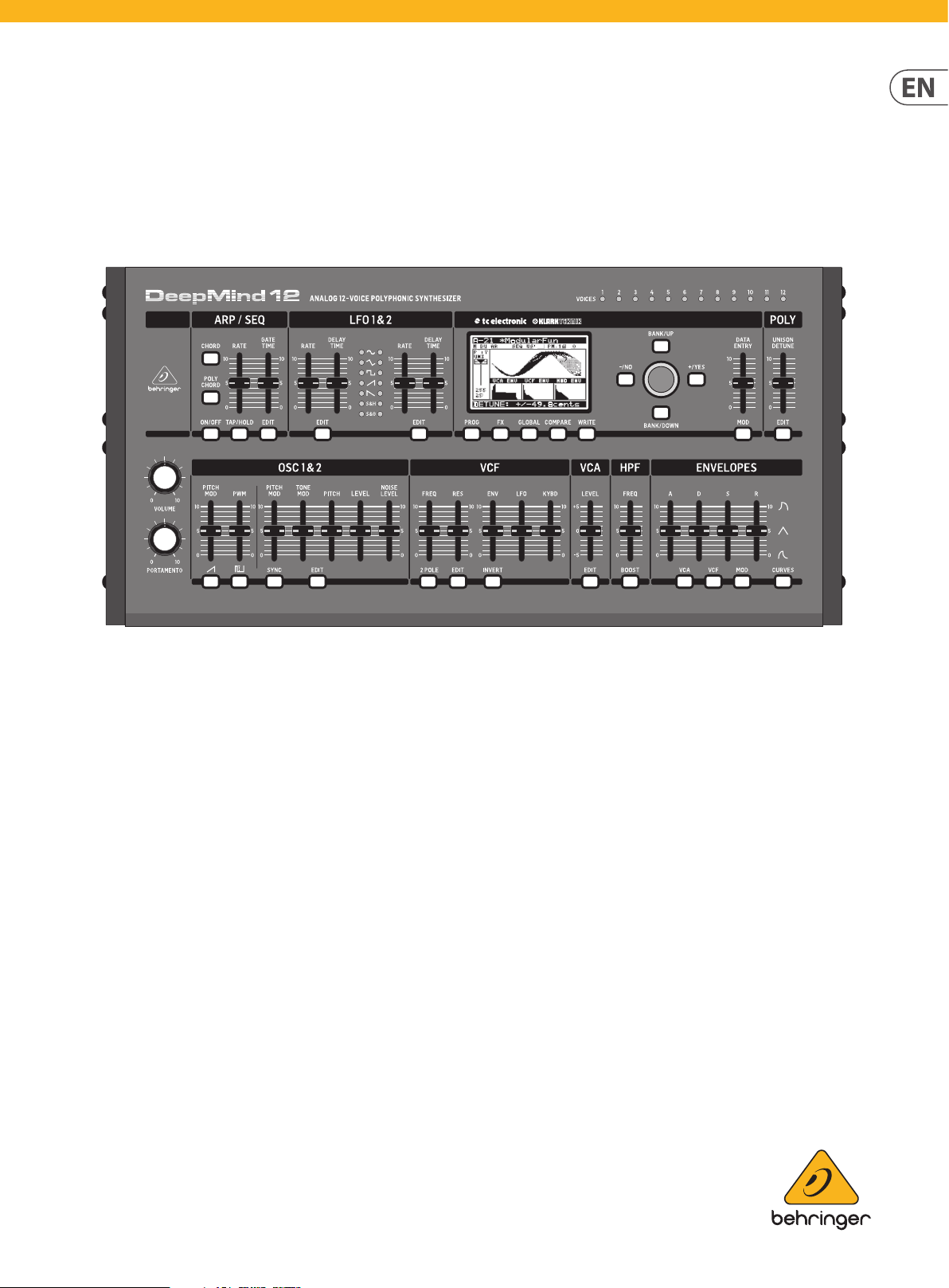
3. Controls
3.1 Top Controls
(15)
(14)
(5) (6)
(7) (9)
(1) (3) (2) (4) (8)
(13)
(10) (11) (12)
(1) DISPLAY - this large backlit LCD screen shows the synthesizer status,
parameters, and the ve main menus. The contrast and brightness are
adjustable on the PANEL SETTINGS page of the GLOBAL menu.
(2) NAVIGATION - navigate within the display menus using the UP, DOWN,
+/YES and -/NO buttons.
(3) MENUS - these switches allow access to the display menus.
PROG MENU- the main display of the synthesizer. Shows the current
program, the currently adjusted parameter and a visual representation of
the parameter and the three envelopes.
FX MENU - add up to four eects from the list available. Change the eects
routing by selecting one of the ten MODEs available. Each of the eects has
individual controls for all parameters.
GLOBAL MENU - view and adjust settings for the synthesizer. There are
four main pages: CONNECTIVITY, PEDAL, PANEL and SYSTEM.
COMPARE MENU - in this menu, you can compare the current program
with the stored program and see the dierence in physical fader positions.
WRITE MENU - in this menu, you can write the current program settings
to the program library. You can also rename the program and set its
category type.
(4) DATA ENTRY - selected parameters on the display are adjusted using the
rotary knob or the DATA ENTRY fader. The rotary knob has a click which
allows very accurate control. The fader allows rapid adjustment across the
full range.
MOD- this switch opens the modulation matrix on the display and allows
up to 8 modulations to be created from the list of sources and destinations.
(5) ARP/SEQ - this area controls the arpeggiator and the control sequencer.
ON/OFF - when activated, this generates an arpeggio based on pressed
keys. Note - the control sequencer is turned on from its edit page only.
RATE - adjusts the rate of the arpeggiator / sequencer in beats
per minute (BPM).
GATE TIME - adjusts the duration of the note played based on a
percentage of the time between triggered notes.
CHORD - allows you to play any chord with a single key. The chord is given
a root note and mapped across the keyboard.
POLY CHORD - allows you to play multiple chords from multiple keys.
The chords are mapped to individual keys.
TAP/HOLD - tap this button in time with your performance to set the
rate/BPM, or press and hold to engage the HOLD function.
EDIT - this allows additional arpeggiator/control sequencer parameters to
be edited from the main display.
Page 8

8 DeepMind 12D User Manual
(6) LFO 1 and 2- low frequency oscillators used to modulate or control
other parameters.
RATE- this sets the rate, or speed of the LFO.
DELAY TIME - the duration of time which will elapse before the
LFO starts.
EDIT - this allows additional LFO parameters to be edited from the
main display.
LFO WAVEFORMs - these LEDs indicate the type and status of the
waveforms produced by each LFO.
(7) OSC 1 & 2 - These analog full range oscillators create waveforms which
are the sound source of the synthesizer.
OSC 1 & 2 PITCH MOD - amount of pitch modulation applied to
respective OSC.
OSC 1 SQUAREWAVE- this switch turns the square wave output for
OSC 1 on/o.
OSC 1 PWM - amount of pulse width modulation applied to
the OSC 1 square wave.
OSC 1 SAWTOOTH- this switch turns the sawtooth output for
OSC 1 on/o.
OSC 2 TONE MOD- amount of tone modulation applied to OSC 2.
OSC 2 PITCH- controls the base pitch of OSC 2.
OSC 2 LEVEL- controls the level of OSC 2.
NOISE LEVEL- controls the amount of white noise added to the oscillators.
EDIT- this allows additional OSC parameters to be edited from
the main display.
(8) POLY - this area is used to control the polyphony of the synthesizer.
UNISON DETUNE - when voices are playing in unison, this adjusts the
amount of detuning between the voices.
EDIT - allows additional VCF parameters to be edited from
the main display.
ENV - adjusts the level of the VCF ENVELOPE which controls the
lter cut-o frequency.
INVERT - used to invert the polarity of the VCF envelope applied to the
lter cut-o frequency.
LFO - adjusts the depth of the selected LFO waveform applied to the lter
cut-o frequency.
KYBD - adjusts the amount of keyboard tracking to be applied to the lter
cut-o frequency.
(10) VCA - the voltage controlled amplier used to control the output level.
LEVEL - controls the output level of the VCA.
EDIT - this allows additional VCA parameters to be edited from
the main display.
(11) HPF - the voltage controlled high pass lter used to lter low frequencies
from the sound of the synthesizer.
FREQ - used to adjust the frequency of the high pass lter.
BOOST - this switch applies a +12 dB bass boost to the signal path
(12) ENVELOPE - these are the three envelopes used to modulate
other parameters.
A [ATTACK]- controls the attack time of the envelope.
D [DECAY] - controls the decay time of the envelope.
S [SUSTAIN] - controls the sustain level of the envelope.
R [RELEASE] - controls the release time of the envelope.
VCA - selects the envelope used to control the voltage controlled amplier.
VCF - selects the envelope used to control the voltage controlled lter.
MOD - selects the envelope used for user specic modulation.
EDIT- this allows additional POLY parameters to be edited from
the main display.
(9) VCF - the voltage controlled low pass lter used to lter high frequencies
from the sound of the synthesizer.
FREQ - adjusts the cut-o frequency of the lter.
2-POLE - changes the roll o slope of the lter from the default 4-POLE
mode to a 2-POLE mode.
RES - adjusts the resonance of the lter cut-o point.
CURVES - changes the ADSR controls to aect the associated curves for
each stage of the envelope.
(13) VOICES - these LEDs show which voices are active as keys are played.
(14) PORTAMENTO - changes the slide time between played notes.
(15) VOLUME - controls the output level of the synthesizer.
Page 9
9 DeepMind 12D User Manual
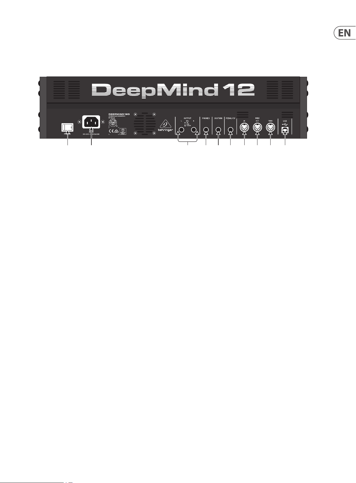
3.2 Rear Panel
(16) (17)
(16) POWER SWITCH - use this to turn the synthesizer on and o. Only turn it
on after all connections have been made.
(17) POWER INPUT - connect using the supplied power cable only.
(18) OUTPUT L / R - this is the main output of the synthesizer. It should be
connected to your audio interface or sound system. Remember to turn your
monitors / loudspeakers on last when turning on your system and turn
your monitors / loudspeakers o rst when turning your system o.
(19) PHONES - the headphones output of the synthesizer follows the main
output. Connect your headphones here. Ensure the volume control is at
minimum when putting on headphones or when turning the synthesizer
on or o.
(20) SUSTAIN - this ¼" TS jack allows you to connect a sustain pedal, such as a
normally-open switch.
The operation of this pedal can be customized using the GLOBAL /
PEDAL SETTINGS menu.
(21) PEDAL/C V - this ¼" TRS jack allows you to connect an expression pedal.
The operation of this pedal can be customized using the GLOBAL / PEDAL
SETTINGS menu.
(18) (19) (20) (21) (22) (23) (24) (25)
This will commonly be an external hardware sequencer, a computer
equipped with a MIDI inter face, etc.
(23) MIDI OUT - this 5-pin DIN jack sends MIDI data to an external source.
This will commonly be an external hardware sequencer, a computer
equipped with a MIDI inter face, etc.
(24) MIDI THRU - this 5-pin DIN jack is used to pass through MIDI data received
at the MIDI INPUT. This will commonly be sent to another synthesizer or
drum machine assigned to a dierent DEVICE ID, or MIDI Channel.
(25) USB PORT - this USB type B jack allows connection to a computer.
The DeepMind 12D will show up as a class-compliant USB MIDI device,
capable of supporting MIDI in and out. The DeepMind 12D does not
require any additional drivers to work with Windows, Android, MacOS
and iOS devices.
USB MIDI IN - accepts incoming MIDI data from an application.
USB MIDI OUT - sends MIDI data to an application.
(22) MIDI IN - this 5-pin DIN jack receives MIDI data from an external source.
Page 10
10 DeepMind 12D User Manual
4. Program Management
This chapter covers the program management for the DeepMind 12D analog
polyphonic synthesizer. It is important to understand how to manage your
programs and maintain your library.
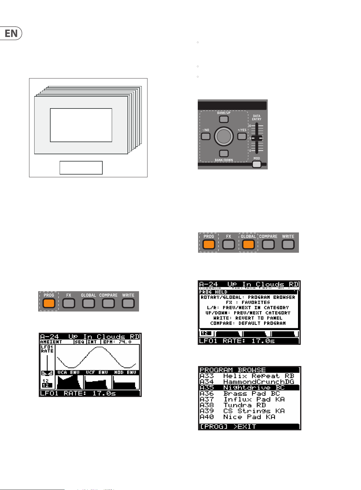
4.1 Program Library
Banks A-H
Programs 1-128
Editing Memory
The DeepMind 12D contains a total of 1024 programs. There are 8 Banks (A-H) of
128 programs. All programs can be overwritten as required; please consult the
chapter on restoring factory defaults if you need to return the DeepMind 12D
program library to its original state.
All current changes from the stored program are stored in temporary “Editing
Memory”. The changes are also placed into “Backup Memory” which can be used
to recover unsaved programs.
3. There are three methods of changing the current program:
• Step forwards/backwards through programs using the -/NO and+/YES
switches, or by stepping up and down through the banks using the
BANK/UP and BANK/DOWN switches.
• Using the program browser.
• From an external device using a MIDI program change message.
4.2.1 Using the Navigation Switches
1. Pressing -/NO or +/YES will load the previous/next program in the bank.
2. Pressing BANK/UP or BANK/DOWN will change banks.
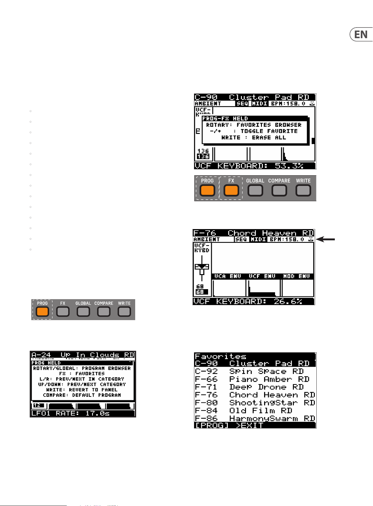
4.2.2 Using the Program Browser
1. To access the program browser, press and hold the PROG switch, then move
the rotary knob (or press the GLOBAL switch).
Note: The DeepMind 12D Programs are stored in EEPROM memory and will be
retained through a power cycle.
4.2 Selecting Programs
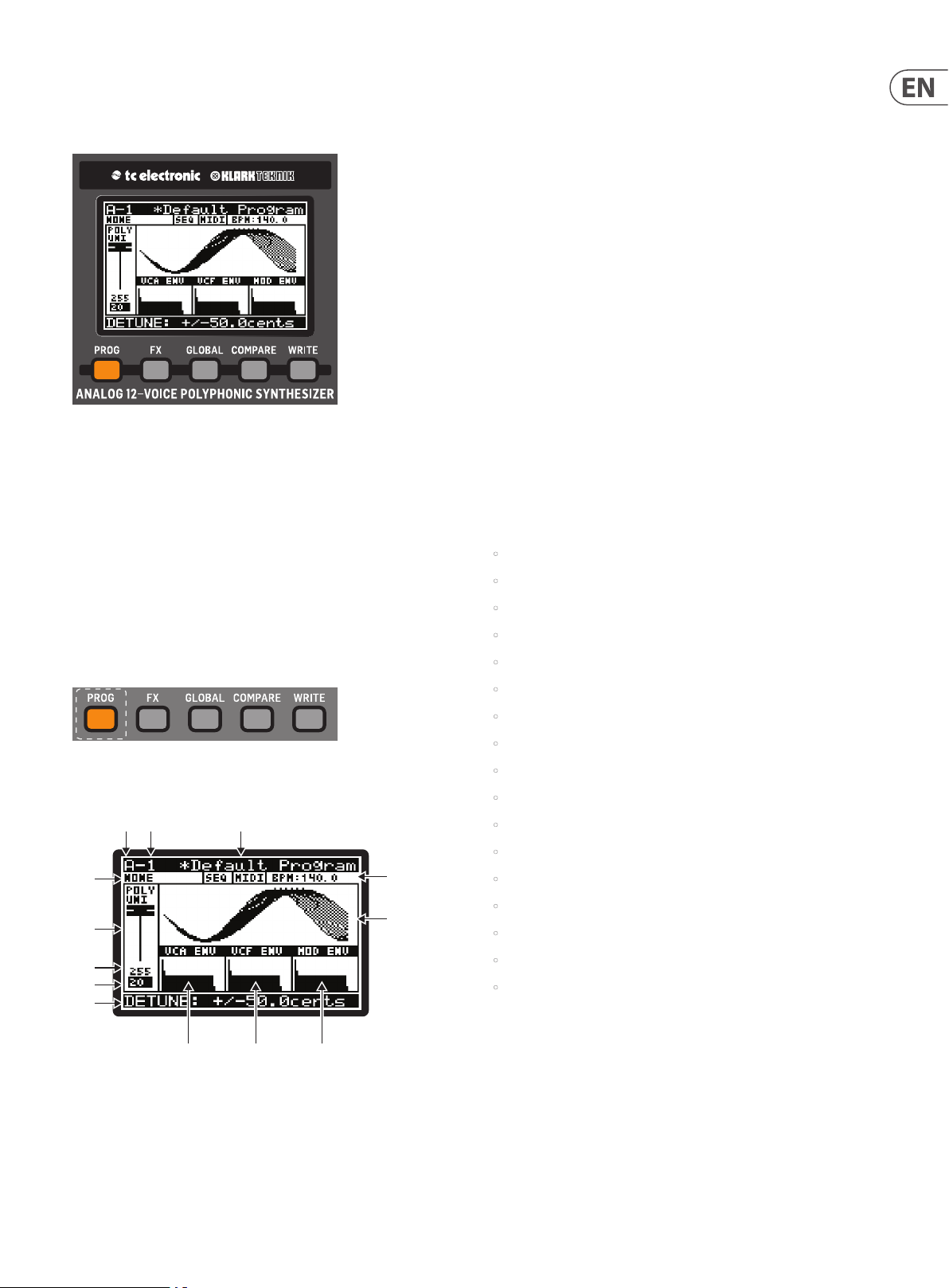
1. Press the PROG switch to open the PROG menu. This is also the screen which
will be displayed when the DeepMind 12D is turned on.
2. The PROG (Programming) page will be displayed:
The PROG (Programming) page is the main display of the synthesizer.
It shows the current program name, the category name, the currently
adjusted parameter and a visual representation of the parameter plus
the three envelopes.
Note: a “PROG HELD” help menu will appear while the PROG switch is held,
showing additional guidance and commands:
2. The program browser will then appear:
3. When in program browser mode, you can use the rotary knob to scroll
through the list of programs. When you stop on a program it will be
automatically loaded.
Page 11
11 DeepMind 12D User Manual
4.2.3 Using MIDI Program Change messages
You can change the program using a MIDI program change message. This special
MIDI message can be sent from your Digital Audio Workstation (DAW) or from
an external MIDI device which is capable of transmitting program change
messages, such as the BEHRINGER MOTOR 49/61 MIDI keyboard/controllers.
For details on the message please consult the section on MIDI commands.
4.3 Program Categories
Each program is assigned to a category from the list of options below:
• NONE - No category information is stored.
• BASS - Used for bass sounds.
• PAD - Used for pad sounds.
• LEAD - Used for lead sounds.
• MONO - Used for monophonic sounds.
• POLY - Used for polyphonic sounds.
• STAB - Used for stab sounds.
• SFX - Used for sound eects.
• ARP - Used for programs with the arpeggiator active.
• SEQ - Used for programs with sequencing.
• PERC - Used for percussion sounds.
• AMBIENT - Used for ambient or texture sounds.
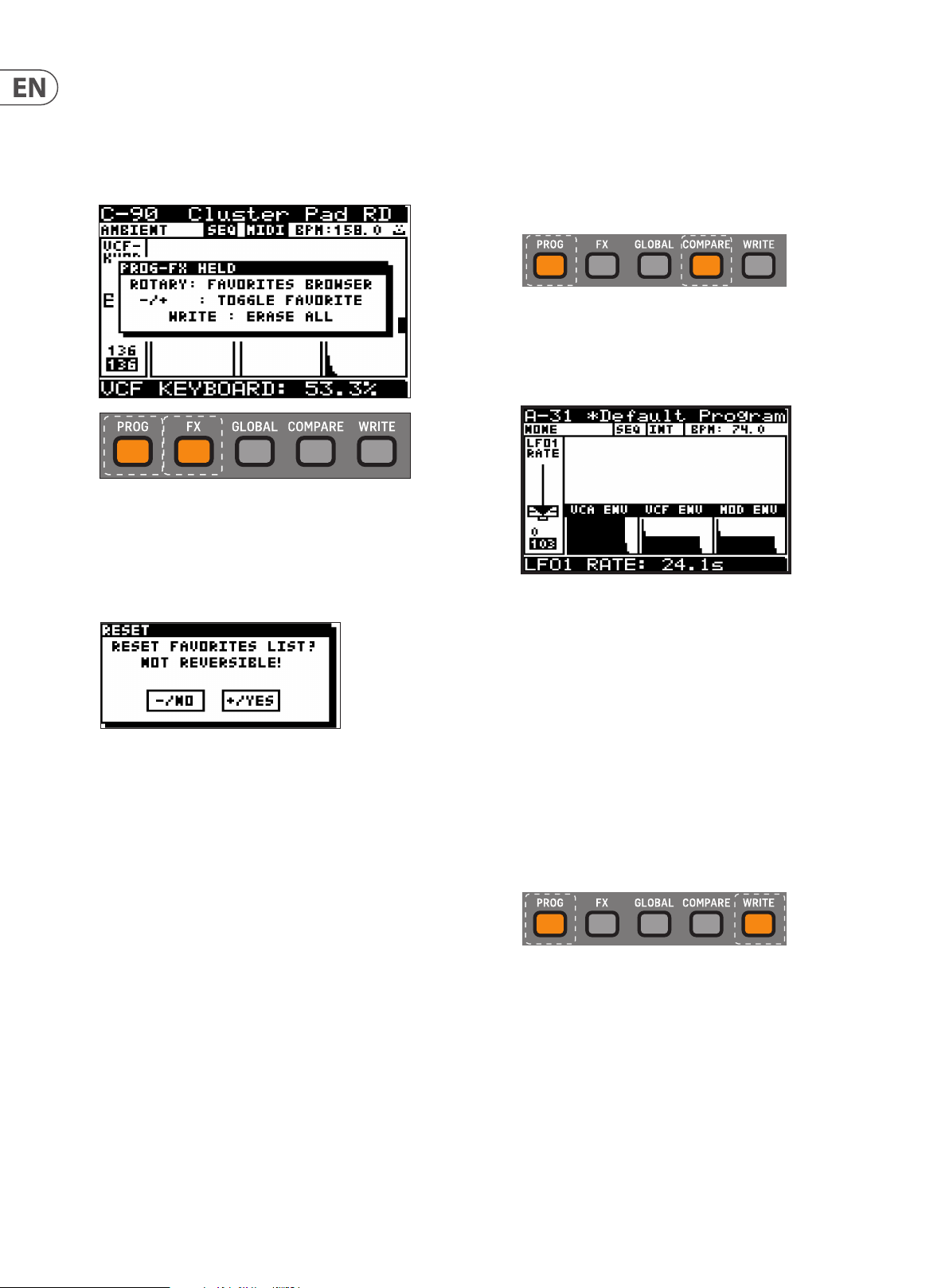
4.5 Favorites
You can create a list of favorite programs that can be recalled quickly, allowing
you to reach your favorite programs without having to scroll through all the
available programs.
Saving a Program as a Favorite
1. To save the current program as a favorite, press and hold the PROG and FX
switches at the same time, then press the +/YES switch.
2. A “happy face” icon will appear in the top right of the status line, and this
will appear in all programs that have been set as favorites.
• MODULAR -Used for programs with modular type programming.
• USER-1/4 - Used for user/project specic sounds.
The category is shown in the top left corner of the Prog display. For information
on how to assign a category, please consult section 4.9 on writing programs.
4.4 Browsing by Category
1. To access the program browser, press and hold the PROG switch.
Note: The PROG HELD help will appear while the PROG switch is held,
showing additional guidance and commands:
Recalling a Favorite Program
3. To recall a favorite, press and hold the PROG and FX switches at the same
time, and turn the rotary knob to navigate up and down the favorites list.
When you reach the favorite you want, it will be automatically loaded.
2. To change programs to others in the same category as the current program:
With the PROG switch held down, press the -/NO or +/YES switches to select
the previous or next programs within the same category.
3. To change to a dierent category: With the PROG switch held down, press
the BANK/UP or BANK/DOWN switches to select the previous or next
category. (Then, with the PROG switch still held down, you can use the -/NO
or +/YES switches to change programs within this new category.)
Page 12
12 DeepMind 12D User Manual
Deleting a Favorite
4. A favorite program will show the happy face icon in the upper right.
To delete it as a favorite, press and hold the PROG and FX switches at the
same time, then press the -/NO switch. The icon will disappear and the
program will no longer be in the favorites list. (The program itself is
not deleted.)
Deleting All Favorites
5. To empty the entire contents of the favorites list, press and hold the PROG
and FX switches at the same time, and then press the WRITE switch. After a
warning/conrmation message, all favorites will be removed from the list if
you press the +/YES switch. (The programs themselves are not deleted.)
4.6 Default Program
In order to return to a xed point when creating programs, you can recall a
default program using the shortcut described here. The default program is
congured without modulation/eects and uses basic settings in each of
the sections. (See Appendix 4 for more details.)
1. To load the default program, press and hold the PROG switch, then press the
COMPARE switch.
Note: The PROG HELD help menu will appear while the PROG switch is held,
showing additional guidance and commands.
2. The default program will then be loaded and the program name will change
to “*Default Program.”
Note: The “*” next to the program name is a reminder that something has
changed in the current program. Use the WRITE command to save this before
you change to a dierent program. See section 4.9 Writing Programs below
for more details.
4.7 Revert to Panel
When you load a program, all the physical controls on the DeepMind 12D may not
match the position stored in memory. In order to send all the physical positions
to the program (rather than moving each individually until you reach the
stored value), follow the procedure below:
Note: If you do this, the sound/character of the program will often change
radically as the multiple parameters are updated.
1. To revert to the panel controls, press and hold the PROG switch, then press
the WRITE switch.
Note: The PROG HELD help menu will appear while the PROG switch is held,
showing additional guidance and commands.
2. The current program will then be updated with the positions of the physical
controls on the DeepMind 12D.
Note: The “*” next to the program name is a reminder that something has
changed in the current program. Use the WRITE command to save this before
you change to a dierent program. See section 4.9 Writing Programs below
for more details.
Page 13
13 DeepMind 12D User Manual
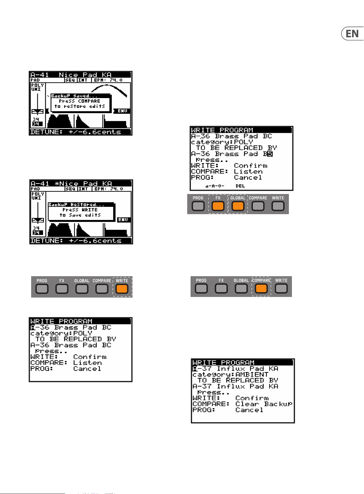
4.8 Restoring Program Data
1. If you edit a program and forget to write it before selecting a new program,
- don't panic - a backup of the program is stored in memory. Whenever this
happens a pop-up menu will appear with a message saying "Press COMPARE
to restore edits":
2. By pressing the COMPARE switch your previous editing patch will be
re-instated.
3. You will then see another pop-up message reminding you to press WRITE to
store your edits. See 4.9 Writing Programs below for more details.
5. The second section is the "CATEGORY" where you can select any of the
available program categories. Again you can use the BANK/UP, BANK/DOWN
switches, the rotary knob, or the fader to select the required category.
6. The third section is "TO BE REPLACED BY" which shows the name of the
program to be written. If you want to change the name, you can use the
-/NO or +/YES switches to step through each character of the name and
use the BANK/UP, BANK/DOWN switches, the rotary knob, or the faders to
change the character.
7. There are also two short-cuts for selecting characters, indicated by text in
bottom of the display, just above the FX and GLOBAL switches.
Note: These two short-cuts only appear when you are editing the name of
the TO BE REPLACED BY program.
4.9 Writing Programs
1. To write a program to memory, press the WRITE switch at any time.
2. The WRITE PROGRAM menu will then appear:
3. In this menu you can use the -/NO or +/YES switches to navigate through
the sections. The selected sec tion will be highlighted by an inverted
character (white on black).
a-A-0 - Press the FX switch to cycle between lower-case, upper-case, and
numbers/special characters.
DEL - Press the GLOBAL switch to delete the currently selected character.
8. To compare the current program with the intended program location, you
can press the COMPARE switch to listen to the dierence. To return to the
current program, press the COMPARE switch again.
9. Once you have selected the new location and named the program, press the
WRITE switch again to write the program.
At any time you decide not to write the program, press the PROG switch to
return to the main programming display.
Note: If there is a program in the backup memory (such as an unsaved
edited program), then you will see the message "COMPARE: Clear Backup".
4. The rst section is the program location where the current program will
be saved. You can use the BANK/UP, BANK/DOWN switches, the rotary knob,
or the DATA ENTRY fader to select the required BANK (A-H) and PROGRAM
NUMBER (1-128). Be careful that you do not overwrite an existing program
you would rather keep.
10. If you wish to listen to the intended program location as described earlier,
you will need to press the COMPARE switch to rst clear the backup
memory. Once the backup has been cleared then the message will
revert to "COMPARE: Listen" and you can listen to the intended program
location as normal.
Page 14
14 DeepMind 12D User Manual
4.10 Renaming Programs
1. To rename an existing program, follow the procedure above for writing a
program, keep the BANK and PROGRAM NUMBER the same, and then change
the name shown in the "TO BE REPLACED BY" section.
4.11 The COMPARE function
The COMPARE feature has two main functions:
• Firstly you can use it to COMPARE the current (edited) program with the
original program.
• Secondly you can use it to COMPARE and/or match the current position of the
physical faders on the surface with the original program. This is necessary
when you wish to maintain the sound/character of the program.
1. To perform both functions, press the COMPARE switch.
2. You will then see a page of the COMPARE menu. The page shown will be the
last page you used. If you have not used the COMPARE function since turning
the DeepMind 12D on, it will default to page 1 (shown below).
• If you have edited the program (i.e. changed some parameters), when
you press the COMPARE switch, you will restore the original stored
program so you can compare your edits to the original sound. Press
COMPARE again if you want to return to the edited version. Repeat this
to quickly compare the original and edited versions.
• In the COMPARE menu, you have the option to match the current
position of the faders to the positions stored in the original program.
If you do not want to match the fader positions, press COMPARE again to
return to your edited program.
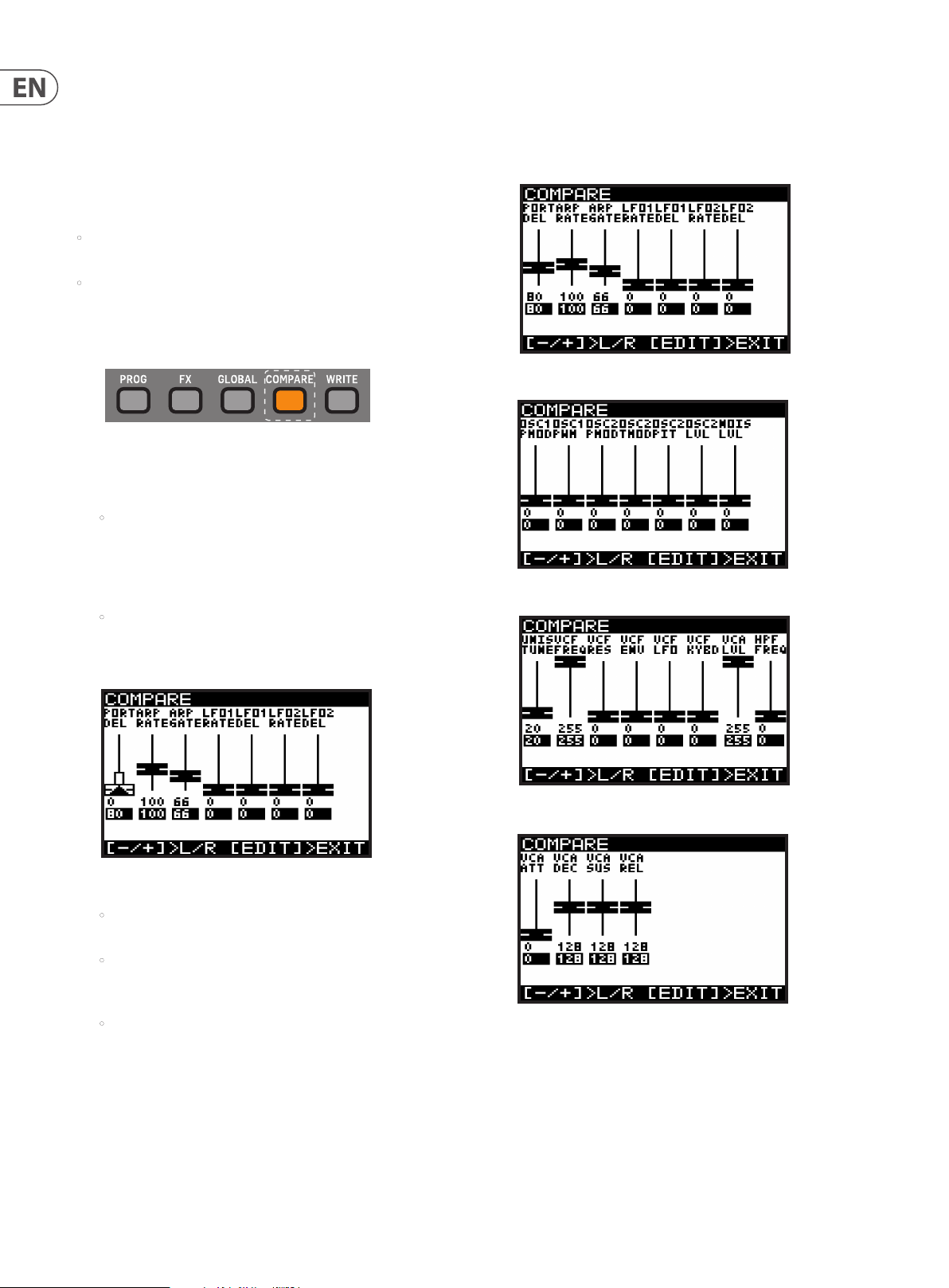
5. There are four pages of faders in the COMPARE menu, use the -/NO or +/YES
switches to selec t the previous or next pages, or just move a fader and its
COMPARE page will appear automatically.
Page 1 shows the ARP/SEQ and LFO faders. (The Portamento rotary knob is
represented by the rst fader on the left.)
Page 2 shows the OSC faders:
Page 3 shows the UNISON, VCF, HPF and VCA faders:
3. Each page of the COMPARE menu shows a section of the faders.
• If the position of the fader matches the position of the stored value, the
fader will be black.
• If the fader does not match the position it will be white with a
superimposed arrow pointing in the direction it needs to move in order
to approach the stored value.
• There is also a narrow white bar to show how far the fader needs to
move in order to match the stored value.
4. If you adjust a fader until it reaches the stored position, it will turn black to
indicate it is now matched.
Page 4 shows the ENVELOPE faders:
Note: You can still select specic envelopes to match the faders, depending
on your requirements.
6. Press COMPARE again to exit the COMPARE menus at any time and return to
the PROG menu.
Page 15
15 DeepMind 12D User Manual
5. Playing Guide
This section describes the use of the DeepMind 12D for playing and performance.
It covers all the main aspects of the synthesizer.
There are 60 physical controls on the DeepMind 12D, made up of illuminated
switches, faders, and rotary knobs.
There are also many virtual controls/parameters and menu-based controls
within the software; please consult the section on programming for
detailed information.
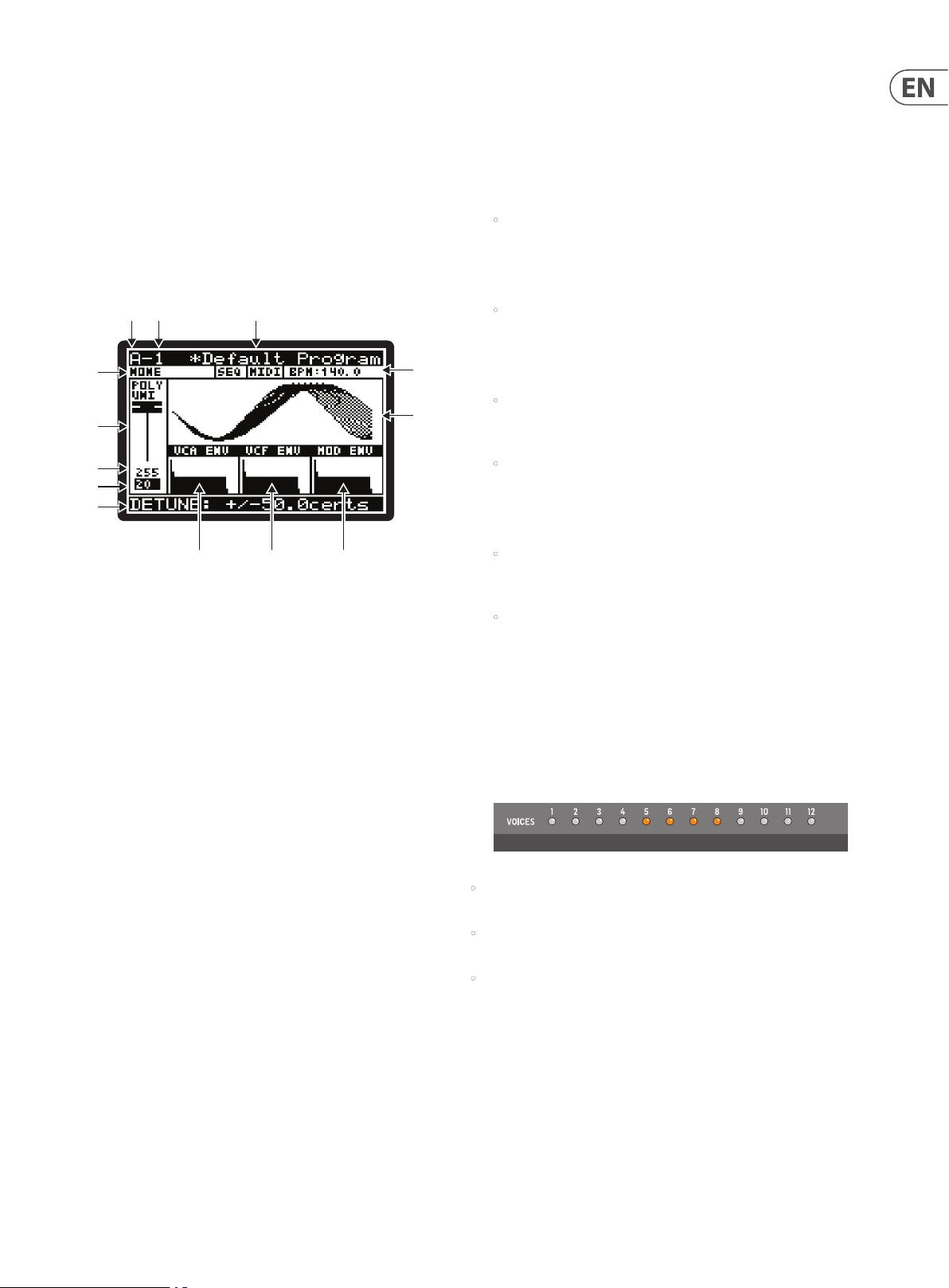
5.1 Display Overview
(2) (3)
(1)
(4)
(6)
(7)
(8)
(9)
(5)
(10)
5.2 Using a MIDI Keyboard Controller
The DeepMind 12D can be used with an ex ternal MIDI keyboard controller, and
depending on the capabilities of the controller, it may be able to transmit the
following MIDI information to the DeepMind 12D:
1. Transmit Velocity information to the DeepMind 12D - This is the speed at
which a key is pressed on or o.
• Note On and Note O Velocity can be used as a modulation source in the
MOD MATRIX section to aect many of the DeepMind 12D parameters.
2. Transmit Aftertouch information to the DeepMind 12D - This is the pressure
applied to a key as it is pressed.
• Pressure can be used as a modulation source in the MOD MATRIX section
to aect many of the DeepMind 12D parameters.
3. Apply Pitch Bend using a pitch wheel. This allows you to lower or raise the
pitch of the notes being played expressively.
• The range of the Pitch Bend can be assigned in the PITCH PARAMETERS
page of the POLY menu (accessed by pressing the POLY EDIT
switch twice).
• Pitch Bend can be used as a modulation source in the MOD MATRIX
section to aect many of the DeepMind 12D parameters.
4. Apply Modulation using a modulation wheel - This allows you to apply any
type of modulation or expression to single (or multiple) parameters.
(11) (12)
The PROG (Programming) page is the main display of the synthesizer.
During playing, the display can show the status of the synthesizer when the
PROG switch is pressed. The PROG switch will be illuminated when you are in
this mode.
Being able to see all this information on one screen allows you to quickly check
any of the following parameters shown on the display:
(1) PROGRAM BANK ("A "in the example above).
(2) PROGRAM NUMBER ("1" in the example above).
(3) PROGRAM NAME ("Default Program" in the example above.
(4) PROGRAM CATEGORY ("NONE" in the example above).
(5) SEQ STATUS / MASTER BPM EXTERNAL / BPM ( "OFF", "MIDI","140.0" in the
example above).
(6) PARAMETER CONTROL ("POLY UNI" in the example above).
(7) CURRENT PARAMETER MIDI VALUE (255 in the example above).
(8) STORED PARAMETER VALUE (20 in the example above).
(9) CURRENT PARAMETER EXPLICIT NAME/VALUE ( "DETUNE +/-50.0cents" in
the example above).
(13)
• For traditional playing this can be used to create vibrato, or in a
more creative way for example, to open the lter by assigning to the
VCF FREQUENCY.
• Modulation controlled by a modulation wheel can be used as a
modulation source in the MOD MATRIX section to aect many of the
DeepMind 12D parameters.
5. Octave Shift - This will allow you to raise or lower the ex ternal keyboard’s
pitch range in steps of one octave.
6. Program Change - This will allow you to change and selec t programs stored
in the DeepMind 12D using the external MIDI keyboard controller.
5.3 Voice Indication
• The DeepMind 12D has 12 independent voices. There are 12 LEDs at the top
right that show the status of each voice.
• When playing in traditional POLY mode, the voice LEDs will light individually
using the full polyphonic capabilities.
• When playing in any of the UNISON or MONO modes the voice LEDs will light
simultaneously depending on the number of voices allocated.
(10) PARAMETER VISUALIZATION (the UNISON waveform in the example above).
(11) VCA ENV VISUALIZATION (VCA ENV in the example above).
(12) VCF ENV VISUALIZATION (VCF ENV in the example above).
(13) MOD ENV VISUALIZATION (MOD ENV in the example above).
Note: The brightness and contrast of the display can be adjusted in the
GLOBAL-PANEL SETTINGS menu.
For more detail on the PROG screen and the status of the synthesizer, please
consult the programming section later in this manual.
Note: The settings to adjust the polyphony and voice allocation can be
found in the POLY-VOICE PARAMETERS menu.
Page 16
16 DeepMind 12D User Manual
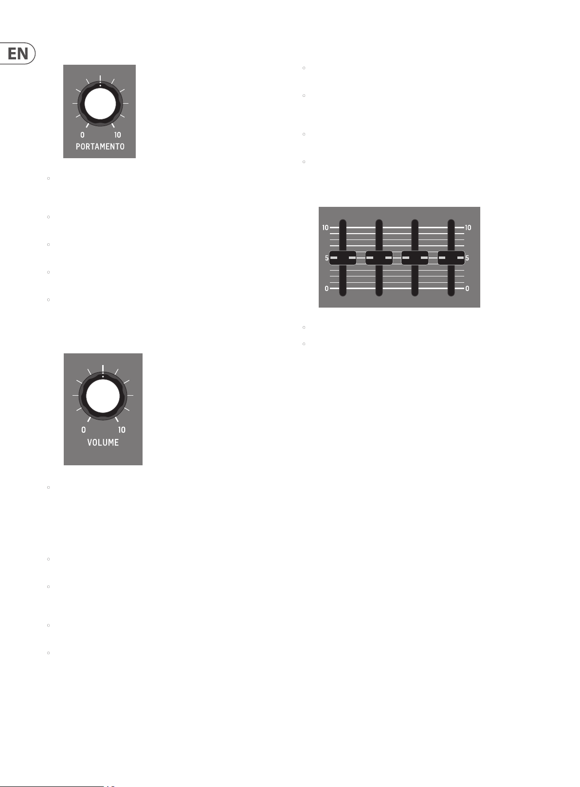
5.4 Portamento
• The PORTAMENTO function makes the pitch of a note glide up or down from
the previously played note. The PORTAMENTO knob controls the time taken
to transition from the previous note to the currently played note.
• The knob ranges from 0 seconds (instant change of note, with no
pitch gliding) to 10 seconds.
• The PORTAMENTO function can be tuned to your specic playing
requirements by way of 14 dierent modes.
• The PORTAMENTO function can also be balanced between the OSCs, allowing
you to set the ratio of PORTAMENTO applied to OSC 1 and OSC 2.
• For more detail on controlling advanced parameters relating to PORTAMENTO
please consult the section later in this manual. The PORTAMENTO options are
available in the POLY EDIT menu, PITCH PARAMETERS page.
5.7 Sustain Input (Rear Panel)
• The sustain input is a ¼" TS jack that allows you to connect a sustain pedal,
such as a normally-open switch.
• The sustain input can be assigned to operate in one of ten modes. For
more information please consult the PEDAL SETTINGS section later in
this document.
• The operation of this pedal can be customized using the GLOBAL / PEDAL
SETTINGS menu.
• For more detail on controlling advanced parameters relating to the sustain
input please consult the section later in this manual.
5.8 Slide Fader Operation Modes
• The slide faders can operate in two modes: PASS-THRU or JUMP.
5.5 Volume
• The volume knob controls the output level for both the main outputs
and the headphones simultaneously. If you nd the need to compensate
the main output level, please do so using your gain stage on your mixer,
audio interface or amplier.
5.6 Pedal Input (Rear Panel)
• The pedal input is a ¼" TRS jack that allows you to connect an
expression pedal.
• The pedal input can be assigned to operate in one of seven modes:
FOOT CONTROL, MOD WHEEL, BREATH, VOLUME, EXPRESSION, PORTA TIME,
and AFTERTOUCH.
• The operation of this pedal can be customized using the GLOBAL /
PEDAL SETTINGS menu.
• For more detail on controlling the way the slide faders respond when
adjusted, please consult the section later in this manual.
Note: You can also turn o the fader LOCAL messages allowing you to
control an external device, without aecting the DeepMind 12D.
• For more detail on controlling advanced parameters relating to the pedal
input please consult the section later in this manual.
Page 17
17 DeepMind 12D User Manual
HPF BOOST
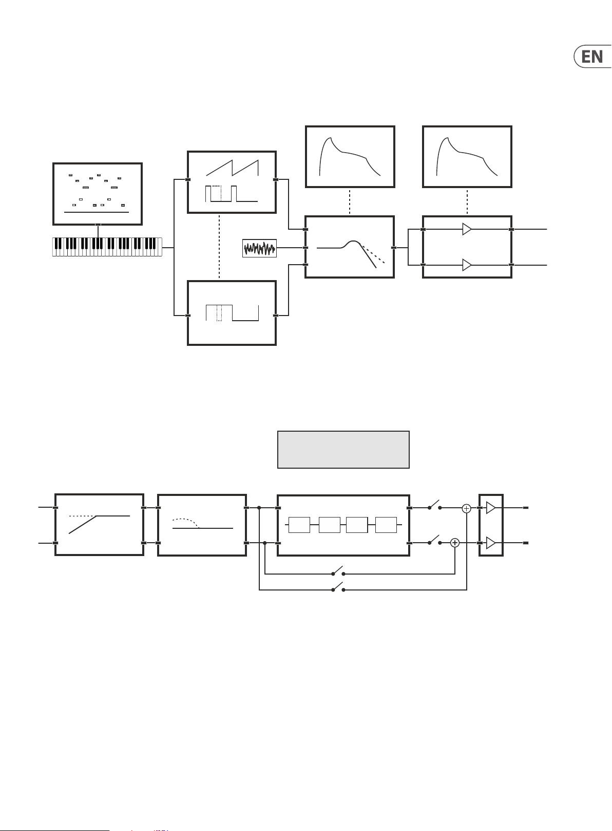
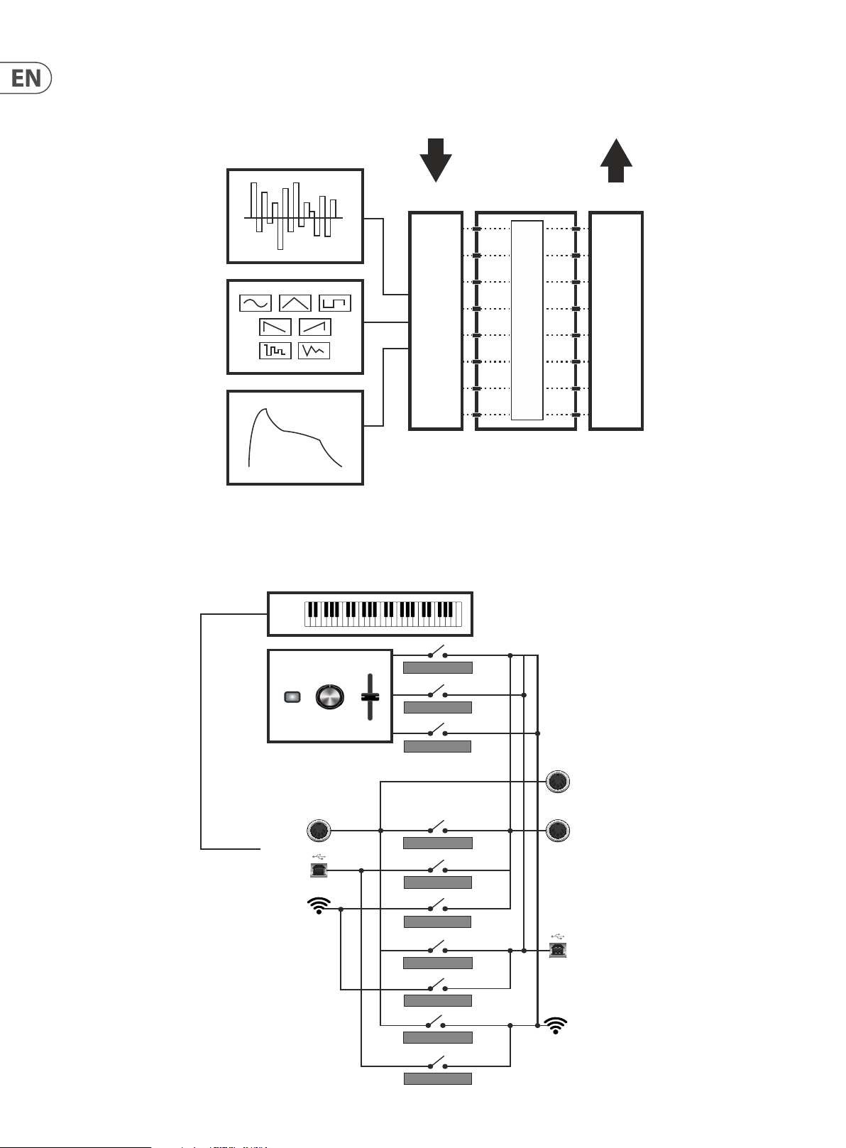
6. Signal Path / Voice Structure
The signal path / voice struc ture from the OSCs to the main outputs is completely analog. The DSP eects can be bypassed completely to maintain the analog path.
When routed through the DSP eects, all sampling is done at 24-Bit 48 kHz. All internal DSP eects are processed at 32/40-Bit oating point resolution.
VCF Env VCA Env
OSC-1
Arpeggiator
Key Pitch
(External MIDI keyboard)
HPF BOOST
OSC-2
Noise
BYPASS
FX
MODE
INSERT
SEND
VCF
ANALOG PATH
OFF
ON
ON
DIGITAL PATH
ON
ON
OFF
VCA
DIGITAL PATH
Volume
1 2 3 4
ANALOG PATH
Main Outputs &
Headphones
Page 18
18 DeepMind 12D User Manual
SOFT-THRUSOFT-THRU
MIDI>USB-THRU
MIDI>WIFI-THRU
USB>MIDI-THRU
USB>WIFI-THRU
WIFI>MIDI-THRU
WIFI>USB-THRU
External Keyboard Data
Control Data
Wi-Fi
USB
MIDI IN
Wi-Fi
USB
MIDI THRU
MIDI OUT
SOFT-THRUMIDI-CTRL
USB-CTRL
WIFI-CTRL
Mod Matrix
The Modulation Matrix is a large scale digital routing matrix which allows a massive number of potential modulations. The matrix conguration is stored and recalled
with the program data.
Control Sequencer
Modulation
Destinations
130 DESTINATIONS
LFO1&2
MOD Env
Modulation
Sources
22 SOURCES
22,880 Possible Modulations (All Automatable)
8x8 Mod Matrix
ROUTING LEVELS
MIDI Routing
The DeepMind 12D oers extreme MIDI routing possibilities, allowing you to integrate the synthesizer with many dierent pieces of hardware and software.
Page 19
19 DeepMind 12D User Manual
7. Menu System
The DeepMind 12D Display allows you to access the detailed parameters,
controls, options, and features of the synthesizer.
Navigating the MENU system can be done by pressing the top level menu
switches PROG, FX, GLOBAL, COMPARE and WRITE.
The FX and GLOBAL menus have several pages; to access successive pages, simply
press the same switch again to cycle through the pages.
The DeepMind 12D will always return you to the last page within a menu that
was accessed. This way you can return to your last change without needing to
cycle though the previous pages. Note: You can change this functionality using
the REMEMBER PAGES option in the GLOBAL SETTINGS.
7.1 PROG (Programming Menu)
To access the PROG menu, press the PROG switch and it will remain illuminated
while you are in this menu.
7.1.1 PROGRAM BANK
(1) ("A "in the example diagram) - There are 8 BANKS of PROGRAMs, each BANK
contains 128 program locations. The DeepMind 12D comes pre-loaded
with 1024 programs from leading synthesizer programmers from around
the world.
7.1.2 PROGRAM NUMBER
(2) ("1" in the example diagram) - There are 128 PROGRAMs in each BANK.
7.1.3 PROGRAM NAME
(3) ("Default Program" in the example diagram) - The PROGRAM name can use
up to 16 characters, including uppercase, lowercase, numbers and symbols.
Note: When you see the '*' symbol at the start of a PROGRAM name this
indicates that the PROGRAM has been edited/changed from its stored state.
Once you complete your editing and WRITE the program, the '*' symbol will
no longer be shown.
7.1.4 PROGRAM CATEGORY
(4) ("NONE" in the example diagram) - Each PROGRAM can be assigned to one of
17 categories. By assigning a category to a PROGRAM, it helps browsing for a
particular type of sound much easier.
The available categories are listed here:
• NONE - No category information is stored.
• BASS - Used for bass sounds.
• PAD - Used for pad sounds.
• LEAD - Used for lead sounds.
• MONO - Used for monophonic sounds.
• POLY - Used for polyphonic sounds.
The PROG menu will then be shown:
(2) (3)
(1)
(4)
(6)
(5)
(10)
(7)
(8)
(9)
(11) (12)
The PROG page is the main display of the synthesizer.
While playing, the display can show the status of the synthesizer when the PROG
switch is pressed. It always changes whenever a control is adjusted.
Being able to see all this information on one screen allows you to quickly check
any of the following parameters shown on the display:
(13)
• STAB - Used for stab sounds.
• SFX - Used for sound eects.
• ARP - Used for programs with the arpeggiator active.
• SEQ - Used for programs with sequencing.
• PERC - Used for percussion sounds.
• AMBIENT - Used for ambient or texture sounds.
• MODULAR -Used for programs with modular type programming.
• USER-1 - Used for user/project specic sounds.
• USER-2 - Used for user/project specic sounds.
• USER-3 - Used for user/project specic sounds.
• USER-4 - Used for user/project specic sounds.
For information on how to assign a category, please consult the section on
writing programs.
Note: The User-1, User-2, User-3, and User-4 categories will only appear in
the list of categories when the WRITE function has been used to previously
store programs into these categories.
Page 20
20 DeepMind 12D User Manual
7.1.5 SEQ STATUS, MIDI SYNC SOURCE, BPM VALUE
(5) It is important to note that on this line there are four separate pieces
of information:
• SEQ S TATUS ("SEQ" in the example diagram) - This shows the status of
the CONTROL SEQUENCER. If the letters SEQ are inverted (white on a black
background) then the CONTROL SEQUENCER is ON. If the let ters SEQ appear as
normal text the CONTROL SEQUENCER is OFF. Note: The CONTROL SEQUENCER
ON/OFF control can only be adjusted from the CONTROL SEQUENCER MENU
described later in this document.
• MASTER BPM SOURCE ("MIDI" in the example diagram) - The Master BPM
can be generated internally (shown as "INT"), or the DeepMind 12D can
synchronize to an incoming MIDI clock signal from the MIDI IN socket (shown
as "MIDI"), or USB ports (shown as "USB"). If the letters are inverted (white
on a black background) then the clock is synchronised to the external source.
If the letters appear as normal text the external source is not present and
the DeepMind 12D will use its internal Master BPM until the external source
is present. Note: The settings for the MIDI SYNC can be found in the EDIT
page of the ARPEGGIATOR described later in this document.
• BPM VALUE ("BPM:140.0" in the example diagram) - The Arpeggiator,
Control Sequencer and Patterns use a system-wide Master BPM (Beats
Per Minute) Clock. The BPM is shown and will auto update if using an
external synchronisation source.
• HAPPY FACE ICON This icon in the far right of the line shows that the current
program has been saved in the list of favorites (see section 4.5 Favorites).
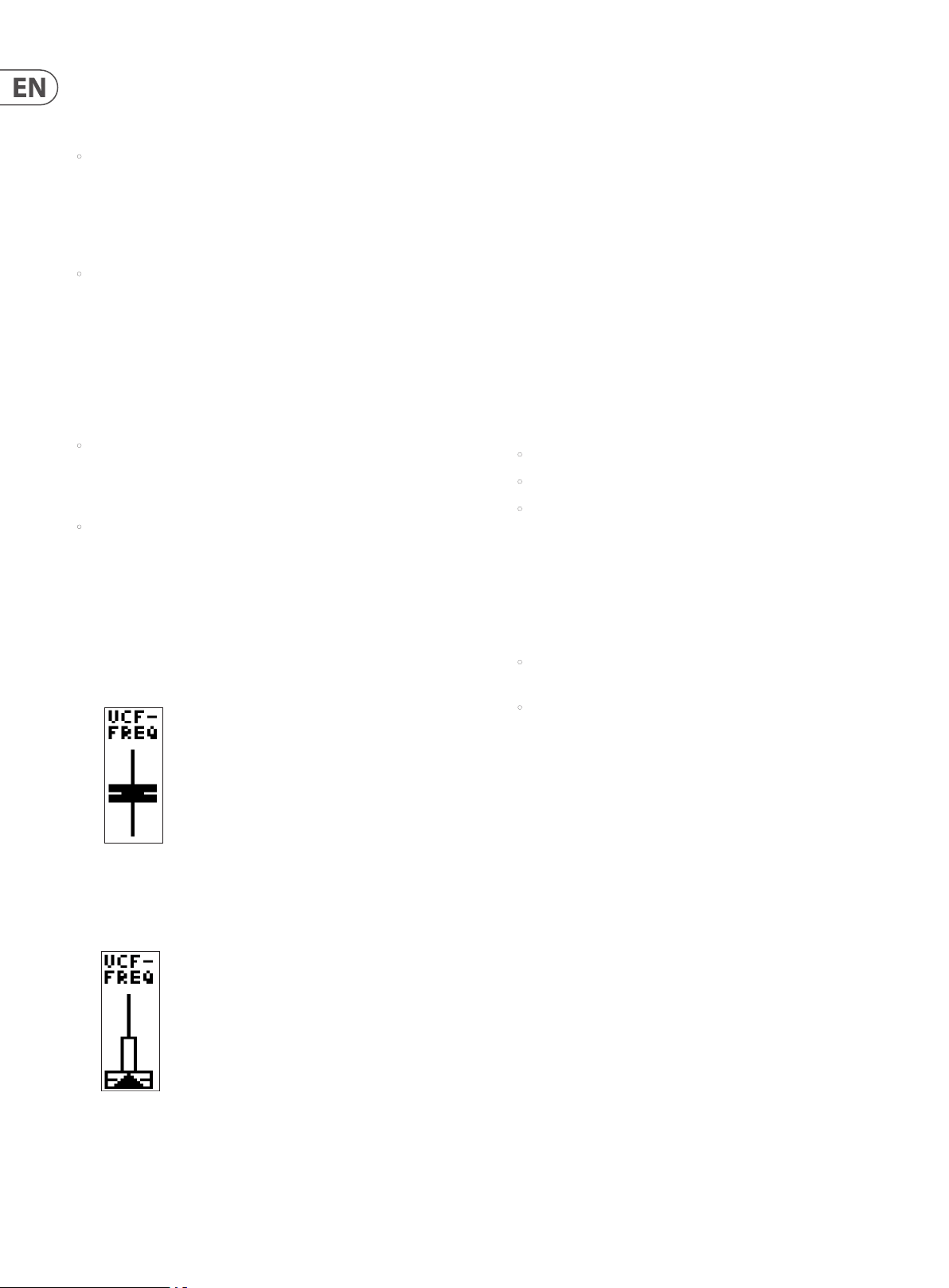
7.1.6 PARAMETER CONTROL
(6) ("POLY UNI" in the example diagram) - This is a fader representation of the
parameter which is currently being adjusted (or was last adjusted). The
name of the parameter is also shown:
If the position of the fader matches the position of the stored value, the fader
will be black.
7.1.7 CURRENT PARAMETER MIDI VALUE
(7) (255 in the example diagram) - This is the value of the parameter which is
currently being adjusted (or was last adjusted).
Note: The parameter is displayed here as a simple value (0-255) which
allows you to quickly compare current and stored values. For explicit values
please see the area at the bottom of the page discussed later in this chapter.
7.1.8 STORED PARAMETER VALUE
(8) (20 in the example diagram) - This is the stored value of the parameter
which is currently being adjusted (or was last adjusted).
The stored parameter is always shown in reverse text (i.e. white on a
black background)
7.1.9 CURRENT PARAMETER NAME/VALUE
(9) ("DETUNE +/-50.0cents" in the example diagram) - In this area you will see
more detailed information on the parameter being adjusted.
The enhanced information contains:
• A more detailed description of the parameter being adjusted.
• A more accurate value of the parameter being adjusted.
• The type of units used for the value (cents in the example above,
but could be Hz for frequency etc.).
7.1.10 PARAMETER VISUALIZATION
(10) (The UNISON waveform in the example diagram) - This area shows a
visualization of the parameter being adjusted (or last adjusted).
These visualizations are designed to:
• Help anyone with limited experience to achieve a deeper understanding
of each of the parameters while learning the synthesizer.
• Help the experienced player/sound designer/programmer to work
quickly and get visual conrmation about the adjustment being made.
If the fader does not match the position, it will be white with a
superimposed arrow pointing in the direction it needs to move in order to
approach the stored value. There is also a thin vertical white bar to show
how far the fader needs to move in order to match the stored value.
Note: If the physical fader position is close to the stored value the white bar
can be obscured by the fader.
7.1.11 VCA ENV VISUALIZATION
(11) (VCA ENV in the example diagram) - This area shows a visualization of the
VCA envelope. The full Attack, Decay, Sustain, Release and their respective
curves are represented.
7.1.12 VCF ENV VISUALIZATION
(12) (VCF ENV in the example diagram)- This area shows a visualization of the VCF
envelope. The full Attack, Decay, Sustain, Release and their respective curves
are represented.
7.1.13 MOD ENV VISUALIZATION
(13) (MOD ENV in the example diagram) - This area shows a visualization of the
MOD envelope. The full Attack, Decay, Sustain, Release and their respec tive
curves are represented.
Page 21
21 DeepMind 12D User Manual
7. 2 FX (Eects Menu)
The on-board vir tual FX Rack provides access to four true-stereo, multi-eects
processors including delay, chorus, dynamics and production-quality true-stereo
reverbs. You can select any combination of high-end simulations of legendary
studio eects.
Note: For detailed information on all eects and their parameters, please consult
the EFFECTS LIBRARY section later in this document.
7.2 .1 FX OVERVIEW
1. To access the FX menu press the FX switch: the FX switch will be illuminated
when you are in this menu.
2. The display will then show the FX OVERVIEW menu:
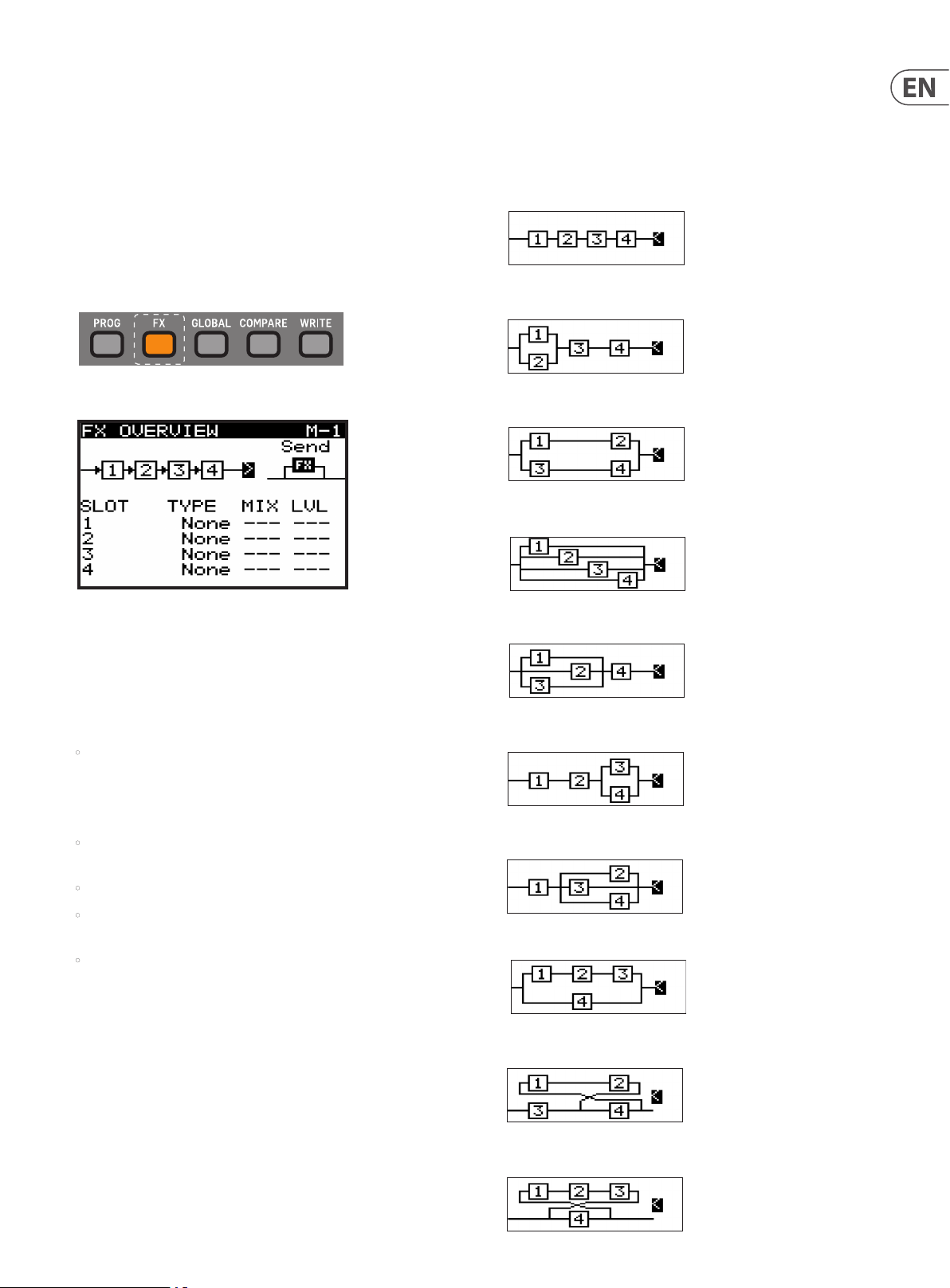
7.2.2 SELECTING FX ROUTING
1. To select a routing from the 10 dierent options, make sure that the '<'
symbol is highlighted next to the routing diagram, then you can either
turn the rotary knob, or use the data entry fader to select from one of the
following routings:
SERIAL 1-2-3-4 (M -1)
PARALLEL 1/2 SERIAL 3-4 (M-2)
PARALLEL 1/2 PARALLEL 3/4 (M-3)
PARALLEL 1/2/3/4 (M- 4)
3. To navigate within the items in the FX OVERVIEW menu, use the BANK/UP,
BANK/DOWN, +/YES, and -/NO switches.
4. Selected parameters on the display are adjusted using the rotary knob
or the DATA ENTRY fader. The rotary knob has a click which allows very
accurate control. The fader allows rapid adjustment across the full range.
5. The options available in the FX OVERVIEW menu are as follows:
• FX ROUTING - At the top of the FX OVERVIEW menu, the FX ROUTING is
shown as a series of 4 boxes representing the individual eects.
In order to expand the sonic possibilities of the DSP FX inside the
DeepMind 12D, there are 10 routing options for the four slots.
• FX MODE - This allows you to choose if the eects are to be congured
in INSERT MODE, SEND (and Return) MODE, or to BYPASS the eects.
• FX SLOTS - These are the four slots you can load eects modules into.
• MIX - The MIX parameter controls how much of the original sound is
blended with the eected/processed sound for each FX slot.
• LEVEL - The LEVEL parameter controls the output level of any eects
which are congured in parallel, or any eects which are the last eect
before reaching the output stage.
6. To exit the FX menu, press the PROG switch to return to the main
programming screen.
WARNING: The routings with feedback are highly creative, but as they employ
feedback loops, careful consideration should be made while using them. It is
recommended to keep the VOLUME knob in a low position while experimenting.
PARALLEL 1/2/3 SERIAL 4 (M-5)
SERIAL 1-2 PARALLEL 3/4 (M-6)
SERIAL 1 PARALLEL 2/3/4 (M-7)
PARALLEL (SERIAL 1-2-3)/4 (M-8)
SERIAL 3-4 FEEDBACK4(1-2) (M-9)
Note: To reduce the possibility of excessive low frequency build up, there is
a 30 Hz High Pass Filter used in the feedback path for routing options which
include feedback.
SERIAL 4 FEEDBACK4(1-2-3) (M-10)
Page 22
22 DeepMind 12D User Manual
7.2 .3 SELECTING FX MODE
1. To select an eects MODE, make sure that the '<' symbol is highlighted next
to the eects MODE symbol, then you can either turn the rotary knob, or use
the data entry fader to select from one of the following routings.
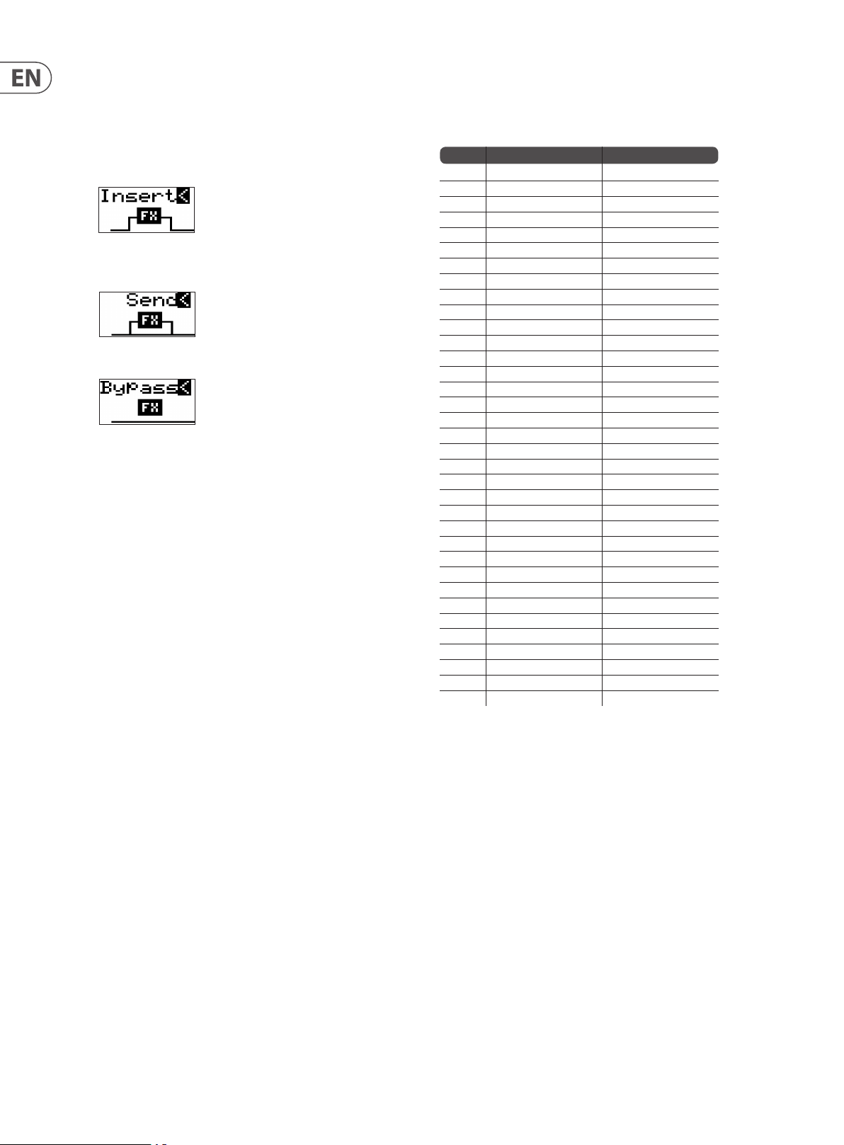
INSERT - In this conguration the eects slots are placed as INSERT eects
into the signal ow of the synthesizer outputs.
SEND - In this conguration the synthesizer output signals are SENT to the
eects slots and the returned into the signal ow of the synthesizer outputs.
BYPA SS - In this conguration the eects are bypassed.
7.2 .4 SELECTING FX
1. To load an eect into a slot, make sure that the '<' symbol is highlighted
next to the slot you wish to use. Then you can either turn the rotary knob, or
use the data entry fader to select from one of the following eec ts:
No Name Type
1 TC-DeepVRB Reverb
2 AmbVerb Reverb
3 Room Rev Reverb
4 VintageRev Reverb
5 Hall Rev Reverb
6 Chamber Rev Reverb
7 Plate Rev Reverb
8 Rich Plate Reverb
9 Gated Rev Reverb
10 Reverse Rev Reverb
11 ChorusVerb Reverb
12 D elayVerb Reverb
13 FlangeVerb Reverb
14 Midas EQ Processing
15 Enhancer Processing
16 FairComp Processing
17 MulBndDist Processing
18 RackAmp Processing
19 EdisonEX1 Processing
20 Auto-Pan Processing
21 NoiseGate Processing
22 Delay Delay
23 3Tap Delay Delay
24 4TapDelay Delay
25 T-RayDelay Delay
26 DecimDelay Delay
27 ModDlyRev Delay
28 Chorus Creative
29 Chorus-D Creative
30 Flanger Creative
31 Phaser Creative
32 MoodFilter Creative
33 DualPitch Creative
34 Vintage Pitch Creative
35 Rotar ySpkr Creative
2.
When you stop on an eect, it is automatically loaded into the chosen slot.
7.2 .5 CONTROLLING MIX / LEVEL
1. To adjust the MIX parameters make sure that the '<' symbol is highlighted
next to the word MIX on the eect slot you want to adjust. Then you can
either turn the rotary knob, or use the data entry fader to change the value.
7.2 .6 CONTROLLING LEVEL
1. To adjust the LEVEL parameters, make sure that the '<' symbol is highlighted
next to the word LEVEL on the eect slot you want to adjust. Then you can
either turn the rotary knob, or use the data entry fader to change the value.
Note: The MIX parameter is not used on eects which are marked as
"Processing" types in the Eects List. Also, be aware that the MIX parameter
seen on the FX OVERVIEW, and the MIX parameter shown in the FX
editing pages, are the same parameter and are shown in both pages for
convenience.
2. If the MIX parameter or the LEVEL parameter are not available, you will see
the "--" symbols in the FX OVERVIEW screen.
Page 23
23 DeepMind 12D User Manual
7.2 .7 FX PAGES 1-4
1. To view the FX parameters, press the FX switch any time you are in the FX
OVERVIEW menu.
2. The rst page will show the parameters of the FX in the rst slot. There are
up to 12 parameters per FX, depending on the FX which is loaded.
3. Press the FX switch again to cycle through each of the FX currently present in
your program.
4. When you reach the last FX in your program, press FX once more to return to
the PROG display screen.
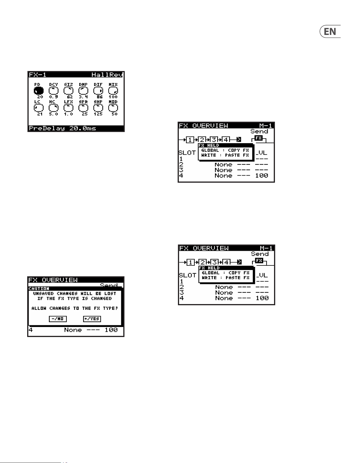
7.2 .8 ADJUSTING EFFECTS PARAMETERS
1. To navigate to the parameter you wish to adjust within an FX page, use the
BANK/UP, BANK/DOWN, +/YES, -/NO switches. The selected parameter will
be highlighted in black and its details shown on the bottom of the screen.
For example, in the FX-1 page shown above, the PD knob is highlighted, and
the full name and value are shown as "Pre Delay 20.0 ms."
2. To adjust a parameter, turn the rotary knob, or use the data entry slider.
3. When you are nished adjusting the parameters, and you would like to keep
them, press WRITE. If not, the changes will remain in operation until you try
to change the program, or change to a dierent FX in the same slot.
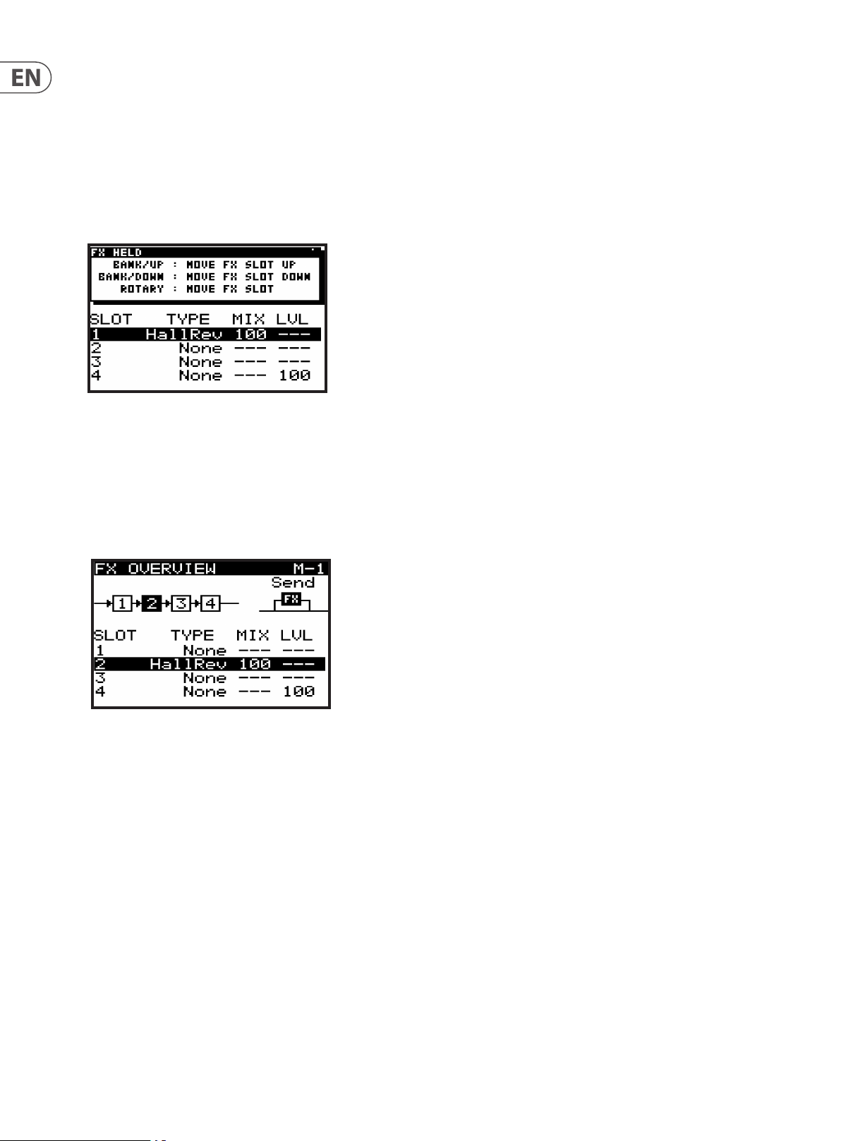
7.2 .9 COPY/PASTE FX SETTINGS
If you need to copy all 4 eects settings from one program to another, please
follow this procedure:
1. Ensure you have saved any edits you have made to your current program
if required.
2. Load the program which has the eects settings you intend to copy.
3. Press the FX switch to enter the FX OVERVIEW page. (You may have to press it
a few times, depending on which FX page it was on last.)
4. Navigate to the 1, 2, 3, 4 ow diagram near the top of the FX screen.
5. Press and hold the FX switch until you see the following message and the
GLOBAL and WRITE switches are ashing:
6. While continuing to hold the FX switch, press the GLOBAL switch to copy the
eects settings into memory.
7. Then load the program you intend to paste the eects settings to.
8. Press the FX switch to enter the FX OVERVIEW page.
9. Navigate to the 1, 2, 3, 4 ow diagram near the top of the FX screen.
10. Press and hold the FX switch until you see the following message:
4. Caution: If you try to change to a dierent FX in the same slot as an edited
(but unsaved) FX, then a CAUTION dialog will appear (unless dialogs are
disabled in the GLOBAL MENU):
5. If you need to save your changes, press the -/NO switch and then WRITE the
program as described in the chapter on writing programs.
6. If you don't need to save your changes, press the +/YES switch and continue
selecting a new eect. Your changes to the previous FX will be lost.
7. Press FX to move on to the next FX page.
8. On the last FX page, press FX again to return to the PROG menu.
11. While continuing to hold the FX switch, press the WRITE switch to copy the
eects settings from memory into the program.
Note: All settings relating to eects will be copied/pasted, these include FX
routing, FX modes and all of the FX slots and their set tings.
Note: The WRITE: PASTE FX option will only appear when something has
been previously copied.
Page 24
24 DeepMind 12D User Manual
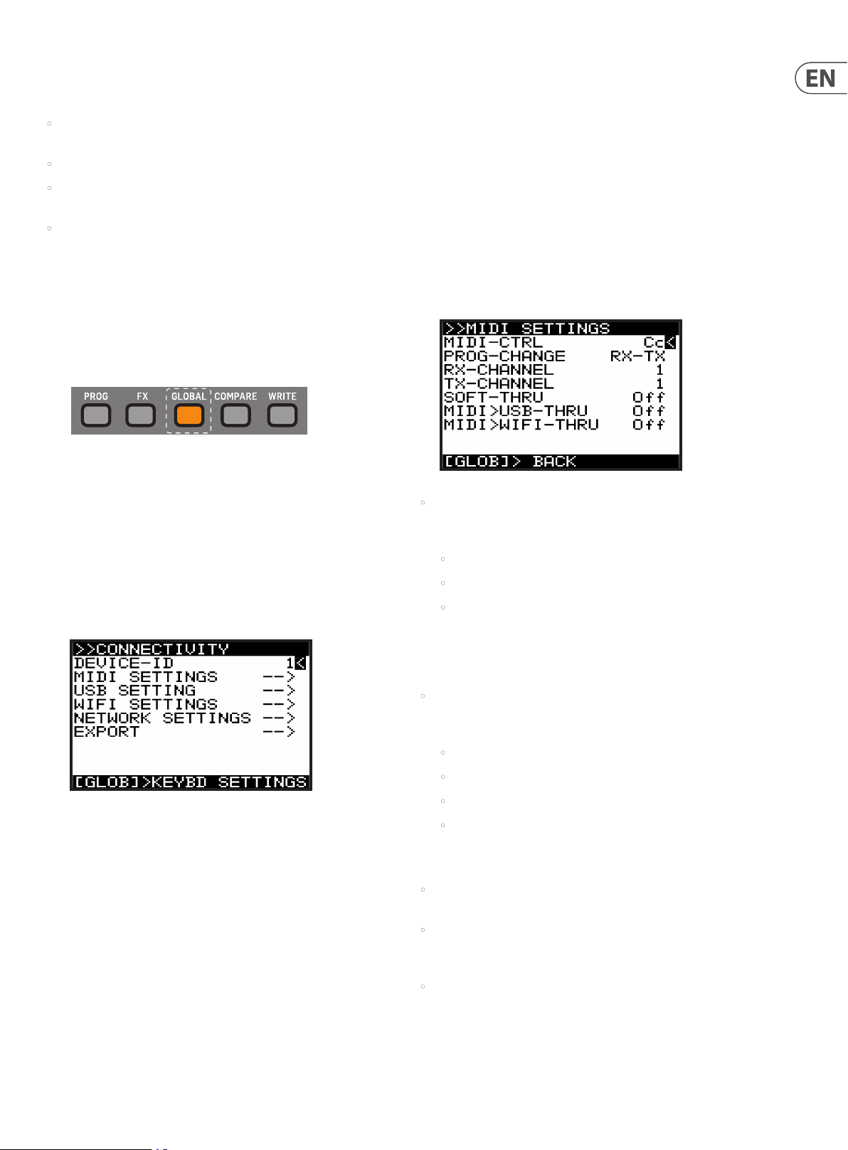
7.2 .10 MOVING EFFECTS
If you need to move an eect to a dierent slot, please follow this procedure:
1. Ensure you have saved any edits you have made to your current program
if required.
2. Press the FX switch to enter the FX OVERVIEW page.
3. Navigate to the eects slot you wish to move.
4. Press and hold the FX switch until you see the following message and the
BANK/UP, BANK/DOWN switches begin ashing:
5. While continuing to hold the FX switch, you can move the eects slot to
another location using one of these methods:
6. To move the slot to an adjacent upper slot press the BANK/UP switch.
7. To move the slot to an adjacent lower slot press the BANK/DOWN switch.
8. To move the slot to any other slot, turn the rotary knob.
9. You can continue to move the slot with any of the methods above, the new
slot will be highlighted as shown below:
10. Once you release the FX switch, the eect will be moved to the new slot.
Note: All eects parameters will be moved with the eec t.
Page 25
25 DeepMind 12D User Manual
7. 3 GLOBAL (Global Menu)
Within the GLOBAL menu there are four pages:
• CONNECTIVITY - All settings relating to connectivity and communication
with external devices including backup and restore functions.
• PEDAL SETTINGS - All settings relating to the pedal inputs.
• PANEL SETTINGS - All settings relating to panel (local), faders, dialogs,
menu functionality, and display brightness and contrast.
• SYSTEM SETTINGS - All system settings, including versions, fan speed,
calibration, and backup.
This chapter covers each of these pages in detail.
Note: To access successive GLOBAL pages, press the GLOBAL switch again to cycle
through the pages. A help message on the bottom of each screen shows you
what the next menu will be if you press the GLOBAL switch again.
1. To access the GLOBAL menu press the GLOBAL switch and it will remain
illuminated while you are in this menu:
2. The display will then show one page of the GLOBAL menu.
Note: The rst time you access the GLOBAL menu after turning on the
DeepMind 12D, you will see the CONNECTIVITY page. Whenever you access
the GLOBAL menu after that point, you will be returned to the last page
you visited within the menu system. This feature is reset when the unit is
powered o.
Note: This page location memory function can be turned o using the
REMEMBER PAGES function in the PANEL SETTINGS menu.
7.3.1 CONNECTIVITY
DEVICE ID - This is MIDI Device Identier (ID) which is used to identify the device.
This is important when multiple devices are present in a system, and ensures
that the device in question responds to the system exclusive messages which are
solely for the device in question.
The DEVICE ID can be any number from 1-16.
1. To change the DEVICE ID, make sure that the '<' symbol next to the DEVICE ID
number is highlighted. Then you can either use the -/NO or +/YES switches,
the rotary knob or the DATA ENTRY fader.
MIDI SETTINGS MENU - This menu contains settings for the MIDI sockets on the
rear of the DeepMind 12D.
1. To access the MIDI SETTINGS menu, make sure that the '<' symbol on the
MIDI SETTINGS line is highlighted. Then press the +/YES switch, you will now
see the MIDI SETTINGS menu.
• MIDI-CTRL - This option sets the MIDI CONTROLLER communication mode
for the DeepMind 12D MIDI sockets on the rear of the synthesizer. You can
choose from the following options:
• O (No controller messages will be sent)
• Cc (Continuous Controller)
• NRPN (Non-Registered Parameters).
Note: Both MIDI and NRPN data is always received and actioned.
In this menu are all the settings relating to connectivity and communication with
external devices, including backing up and restoring programs and data.
1. To navigate the options in the CONNECTIVITY menu, use the BANK/UP or
BANK/DOWN switches.
2. Selected parameters are adjusted using the -/NO or +/YES switches, the
rotary knob or the DATA ENTRY fader. The rotary knob has a click which
allows very accurate control. The fader allows rapid adjustment across the
full range.
Note: For more information on controlling the DeepMind 12D via MIDI,
please consult the section on MIDI later in this document.
• PROG-CHANGE - This option sets the PROGRAM CHANGE communication
mode for the DeepMind 12D MIDI sockets. You can choose from the
following options:
• RX - Program change messages will be received only.
• TX - Program changes will be transmitted only.
• RX-T X - Program changes will be transmitted and received.
• NONE - No program change messages will be sent or received.
Note: PROG-CHANGE is not available if POLY CHAIN is ON in the CHAIN
PARAMETERS page of the POLY EDIT menu.
• RX-CHANNEL - This option sets the MIDI channel that will be used to
RECEIVE MIDI messages. The CHANNEL can be ALL, or any number from 1-16.
• TX CHANNEL - This option sets the MIDI channel that will be used to
TRANSMIT MIDI messages. The CHANNEL can be any number from 1-16, or
RxCh, the same setting as the RX channel.
• SOFT-THRU - This option enables PASS-THRU mode from the MIDI INPUT
socket to the MIDI OUTPUT socket. (Any messages received at the MIDI INPUT
are passed thru to the MIDI OUTPUT socket.) The options are On or O.
Note: SOFT-THRU is not available if POLY CHAIN is ON in the CHAIN
PARAMETERS page of the POLY EDIT menu.
Page 26
26 DeepMind 12D User Manual
• MIDI>USB-THRU - This option enables PASS-THRU mode from the MIDI
INPUT socket to the USB host. The options are On or O.
• MIDI>WIFI-THRU - This option enables PASS-THRU mode from the MIDI
INPUT socket to the WIFI connection. The options are On or O.
2. To exit this menu press the GLOBAL switch to return to the
CONNECTIVITY menu.
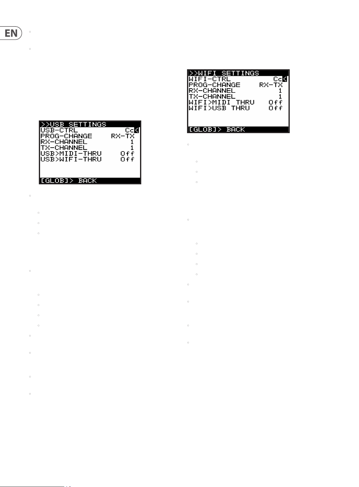
USB SETTINGS MENU- This menu contains settings for the USB por t on the rear
of the DeepMind 12D.
1. To access the USB SETTINGS menu, make sure that the '<' symbol on the USB
SETTINGS line is highlighted. Then press the +/YES switch, and the USB
SETTINGS menu will appear.
• USB-CTRL - This option sets the MIDI CONTROLLER communication mode for
the USB port on the rear of the synthesizer. You can choose
• O (No controller messages will be sent)
• Cc (Continuous Controller)
• NRPN (Non-Registered Parameters).
WIFI SETTINGS MENU- This menu contains settings for the WIFI connection of
the DeepMind 12D.
1. To access the WIFI SETTINGS menu, make sure that the '<' symbol on the
WIFI SETTINGS line is highlighted. Then press the +/YES switch, and the WIFI
SETTINGS menu will appear:
• WIFI-CTRL - This option sets the MIDI CONTROLLER communication mode for
the DeepMind 12D WIFI connection. You can choose:
• O (No controller messages will be sent)
• Cc (Continuous Controller)
• NRPN (Non-Registered Parameters).
Note: Both MIDI and NRPN data is always received and actioned.
Note: For more information on controlling the DeepMind 12D via WIFI-MIDI
please consult the section on MIDI later in this document.
• PROG-CHANGE - This option sets the PROGRAM CHANGE communication
mode for the DeepMind 12D WIFI connection. You can choose from the
following options:
Note: Both MIDI and NRPN data is always received and actioned.
Note: For more information on controlling the DeepMind 12D via USB-MIDI,
please consult the section on MIDI later in this document.
• PROG-CHANGE - This option sets the PROGRAM CHANGE communication
mode for the DeepMind 12D USB host port. You can choose from the
following options:
• RX - Program change messages will be received only.
• TX - Program changes will be transmitted only.
• RX-T X - Program changes will be transmitted and received.
• NONE - No program change messages will be sent or received.
• RX-CHANNEL - This option sets the MIDI channel that will be used to
RECEIVE MIDI messages. The CHANNEL can be ALL or any number from 1-16.
• TX CHANNEL - This option sets the MIDI channel that will be used to
TRANSMIT MIDI messages. The CHANNEL can be any number from 1-16, or
RxCh, the same setting as the RX channel.
• USB>MIDI-THRU - This option enables PASS-THRU mode from the USB port
to the MIDI-THRU socket. The options are On or O.
• USB>WIFI-THRU - This option enables PASS-THRU mode from the USB port
to the WIFI host. The options are On or O.
2. To exit this menu, press the GLOBAL switch to return to the
CONNECTIVITY menu.
• RX - Program change messages will be received only.
• TX - Program changes will be transmitted only.
• RX-T X - Program changes will be transmitted and received.
• NONE - No program change messages will be sent or received.
• RX-CHANNEL - This option sets the MIDI channel that will be used to
RECEIVE MIDI messages. The CHANNEL can be ALL or any number from 1-16.
• TX CHANNEL - This option sets the MIDI channel that will be used to
TRANSMIT MIDI messages. The CHANNEL can be any number from 1-16, or
RxCh, the same setting as the RX channel.
• WIFI>MIDI-THRU - This option enables PASS-THRU mode from the WIFI
connection to the MIDI-THRU socket. The options are On or O.
• WIFI>USB-THRU - This option enables PASS-THRU mode from the WIFI
connection to the USB host. The options are On or O.
2. To exit this menu, press the GLOBAL switch to return to the
CONNECTIVITY menu.
Page 27
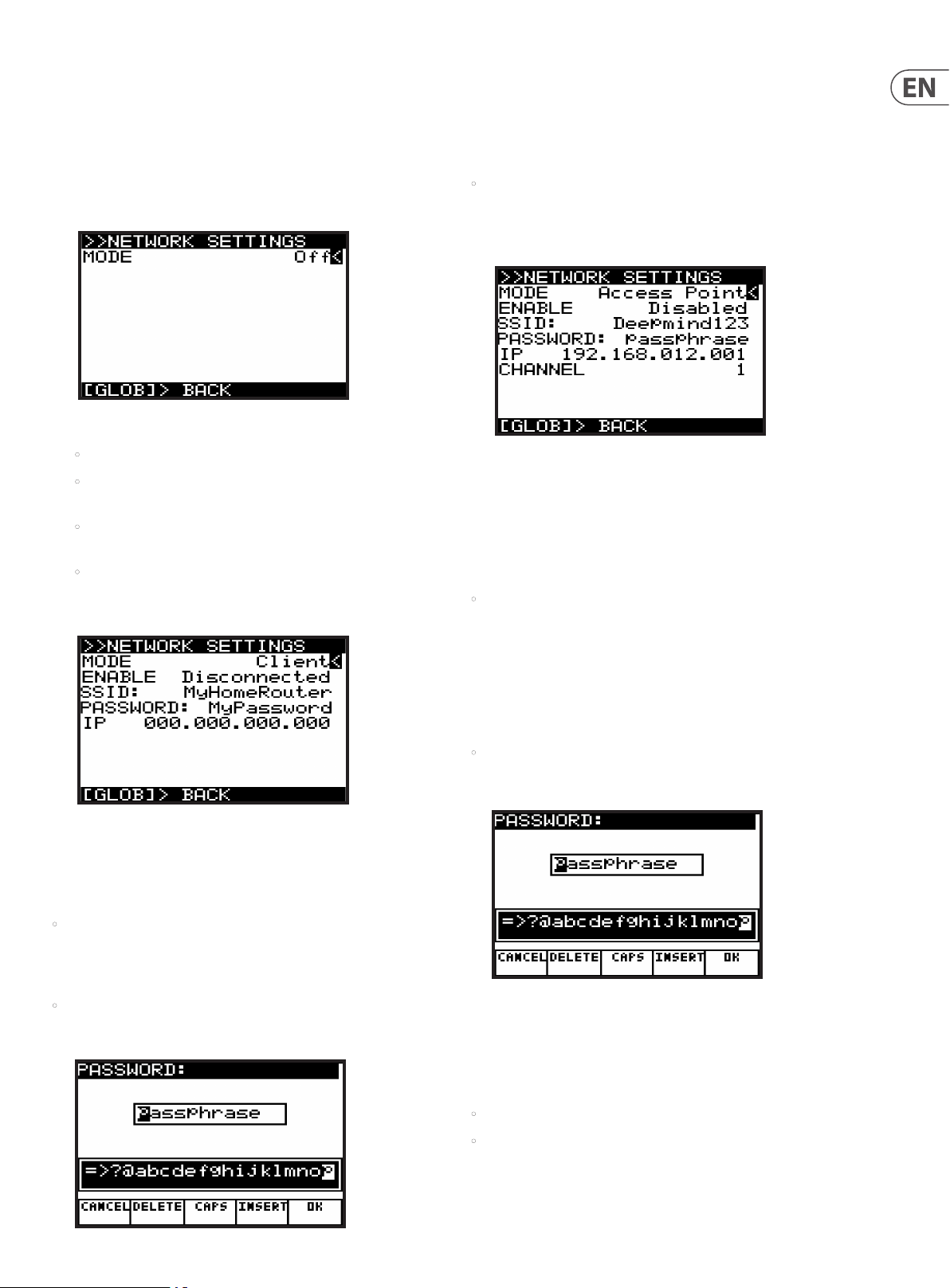
27 DeepMind 12D User Manual
NETWORK SETTINGS MENU- This menu contains settings for the network
connection of the DeepMind 12D.
The DeepMind 12D supports the Real-Time MIDI (RTP) protocol for use with
network devices/applications.
1. To access the NETWORK SETTINGS menu, make sure that the '<' symbol on
the NETWORK SETTINGS line is highlighted. Then press the +/YES switch,
and the NETWORK SETTINGS menu will appear:
2. There are three modes for the NETWORK connection:
• O - Network connection is disabled.
• Client - This mode allows the DeepMind 12D to act as a client so that it
can connect to an access point.
• Access Point (Soft ware Enabled Access Point) - The DeepMind 12D can
create an access point which will allow clients/devices to connect to it.
• The default mode for the NETWORK connection is O. The selected
mode persists across power cycles.
Client Mode - When Client mode is selected, additional options are displayed:
When editing any of the details, the dialog allows you to enter alphanumeric
characters and also shows CANCEL, DELETE, CAPS LOCK and INSERT options.
Once you have changed the details to your requirements, press the OK switch
to conrm the settings. Note: These details cannot be editied while ENABLE
is "Connected."
• IP - Shows the IP address assigned to the DeepMind12 by the DHCP server
running on the Access Point it is connected to.
Access Point Mode - When this mode is selected, additional options
are displayed:
In Access Point mode, you will need to enter the details of the access point you
wish to create.
1. To navigate the options in Access Point mode, use the BANK/UP and BANK/
DOWN switches.
2. In order to change any of the parameters make sure that the '<' symbol is on
the respective line, and press the +/YES switch to edit.
• ENABLE - This shows the current state of the Access Point connection.
There are 7 states: Disabled, Enabling, Enabled, Disabling, Connecting,
Connected, and Disconnecting. It is possible to enable the AP using
the +/YES switch, and disable the AP using the -/NO switch. Once the
AP is enabled, the connection status of any client that connec ts to
the DeepMind12 will be shown as either Connecting, Connected, or
Disconnecting. It is possible to reject a client that has already connected,
by pressing -/NO.
1. To navigate the options in Client mode, use the BANK/UP and
BANK/DOWN switches.
2. In order to change any of the parameters, make sure that the '<' symbol is on
the respective line, and press the +/YES switch to edit.
• ENABLE - This shows the current state of the Client Mode connection - there
are 4 states: Disconnec ted, Connecting, Connected, and Disconnecting.
Initiate a connection using the +/YES switch, and cancel a connection using
the -/NO switch. The connection is disconnected after each power cycle.
• SSID and Password - These are the SSID and Password strings that the
DeepMind12 uses to connect to the desired network. Editing the values of
these strings will bring up a text editing pop up dialog.
• SSID and Password - These are the SSID and Password strings the
DeepMind12 uses to create the Access Point network. Editing the values of
these strings will bring up a text editing pop up dialog.
When editing any of the details, the dialog allows you to enter alphanumeric
characters and also shows CANCEL, DELETE, CAPS LOCK and INSERT options.
Once you have changed the details to your requirements, press the OK switch
to conrm the settings. Note: These details cannot be editied while ENABLE
is "Connected."
• IP - Shows the IP address the DeepMind12 uses for the Access Point.
• Channel - This shows the Wireless channel used by the Access Point.
Page 28
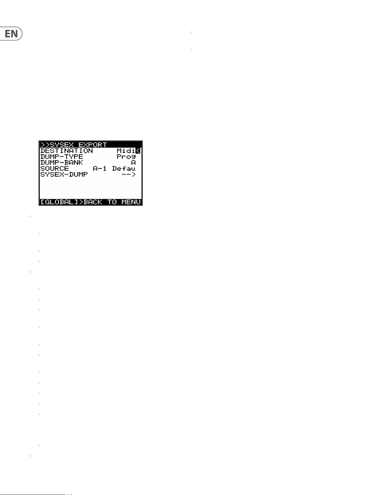
28 DeepMind 12D User Manual
SysEx EXPORT MENU- This menu contains settings for the SysEx EXPORT menu
of the DeepMind 12D.
Note: Backing up your data is an important factor when working with the
DeepMind 12D. It allows you to keep a safe copy of your programming, manage
settings depending on your use, and share your work with others.
In order to do this, you will need a MIDI utility for your computer which can
receive and transmit SysEx les. The utilites allow you to receive the SysEx les
from your DeepMind 12D, save them on your computer, and then allow exporting
of these les back to the DeepMind 12D. One example for the PC is called
"MIDI OX," and one for the Mac is "SysEx Librarian."
1. To access the SysEx EXPORT menu, press the GLOBAL switch until the
CONNECTIVITY menu appears. Make sure that the '<' symbol on the EXPORT
line is highlighted. Then press the +/YES switch, you will now see the
SysEx EXPORT menu.
• DESTINATION - This option sets the communication mode for the DeepMind
12D SYSTEM EXCLUSIVE (SysEx) messages.
• MIDI - SysEx messages will be transmitted from the MIDI sockets on the
rear of the synthesizer).
• USB - SysEx messages will be transmitted to the USB host.
• WiFi - SysEx messages will be transmitted to the WiFi connection.
• DUMP TYPE - This option sets the type of data which can be exported. You
can choose from the following:
• Prog - A single PROGRAM.
• Bank - An entire BANK of 128 PROGRAMs.
• EditProg -The PROGRAM in the EDIT BUFFER, i.e. the program you are
currently working on.
• Glob - The GLOBAL settings, useful if you need dierent settings
depending on your location, activity, or requirements.
• UserPat - Any one of the 32 USER PATTERNs from the Arpeggiator.
• EditPat -The current PATTERN stored in the EDIT BUFFER, i.e. the
PATTERN which is assigned in the program you are currently working on.
• AllPat - All user PATTERNs.
• All - All Banks, Programs, Patterns, and Global Settings.
• CalData - The data from the calibration routine.
• SOURCE - You can select the appropriate PROGRAM or PATTERN here. This
option is only available when exporting.
• SysEx DUMP (EXPORTING) - Pressing the +/YES switch while this option
is selected, will initiate the EXPORT, based on the selected options. Before
exporting, you need to run your MIDI utility on your computer, and set it
up to receive (import) a MIDI SysEx le. When the le is exported to the
computer, it can be saved for later recall.
2. To exit the SysEx EXPORT menu, press the GLOBAL switch to return to the
CONNECTIVITY menu. To exit the CONNECTIVITY menu, press the PROG switch
to return to the main programming screen, or press GLOBAL to cycle to the
PEDAL SETTINGS menu.
SysEx Export Example
The following details show an example of using the SysEx EXPORT menu to
export a le to a computer.
Note: the information below shows the general idea of the SysEx export
procedure using two popular MIDI utilities, but the exact details depend on the
software, and that may dier or change without notice. Company names and
software names may be trademarks or registered trademarks of their respective
owners, and are hereby acknowledged.
Using SysEx Librarian (OSX):
1. Connec t the DeepMind 12D to your Mac using a USB cable or MIDI interface.
2. Open SysEx Librarian on the computer and select the DeepMind 12D as the
target from the drop down menu at the top of the window. (Or select the
appropriate MIDI interface from the menu if you are using one).
3. On the DeepMind 12D, in the SysEx EXPORT menu, select the DESTINATION,
such as MIDI or USB.
4. On the DeepMind 12D, in the DUMP-TYPE menu, select the item that is to
be exported.
5. Navigate to SysEx-DUMP but DO NOT press the +/YES switch just yet.
6. Using SysEx Librarian, click on the Record One button, this will arm the
program to record any SysEx information.
7. On the DeepMind 12D, press the +/YES button and the le will be sent.
8. SysEx Librarian should capture the information. Select the newly created le
and select File->Save As SysEx to save the Edit buer dump.
Using MIDI OX (Windows PC):
1. Connec t the DeepMind 12D to your PC using a USB cable or a MIDI interface.
2. Open MIDI OX and select MIDI devices from the Options drop down menu.
3. Select the DeepMind 12D as the Input and Output device. (Or select the
appropriate MIDI interface from the menu if you are using one).
4. On the DeepMind 12D, in the SysEx EXPORT menu, select the DESTINATION,
such as MIDI or USB.
5. On the DeepMind 12D, in the DUMP-TYPE menu, select the item that is to
be exported.
• Chord - The data from setting up a CHORD.
• P-Chord A - The various POLY CHORDs you have set up and stored in
the current POLY CHORD Bank. In this example, it is Bank A. If you want
to save another POLY CHORD Bank, press and hold the POLY EDIT switch
and change banks with the soft switches.
• Favorites - The list of favorite programs you have created and stored.
• DUMP BANK - You can select the appropriate BANK here, from one of the 8
available program banks (A-H). This option is only available when exporting.
6. Navigate to SysEx-DUMP but DO NOT press the +/YES switch just yet.
7. Using MIDI OX, select View SysEx… from the View drop down menu.
8. In the newly opened window, select SysEx->Receive Manual Dump…
9. On the DeepMind 12D, press the ‘+/YES’ switch to send the le.
10. MIDI OX should capture and display the information. Select Save As… from
the Display Window drop down menu and save the SysEx dump with a
suitable name.
Page 29
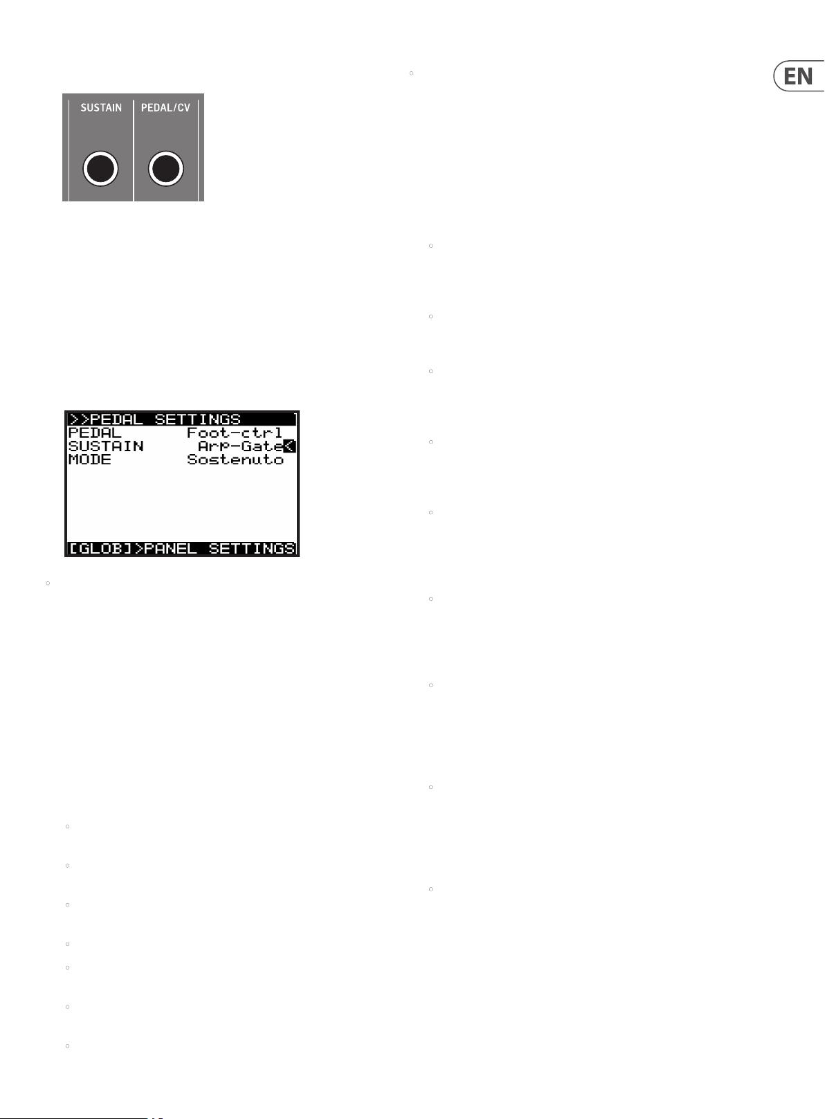
29 DeepMind 12D User Manual
7.3. 2 PEDAL SETTINGS
In this menu are all the settings relating to PEDAL/CV and SUSTAIN inputs on the
rear of the DeepMind 12D.
1. To navigate the options in the PEDAL SETTINGS menu, use the BANK/UP and
BANK/DOWN switches.
2. In order to change any of the parameters make sure that the '<' symbol on
the respective line is highlighted.
3. Selected parameters are adjusted using the -/NO or +/YES switches, the
rotary knob or the DATA ENTRY fader. The rotary knob has a click which
allows very accurate control. The fader allows rapid adjustment across the
full range.
• SUSTAIN - This option allows you to choose the SUSTAIN MODE from the
following options:
The SUSTAIN input can work with a switched input which is either open
when pressed, or closed when pressed.
Gate Functionality - The SUSTAIN input can also be used with a GATE
signal from a CV and GATE interface or a modular synthesizer. This
functionality requires the GATE signal to operate between +5V and 0V.
Note: For wiring diagrams and pin connections information please consult
the guide later in this document.
• Norm-Open - Here, when the connected switch is pressed, the notes
are held in the SUSTAIN stage of all ENVELOPEs. In this mode the correct
operation is designed for a switch whose contacts close when pressed.
This is the default setting.
• Norm-Closed - Here, when the connected switch is pressed, the notes
are held in the SUSTAIN stage of all ENVELOPEs. In this mode the correct
operation is designed for a switch whose contacts open when pressed.
• Tap-N.O - Here the SUSTAIN input is mapped to the TAP function, so
when the switch is pressed a signal is sent to the Master BPM Generator.
In this mode the correc t operation is designed for a switch whose
contacts close when pressed.
• Tap-N.C - Here the SUSTAIN input is mapped to the TAP function, so
when the switch is pressed a signal is sent to the Master BPM Generator.
In this mode the correc t operation is designed for a switch whose
contacts open when pressed.
• PEDAL - This option allows you to choose the PEDAL/CV MODE from the
following options:
The PEDAL/CV input can work with a typical foot pedal, where the voltage
is supplied by the DeepMind 12D and fed back at a level which is dependant
on the position of the pedal. The further the pedal is pressed, the higher
the voltage.
The PEDAL/CV input can also work with a CV (Control Voltage) input from any
source with a 0 to +5 Volt output, for example, the control voltage from a
modular synthesizer.
Note: For wiring diagrams and pin connections information please consult
the guide later in this document.
The PEDAL input takes the voltage from the connector and turns it into a
control signal. The control signal can be mapped to any of the following:
• Foot-ctrl - The Foot-Ctrl (Foot Controller) is available as a modulation
source in the MOD MATRIX. This is the default setting.
• Mod-Wheel - Here the PEDAL input is mapped to the MODULATION
WHEEL which is available as a modulation source in the MOD MATRIX.
• Breath - Here the PEDAL input is mapped to the BREATH controller
which is available as a modulation source in the MOD MATRIX.
• Volume - Here the PEDAL input is mapped to the VOLUME controller.
• Expression - Here the PEDAL input is mapped to the
EXPRESSION controller.
• Porta Time - Here the PEDAL input is mapped to the
PORTAMENTO TIME.
• Aftertouch - Here the PEDAL input is mapped to the
AFTERTOUCH control.
• Arp+Gate - Here the SUSTAIN input is mapped to the ARPEGGIATOR
notes, so when a GATE input from a CV & GATE interface, or a modular
synthesizer is connec ted, the gate signal will step though the notes of
the ARPEGGIATOR. In this mode the ARPEGGIATOR note duration is set by
length of time that the gate signal is high (+5V).
• Arp-Gate - Here the SUSTAIN input is mapped to the ARPEGGIATOR
notes, so when a GATE input from a CV & GATE interface, or a modular
synthesizer is connec ted, the gate signal will step though the notes of
the ARPEGGIATOR. In this mode the ARPEGGIATOR note duration is set by
length of time that the gate signal is low (0V).
• Seq+Gate - Here the SUSTAIN input is mapped to the CONTROL
SEQUENCER steps, so when a GATE input from a CV & GATE interface, or
a modular synthesizer is connected, the gate signal will move though
the steps of the CONTROL SEQUENCER. In this mode the CONTROL
SEQUENCER will transition to the next step each time a positive edge (a
transition from 0V to 5V) is received.
• Seq-Gate - Here the SUSTAIN input is mapped to the CONTROL
SEQUENCER steps, so when a GATE input from a CV & GATE interface, or
a modular synthesizer is connected, the gate signal will move though
the steps of the CONTROL SEQUENCER. In this mode the CONTROL
SEQUENCER will transition to the next step each time a negative edge (a
transition from 5V to 0V) is received.
• Arp&Seq+Gate - Here the SUSTAIN input is mapped to the
ARPEGGIATOR notes, and to the CONTROL SEQUENCER steps. When
a GATE input from a CV & GATE interface, or a modular synthesizer
is connected, the gate signal will step though the notes of the
ARPEGGIATOR, and also move though the steps of the CONTROL
SEQUENCER. In this mode the ARPEGGIATOR note duration is set by
length of time that the gate signal is high (+5V). Also in this mode
the CONTROL SEQUENCER will transition to the nex t step each time a
positive edge (a transition from 0V to 5V) is received.
continued
Page 30
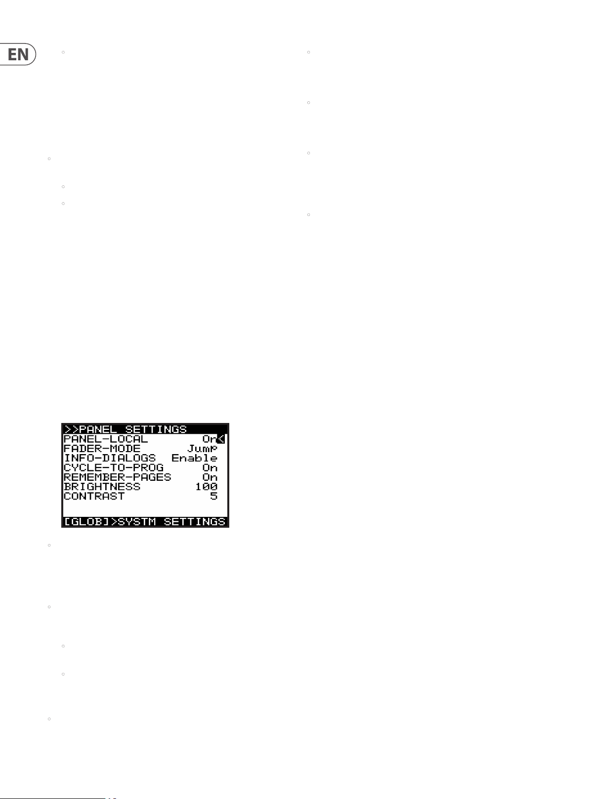
30 DeepMind 12D User Manual
• Arp&Seq-Gate - Here the SUSTAIN input is mapped to the
ARPEGGIATOR notes, and to the CONTROL SEQUENCER steps. When GATE
input from a CV & GATE interface, or a modular synthesizer is connec ted,
the gate signal will step though the notes of the ARPEGGIATOR, and also
move though the steps of the CONTROL SEQUENCER. In this mode the
ARPEGGIATOR note duration is set by length of time that the gate signal
is low (0V). Also in this mode the CONTROL SEQUENCER will transition
to the next step each time a negative edge (a transition from 5V to 0V)
is received.
• MODE - There are 2 overall pedal modes: Sustain and Sostenuto, as
explained below:
• Sustain – sustain is held for all notes while the pedal is down.
• Sostenuto – sustain is held for those notes played while the sustain
pedal is down. This is the "middle pedal" action of the 3 pedals of a
traditional piano.
4. To exit the PEDAL SETTINGS menu, press the PROG switch to return to
the main programming screen, or press GLOBAL to cycle to the PANEL
SETTINGS menu.
7.3.3 PANEL SETTING
In this menu are all the settings relating to the DeepMind 12D Panel Controls.
1. To navigate the options in the PANEL SETTINGS menu, use the BANK/UP and
BANK/DOWN switches.
• CYCLE TO PROG - When this option is turned On, the menu cycle function
will return you to the programming screen. When this option is O, the
menu cycle function will return you to the rst menu page. The default
setting is On.
• REMEMBER PAGES - With this option turned on your position in any menu
will be remembered so that you return to the same position you left. When
this option is o, any access of a menu will always position you in the rst
menu page. The default setting is On.
• BRIGHTNESS - This option allows you to control the brightness of the
display. The range is 0-100, with 0 being dim and 100 being the brightest
setting. This is useful if you are operating in low light conditions and want
to protect your vision, or if you are working under strong lighting conditions
and want to maximise viability. The default setting is 100.
• CONTRAST - This option allows you to control the contrast of the display. The
range is 0-14, with 0 being least contrast and 14 being the most contrast.
This is useful to compensate for dierent viewing angles, and/or light
conditions. The default setting is 10.
4. To exit the PANEL SETTINGS menu, press the PROG switch to return to
the main programming screen, or press GLOBAL to cycle to the SYSTEM
SETTINGS menu.
2. In order to change any of the parameters make sure that the '<' symbol on
the respective line is highlighted.
3. Selected parameters are adjusted using the -/NO or +/YES switches, the
rotary knob or the DATA ENTRY fader. The rotary knob has a click which
allows very accurate control. The fader allows rapid adjustment across the
full range.
• PANEL-LOCAL - This option turns LOCAL CONTROL for the DeepMind 12D
panel controls (including all faders, non menu edit switches and portamento
knobs) On and O. It is sometimes useful to turn LOCAL CONTROL o when
using the DeepMind 12D to control other hardware/software synthesizers,
eects and/or applications. The default setting is On.
• FADER MODE - This option allows you to choose the mode in which the
faders respond when you initially move a fader which has a dierent physical
position to the stored value. You can choose one of the following options:
• Pass-thru - In this mode, when the fader is moved, it will need to
"Pass-thru" the stored value before it will start to change.
• Jump - In this mode, when the fader is moved, the value of the
parameter will "Jump" to the physical position of the fader.
The default setting is Jump.
• INFO DIALOGS - This option allows you to disable the pop-up dialogs and
messages which are designed to aid you while learning how the DeepMind
12D operates. The default setting is Enable.
Page 31

31 DeepMind 12D User Manual
7.3. 4 SYSTEM SETTINGS
In this menu are all the SYSTEM SETTINGS of the DeepMind 12D. These include
VERSION NUMBERS of the hardware/rmware, settings for the fan speed, and
access to the CALIBRATION routines.
1. To navigate the options in the SYSTEM SETTINGS menu, use the BANK/UP and
BANK/DOWN switches.
2. In order to change any of the parameters make sure that the '<' symbol on
the respective line is highlighted.
3. Selected parameters are adjusted using the -/NO or +/YES switches, the
rotary knob or the DATA ENTRY fader. The rotary knob has a click which
allows very accurate control. The fader allows rapid adjustment across the
full range.
• HOST-VER - This is the version number of the host rmware.
• VOICE-VER - This is the version number of the voice circuit board rmware.
• DSP-VER - This is the version of the DSP rmware.
• BOOT-VER - This is the version of the bootloader used to initialize
the synthesizer.
• WIFI-VER - This is the version of the WiFi.
• FAN-SPEED - This allows you to adjust the fan speed. The fan speed is
adjustable from 0 (o) to 255 (maximum). Adjust the fan speed to suit your
listening conditions and preference. If the local temperature is high, please
make sure that the fans are not turned o. The DeepMind 12D is equipped
with 2 fans, one internal and one at the rear. At an approximate setting of 40
the internal fan is running and the rear fan is o.
CALIBRATE (Calibration Menu)
This menu in the SYSTEM SETTINGS menu allows you to perform CALIBRATION of
the VOICES and PEDAL INPUT.
1. To navigate the options in the CALIBRATION menu, use the BANK/UP or
BANK/DOWN switches.
2. Selected parameters are adjusted using the -/NO or +/YES switches, the
rotary knob or the DATA ENTRY fader. The rotary knob has a click which
allows very accurate control. The fader allows rapid adjustment across the
full range.
3. In order to star t a calibration routine, make sure that the '<' symbol on the
appropriate CALIBRATE line is highlighted, and then press the +/YES switch.
The DeepMind 12D has 12 voices. Each voice has its own LFO, OSC, VCF, ENV and
VCA stages.
The CALIBRATION routine is used for Voice checking, OSC wave shapes, VCF
self-oscillation, Pulse Width modulation and the VCA bias.
VCF - Unlike many other synthesizers, the DeepMind 12D is capable of
accurate pitch tracking even when the lter resonance is pushed to (and
past) the point where the lter starts to self-oscillate. When using this selfoscillating feature of the VCF as a sound source, the VCF calibration ensures
the correct response when playing the entire scale of the keyboard.
The DeepMind 12D VCFs are calibrated at the factory during produc tion.
However, because its lters are voltage controlled and can be aec ted
by extremes of temperature, you may need to use the built-in calibration
function to ne tune them occasionally. Calibration may also be required
after a rmware upgrade or when requested to do so by an authorized
Behringer support technician.
OSC - The DeepMind 12D OSCs are calibrated at the factory during
production. The oscillators are discrete analog circuits, but they are digitally
controlled. Compared to a Voltage Controlled oscillator (VCO), the OSC has far
superior stability, especially when they have very high frequency, low-jitter
master clock sources, as used in the DeepMind 12D. This stage calibrates the
slope of the sawtooth waveform to ensure even volume and pulse-width
across the full range of the synthesizer.
This means that the OSCs should never need re-calibrating except after a
rmware upgrade, or when requested to do so by an authorized Behringer
support technician.
Page 32

32 DeepMind 12D User Manual
CALIBRATE VOICES
Overview of the calibration routines:
• ALL - This will initiate all of the routines.
• VOICE CHECK - This performs a series of functionality tests on each voice.
• VCF - This routine puts the voice into self oscillation and tunes to 1 kHz in
order to calibrate the resonance of the VCF for that voice. The routine then
puts the voice into self oscillation and checks the tuning at 50 Hz, 220 Hz,
880 Hz and 10 kHz to ensure the VCF is performing as expected. The test is
repeated for all voices.
• VCF FINE - This routine tests the scale and oset for all voices.
• OSC - This routine adjusts the slope of the sawtooth at octave intervals. This
ensures the precision of the slope so that it performs as designed. The test is
repeated for all voices.
• PW - This routine adjusts the pulse width (mark to space ratio) of the
pulsewave. This ensures the precision of the ratio so that it performs
as designed. The test is repeated for all voices.
CALIBRATE PEDAL
To calibrate the PEDAL please use the following process:
Note: During the calibration the GLOBAL, -/NO and +/YES switches will
be ashing. If at any time you want to cancel the calibration routine, you can
press the -/NO switch. No previous calibration data will be changed if you do
cancel the routine. To conrm the calibration at each stage press +/YES as
described below.
1. In order to start the calibration routine, make sure that the '<' symbol on the
CALIBRATE PEDAL line is highlighted and press +/YES.
2. You will see the following display showing a bar representing the current
PEDAL value (0% for no pressure). Also on this screen you can see the stored
calibration data above the bar and the current value below the bar:
3. Then press the pedal until the value stops increasing.
4. You will see the following display showing the maximum position of the
PEDAL input and the associated value:
• VCA - The Voltage Controlled Amplier (VCA) uses a bias voltage to set
its operating level. This bias voltage is balanced so that the VCA responds
as designed. The test is repeated for all voices.
To start the calibration routine, please follow the procedure below:
1. In order to start the calibration routine, make sure that the '<' symbol is on
the appropriate CALIBRATE line and highlighted, and press the +/YES switch.
Note: The calibration run time is shown on the bottom of the screen so that
you can plan your work around any of the calibration phases.
2. The calibration routine will then start. Throughout the tests you will see
various waveforms being played. It is safe to turn down the volume while
the calibration routine is running.
Note: While the calibration is running, you can mute the signal using the
BANK/DOWN switch and un-mute using the BANK/UP switch.
3. When the calibration routine is complete, you will see a summar y of the test
results as shown below. The 1st column is Voice 1, 2nd is Voice 2, and so on:
Note: To cancel the routine, press the -/NO switch, and you will see the
following message:
5. To conrm the CALIBRATION of the PEDAL input, press the +/YES switch: The
calibration data will then be stored for the PEDAL and you will be returned
to the CALIBRATE menu. From here you can perform another calibration
from the menu, or press the GLOBAL switch again to return to the SYSTEM
SETTINGS menu.
Note: During the calibration, the GLOBAL and -/NO switches will be ashing.
If at any time you want to cancel the calibration routine, you can press the
-/NO switch. No previous calibration data will be changed if you cancel
the routine.
Page 33

33 DeepMind 12D User Manual
BACKUP (Backup Menu)
The last item in the SYSTEM SETTINGS menu is BACKUP.
1. Pressing +/YES when “BACKUP -->” is selected, will bring up the BACKUP
MENU. (The "RESTORE BANK" lines only appear af ter the rst backup
is done).
2. Pressing +/YES when “BACKUP PROGRAMS” is selected, will bring up a
conrmation dialog:
3. Pressing +/YES again, will copy all Banks of programs from EEPROM to
ash, and overwrites the “factory default” data.
4. Pressing +/YES when any of the RESTORE-BANK-A to RESTORE-BANK-H lines
is selected, will bring up a conrmation dialog:
5. Pressing +/YES again will restore the selec ted bank from ash.
6. Press GLOBAL to return to the SYSTEM SETTINGS menu, and press again to
return to the PROG menu.
Page 34

34 DeepMind 12D User Manual
7.4 COMPARE (Compare Menu)
The COMPARE feature has two main functions:
• Firstly you can use it to COMPARE the current (edited) program with the
original program.
• Secondly you can use it to COMPARE and/or match the current position of the
physical faders on the surface with the original program. This is necessary
when you wish to maintain the sound/character of the program.
1. To perform both functions, press the COMPARE switch.
2. You will then see a page of the COMPARE menu. The page shown will be the
last page you used. If you have not used the COMPARE function since turning
the DeepMind 12D on, it will default to page 1 (shown below).
• If you have edited the program (i.e. changed some parameters), when
you press the COMPARE switch, you will restore the original stored
program so you can compare your edits to the original sound. Press
COMPARE again if you want to return to the edited version. Repeat this
to quickly compare the original and edited versions.
• In the COMPARE menu, you have the option to match the current
position of the faders to the positions stored in the original program. If
you do not want to match the fader positions, press COMPARE again to
return to your edited program.
5. There are four pages of faders in the COMPARE menu, use the -/NO or +/YES
switches to selec t the previous or next pages, or just move a fader and its
COMPARE page will appear automatically.
Page 1 shows the ARP/SEQ and LFO faders. (The Portamento rotary knob is
represented by the rst fader on the left.)
Page 2 shows the OSC faders:
3. Each page of the COMPARE menu shows a section of the faders.
• If the position of the fader matches the position of the stored value,
the fader will be black.
• If the fader does not match the position it will be white with a
superimposed arrow pointing in the direction it needs to move in order
to approach the stored value.
• There is also a narrow white bar to show how far the fader needs to
move in order to match the stored value.
4. If you adjust a fader until it reaches the stored position, it will turn black to
indicate it is now matched.
Page 3 shows the UNISON, VCF, HPF and VCA faders:
Page 4 shows the ENVELOPE faders:
Note: You can still select specic envelopes to match the faders, depending
on your requirements.
6. Press COMPARE again to exit the COMPARE menus at any time and return to
the PROG menu.
Page 35

35 DeepMind 12D User Manual
7. 5 WRITE (Write Menu)
1. To write a program to memory, rst press the WRITE switch.
2. The WRITE PROGRAM menu will then appear:
3. In this menu you can use the -/NO or +/YES switches to navigate through the
sections. The selected section will be highlighted by an inverted character
(white on black).
4. The rst section is the program location where the current program will be
saved. You can use the BANK/UP, BANK/DOWN switches, the rotary knob,
or the DATA ENTRY fader to select the required BANK (A-H) and PROGRAM
NUMBER (1-128). Be careful that you do not overwrite an existing program
you would rather keep.
5. The second section is the "CATEGORY" where you can select any of the
available program categories. Again you can use the BANK/UP, BANK/DOWN
switches, the rotary knob, or the fader to select the required category.
6. The third section is "TO BE REPLACED BY" which shows the name of the
program to be written. If you want to change the name, you can use the -/NO
or +/YES switches to step through each character of the name and use the
BANK/UP, BANK/DOWN switches, the rotary knob, or the faders to change
the character.
8. To compare the current program with the intended program location, you
can press the COMPARE switch to listen to the dierence. To return to the
current program, press the COMPARE switch again.
9. Once you have selected the new location and named the program, press the
WRITE switch again to write the program.
At any time you decide not to write the program, press the PROG switch to
return to the main programming display.
Note: If there is a program in the backup memory (such as an unsaved
edited program), then you will see the message "COMPARE: Clear Backup".
10. If you wish to listen to the intended program location as described earlier,
you will need to press the COMPARE switch to rst clear the backup
memory. Once the backup has been cleared then the message will revert
to "COMPARE: Listen" and you can listen to the intended program location
as normal.
7.6 Renaming Programs
1. To rename an existing program, follow the procedure above for writing a
program, keep the BANK and PROGRAM NUMBER the same, and then change
the name shown in the "TO BE REPLACED BY" section.
7. There are also two short-cuts for selecting characters, indicated by text in
bottom of the display, just above the FX and GLOBAL switches.
Note: These two short-cuts will only appear when you are editing the name
of the TO BE REPLACED BY program.
a-A-0 - Press the FX switch to cycle between lower-case, upper-case, and
numbers/special characters.
DEL - Press the GLOBAL switch to delete the currently selected character.
Page 36

36 DeepMind 12D User Manual
8. Programming
8.1 CHORDS/ARP/SEQ/SYNC SETTINGS
The ARP/SEQ section controls all parameters relating to the internal
ARPEGGIATOR, CONTROL SEQUENCER, and PATTERN editing. This section also
contains the controls for CHORD and POLY CHORD programming.
• CHORD / POLY CHORDS - You can program a single chord to be mapped
across the entire keyboard, or multiple poly chords to individual keys/notes.
• ARPEGGIATOR - The ARPEGGIATOR allows you to play a pattern based on
the individual keys being held. The pattern's note order can be selected
from a number of modes. The tempo of the ARPEGGIATOR can be sourced
from either an internal or external clock. The clock can be divided from the
Master BPM, allowing you to select dierent timing struc tures.
The ARPEGGIATOR also has a looping pattern editor which allows you to
adjust the velocity and gate values for each step. The pattern editor has
32 "Fixed Presets" allowing you to start using the patterns quickly, and 32
"User Presets" so that you can create and store your own unique patterns.
The patterns can be up to 32 steps long, allowing for a large range of
creative possibilities.
8.1.1 CHORD SWITCH
The CHORD switch in the top left allows you to program a chord into memory.
That chord is then transposed across the full range of the keyboard.
If a chord has already been programmed, then pressing the CHORD switch allows
you to play in CHORD mode.
ILLUMINATED
When the CHORD switch is pressed, it will illuminate, and the chord screen will
appear in the display. (If no chord is currently stored, then the switch will ash.)
CHORD SCREEN UPPER SECTION - At the top of the chord screen is a visual
representation of the entire MIDI note range (0-127). Changing the Octave shift
setting on your keyboard (if available) will update the available keys. If no chord
has been created, the upper section of the screen will look like this:
There is also a clock swing feature which allows you to ne tune the swing
(or "groove") to your specic requirements.
The ARPEGGIATOR can be set to synchronize with the rst key you strike,
or synchronised with the Master BPM clock (internal or ex ternal).
• CONTROL SEQUENCER - This is not part of the ARPEGGIATOR, it is a
modulation source in the same way as an LFO or ENVELOPE is. The CONTROL
SEQUENCER allows you to create a pattern which can be used to modulate
other parameters. The tempo of the CONTROL SEQUENCER can be sourced
from either an internal or external clock. The clock can be divided from the
Master BPM allowing you to select dierent timing struc tures.
The CONTROL SEQUENCER has a looping editor which allows you to adjust the
values for each step. The modulation waveform that is produced can have
negative or positive values. The CONTROL SEQUENCER can be up to 32 steps
long allowing for a large range of creative possibilities.
There is also a clock swing feature which allows you to ne tune the swing
(or "groove") to your specic requirements.
The CONTROL SEQUENCER can be set to synchronize with the rst note you
strike, or synchronised with the Master BPM clock (internal or external).
For more information on using the CONTROL SEQUENCER as a modulation
source, please consult the MOD MATRIX section later in this document.
• CLOCK NOTES - One of the great advantages of having a Master BPM is that
the LFOs, ENVELOPES, and many EFFECTS parameters of the DeepMind 12D
can be synchronised to the BPM.
If a chord has been created, there will be small "pegs" above and below the
keyboard that show the notes in the chord, and an arrow above and below that
shows the position of the last-pressed note that triggered the chord:
CHORD SCREEN LOWER SECTION - The lower section of the chord screen
shows a zoomed-in sec tion of the keyboard, an octave either side of the
last-pressed note.
Page 37

37 DeepMind 12D User Manual
• The letter T on the highlighted key shows the last played note.
• The letter E appears on the key as well, as this is a MIDI trigger from your
external keyboard.
• The small dots on the keys show the current component notes of the chord.
CHORD SCREEN SOFT KEYS - At the bottom of the chord screen are 3 labels
which indicate the sof tware function of the illuminated PROG, GLOBAL and WRITE
switches. If no previous chord is present, the display will show the status of the
chord programming function, for example: ARMED, LEARNING, or PRESS TRIGGER,
as explained later.
• PROG switch - Performs the EXIT function and returns to the PROG screen.
• GLOBAL switch - Used to RECORD a new chord over an existing chord.
• WRITE switch - Used to DELETE the chord, but only once a chord is
programmed (otherwise this area will be blank and the WRITE switch will
not be illuminated)
4. The status line shows the text "CUSTOM-TYPE-NOTES" where:
• CUSTOM - indicates this is a chord you have created.
• TYPE - If the chord type is recognized as one that is saved in the WIZARD
memory (described in the Poly Chord section later), then the chord TYPE
is displayed. For example, the chord shown above is TYPE = Ma.
• NOTES - The component notes of the chord.
5. You will now be asked to assign the chord to a trigger key: “PRESS TRIGGER”
will appear in the display as shown:
FLASHING SLOW
6. Press any key on your keyboard, and the screen will change to show the
details of your new custom chord in the status line. The example below is a
Major chord (Ma) with the trigger F3, and notes F3, A3, and C4.
Note: The chord is stored in persistent memory and will be retained through a
power cycle. Only one chord is created and stored at a time.
Note: The chord memory can also be cleared using the "bootloader" menu
described later in this document.
Note: The chord size is limited to 12 notes.
CHORD PROGRAMMING
1. To program a chord, rst press the CHORD switch. If there is no previous
chord in memory, the CHORD switch will begin double ashing and the
message "ARMED" will appear in the display as shown:
2X FLASHING FAST
2. Play the desired chord, and "LEARNING" will appear in the display as shown:
ILLUMINATED
• PLAYING THE CHORD - While the CHORD switch is still illuminated, press
any key on the keyboard to play the chord you just programmed. The chord
will be transposed from the root note to every key that you play.
• RECORDING A NEW CHORD - While you are still in the chord mode (the
CHORD switch is still illuminated), you can record a new chord and overwrite
the existing chord, by pressing the REC soft switch. The existing chord will
be deleted and "ARMED" will appear again, allowing you to program a new
chord as before.
• DELETING THE CHORD - To delete the chord, press the DEL soft switch.
The chord will be deleted and "ARMED" will appear again, allowing you to
program a new chord as before.
3. You can add additional notes to the chord as long as at least one note is still
being held down. Release all the keys when you are done.
2X FLASHING FAST
• EXITING THE CHORD SCREEN - Press the EXIT soft switch to exit the
chord screen at any time. This will return you to the PROG screen, but the
chord mode will still be active for playback, and the CHORD switch will still
be illuminated.
Page 38

38 DeepMind 12D User Manual
• EXITING CHORD MODE - After you have pressed EXIT, and the screen has
returned to the normal PROG view, press the CHORD switch again to turn o
chord mode. The CHORD switch will no longer be illuminated.
Note: Only the trigger notes from the external keyboard will be sent to any
connected devices. When trigger notes are received, the DeepMind 12D will
play respective chords based on incoming trigger notes.
8.1.2 POLY CHORD
The POLY CHORD switch allows you to program multiple chords into memory, and
assign them to individual xed trigger keys. Pressing the trigger keys will then
play the chords you have created, and you are able to play other keys and chords
at the same time. Note: Only 12 voices can play at the same time, unless you
have multiple synthesizers running in poly chain mode.
ILLUMINATED
POLY CHORD BANKS - There are 4 memory banks (A, B, C, and D) in which to
store and recall your poly chords. The banks are only used in poly chord mode,
not chord mode. The letter at the top right of the POLY CHORD display screen
always shows the current bank.
Note: Only one bank is in use at a time during playback, exporting or importing.
Shortcut: To quickly change banks at any time:
1. Press and hold the POLY CHORD switch, and the following screen
will appear.
2. While still holding down the POLY CHORD switch, press the soft switch below
the Bank you want to reach. The bank letter will change in the top right of
the display. The -/NO and +/YES switches and the rotary knob can also be
used to change banks at this time.
3. When you reach the desired bank, release the POLY CHORD switch.
POLY CHORD DISPLAY (UPPER SECTION) - Press the POLY CHORD switch to
bring up the poly chord screen. At the top is a visual representation of the entire
MIDI note range (0-127). The brackets show the 2-octave zoom position for the
lower section. Changing the Octave Shift setting of your keyboard (where
available) will update the available keys.
Page 39

39 DeepMind 12D User Manual
PEG MODES - Above and below the keyboard illustration are small "pegs" that
show the keys that are notes (N) of an existing poly chord, and the keys that are
triggers (T).
• N – An "N" in the top left indicates that the last key pressed has a poly chord
bound to it (trigger key). The notes of that poly chord will be shown with
pegs above and below the keyboard:
• T – A "T" in the top left indicates that the last key pressed was a blank
(non-trigger) key. The currently-assigned trigger keys in this bank will be
shown with pegs above and below the keyboard as shown:
POLY CHORD DISPLAY (LOWER SECTION) - The lower half of the poly chord
screen represents a two-oc tave wide section of the keyboard, centered about the
last key pressed (and represented by the brackets on the top section). The last key
pressed (or triggered externally) is shown with a highlighted box showing the
current note name and OCT number (such as F2 in this example).
TRIGGER TYPES
• T – This is shown printed on all trigger keys.
• E – This indicates that the poly chord is assigned from your
external keyboard.
• The display below shows external keyboard trigger on C2 with notes on A1,
C2, and E2. The small dots on the keys show the notes in the selected chord:
STATUS SECTION - The status section at the bottom of the poly chord page
shows a variety of information about the recording state, the current soft switch
status, and information about either the selec ted chord (if the last key pressed
was a trigger), or the current bank and the total used space.
• The example below shows a Major chord (Ma) with a modier of "Spread2"
and composed of notes C2, C3, E3, and G3, with the external trigger at C3.
KEYBOARD NAVIGATION
• Pressing the -/NO or +/YES physical switches to the right of the display, will
move the display backwards and forwards through all available keys. If a
trigger is available in the direction of navigation, the displayed keyboard will
jump straight to that key (with a T on it). If no trigger is available, it will scroll
by, one key at a time.
• The rotary knob will also move backwards and forwards through all
available keys, jumping to a trigger key if available, in the direction of travel.
• Use the DATA ENTRY fader to move the view of the keyboard without
jumping to the next available trigger. As a guide, watch the brackets above
the top keyboard move as you move the fader, rotary knob, or -/NO or
+/YES switches.
• The example below shows the status section of a non-trigger key:
POLY CHORD SCREEN SOFT KEYS - At the bottom of the poly chord page are ve
labels which indicate the software function of the ve illuminated switches just
below: PROG, FX, GLOBAL, COMPARE and WRITE.
• This example shows the soft switches when a key with a trigger is selected.
Note that DEL allows you to delete the current trigger, and VIEW shows
more details.
Page 40

40 DeepMind 12D User Manual
• When a non-trigger key is selected, the BNK up soft switch will appear
(instead of DEL or VIEW). This allows you to navigate between banks to nd
an existing trigger, or to use a new bank to record and save your next trigger.
RECORDING MODES
Poly chords can be manually entered using the REC mode, or they can be
generated using the inbuilt WIZARD mode.
Note: In the procedures that follow, the DeepMind 12D is connected and running
in normal operation (LOCAL is ON), so you can hear the notes and poly chords.
POLY CHORD CREATION USING THE REC MODE
1. To create a poly chord manually, press the POLY CHORD switch once, and it
will be illuminated steadily in blue. A screen similar to this will appear:
4. Play the desired chord, and "LEARNING" will appear in the display as shown:
5. You can add additional notes to the chord as long as at least one note is still
being held down. Release all the keys when you are done.
6. The status line shows the text "CUSTOM-TYPE-NOTES" where:
• CUSTOM - This indicates a chord you have manually created, instead of
using the WIZARD (described later).
• TYPE - If the chord type is recognized as one that is saved in the WIZARD
memory, then the chord TYPE is displayed.
• NOTES - The component notes of the chord.
The status line in the example above shows that the CUSTOM chord is
TYPE (Ma), with notes C3, E3, and G3.
7. The chord will then be ready to be assigned to a trigger key, and “PRESS
TRIGGER” will appear in the display as shown. The POLY CHORD switch will
ash slowly.
ILLUMINATED
2. Use the BNK UP soft switch to navigate to a Bank where you want to store
the new trigger. In the example below, we have moved to Bank C.
3. Press the REC sof t switch, and “ARMED” will appear at the bottom of
the display. The physical POLY CHORD switch will begin double ashing.
Note: The CHORD size is limited to 12 notes.
FLASHING SLOW
8. Press the key on your keyboard that you want to be the trigger, and the
screen will change to something like this shown below:
Note: If you press an existing trigger key at this stage, it will immediately
change to become the new chord, without warning.
ILLUMINATED
2X FLASHING FAST
9. The trigger key is now ready for use. In the above example, with the POLY
CHORD switch still on, each time you press the G3 key, the poly chord made
up of C3, E3, and G3 will play.
Page 41

41 DeepMind 12D User Manual
10. When the poly chord is created, other soft keys options appear:
• REC - you can repeat this process and record other triggers within the
4 banks.
• DEL - you can delete the current trigger if you are still on it
(highlighted), or you can navigate to any of the triggers you want
to delete.
• VIEW - the screen will show details of the current trigger, as shown
below. This is only a view, and nothing can be edited here. ("CAT, TYPE,
and MOD" values only appear when using the WIZARD.)
Press CLOSE to return to the previous screen:
POLY CHORD CREATION USING THE WIZARD
The poly chord "WIZARD" allows you to create a poly chord from predened
templates, with four main categories and various types. A variety of modiers
are also available to tailor the generated chord to your requirements.
Chords and modiers can be previewed in real-time by changing the chord
creation parameters and/or the root note as you listen.
The Wizard has the following templates. Further details and examples are shown
in the tables in the Appendices of this manual.
CAT TYPE
MAJOR Ma, Ma7, Ma9, Add9, SuS4, 6, 6//9
MINOR Mi, Mi7,Mi9, Mi6, Mi6/9, Mi11,Mi7b5, MiMaj7
DOM
DIM DIM, Au9, Dim7
• CAT – Category, select from four chord groups. Selecting a new category will
cause TYPE to automatically jump to the rst item in the new category.
• TYPE – Each Category (CAT) has a selection of chord types available. As
you cycle through the various types, upon reaching the last chord type, the
current CAT will step to the next available CAT. For example, upon reaching
the end of the MAJ CAT (6//9) pressing +/YES will move into the rst item in
MIN CAT (Mi).
7, 9, 7SuS4, 9SuS4, 11, 7#5, 9#5, 7b5, 7#9,
7b5b9, 13, #9#5
11. If you then press EXIT, it will return to the usual PROG display, except that
the POLY CHORD switch will still be illuminated, and so pressing the trigger
(such as G3 above) will still play the chord. Press POLY CHORD to turn o the
poly chord feature (then key G3 and any other triggers return to their normal
one-note use).
PLAY ING
1. Press the POLY CHORD switch once to enter poly chord mode, and the switch
will illuminate. The display will help you see where the triggers are. Use the
BNK UP soft switch to move up the banks. You can play other notes at the
same time as playing a trigger, but only one trigger at a time.
ILLUMINATEDILLUMINATED
• MOD – BASS, SPREAD, and SPREAD2 modiers can applied to the selec ted
chord, as shown below, or select OFF for no modier.
• BASS MODIFIER – Add the number of selected BASS notes to the chord
in the selected OCTAVE (default -1). For example if you have a chord
with a root note of F3, 1 note and OCTAVE set to -1, the wizard will
add F2, as shown below:
• SPREAD MODIFIER – Add any selec ted note type to the selected
OCTAVE (default -1) regardless of the notes in the parent CHORD.
Shown below: C2 being added by the modier:
2. Press the POLY CHORD switch again to exit the poly chord mode. The trigger
keys will return to normal operation.
Page 42

42 DeepMind 12D User Manual
• SPREAD2 MODIFIER – Add the selected chord note in the selected
OCTAVE (default -1), as shown below, with F2 being added by
the modier:
CREATION OPTIONS - Once the POLY CHORD switch has been pressed, chord
creation using the Wizard can be activated in one of two ways:
1. Press the WIZARD soft switch and follow the procedure steps shown below.
or:
2. Hold down a note and turn the Rotary knob in either direction. This method
is a handy short cut once you are familiar with how the Wizard works and
its options. It jumps steps 1 and 2 below where you press the WIZARD soft
switch and choose the root note.
WIZARD PROCEDURE
1. Press the POLY CHORD switch once and it will illuminate, and the poly chord
display will appear.
Note: If you used the Wizard short cut by holding a note and turning the
rotary knob, this is the start, having jumped the previous 2 steps. The held
note will be automatically used as the root key.
MENU NAVIGATION – with the root key still held down, you can navigate
through the WIZARD options using the following methods, and listen as you
make the changes:
• Pressing BANK/UP and BANK/DOWN will navigate up and down
respectively through the available menu items (CAT, TYPE, MOD).
• Pressing -/NO or +/YES will move backwards and forwards through any
available options, and you will hear the dierences.
• The Rotary knob will move backwards and forwards through any
available options, and you will hear the dierences.
• The DATA ENTRY slider can also be used to select values if TYPE, MOD, or
NOTE is highlighted in the options menu.
ILLUMINATED
2. Press the WIZARD sof t switch (GLOBAL), and you will be prompted to select a
root note for the chord to be built from: "PRESS ROOT NOTE" will appear in
the display as shown:
4. While in WIZARD mode, you can also select a new root note for the proposed
chord by playing a new note. When you press and hold the new root note,
the WIZARD options can be changed and the chord can be auditioned/
previewed in real-time.
5. When you like the sound of the poly chord, press the CREATE soft switch.
The message "PRESS TRIGGER" will appear:
FLASHING SLOW
6. Press any key that you want to use as the trigger for your new chord.
Caution: If you press an existing trigger, it will be overwritten
without warning.
7. The new chord will be saved in the bank, and its details will appear in the
status line as shown below:
3. Play and hold a note that you would like to be the root note, then the main
WIZARD menu will appear. At the same time, the current chord will play,
so you can listen to the various options as you change them.
ILLUMINATED
Page 43

43 DeepMind 12D User Manual
8. When the chord is created, other sof t keys options appear:
• DEL – Press to delete the current trigger note (with ‘ET’ shown on the
key). You can navigate to any of the trigger notes that you would like to
delete, by using the -/NO or +/YES, the rotary encoder, or by playing a
note (physical or MIDI).
• VIEW – Press the VIEW soft switch to see details of the current chord.
If the chord was created by the Wizard, the display will change as shown
below, giving you the option to EDIT if required.
CANCEL – Press to return to the previous page.
EDIT – Press to allow you to edit and adjust the values if required, while
listening for the dierences.
• VIEW – Press the VIEW soft switch and the following screen appears,
showing the custom chord's details. These cannot be edited, so to make
a change, you would delete this and create a new one.
CLOSE –Press CLOSE to return to the main Poly Chord display
PLAY ING
1. Press the POLY CHORD switch once to enter poly chord mode, and the switch
will illuminate. The display will help you see where the triggers are. Use the
BNK UP soft switch to move up the banks. You can play other notes at the
same time as playing a trigger, but only one trigger at a time.
SAVE – If you make edits, and would like to save this poly chord, press
SAVE to save the chord either to a new trigger key, or to the existing key
(so updating the original).
9. If the chord was created with the manual chord record mode (that is, not
using the Wizard), its information text will include the word "CUSTOM." It
can be viewed using the VIEW soft switch as shown below:
ILLUMINATED
2. Press the POLY CHORD switch again to exit the poly chord mode. The trigger
keys will return to normal operation.
SAVING POLY CHORD BANKS
1. The SysEx EXPORT page of the GLOBAL Menu allows you to save each of the
Poly Chord Banks onto your computer for safe storage, recall and sharing.
Details can be found in the SysEx EXPORT section of this manual.
Page 44

44 DeepMind 12D User Manual
8.1.3 ARP ON/OFF SWITCH
• The ON/OFF switch in the ARP/SEQ section turns the ARPEGGIATOR function
ON and OFF. When the ARPEGGIATOR is switched ON and you hold down one
or more keys, the ARPEGGIATOR will start playing. When you release all keys,
the ARPEGGIATOR will stop playing.
ARPEGGIATOR
ON/OFF
Note: The ON/OFF switch only aects the ARPEGGIATOR, it does not aect
the CONTROL SEQUENCER.
• The default ON/OFF setting is OFF.
8.1.4 TAP/HOLD SWITCH
8.1.5 ARP RATE FADER
• The RATE fader controls the Master BPM RATE of the ARPEGGIATOR. The
Master BPM is also used by the CONTROL SEQUENCER and in any parameters
which can be linked to the Master BPM, such as the LFO, Envelopes, and
some Eect parameters.
• Decreasing the fader value will make the Master BPM RATE slower, and
increasing the value will make it faster as shown below:
MASTER BPM (RATE)
FAST
TAP=FLASH
HOLD=ON
The TAP/HOLD switch has two functions:
• TAP - When you strike the TAP switch successively, the DeepMind 12D will
calculate the Master BPM value from the tempo of your tapping. After 5 taps
the BPM will update to the tempo of your tapping.
The BPM is calculated on an average of the last 5 taps, so you can continue
tapping until you feel the displayed tempo is correct.
Note: If you are using an external sync source, the TAP/HOLD switch will
ash at the rate of the external source.
The supported TAP TEMPO range for both internal and external sources is
from 20.0 to 275.0 BPM
• HOLD - When you press and hold the TAP/HOLD switch for more than
1 second, the switch is illuminated and HOLD mode is active. In this mode
when you press any key it will be held on and the ARPEGGIATOR will
continue playing.
If you press a key and hold it down, you can add other notes to the
ARPEGGIATOR. Once you release all keys the ARPEGGIATOR will continue to
play until you press another key.
Note: The HOLD switch can also be used without the ARPEGGIATOR function.
When the ARPEGGIATOR is o and the HOLD switch is pressed, it will hold
any played notes in their SUSTAIN phase of all ENVELOPEs. This can be useful
during sound design when you want to work on the sustained content of a
program and operate the surface controls with both hands.
MED
SLOW
• The Master BPM RATE range is from 20.0 to 275.0 BPM, and the default value
is 120.0 BPM.
• The fader position, current value and stored value for the ARP RATE fader is
shown on the PROG screen. There is also a visualization of the ARP RATE as
shown below:
To turn HOLD mode o, press and hold the TAP/HOLD switch again for more
than 1 second, the light will turn o, and the HOLD mode will no longer
be active.
The default HOLD set ting is OFF.
Page 45

45 DeepMind 12D User Manual
8.1.6 ARP GATE TIME FADER
• The GATE TIME fader controls the length of the note as shown below.
• With the fader in the middle position, the GATE TIME is equally split so that
the note length is exactly half of a step. Decreasing the value will make the
GATE TIME shorter, and increasing the value will make the GATE TIME longer
as shown below:
GATE TIME
LONG
EQUAL
8.1.7 EDIT ARP/SEQ SWITCH
• The ARPEGGIATOR allows you to play a pattern of notes based on the
individual keys being held. This section covers in detail all the parameters
related to the ARPEGGIATOR.
1. To enter the EDIT page for the ARPEGGIATOR and CONTROL SEQUENCER, press
the EDIT switch.
FLASHING=EDIT
2. The EDIT switch will then start ashing and the ARPEGGIATOR menu will
then appear:
SHORT
Note: The GATE TIME FADER on the front panel, and the GATE TIME
PARAMETER in the PATTERN EDITOR both aect the length of the notes.
• With the GATE TIME FADER at maximum, the note length matches the full
length of the PATTERN GATE TIME.
• When the GATE TIME fader is in the middle, then the note length is half of the
PATTERN GATE TIME.
• The GATE TIME range is from 0 to 255, with 0 being no note, and 255 being a
full note. The default GATE TIME value is 128, which represents half of a step.
• The fader position, current value and stored value for the ARP GATE TIME
fader is shown on the PROG screen. There is also a visualization of the ARP
GATE TIME period, using the width of two consecutive notes as shown in
these examples:
Note: In the ARP/SEQ EDIT menu there are three pages: ARPEGGIATOR,
CONTROL SEQUENCER, and ARP SETTINGS. This section covers the
ARPEGGIATOR menu. To cycle through the pages, use consecutive presses
of the EDIT switch. The bottom line of the screen will show guidance to the
next page.
3. To navigate the options in the ARPEGGIATOR menu, use the BANK/UP, or
BANK/DOWN switches.
4. Selected parameters are adjusted using the -/NO or +/YES switches, the
rotary knob or the DATA ENTRY fader. The rotary knob has a click which
allows very accurate control. The fader allows rapid adjustment across the
full range.
• KEY SYNC - This option allows you to turn KEY-SYNC (Key Synchronisation)
On and O. When KEY-SYNC is On, the arpeggiator will start playing as soon
as you strike the rst note (when no keys are pressed). When KEY-SYNC is O,
the arpeggiator will start playing using the Master BPM (internal or external)
and ARP CLOCK (after division) as its timing source.
The default value is O.
ARPEGGIATOR KEY SYNC
ARP CLOCK
ARP NOTES
(KEY SYNC OFF)
KEY PRESS
ARP NOTES
(KEY SYNC ON)
Page 46

46 DeepMind 12D User Manual
• OCT - This option allows you to choose how many OCTAVES the ARPEGGIATOR
will cycle through. The OCTAVE range is from 1 to 6. If you only choose one
OCTAVE, the ARPEGGIATOR will simply cycle the notes based on the root note
and the MODE. If you choose more than one OCTAVE, the ARPEGGIATOR will
cycle through the notes/MODEs for each OCTAVE sequentially.
The default value is 2 OCTAVES.
ARPEGGIATOR OCTAVES
1 OCTAVE
2 OCTAVES
3 OCTAVES
4 OCTAVES
5 OCTAVES
6 OCTAVES
• MODE - This option allows you to select the note order for the arpeggiator
from one of the 11 options below:
• UP - Notes are played from the lowest to the highest, then repeated.
Note: UP is the default MODE.
ARPEGGIATOR MODE - UP
• UP-INV - Notes are played from the lowest to the highest, then the
chord is inverted and the notes are played from the lowest to
the highest. This is then repeated. There is no repetition at the highest
and lowest notes.
ARPEGGIATOR MODE - UP/INV
• DOWN-INV - Notes are played from the highest to the lowest, then the
chord is moved to its 2nd inversion and lowered one octave then the
notes are played from the highest to the lowest. This is then repeated.
There is no repetition at the highest and lowest notes.
ARPEGGIATOR MODE - DOWN/INV
• DOWN - Notes are played from the highest to the lowest, then repeated.
ARPEGGIATOR MODE - DOWN
• UP-DOWN - Notes are played from the lowest to the highest, then from
the highest to the lowest, then repeated. There is no repetition at the
highest and lowest notes.
ARPEGGIATOR MODE - UP/DOWN
• UP-DN-INV -Notes are played from the lowest to the highest, then the
chord is moved to its 1st inversion and the notes are played from the
lowest to the highest. Next the chord is moved to its 2nd inversion and
the notes are played from the highest to the lowest. Then the chord is
moved back to the 1st inversion and the notes are played from the
highest to the lowest. This is then repeated. There is no repetition at the
highest and lowest notes.
ARPEGGIATOR MODE - UP/DOWN/INV
Page 47

47 DeepMind 12D User Manual
• UP-ALT - Notes are played as lowest, then highest, then nex t lowest,
then next highest and so on until the notes have all been played. This is
then repeated. There is no repetition at the highest and lowest notes.
ARPEGGIATOR MODE - UP/ALT
• DOWN-A LT - Notes are played as highest, then lowest, then next
highest, then next lowest and so on until the notes have all been played.
This is then repeated. There is no repetition at the highest and
lowest notes.
ARPEGGIATOR MODE - DOWN/ALT
• CHORD -The notes are played together for each step of the
ARPEGGIATOR.
ARPEGGIATOR MODE - CHORD
• HOLD - This option is the same as the HOLD switch on the surface when the
ARPEGGIATOR is switched on. The switch will follow any changes made here,
and changes on the surface will be reected here.
• RAND - The notes are played at random.
ARPEGGIATOR MODE - RANDOM
• AS PLAYED - The notes are played by the ARPEGGIATOR in the order that
you play the notes. This is then repeated. There is no repetition at the
highest and lowest notes.
1 23
ARPEGGIATOR MODE - AS PLAYED
When HOLD is ON and you press any key, it will be held on and the
ARPEGGIATOR will continue playing. If you press a key and hold it down,
you can add other notes to the ARPEGGIATOR. Once you release all keys, the
ARPEGGIATOR will continue to play until you press another key. The default
HOLD mode is OFF.
• CLOCK DIVIDER - This option allows you divide the Master BPM in a number
of ways to produce the ARPEGGIATOR CLOCK.
Note: When the SUSTAIN input is set to any of the GATE modes in the PEDAL
SETTINGS, the value will be replaced by "(Gate)" to indicate that the CLOCK
DIVIDER is not used and the ARPEGGIATOR notes are controlled by the
GATE input.
• You can select one of the division modes from the list below:
Note: A timing diagram is shown later in this document.
RATIO DESCRIPTION
1/2 Half note
3/8 Dotted quarter note
1/3 Third note (Half note triplets)
1/4 Quarter note
3/16 Dotted eighth note
1/6 Sixth note (Quarter note triplets)
1/8 Eighth note
3/32 Dotted sixteenth note
1/12 Twelfth note (Eighth note triplets)
1/16 Sixteenth note (The Default value)
1/24 Twenty-fourth note (Sixteenth note triplets)
1/32 Thirty-second note
1/48 Forty-eighth note (Thirty-second note triplets)
Page 48

48 DeepMind 12D User Manual
• RATE(BPM) - This option is the same as the RATE fader on the surface.
Any changes on the surface will be reected here.
The Master BPM RATE range is from 20.0 to 275.0 BPM, and the default value
is 120.0 BPM.
Note: When the SUSTAIN input is set to any of the GATE modes in the PEDAL
SETTINGS, the value will be replaced by "(Gate)" to indicate that the RATE is
not used and the ARPEGGIATOR notes are controlled by the GATE input.
• SWING - This option allows you to adjust the swing (or groove) of
the ARPEGGIATOR.
When applying SWING, every other step is delayed by an amount set by
the swing value. The swing value represents the ratio of time between two
steps. For example, when the swing is at 50%, there will be equal timing
between the steps. To adjust the SWING timing to fall where a triplet would,
set the SWING value to 66%.
You can use the SWING parameter to add timing elements which can help
create propulsive rhythms, or laid back styles which can help give the
sequence of notes movement, or allow it to breath, or make room for other
parts of the mix.
SWING SETTING
NO SWING (50%)
• ARP PATTERN SELECTION - To select an ARPEGGIATOR PATTERN, make
sure that the '<' symbol on the PATTERN line is highlighted. The default
setting is None. To select a PATTERN (Preset or User) use the rotary knob,
or the DATA ENTRY fader.
• ARP PATTERN EDITING - To use the PATTERN EDITOR, make sure that
the '<' symbol on the PATTERN line is highlighted. Then press the
ashing +/YES switch and the PATTERN EDITOR will be displayed.
If no PATTERN is selected, it will look like this:
If a PATTERN is selected, it will look something like this:
TRIPLET SWING (66%)
FULL SWING (75%)
The SWING RATE range is from 50 to 75%, and the default value is 50%.
Note: When the SUSTAIN input is set to any of the GATE modes in the PEDAL
SETTINGS, the value will be replaced by "(Gate)" to indicate that the SWING is
not used and the ARPEGGIATOR notes are controlled by the GATE input.
• PATTERN - The ARPEGGIATOR has a looping PATTERN function which can
dynamically control the VELOCITY and GATE TIME values for each step.
When the ARPEGGIATOR starts playing and a PATTERN is selected, the
VELOCITY and GATE TIME values from the PATTERN editor will be applied to
the notes of the ARPEGGIATOR. The PATTERN will continue to cycle while the
ARPEGGIATOR is playing.
You can set the PATTERN LENGTH to match the ARPEGGIATOR notes, or
use a dierent PATTERN LENGTH to create variations and movement. For
example, when using DOWN-INV, and 6 notes are played during each cycle
of the ARPEGGIATOR: With a PATTERN LENGTH setting of 4, you will hear the
pattern moving through the ARPEGGIATOR cycle.
The pattern editor has 32 xed "Preset Patterns" allowing you to start using
the patterns quickly, and 32 "User Patterns" so you can store your own
unique patterns. The patterns can be up to 32 steps long, allowing a large
range of creative possibilities.
Pattern Memory
Preset Patterns 1-32
Locked - Can be viewed but not edited Can be edited and saved
User Patterns 1-32
The controls for the PATTERN EDITOR are as follows:
(1)
(2)
(3) (7)(4) (5) (6)
Note: The parameter being edited is selec ted using the soft switches
directly under the tabs at the bottom of the screen.
Note: Only the User Patterns can be edited. The COMP and SAVE/IMPORT
soft switches only appear for User Presets.
(1) PATTERN NAME - The PATTERN name is displayed at the top of the screen.
The pattern can be changed by pressing the -/NO or +/YES switches.
Note: If a user PATTERN is edited, a * will be displayed after its name to
indicate that editing has been done and is not yet saved.
Note: Save the user pattern if you want to keep it, before navigating away
to another pattern.
Page 49

49 DeepMind 12D User Manual
(2) STEP INDICATORS - The STEP numbers are shown at the top of the screen.
The current step can be selected using the rotary knob, and each click will
move the selection forward or backward one step. The current step is
highlighted in black and indicated using a dotted rectangle.
Note: When the ARPEGGIATOR is ON and running, you will see the PATTERN
POSITION POINTER (PPP) under the step being played. The PPP is a small
black bar which is updated in real-time.
Note: To duplicate steps in a User pattern, start by selecting the step to
duplicate, hold the PROG switch (the "VEL" text will change to "DUP"), and
navigate with the rotary knob to the target step in the same PATTERN and
release the PROG switch. This can be done in User Presets only.
(3) VELOCITY - The VELOCITY of each step is shown by the height of the bar
within the step. To adjust the velocity for a step in a User pattern, press the
PROG switch (under the VEL text) to enter VELOCITY editing mode. When you
are in VELOCITY editing mode, the virtual switch will be reversed (white text
on black).
The GATE TIME for each step can then be changed by using the BANK/UP or
BANK/DOWN switches, or the DATA ENTRY fader.
PATTERN STEP GATE TIME
GATE TIME
Note: To TIE steps, start by selecting the step you want to tie to the next
one, hold the FX switch, then turn rotary knob clockwise. "TIE" will appear
below the GATE text, for all steps that are tied. You can tie several steps
together by continuing to rotate the rotary knob while still holding the FX
switch. To remove the tie, select the note that is tied, hold the FX switch, and
turn the rotary knob anti-clockwise. You can also do this with several steps
in the same way as creating a tie.
Note: The GATE TIME fader on the front panel, and this GATE TIME parameter
in the PATTERN EDITOR both aect the length of the notes.
When the physical GATE TIME fader is at maximum, the note length matches
the full length of the PATTERN GATE TIME.
When the GATE TIME fader is in the middle, then the note length is half of the
PATTERN GATE TIME.
(5) LENGTH - To adjust the LENGTH of the pattern (the number of steps), press
the GLOBAL switch (under the LEN text) to enter LENGTH editing mode.
When you are in LENGTH editing mode, the virtual switch will be reversed
(white on black).
The height of the bar indicates the current velocity setting.
PATTERN STEP VELOCITY
VELOCITY
The VELOCITY for each step can then be changed by using the BANK/UP or
BANK/DOWN switches, or the DATA ENTRY fader.
(4) GATE - The GATE TIME of each step is shown by the width of the bar. To
adjust the GATE TIME for a step, press the FX switch (under the GATE text) to
enter GATE TIME editing mode. When you are in GATE TIME editing mode the
virtual switch will be reversed (white text on black).
The LENGTH of the PATTERN can then be changed from 1 to 32, by using the
BANK/UP or BANK/DOWN switches, or the DATA ENTRY fader.
(6) COMP - This switch allows you to COMPARE the current status of the
PATTERN being edited against the stored PATTERN. To use the PATTERN
COMPARE function, press the COMPARE switch (under the COMP text) to
enter COMPARE mode. When you are in COMPARE mode, the virtual switch
will be reversed (white text on black).
Note: The COMP switch will only work when a USER PATTERN is selected,
and only if it has been changed (it will have a * after it, such as User-2*). In
this example, pressing COMP will compare User-2* with its saved version,
User-2.
Page 50

50 DeepMind 12D User Manual
(7) SAVE/IMPORT -This switch allows you to SAVE the current PATTERN, or
IMPORT a PATTERN. When you press the WRITE switch (under the SAVE/
IMPORT text) you will be presented with two options:
You can now use the -/NO and +/YES switches to select SAVE or IMPORT, or
press the EDIT ARP/SEQ switch to exit the dialog. All three switches will ash
to show that they are the available options:
Note: If you have edited a PATTERN or IMPORTED a new one, and then go to
select another PATTERN without saving your changes, you will be presented
with a warning message that unsaved edits will be lost. You can press +/YES
to allow the change, or -/NO to cancel the change.
To exit the PATTERN page, press the EDIT switch in the ARP/SEQ section and
return to the main ARPEGGIATOR menu.
To exit this menu and return to normal operation, press the EDIT switch 3
more times, or press the PROG switch, until you see the main PROG display.
NO=SAVE
• SAVE - This will save your edits into the currently selected location. This
YES=IMPORT
EDIT=CANCEL
will overwrite the user PATTERN stored in the current location.
Note: You can only SAVE into USER PATTERN locations, as the PRESET
PATTERNS are protected.
• IMPORT - Selecting IMPORT will open a read only version of the
PATTERN EDITOR page, so that you can preview the pattern which will
be imported into the current location. Parameters cannot be edited in
this page.
To select a PATTERN to IMPORT, use the -/NO and +/YES switches to
move through all the factory and user presets. To IMPORT the desired
PATTERN, press the WRITE switch (under the IMPORT text), and the
pattern will appear in your current user preset.
BACK - This will cancel the SAVE/IMPORT function and return you to the
PATTERN EDITOR.
Note: The SAVE/IMPORT switch is only available when a USER PATTERN
is selected.
Note: After IMPORTING a preset, the new changes still need to be
saved, as shown below:
Page 51

51 DeepMind 12D User Manual
8.1.8 EDIT CTRL SEQUENCER
The CONTROL SEQUENCER allows you to create a pattern which can be used to
modulate other parameters. This section covers in detail all the parameters
related to the CONTROL SEQUENCER.
For more information on using the CONTROL SEQUENCER as a modulation source,
please consult the MOD MATRIX section later in this document.
When a control sequence is created and saved, it is saved to the current preset.
So each of the presets may have its own control sequence.
A good way to learn about the control sequencer is to choose a program that is
using the sequencer. (The text "SEQ" will be highlighted in white at the top of the
program display.) Then press the MOD switch to see which destination the control
sequence is modulating. In the CTRL SEQUENCER menu described below, you can
then adjust the parameters as you play notes on the keyboard, and you will hear
the dierences.
1. To enter the EDIT page for the ARPEGGIATOR and CONTROL SEQUENCER,
press the EDIT switch in the ARP/SEQ sec tion.
FLASHING=EDIT
RATIO DESCRIPTION
4 Four notes
3 Three notes
2 Two notes
1 One note
1/2 Half note
3/8 Dotted quarter note
1/3 Third note (Half note triplets)
1/4 Quarter note
3/16 Dotted eighth note
1/6 Sixth note(Quarter note triplets)
1/8 Eighth note
3/32 Dotted sixteenth note
1/12 Twelfth note (Eighth note triplets)
1/16 Sixteenth note (the Default value)
3/64 Dotted thirty-second note
1/24 Twenty-four th note (Sixteenth note triplets)
1/32 Thirty-second note
In the ARP/SEQ EDIT menu there are three pages; this section covers the
CONTROL SEQUENCER menu. To cycle through the pages, use consecutive
presses of the EDIT switch. The bottom line of the screen will show guidance
to the next page.
2. To access the CONTROL SEQUENCER menu directly, you can press the ARP/SEQ
EDIT switch twice. The CONTROL SEQUENCER menu will then appear:
3. To navigate the options in the CONTROL SEQUENCER menu, use the BANK/UP
or BANK/DOWN switches.
4. Selected parameters are adjusted using the -/NO or +/YES switches, the
rotary knob or the DATA ENTRY fader. The rotary knob has a click which
allows very accurate control. The fader allows rapid adjustment across the
full range.
• ENABLE - This option turns the CONTROL SEQUENCER function On or O.
• CLOCK DIVIDER - This option allows you to divide the Master BPM in a
number of ways to produce the CONTROL SEQUENCER CLOCK. You can select
any of the options from the following table:
Note: For a timing diagram please consult the section later in this document.
3/128 Dotted sixty-fourth note
1/48 Forty-eighth note (Thirty-second note triplets)
1/64 Sixty-fourth note
The default value is 1/16.
Note: When the SUSTAIN input is set to any of the GATE modes in the PEDAL
SETTINGS the value will be replaced by "(Gate)" to indicate that the CLOCK
DIVIDER is not used and the CONTROL SEQUENCER steps are controlled by the
GATE input.
• LENGTH - This option allows you to adjust the length (number of steps) of
the CONTROL SEQUENCE from 2 to 32. This can also be adjusted within the
SEQUENCE EDITOR.
The default value is 6.
• SWING - This option allows you to adjust the swing (or groove) of the
CONTROL SEQUENCER.
When applying SWING, every other step is delayed by an amount set by
the swing value. The swing value represents the ratio of time between two
steps. For example, when the swing is at 50%, there will be equal timing
between the steps. To adjust the SWING timing to fall where a triplet would,
set the SWING to 66%.
You can use the SWING parameter to add a timing element which can
help create propulsive rhythms, or laid back styles which can help give the
sequence of notes movement, or allow it to breath, or make room for other
parts of the mix.
The SWING RATE range is from 50 to 75. The default SWING value is 50.
Note: When the SUSTAIN input is set to any of the GATE modes in the
PEDAL SETTINGS the value will be replaced by "(Gate)" to indicate that the
SWING is not used and the CONTROL SEQUENCER steps are controlled by the
GATE input.
Page 52

52 DeepMind 12D User Manual
• SLEW-RAT E - This option allows you to adjust the SLEW RATE of the
CONTROL SEQUENCER. The SLEW RATE is the rate at which the value changes
from one step to the next. With a high slew rate, you will get a sloped
transition between steps, and with a SLEW RATE of 0, you will get an
instantaneous change from one step to the next.
CONTROL SEQUENCER SLEW RATE
0
85
170
255
The SLEW RATE range is from 0 to 255, with 0 being no change, and 255 is
full smoothing.
SEQUENCE EDITING
1. To use the SEQUENCE EDITOR, make sure that the '<' symbol on the
SEQUENCE line is highlighted. Then press the ashing +/YES switch and the
SEQUENCE EDITOR will be displayed:
The controls for the SEQUENCE EDITOR are as follows:
(1)
(2)
The default SLEW RATE setting is 0.
• KEY/LOOP - The KEY/LOOP mode controls how the CONTROL SEQUENCER
looping and key synchronisation operate. The three choices are as follows:
• Loop On - This option makes the CONTROL SEQUENCE loop continuously
but does not restart when keys are pressed. This mode is useful when
using the CONTROL SEQUENCER in conjunction with the ARPEGGIATOR
and the SEQUENCE LENGTH is longer than the ARPEGGIATOR
CLOCK DIVIDER.
• Key Sync On - This option will force the SEQUENCE to restart when a key
is pressed. Note: in this mode the CONTROL SEQUENCER will not loop.
• Key&Loop On - This option makes the CONTROL SEQUENCE loop
continuously, and also forces a reset when keys are pressed.
• SEQUENCE - This last menu item leads to the SEQUENCE EDITOR menu as
shown below.
(3) (4) (5) (6)
Note: The parameter being edited is selec ted using the switches directly
under the tabs at the bottom of the screen.
(1) TITLE - The top bar shows the text "SEQUENCE EDITOR".
(2) STEP INDICATORS - The STEP values are shown at the top of the screen.
The current step can be selected using the rotary knob, each click will move
the selection forward or backward one step. The current step number is
displayed in the header, and the step is highlighted in black and indicated
using a dotted rectangle.
Note: When the CONTROL SEQUENCER is ON and running (ENABLE is ON in
the CTRL SEQUENCER menu), you will see a SEQUENCE POSITION POINTER
(SPP) under the step being played. The SPP is a small black bar which is
updated in real-time.
Note: To duplicate steps, start by selecting the step to duplicate, hold the
PROG switch, (the "VALUE" text will change to "DUP"), then navigate to
target step and release the PROG switch.
Page 53

53 DeepMind 12D User Manual
(3) VALUE - The VALUE of each step is shown by the height of the bar within
the step. To adjust the value for a step, press the PROG switch (under the
VALUE text) to enter VALUE editing mode. In this mode, the virtual switch
will be reversed (white on black).
The height of the bar indicates the current value setting.
SEQUENCE STEP VALUE
VALUE
The VALUE for each step can then be changed by using the BANK/UP or
BANK /DOWN switches, or by using the DATA ENTRY fader.
(6) SAVE -This switch takes you to the WRITE PROGRAM dialog (i.e. the normal
use of the WRITE switch).
2. To exit the SEQUENCER EDITOR menu, press the EDIT switch in the ARP/SEQ
section and you will return to the CTRL SEQUENCER menu.
3. To exit the CTRL SEQUENCER menu, press the EDIT switch twice, (cycling past
the ARP SETTINGS menu to exit), or press the PROG switch to return the main
PROG display.
(4) LENGTH - To adjust the LENGTH of the SEQUENCE (the number of steps) from
2 to 32, press the GLOBAL switch (under the LEN text), to enter the LENGTH
editing mode. In this mode, the virtual switch will be reversed (white text
on black).
The LENGTH of the SEQUENCE can then be changed by using the BANK/UP or
BANK/DOWN switches or by using the DATA ENTRY fader.
(5) COMP - This switch allows you to COMPARE the current status of the
SEQUENCE being edited, against the stored SEQUENCE. To use the SEQUENCE
COMPARE function, press the COMPARE switch (under the COMP text) to
enter COMPARE mode. In this mode, the virtual switch will be reversed
(white text on black).
Note: Press the COMPARE switch again to return to your editing, and before
saving any edits.
Page 54

54 DeepMind 12D User Manual
8.1.9 ARP SETTINGS
1. To access the ARP SETTING menu directly, press the ARP/SEQ EDIT switch
three times. The ARP SETTINGS menu will then appear:
FLASHING=EDIT
2. To navigate the options in the ARP SETTINGS menu, use the BANK/UP or
BANK/DOWN switches.
3. Selected parameters are adjusted using the -/NO or +/YES switches, the
rotary knob or the DATA ENTRY fader. The rotary knob has a click which
allows very accurate control. The fader allows rapid adjustment across the
full range.
• CLOCK - This option allows you to select the Master BPM clock source for
the ARPEGGIATOR, CONTROL SEQUENCER, LFOs, ENVELOPEs, and certain
time-based FX parameters.
• Internal - The Master BPM clock is generated internally and uses the
RATE fader or TAP switch to control the tempo.
Note: The CONTROL SEQUENCER remains unaected by this option.
Note: When switching from GLOBAL to PROGRAM mode, the current
settings are preserved and are used in place of the settings contained in the
selected program.
4. To exit from the ARP SETTINGS menu, press the EDIT switch again (or press
the PROG switch) to return the main PROG display.
• MIDI (Auto) - The Master BPM clock is sourced from the MIDI IN socket
and uses the RATE fader to control the CLOCK DIVIDER. If no MIDI clock is
present at the MIDI IN socket, the DeepMind 12D will AUTO revert to the
internally generated clock.
• USB (Auto) - The Master BPM clock is sourced from the USB port and
uses the RATE fader to control the CLOCK DIVIDER. If no MIDI clock is
present at the USB port, the DeepMind 12D will AUTO revert to the
internally generated clock.
The default CLOCK setting is MIDI(Auto).
• TRANSMIT-CLK - This option is available when the CLOCK above is set to
INTERNAL. It allows you to turn the MIDI clock transmission on or o.
• ARP-TO-MIDI - This option sends the notes played by the ARPEGGIATOR to
all MIDI sources. This allows you to record the ARPEGGIATOR note sequence.
The default ARP-TO-MIDI setting is O.
Note: When an external source (MIDI or USB) is used, you can nudge the
sync point back and forward by using the -/NO or +/YES switches when
"ARP RATE" is selected in the ARPEGGIATOR menu. This allows you to oset
the synchronisation if required when working with other hardware/software
and associated latencies.
Note: Please ensure that you do not create any MIDI loops in your
DAW MIDI routing, as feeding back the ARPEGGIATOR notes will cause
unpredictable results.
• ARP-PARAMS - This option controls how the ARPEGGIATOR is linked.
• PROGRAM - In this mode the ARPEGGIATOR is stored with the program.
• GLOBAL - In this mode the ARPEGGIATOR keeps its current settings and
status even when you change programs. This can be useful for creating
a sequence and then browsing programs while the ARPEGGIATOR
continues to play the same notes/pattern/sequence.
Page 55

55 DeepMind 12D User Manual
8.2 LFO1 and LFO2
Note: The operation of LFO1 and LFO2 is identical and therefore it is only
described once in this section.
The Low Frequency Oscillator (LFO) creates signals which are used to modulate
or control other parameters. LFOs are traditionally used to add vibrato by
modulating the pitch, tremolo by modulating the amplitude, or a ripple eect by
modulating the lter cut-o frequency. The DeepMind 12D LFOs use traditional
shapes such as sinusoidal and ramping, but also oers advanced LFO shapes such
as sample and hold, and sample and glide.
The LFOs are also MOD MATRIX sources and can be applied to any of 130
destinations, allowing for a huge amount of options to enhance your
sound design.
The LFOs can also be used to trigger any of the ENVELOPES. For more details
please consult the ENVELOPE section later in this document.
The DeepMind 12D oers an LFO speed which can reach into audio frequencies,
opening another door to creative modulation possibilities.
8.2.1 LFO RATE FADER
• The LFO RATE fader controls the speed of the LFO.
Decreasing the value will make the LFO RATE slower, and increasing the
value will make the LFO RATE faster as shown below:
LFO RATE
FAST
MED
SLOW
The LFO RATE range is from 0 to 255, with 0 being 0.041 Hz (24.1 s) and 255
being 65.4 Hz (15.3 ms) The default LFO RATE value is 0.
Note: The LFO RATE can extend beyond the rate set by the fader when
the LFO1 RATE MOD MATRIX DESTINATION is modulated by a MOD MATRIX
SOURCE. The maximum rate when controlled via the MOD MATRIX is 1280 Hz.
When the NOTE NUMBER is used as the source for modulation you can create
cross modulation type eects.
Note: When the ARP-SYNC is ON in the EDIT LFO menu, the LFO RATE fader
no longer controls the RATE directly, but chooses a time division of the
Master BPM RATE as described in the EDIT LFO section. When ARP-SYNC is
ON, the CLOCK: division is shown at the bot tom of the display, instead of
the RATE.
The fader position, current value, and stored value for the LFO RATE fader is
shown on the PROG screen. There is also a visualization of the waveform as
shown below:
Page 56

56 DeepMind 12D User Manual
8.2.2 LFO DELAY TIME FADER
• The DELAY TIME fader controls the amount of delay before the LFO starts.
When the LFO waveform starts, it is faded-in over a period of time. If you
think of the time to reach the full LFO waveform as 100%, then 40% of that
time is used for the delay period where no waveform is produced, and 60%
of that time is used for the fade duration.
LFO DELAY TIME
NONE
MED
NO LFO FADE IN
SLOW
NO LFO FADE IN
8.2.3 LFO WAVEFORMS INDICATORS
• The LFO waveform shape setting is always shown on the LEDs.
The LFO waveform shape in use will have an illuminated LED next to it.
The LED will glow to show the status of the waveform as shown below:
LFO WAVEFORM INDICATORS
FULL BRIGHTNESS
HALF BRIGHTNESS
OFF
8.2.4 LFO EDIT MENU
1. To access the LFO EDIT menu, press the LFO EDIT switch.
The DELAY TIME range is from 0.00s to 6.59s, and the default value is 0.00s.
The fader position, current value, and stored value for the LFO DELAY TIME
fader is shown on the PROG screen. There is also a visualization of the
waveform as shown below:
FLASHING=EDIT
Shortcut Note: To quickly change the LFO waveform shape, press and hold
the LFO EDIT switch, and move the LFO RATE fader.
2. Press the LFO EDIT switch once, and it will then start ashing as a reminder
you are in LFO EDIT mode. The LFO EDIT menu will appear:
3. To navigate the options in the LFO EDIT menu, use the BANK/UP, and BANK/
DOWN switches to the right of the display.
Page 57

57 DeepMind 12D User Manual
4. Selected parameters are adjusted using the -/NO and +/YES switches, the
rotary knob or the DATA ENTRY fader. The rotary knob has a click which
allows very accurate control. The fader allows rapid adjustment across the
full range.
• SHAPE - This option allows you to select one of the waveform shapes
from the following options (shown below with their typical visualization
waveforms from the PROG display).
Sine - A mathematically-correc t sinusoidal waveform.
Triangle - A symmetrical triangular waveform.
Square - A symmetrical square waveform.
Ramp Up - An up-ramping triangular waveform.
RATIO DESCRIPTION
4 Four notes
3 Three notes
2 Two notes
1 One note
1/2 Half note
3/8 Dotted quarter note
1/3 Third note (Half note triplets)
1/4 Quarter note
3/16 Dotted eighth note
1/6 Sixth note (Quarter note triplets)
1/8 Eighth note
3/32 Dotted sixteenth note
1/12 Twelfth note (Eighth note triplets)
1/16 Sixteenth note
3/64 Dotted thirty-second note
1/24 Twenty-four th note (Sixteenth note triplets)
1/32 Thirty-second note
Ramp Down - An down-ramping triangular waveform.
Smp&Hold (Sample and Hold) - A random stepped waveform which
transitions instantly from step to step.
Smp&Glide (Sample and Glide) - A random stepped waveform which
glides from step to step.
The default LFO SHAPE setting is the Triangle.
• RATE - This option is the same as the physical LFO RATE fader on the surface.
Any changes to the LFO RATE fader will be reected here.
The LFO RATE range is from 0 to 255, with 0 being 0.05371 Hz and 255 being
65.4 Hz. The default LFO RATE setting is 0.
Note: When the ARP-SYNC is ON, the RATE parameter is not shown,
but CLOCK-DIVIDE instead. This menu shows values that are based on the
time division of the Master BPM RATE as shown below:
Note: For a timing diagram please consult the section later in
this document.
3/128 Dotted sixty-fourth note
1/48 Forty-eighth note (Thirty-second note triplets)
1/64 Sixty-fourth note
• KEY SYNC - This option allows you to turn Key Synchronisation On or O.
When KEY-SYNC is On, the LFO waveform generation will be reset as you
strike a note (keeping in mind the LFO DELAY TIME is also part of the
waveform generation). When KEY-SYNC is O, the LFO will free run.
LFO KEY SYNC
LFO (KEY SYNC OFF)
KEY GATE
LFO (KEY SYNC ON)
The default KEY-SYNC setting is O.
• ARP SYNC - This option allows you to turn Arpeggiator Synchronisation On
and O. When ARP-SYNC is On, the LFO waveform will synchronize to the
Master BPM. When ARP-SYNC is o, the LFO will run at the rate set by the
LFO RATE fader parameter.
LFO ARP SYNC
LFO (ARP SYNC OFF)
ARP CLOCK
LFO (ARP SYNC ON)
The default ARP-SYNC setting is O.
Page 58

58 DeepMind 12D User Manual
• SLEW-RAT E - This option allows you to smooth out the transitions of the LFO
waveform. The SLEW RATE reduces the rate of change of the LFO
waveform shape.
LFO SLEW RATE
0
85
170
255
The SLEW RATE range is from 0-255, with 0 being no change, and 255 full
smoothing.
The default SLEW RATE setting is 0.
• PHASE - As each voice has independent LFOs, this option allows you to
control the phase relationship between the LFO waveforms.
• POLY - All voices use an independent LFO. This is the default mode.
• MONO - All voices use a common LFO.
• SPREAD - With a setting of 1, there is a 1 degree shift between the LFOs
for each voice. As you begin to increase the SPREAD value, the phase of
the LFO for each consecutive voice will be shifted by the amount of
SPREAD applied. For example, with a 90 degree setting, the rst voice
will always be at 0 degrees, and each consecutive voice will be shifted
by an additional 90 degrees. So with 4 voice UNISON, voice 1 would be
at 0 degrees, voice 2 would be at 90 degrees, voice 3 would be at 180
degrees, and voice 4 would be at 270 degrees.
8.3 OSC
The Oscillators (OSCs) have a completely analog implementation. The signal path
of the waveform is purely analog circuitry. The pitch of these analog oscillators
is controlled digitally to ensure superior tuning accuracy and stability across the
entire range of playable notes.
• OSC 1 - This dual oscillator generates two dierent waveforms - one
SAWTOOTH, and one SQUARE. The waveforms can be used independently or
together to create harmonically rich content.
Features include pitch modulation of both the sawtooth and square
waveforms, and pulse width modulation of the square waveform.
• OSC 2 - This single oscillator generates a SQUARE waveform.
Features include pitch oset, independent level control, pitch modulation
and tone control modulation of the square waveform.
• NOISE - This generates a NOISE waveform. The NOISE generator is a
completely analog implementation and produces pink noise with a gentle
roll-o of lower frequencies.
LFO PHASE SPREAD (UNISON 4 SHOWN)
45
90
180
225
VOICE 1 LFO VOICE 2 LFO VOICE 3 LFO VOICE 4 LFO
The PHASE SPREAD range is from 1-254 degrees.
The default PHASE setting is POLY.
5. To exit the LFO EDIT menu, press the EDIT switch again (or press the PROG
switch) to return the main display.
8.3.1 OSC 1 PITCH MOD FADER
• The OSC 1 PITCH MOD fader controls the amount of PITCH MODULATION
applied to the OSC1 waveforms. The PITCH MODULATION SOURCE is selected
in the OSC EDIT page described later in this section. Pitch modulation is
often used to create a vibrato eect, but can be used in many other ways.
The range of modulation is very wide, allowing both traditional and
creative modulations.
Controlling the frequency by using an external signal, is a form of frequency
modulation (FM), however as FM is more commonly used to describe the
use of an audio oscillator modulating another audio oscillator, the use of the
term PITCH MODULATION is preferred in this instance.
Note: Because the DeepMind 12D LFO can reach well into the audio range,
it is possible to create traditional frequency modulation (FM) when the LFO is
used as the source for PITCH MODULATION of the OSCs.
Page 59

59 DeepMind 12D User Manual
The diagram below shows the waveforms obtained with LFO control of
OSC 1:
OSC 1 PITCH MODULATION (LFO AS SOURCE)
OSC 1 (SAW)
LFO (SIN)
PITCH MOD
OSC 1 (SQR)
LFO (SIN)
PITCH MOD
As you increase the amount of PITCH MODULATION, the variance in the pitch
of oscillator will increase, resulting in larger increases and decreases as
demonstrated in the diagram below. The PITCH MODULATION will aect
both the SAWTOOTH and SQUARE waveforms produced by OSC 1.
OSC 1 PITCH MODULATION AMOUNT (LFO AS SOURCE)
The fader position, current value and stored value for the OSC 1 PITCH MOD
fader is shown on the PROG screen. There is also a visualization of the
modulation as shown below. The arrows indicate the polarity of
the modulation.
Note: for ENVELOPE sources, the arrow will only point in the UP direction
indicating that the modulation will be positive from the base pitch.
OSC 1 (SQR)
LFO (SIN)
PITCH MOD LOW
PITCH MOD MED
PITCH MOD HIGH
The OSC 1 PITCH MOD range is from 0.00 cents to 36.0 semitones, and the
default setting is 0.00 cents.
The OSC 1 PITCH MOD fader has a non-linear response which gives more
resolution at smaller settings, to allow delicate or ne use of the modulation.
The response of the OSC 1 PITCH MOD fader is shown below:
PITCH MOD Fader Response
36
Note: for Uni-polar LFO sources, the arrow will only point in the UP direction
indicating that the modulation will be positive from the base pitch.
The default source for the pitch modulation is LFO1. For more information
on selecting the OSC 1 pitch modulation source in the OSC EDIT menu,
please consult the section later in this document.
Modulation Depth (semitones)
0
0 10
Fader Position
Page 60

60 DeepMind 12D User Manual
8.3.2 OSC 1 PWM FADER
• The OSC 1 PWM fader controls the PULSE WIDTH of the OSC 1 SQUARE
waveform, or the depth of PULSE WIDTH MODULATION (PWM) applied to the
OSC1 SQUARE waveform.
The PWM SOURCE is selected in the OSC EDIT page described later in
this section.
• When the PWM source is set to MANUAL, the fader controls the
PULSE WIDTH.
• When the PWM source is set to any of modulation sources, the fader
controls the depth of PULSE WIDTH MODULATION.
The characteristics of the PULSE waveform are shown below:
PULSE WAVE
OSC
(33% PULSE)
HARMONIC
CONTENT
f 2nd 7th 8th
4th 5th
The fader position, current value, and stored value for the OSC 1 PWM fader
is shown on the PROG screen. There is also a visualization of the modulation
as shown below.
Note: Whenever two waveforms are shown in the display, the top waveform
represents the summed output of the OSCs, and the bottom waveform
shows the parameter being adjusted.
The summed output shows 4 cycles, while the parameter being adjusted
shows a single cycle, allowing you to see the detail of the changes you are
making while adjusting the parameter.
PWM adds harmonic structure to the sound, and is often used to create a
phasing/movement eect, or used when creating string-type sounds and
sonic drones.
The pulse wave (aka rectangle wave) is often described as more "narrow
sounding" than a fully symmetrical square wave. As the pulse width
modulation is increased, the "thinner" or "more hollow" the sound
will become. Very high values of PWM played at very low frequencies will
start to sound like clicks, pops or thumps.
As you increase the PULSE WIDTH, the ratio of the positive cycle to the
negative cycle (also jointly known as duty cycle) will increase. The PULSE
WIDTH MODULATION does not aect the SAWTOOTH waveform.
PULSE WIDTH MODULATION
50%
75%
99%
The OSC 1 PWM range is from 50.0% (symmetrical square-wave) to 99.0%
(short pulsewave). The default OSC 1 PWM setting is 50.0%.
With a PULSE wave, the harmonic content changes depending on the pulse
width. It is characterized by a lack of the nth harmonic series when the pulse
width is 1/n. The example below does not have 3rd, 6th, or 9th harmonics
because the pulse width is 1/3 (33%).
Note: When an LFO is used as a PWM source, the arrows indicate the range
of modulation, as shown below. In this mode, the PWM fader is used to
adjust the amount of modulation from 0 to +/- 49%.
Note: When an ENVELOPE is used as a PWM source, the arrows indicate the
range of modulation, as shown below. In this mode the PWM fader is used to
adjust the amount of modulation from 0 to +/- 49%.
Page 61

61 DeepMind 12D User Manual
8.3.3 SAWTOOTH WAVEFORM SWITCH
ON=SAWTOOTH
• This switch controls the SAWTOOTH waveform output for OSC 1.
The SAWTOOTH waveform has a rasping, buzzy and hard sound. Classic
synthesizer basses, strings, brass and pad sounds are often created using
sawtooth waveforms. The large range of harmonic content makes the
SAWTOOTH waveform a good candidate to start with when creating a
program that you want to sound "fat."
The SAWTOOTH waveform contains a fundamental sine wave and all of its
integral harmonic sine waves at a xed ratio.
The characteristics of the SAWTOOTH waveform are shown below:
SAWTOOTH WAVE
OSC (SAW)
8.3.4 SQUARE WAVEFORM SWITCH
ON=SQUARE
• This switch controls the SQUARE waveform output for OSC 1.
The SQUARE waveform has a hollow sound, which does not sound as rich
as a sawtooth waveform due to the lack of even harmonics. Traditionally it
is often used to emulate a clarinet because of its similarity to the output of
the instrument. However in modern electronic music it is commonly used to
thin, nasal or cavernous sounds.
The SQUARE waveform contains a fundamental sine wave and its odd
numbered harmonics at a xed ratio. The level of each harmonic is the same
as the sawtooth wave, i.e. the content of nth harmonic is 1/n, except there
are no even-numbered harmonics present.
The characteristics of the SQUARE waveform are shown below:
SQUARE WAVE
HARMONIC
CONTENT
f 2nd 3rd 4th 5th 6th 7th 8th 9th 10th
The SAWTOOTH waveform output can be On/O. The default program
setting is On.
Note: The OSC 1 SAWTOOTH waveform output can be used independently or
in combination with the OSC 1 SQUARE waveform output.
There is also a visualization of the SAWTOOTH waveform as shown below:
OSC (SQR)
HARMONIC
CONTENT
f 3rd 5th 7th 9th
The SQUARE waveform output can be On/O. The default program setting
is On.
Note: The OSC 1 SQUARE waveform output can be used independently or in
combination with the OSC 1 SAWTOOTH waveform output.
There is also a visualization of the SQUARE waveform as shown below:
Page 62

62 DeepMind 12D User Manual
8.3.5 OSC 2 PITCH MOD FADER
• The OSC 2 PITCH MOD fader controls the amount of PITCH MODULATION
applied to the OSC 2 SQUARE waveform. The PITCH MODULATION SOURCE
is selected in the OSC EDIT page described later in this section. Pitch
modulation is often used to create a vibrato eec t, but can be used in many
other ways. The range of modulation is very wide, allowing both traditional
and creative modulations.
Controlling the frequency using an external signal is a form of frequenc y
modulation (FM), however as FM is more commonly used to describe the use
of an audio oscillator modulating another audio oscillator, the use the term
PITCH MODULATION is preferred in this instance.
The OSC 2 PITCH MOD fader has a non-linear response which gives more
resolution at smaller set tings, to allow delicate or ne use of the modulation.
The response of the OSC 2 PITCH MOD fader is shown below:
36
PITCH MOD Fader Response
Modulation Depth (semitones)
0
0 10
Fader Position
The fader position, current value, and stored value for the OSC 2 PITCH MOD
fader is shown on the PROG screen. There is also a visualization of the
waveform as shown below. The arrows indicate the polarity of
the waveform.
Note: Because the DeepMind 12D LFO can reach well into the audio range, it
is possible to create traditional frequency modulation (FM) when the LFO is
used as the source for PITCH MODULATION of the OSCs.
The diagram below shows the waveforms obtained with LFO control of
OSC 2.
OSC 2 PITCH MODULATION
OSC 2
LFO (SIN)
PITCH MOD
As you increase the amount of PITCH MODULATION, the variance in the pitch
of the oscillator will increase, resulting in larger increases and decreases as
demonstrated in the diagram below:
OSC 2 PITCH MODULATION AMOUNT (LFO AS SOURCE)
OSC 2
LFO (SIN)
PITCH MOD LOW
Note: for ENVELOPE sources, the arrow will only point in the UP direction
indicating that the base modulation will be positive from the base pitch.
Note: for Uni-polar LFO sources, the arrow will only point in the UP direction
indicating that the base modulation will be positive from the base pitch.
PITCH MOD MED
PITCH MOD HIGH
The OSC 2 PITCH MOD range is from 0.00 cents to 36.0 semitones, and the
default setting is 0.00 cents.
The default source for the pitch modulation is LFO1. For more information
on selecting the OSC 2 pitch modulation source in the OSC EDIT menu,
please consult the section later in this document.
Page 63
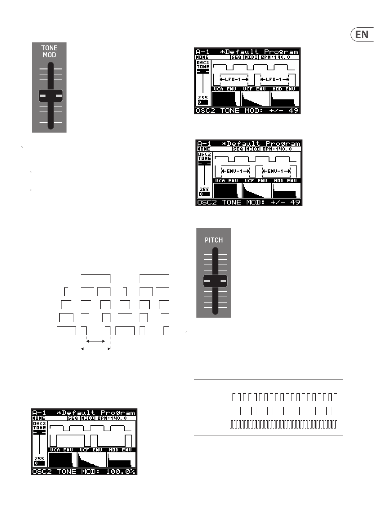
63 DeepMind 12D User Manual
8.3.6 OSC 2 TONE MOD FADER
• The OSC 2 TONE MOD fader controls the TONE MODULATION of the OSC2
SQUARE waveform. The TONE MOD SOURCE is selected in the OSC2
PARAMETERS page of the OSC EDIT menu, described later in this section.
• When the TONE MOD source is set to MANUAL, the fader controls the
TONE MODULATION.
• When the TONE MOD source is set to any of the modulation sources, the
fader controls the depth of TONE MODULATION.
TONE MODULATION can be used in many ways, for example: to create a
double phasing eect, or used when creating complex string-type sounds.
The harmonic struc ture of the OSC changes considerably when using TONE
MODULATION, and the results can of ten have a metallic quality.
Note: for LFO sources, the TONE MOD fader is used to adjust the amount of
modulation from 0 to +/- 49 % .
Note: for ENVELOPE sources, the TONE MOD fader is used to adjust the
amount of modulation from 0 to +/- 49%.
8.3.7 OSC 2 PITCH FADER
As you increase the amount of TONE MODULATION, the positive and negative
parts of the cycle are split by a pulse. The further you increase the fader,
the width of the pulse increases.
TONE MODULATION
50%
62.5%
75%
87.5%
100%
60%
100%
The TONE MOD range is from 50% (symmetrical square-wave) to 100%
(pulse interrupt is 60% of half cycle). The default TONE MOD setting is 50%.
The fader position, current value, and stored value for the TONE MOD fader is
shown on the PROG screen. There is also a visualization of the waveform as
shown below:
• The OSC 2 PITCH fader controls the PITCH of the OSC 2 SQUARE waveform,
relative to the pitch of OSC1 (which is set by the keys that you play on the
keyboard). The pitch can be tuned to match the pitch of OSC1, or oset
slightly to create a wider sound, or oset more to create harmonic overtones.
As you increase/decrease the PITCH fader, the pitch of the oscillator will
increase/decrease.
OSC 2 PITCH
0 (KEY PITCH)
-12 SEMITONES
+12 SEMITONES
The OSC 2 PITCH range is from -12.0 semitones to +12.0 semitones.
The default OSC 2 PITCH setting is 0 semitones (= OSC 1).
Page 64

64 DeepMind 12D User Manual
The fader position, current value, and stored value for the OSC 2 PITCH fader
is shown on the PROG screen. There is also a visualization of the pitch setting
as shown below:
Note: The centre horizontal section of the line shown in the visualization,
highlights the ne resolution that is available around the centre point. Here
the units of adjustment will change from semitones to cents, giving you ne
adjustment when close to the pitch of OSC1.
8.3.8 OSC 2 LEVEL FADER
• The OSC 2 LEVEL fader controls the LEVEL of the OSC 2 SQUARE waveform.
The level setting can be used to adjust the balance between OSC 1 and OSC 2.
OSC 2 LEVEL
0FF
-12.0 dB
0.0 dB
The balance between OSC 1 and OSC 2 when used together, allows you to
increase the sonic palette of the program. Combining oscillators can be
done to create new waveforms and alter the harmonic structure of the
program. By slightly detuning the oscillators, you can create bigger, thicker
sounds. Detuning in small and equal increments will not make a noticeable
dierence to the base pitch of the sound, but as you increase the amount of
detuning it will star t to become noticeable. Detuning can be done in musical
intervals for example a fth, or a seventh, to add harmony to a pad sound, or
even an entire octave to give a bass program a deeper sound.
The OSC 2 LEVEL can be set to O, or its operational range is from -48
to 0.0 dB.
The default OSC 2 LEVEL setting is 0.
The fader position, current value, and stored value for the OSC 2 LEVEL fader
is shown on the PROG screen. There is also a visualization of the waveform as
shown below.
Note: It is important to note that the visualization shows the combination of
OSC 1 and OSC 2.
Page 65

65 DeepMind 12D User Manual
8.3.9 OSC SYNC SWITCH
ON=SYNC ACTIVE
• The SYNC switch controls the synchronisation of the oscillators.
The OSC 1 pitch is set by the keys that you play, and the OSC 2 pitch may be
tuned to (or detuned from) this frequency. By applying hard synchronisation
of OSC 2 to OSC1, every time the OSC 1 cycle starts again, the OSC 2 will be
re-triggered, regardless of its position. If OSC 2 is tuned to a lower frequency
than OSC 1 it will be re-triggered before it completes an entire cycle, and if
it is tuned to a higher frequency it will be re-triggered during a later cycle.
This ensures that the OSCs are playing at the same frequency, however the
irregular cycle of OSC 2 can create complex timbres and rich harmonies.
OSC SYNC EXAMPLE 1 - OSC2 LOWER FREQUENCY THAN OSC1
OSC 1 (SQR)
MASTER
OSC 2 SYNC OFF
OSC 2 SYNC ON
OSC SYNC EXAMPLE 1 - OSC2 HIGHER FREQUENCY THAN OSC1
OSC 1 (SAW)
MASTER
OSC 2 SYNC OFF
8.3.10 NOISE LEVEL FADER
• The NOISE LEVEL fader controls the LEVEL of the internal NOISE signal.
The noise generator is implemented using analog circuitry and creates
pink noise with a low frequency roll-o designed specically for the
DeepMind 12D. The noise generator is commonly used with non-pitched
sounds or non-pitched components of a sound, for example a snare drum or
an atmospheric sound.
Pink noise contains equal amounts of energy in each octave. As human
hearing is roughly logarithmic, this type of noise sounds as if it has an equal
amount of all frequencies, and it produces a rushing sound similar to that of
a waterfall.
The NOISE LEVEL can be set to O, or its operational range is from -48.1 dB to
0.0 dB. The default NOISE LEVEL setting is 0.
The fader position, current value and stored value for the NOISE LEVEL fader
is shown on the PROG screen. There is also a visualization of the noise signal
as shown below:
OSC 2 SYNC ON
OSC SYNC EXAMPLE 1 - OSC2 LOWER THAN 1/2 OF OSC1
OSC 1 (SQR)
MASTER
OSC 2 SYNC OFF
OSC 2 SYNC ON
Note: If OSC 2 is lower than 1/2 of the frequency of OSC 1, then there will
be no output from OSC 2 when SYNC is ON because the waveform will never
reach its negative cycle.
The OSC SYNC option can be On (the SYNC switch is illuminated) or O. The
default program setting is O.
There is also a visualization of the SYNC waveform as shown below. If you
press the SYNC switch on and o, you will see the eect on the waveform.
Page 66

66 DeepMind 12D User Manual
8.3.11 OSC EDIT SWITCH (OSC 1)
1. To access the OSC1 PARAMETERS EDIT menu, press the OSC EDIT switch once.
FLASHING=EDIT
2. The OSC EDIT switch will then start ashing and the OSC 1 PARAMETERS
menu will appear as shown:
3. To navigate the options in the OSC 1 EDIT menu, use the BANK/UP or
BANK/DOWN switches.
• P.MOD -S RC - This option allows you to select the source for the amount of
PITCH MODULATION from the following:
• LFO-1 - Bipolar use of the LFO 1 waveform.
• LFO-2 - Bipolar use of the LFO 2 waveform.
OSC 1 PITCH MODULATION (LFO AS SOURCE)
OSC 1 (SAW)
LFO (SIN)
PITCH MOD
OSC 1 (SQR)
LFO (SIN)
PITCH MOD
There is also a visualization of the modulation as shown below. The arrows
indicate the polarity of the modulation.
4. Selected parameters are adjusted using the -/NO or +/YES switches, the
rotary knob or the DATA ENTRY fader. The rotary knob has a click which
allows very accurate control. The fader allows rapid adjustment across the
full range.
Note: If you want to access the OSC 2 EDIT menu, press the EDIT
switch again.
Shortcut Note: To quickly change any of the OSC Modulation sources, press
and hold down the OSC EDIT switch, and use the PITCH MOD faders to change
the PITCH MOD sources, or use the PWM fader to change the OSC1 PWM
source, and the TONE MOD fader to change the OSC2 TONE MOD source.
The following options are available in the OSC 1 EDIT menu:
• RANGE - This option allows you to select the base pitch of the OSC as follows:
• 16' - The lowest note on the keyboard (C) is tuned to 16.35 Hz.
• 8' - The lowest note on the keyboard (C) is tuned to 32.7 Hz.
• 4'- The lowest note on the keyboard (C) is tuned to 65.4 Hz.
The default setting for the RANGE is 8'.
• ENV-1 - Unipolar use of the ENV 1 envelope.
• ENV-2 - Unipolar use of the ENV 2 envelope.
• ENV-3 - Unipolar use of the ENV 3 envelope.
OSC 1 PITCH MODULATION AMOUNT (ENVELOPE AS SOURCE)
OSC 1 (SQR)
ENVELOPE
PITCH MOD
ATTACK DECAY
SUSTAIN
RELEASE
Note: In the visualization for ENVELOPE sources, the arrow will only point in
the UP direction indicating that the modulation will be positive from the
base pitch.
Page 67

67 DeepMind 12D User Manual
• LFO-1(Uni) - Unipolar use of the LFO 1 waveform.
• LFO-2(Uni) - Unipolar use of the LFO 1 waveform.
Note: In any of the Unipolar (Uni) modes, the waveform is only used for
positive modulation. This is useful when you want the note to play at the
original frequency, and modulation uses that as a reference point (Unipolar),
rather than have the note modulated to positive and negative
osets (Bipolar).
OSC 1 PITCH MODULATION (BIPOLAR/UNIPOLAR LFO AS SOURCE)
OSC 1 (SAW)
LFO (SQR)
BIPOLAR
OSC 1 WITH
PITCH MOD
OSC 1 (SQR)
LFO (SQR)
UNIPOLAR
OSC 1 WITH
PITCH MOD
The default setting for the P.MOD-SRC is LFO-1.
• LFO-1 - Bipolar use of the LFO 1 waveform. In this mode the PWM fader
is used to adjust the amount of modulation from 0 to +/- 49%.
• LFO-2 - Bipolar use of the LFO 2 waveform. In this mode the PWM fader
is used to adjust the amount of modulation from 0 to +/- 49%.
OSC 1 PULSE WIDTH MODULATION (LFO AS SOURCE)
OSC 1 (SQR)
LFO (SIN)
PWM
Note: When an LFO is used as a PWM source, the arrows indicate the
range of modulation as shown below:
Note: In the visualization for Uni-polar LFO sources, the arrow will only point
in the UP direction indicating that the modulation will be positive from the
base pitch.
• AF T> P.MO D - This option controls how much PITCH MODULATION is
increased by AFTERTOUCH pressure. This allows you to expressively control
the PITCH MODULATION and its eect using key pressure.
The AFT>P.MOD range is from 0-255, and the default setting is 0 (O ).
• WHEEL>P.MOD -This option controls how much PITCH MODULATION depth
is increased by the Mod Wheel position. This allows you to expressively
control the PITCH MODULATION and its eect using the Mod Wheel of your
external keyboard.
The AFT>P.MOD range is from 0-255, and the default setting is 0 (O ).
• PWM-SRC - This option allows you to select the source for the amount of
PULSE WIDTH MODULATION from the following:
• ENV-1 - Unipolar use of the ENV 1 envelope. In this mode the PWM fader
is used to adjust the amount of modulation from 0 to +/- 49%.
• ENV-2 - Unipolar use of the ENV 2 envelope. In this mode the PWM fader
is used to adjust the amount of modulation from 0 to +/- 49%.
• ENV-3 - Unipolar use of the ENV 3 envelope. In this mode the PWM fader
is used to adjust the amount of modulation from 0 to +/- 49%.
OSC 1 PULSE WIDTH MODULATION (ENVELOPE AS SOURCE)
OSC 1 (SQR)
ENVELOPE
PWM
ATTACK DECAY
SUSTAIN
RELEASE
Note: When an ENVELOPE is used as a PWM source, the arrows indicate
the range of modulation as shown below:.
• MANUAL - In this mode, the PWM fader is used to manually adjust the
PULSE WIDTH.
Page 68

68 DeepMind 12D User Manual
• P.MOD MODE - This option allows you to select which oscillators are
controlled by the OSC 1 PITCH MOD fader.
Note: It is useful to have both OSCs responding for eects like tremolo.
• OSC1+2 -Both OSCs have PITCH MODULATION applied to them.
• OSC1 - Only OSC 1 has PITCH MODULATION applied to it.
• KEY-DN-RESET - This option allows you to reset the phase of the oscillator
waveform to start from its reset point each time a key is pressed.
OSC 1 KEY DOWN RESET
OSC 1 (SAW)
KEY-DN-RESET
OFF
KEY-DN-RESET
ON
KEY PRESS KEY PRESS KEY PRESS
The default setting for KEY-DN-RESET is O.
5. To exit the OSC 1 PARAMETERS menu, press the PROG switch to return the
main display, or press the OSC EDIT switch again to continue to the OSC 2
PARAMETERS menu.
8.3.12 OSC EDIT SWITCH (OSC 2)
1. To access the OSC EDIT menu, press the OSC EDIT switch.
FLASHING=EDIT
2. The OSC EDIT switch will then start ashing and the OSC 1 PARAMETERS
menu is then shown.
3. Press the EDIT switch again to show the OSC 2 PARAMETERS menu:
4. To navigate the options in the OSC 2 PARAMETERS menu, use the BANK/UP or
BANK/DOWN switches.
5. Selected parameters are adjusted using the -/NO or +/YES switches, the
rotary knob or the DATA ENTRY fader. The rotary knob has a click which
allows very accurate control. The fader allows rapid adjustment across the
full range.
The following options are available in the OSC 2 EDIT menu:
• RANGE - This option allows you selects the base pitch of OSC2 as follows:
• 16' - The lowest note on the keyboard (C) is tuned to 16.35 Hz.
• 8' - The lowest note on the keyboard (C) is tuned to 32.7 Hz.
• 4'- The lowest note on the keyboard (C) is tuned to 65.4 Hz.
The default setting for the RANGE is 8'.
• P.MOD -S RC - This option allows you to select the source for the amount of
PITCH MODULATION from the following:
• LFO-1 - Bipolar use of the LFO 1 waveform.
• LFO-2 - Bipolar use of the LFO 2 waveform.
OSC 2 PITCH MODULATION AMOUNT (LFO AS SOURCE)
OSC 2
LFO (SIN)
PITCH MOD LOW
PITCH MOD MED
PITCH MOD HIGH
Page 69

69 DeepMind 12D User Manual
There is also a visualization of the modulation as shown below. The
arrows indicate the polarity of the modulation.
• ENV-1 - Bipolar use of the ENV 1 envelope.
• ENV-2 - Bipolar use of the ENV 2 envelope.
• ENV-3 - Bipolar use of the ENV 3 envelope.
OSC 2 PITCH MODULATION AMOUNT (ENVELOPE AS SOURCE)
OSC 1 (SQR)
ATTACK DECAY
ENVELOPE
PITCH MOD
SUSTAIN
RELEASE
Note: In the visualization for Uni-polar LFO sources, the arrow only
points in the UP direction, indicating that the modulation will be
positive from the base pitch.
The default setting for the P.MOD-SRC is LFO-1.
• AF T> P.MO D - This option controls how much PITCH MODULATION is
increased by AFTERTOUCH pressure. This allows you to expressively control
the PITCH MODULATION and its eect using key pressure.
The AFT>P.MOD range is from 0-255, and the default setting is 0 (O ).
• WHEEL>P.MOD - This option controls how much PITCH MODULATION depth
is increased by the Mod Wheel position. This allows you to expressively
control the PITCH MODULATION and its eect using the Mod Wheel of your
external keyboard.
The MOD WHEEL>P.MOD range is from 0-255, and the default setting
is 0 (O).
Note: In the visualization for ENVELOPE sources, the arrow will only
point in the UP direction indicating that the modulation will be positive
from the base pitch.
• LFO-1(Uni) - Unipolar use of the LFO 1 waveform.
• LFO-2(Uni) - Unipolar use of the LFO 1 waveform.
Note: In any of the Unipolar (Uni) modes, the waveform is only used for
positive modulation.
OSC 2 PITCH MODULATION (UNIPOLAR LFO AS SOURCE)
OSC 1 (SQR)
LFO (SIN)
UNIPOLAR
PITCH MOD
• T.MO D-SRC - This option allows you to select the source for the amount of
TONE MODULATION from the following:
• MANUAL - The TONE MOD fader is used to manually adjust the PWM.
• LFO-1 - Bipolar use of the LFO 1 waveform. In this mode the TONE MOD
fader is used to adjust the amount of modulation from 0 to +/- 49%.
• LFO-2 - Bipolar use of the LFO 2 waveform. In this mode the TONE MOD
fader is used to adjust the amount of modulation from 0 to +/- 49%.
OSC 2 TONE MODULATION (LFO AS SOURCE)
OSC 2 (SQR)
LFO (SIN)
TONE MOD
Note: When an LFO is used as a TONE MOD source, the arrows indicate
the range of modulation as shown below:
Page 70

70 DeepMind 12D User Manual
• ENV-1 - Bipolar use of the ENV 1 envelope. In this mode the TONE MOD
fader is used to adjust the amount of modulation from 0 to +/- 49%.
• ENV-2 - Bipolar use of the ENV 2 envelope. In this mode the TONE MOD
fader is used to adjust the amount of modulation from 0 to +/- 49%.
• ENV-3 - Bipolar use of the ENV 3 envelope. In this mode the TONE MOD
fader is used to adjust the amount of modulation from 0 to +/- 49%.
OSC 2 TONE MODULATION (ENVELOPE AS SOURCE)
OSC 2 (SQR)
ENVELOPE
TONE MOD
ATTACK DECAY
SUSTAIN
RELEASE
Note: When an ENVELOPE is used as a TONE MOD source, the arrows
indicate the range of modulation as shown below:
8.4 POLY
The POLY section is where you can control all settings related to the POLYPHONY,
PITCH, and POLY CHAIN operation of the DeepMind 12D. The available options
allow you to be highly creative in your use of the polyphonic, unison, and
monophonic capabilities of the voice structure.
POLY EDIT menu page 1 allows access to the VOICE parameters. Having 12 voices
gives you the ability to play 12 simultaneous notes, allowing the creation of large
chords, or being able to play complex sequences without needing to worry about
a note being cut o because there are not enough voices.
When playing voices in unison, you also have the ability to de-tune the voices.
POLY EDIT menu page 2 allows access to all settings related to PITCH
management, including transposition, portamento, pitch bend, and tuning.
POLY EDIT menu page 3 allows access to all settings related to setting up a POLY
CHAIN, where multiple DeepMind units can be used to increase the number of
voices. There are also settings that allow the setting up of a keyboard split with 2
or more DeepMind units.
8.4 .1 UNISON DETUNE FADER
6. To exit the OSC EDIT menu, press the PROG switch or the OSC EDIT
switch again.
• The UNISON DETUNE fader controls how much detuning is applied across
voices when using any of the UNISON modes. The UNISON DETUNE can be
used to create thicker and richer sounds. This is a powerful aspect of the
DeepMind 12D architecture. Having 12 independent analog voices can make
some extremely luxurious and sonically gigantic sounds.
When UNISON DETUNE is applied, up to +/- 50 cents of tuning is spread over
the number of voices used in UNISON.
The UNISON DETUNE range is from +/-0.0 cents to 50.0 cents, and the default
setting is 0.0 cents (O ).
Note: When using UNISON DETUNE in combination with the OSC KEYDOWN
RESET setting (in the OSC1 EDIT menu), you will hear the eects of phase
drift much more clearly, as the OSCs will all start from the same point on
their waveforms.
The fader position, current value, and stored value for the UNISON DETUNE
fader are shown on the PROG screen when the fader has been moved. There
is also a visualization of the detuning amount as shown below:
Page 71
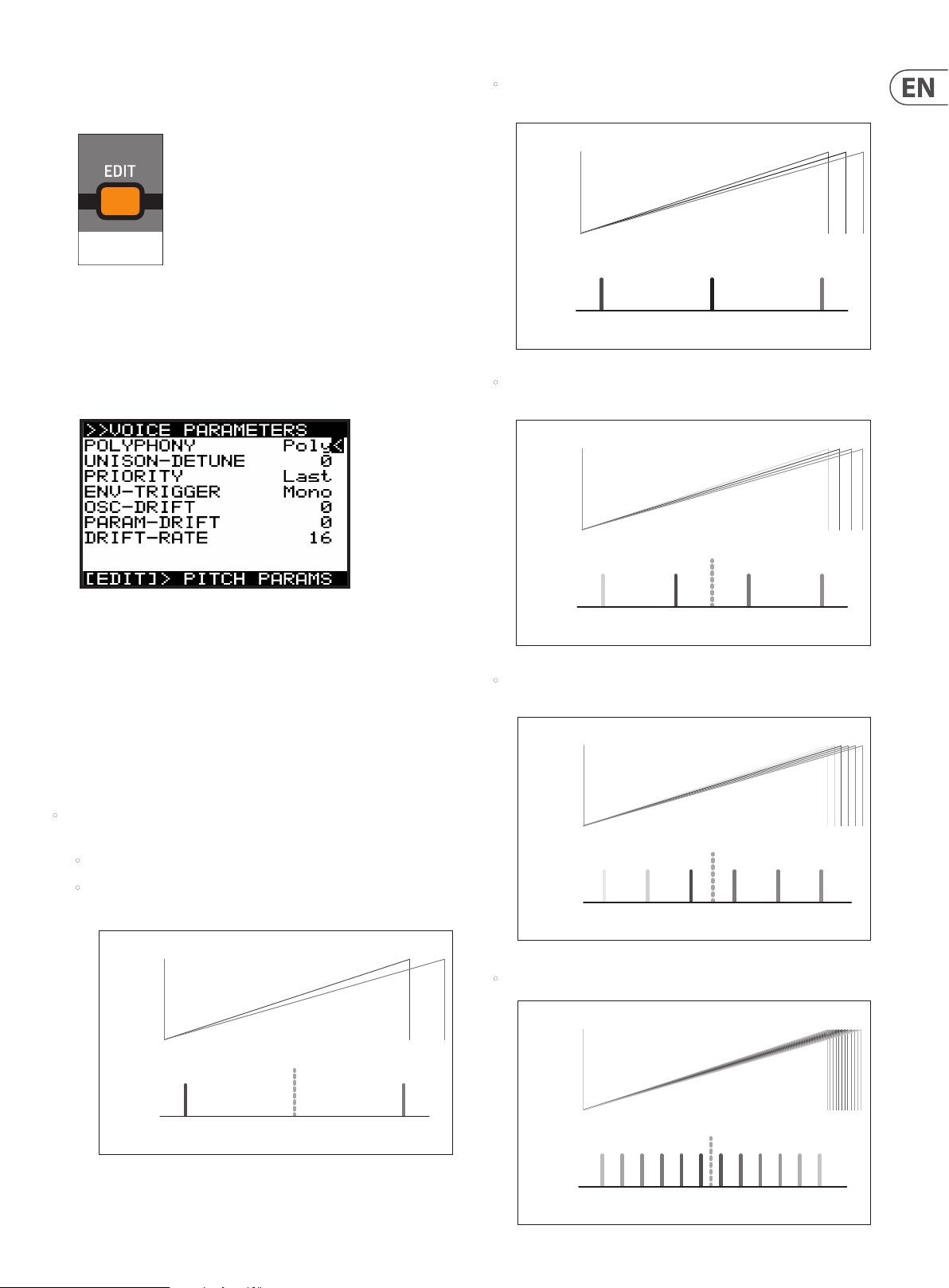
71 DeepMind 12D User Manual
8.4.2 POLY EDIT SWITCH
1. To access the POLY EDIT menu, press the POLY EDIT switch.
FLASHING=EDIT
2. The POLY EDIT switch will then start ashing and the VOICE PARAMETERS
menu will appear. Press it again to reach the PITCH PARAMETERS menu, and
again to reach the CHAIN PARAMETERS menu.
8.4.3 VOICE PARAMETERS MENU
This is the VOICE PARAMETERS menu:
3. To navigate the options in the VOICE PARAMETERS menu, use the BANK/UP
or BANK/DOWN switches.
• Unison-3 - The next available three voices are allocated to each note
played. Detuning is applied as shown below:
UNISON 3
UNISON 3
WAVEFORM
ROOT NOTE
FREQUENCY
UNISON 3
SPECTRUM
1 2 3
MAX -VE
DETUNE
MAX +VE
DETUNE
• Unison-4 - The next available four voices are allocated to each note
played. Detuning is applied as shown below:
UNISON 4
UNISON 4
WAVEFORM
ROOT NOTE
UNISON 4
1 2 3 4
SPECTRUM
MAX -VE
DETUNE
FREQUENCY
MAX +VE
DETUNE
4. Selected parameters are adjusted using the -/NO or +/YES switches, the
rotary knob or the DATA ENTRY fader. The rotary knob has a click which
allows very accurate control. The fader allows rapid adjustment across the
full range.
Note: At this point if you wish to access the PITCH PARAMETERS menu, press
the EDIT switch again.
The following options are available in the VOICE PARAMETERS menu:
• POLYPHONY - This allows you to choose how the DeepMind 12D voices are
allocated from one of the following options:
• Poly - A single voice is allocated to each note.
• Unison-2 - The next available two voices are allocated to each note
played. Detuning is applied as shown below:
UNISON 2
UNISON 2
WAVEFORM
ROOT NOTE
FREQUENCY
UNISON 2
SPECTRUM
1 2
MAX -VE
DETUNE
MAX +VE
DETUNE
• Unison-6 - The next available six voices are allocated to each note
played. Detuning is applied as shown below:
UNISON 6
UNISON 6
WAVEFORM
ROOT NOTE
FREQUENCY
UNISON 6
SPECTRUM
1 2 3 4 5 6
MAX -VE
DETUNE
MAX +VE
DETUNE
• Unison-12 - All 12 voices are allocated to each note played
UNISON 12
UNISON 12
WAVEFORM
ROOT NOTE
FREQUENCY
UNISON 12
SPECTRUM
2 4 61 3 5 7 98 11 1210
MAX -VE
DETUNE
MAX +VE
DETUNE
Page 72

72 DeepMind 12D User Manual
• Mono - The same voice is allocated to every note played.
• Mon o-2 - The same two voices are allocated to each note played. Voices
are spread in the same way as Unison-2 mode.
• Mono -3 - The same three voices are allocated to each note played.
Voices are spread in the same way as Unison-3 mode.
• Mono-4 - The same four voices are allocated to each note played. Voices
are spread in the same way as Unison-4 mode.
• Mono-6 -The same six voices are allocated to each note played. Voices
are spread in the same way as Unison-6 mode.
• Poly-6 - A single voice is allocated to each note played, but polyphony is
limited to the next available six notes.
• Poly-8 - A single voice is allocated to each note played, but polyphony is
limited to the next available eight notes.
Note: When an even number of voices are used (Unison2/4/6/12, Mono
2/4/6), the voices are spread across the spectrum evenly, which means
the root note is not actually played. However if an odd number of voices
are used, when the voices are spread across the spectrum, then one
voice will be playing the root note.
• UNISON DETUNE - This option is the same as the UNISON DETUNE fader on
the surface. Any changes on the surface will be reected here.
The UNISON DETUNE range is from +/-0.0 cents to 50.0 cents (0 to 255), and
the default setting is 0.0 cents (O).
• PRIORITY - When in monophonic mode, or when more notes are played
than there are voices available (due to polyphonic/unison settings), this
mode controls which notes are prioritized.
• Lowest - In lowest note priority, when a newly requested note is lower
in pitch than the notes currently being played, then it will be given
priority and will steal the voice that is playing the highest note.
• Highest - In highest note priority, when a newly requested note is
higher in pitch than the notes currently being played, then it will be
given priority and will steal the voice that is playing the lowest note.
• Last - In this mode the notes are prioritized based on the order in
which they are played. When a newly requested note is triggered while
all voices are playing, it steals the voice used by the note played least
recently. The default PRIORITY setting is Last.
• OSC-DRIFT - This option allows you to recreate the oscillator tuning drift
that vintage analog synthesizers have.
As you increase the OSC-DRIFT value, the pitch of the oscillators will be slowly
modulated at random.
OSC-DRIFT is applied to both OSC 1 and OSC 2.
The OSC-DRIFT range is from 0 to 255, and the default setting is 0 (no drift).
• PARAM-DRIFT - This option allows you to recreate the drift that many
parameters in a vintage analog synthesizers have.
As you increase the PARAM-DRIFT value, the drift distances will increase.
Note: The parameters which DRIFT is applied to are:
• OSC1 PITCH MOD, OSC1 PWM, OSC2 PITCH MOD, OSC2 TONE MOD,
• VCF FREQ, VCF RES, VCF ENV DEPTH, VCF LFO DEPTH, VCA ENV DEPTH,
• MOD ENV DEPTH
The PARAM-DRIFT range is from 0 to 255, and the default setting is 0.
• DRIF T-RATE - This controls the RATE at which the OSC-DRIFT and
PARAM-DRIFT operate. It is important to note that each voice has
independent random DRIFT generators for the OSC-DRIFT and the
PARAM-DRIFT, to more closely replicate the characteristics of a
vintage synthesizer.
The rate is controlled by a random timer which generates a ramp
between a multiplier of 1x and a multiplier of 2x the rate set by the
DRIFT-RATE parameter.
The OSC-DRIFT range is from 0 (25 ms-50 ms) to 255 (2.5 s-5.0 s). The default
OSC-DRIFT setting is 0.
To summarize, if the DRIFT-RATE is at 0, each “drift” will be a random time
between 25 and 50 ms, and then the parameter drifts to another random
value. At 255, each “drift” will be a random time between 2.5 s and 5.0 s and
then the parameter drifts to another random value.
5. To exit the VOICE PARAMETERS menu, press the PROG switch to return
the main display, or press POLY EDIT once more to reach the PITCH
PARAMETERS menu.
Note: PRIORITY is not available as an option when in POLY CHAIN mode
because excess notes are played on other DeepMind 12D units in the
Poly Chain. (See the CHAIN PARAMETERS MENU).
• ENV-TRIGGER - The envelopes can be triggered in dierent ways. This
allows you to choose a mode from the following options:
• Mono - In this triggering mode, the voice will start its attack stage
from the current envelope level, that is, its last level from the previous
release. The default triggering mode is Mono.
• Retrigger - In this triggering mode, the envelope will be reset to zero
and then start its attack stage.
• Legato - In this triggering mode, the envelope does not re-trigger
when a new note is played. The only time the envelope will start the
attack stage again is once the note is released.
• One-shot - In this triggering mode, the envelope will be reset to zero
and then start its attack stage. Once the decay phase is complete, the
envelope will jump immediately to its release stage (that is, there is no
sustain phase).
Page 73

73 DeepMind 12D User Manual
8.4.4 PITCH PARAMETERS MENU
1. To access the PITCH PARAMETERS menu, press the POLY EDIT switch.
FLASHING=EDIT
2. The POLY EDIT switch will then start ashing and the VOICE PARAMETERS
menu is then shown. Press the EDIT switch again to show the PITCH
PARAMETERS menu:
CAUTION: If you ever suspect that your DeepMind 12D seems to be out of tune, it
is a good idea to check the values for TRANSPOSE and GLOBAL-TUNE in this menu.
• Fix-Rate - In this mode the slide time between played notes is a xed
rate, regardless of overlapping notes. The pitch distance from note to
note will aect the time it takes to slide between notes. The sliding
between notes is linear.
• Fix-Fing - In this mode the slide time between played notes is a xed
rate. The pitch distance from note to note will aect the time it takes
to slide between notes. Sliding is only applied when notes overlap. The
sliding between notes is linear.
• Exp - In this mode the slide time between played notes is a xed rate.,
regardless of overlapping notes. The pitch distance from note to note
will aect the time it takes to slide between notes. The sliding between
notes is exponential.
• Exp-Fing - In this mode the slide time between played notes is a xed
rate. The pitch distance from note to note will aect the time it takes
to slide between notes. Sliding is only applied when notes overlap. The
sliding between notes is exponential.
• Fixed+2 - In this mode the note always starts at a pitch two semitones
above the played note, regardless of overlapping notes or pitch distance.
The sliding between notes is exponential.
• Fixed-2 - In this mode the note always starts at a pitch two semitones
below the played note, regardless of overlapping notes or pitch
distance. The sliding between notes is exponential.
• Fixed+5 - In this mode the note always starts at a pitch ve semitones
above the played note, regardless of overlapping notes or pitch distance.
The sliding between notes is exponential.
3. To navigate the options in the PITCH PARAMETERS menu, use the BANK/UP
or BANK/DOWN switches.
4. Selected parameters are adjusted using the -/NO or +/YES switches, the
rotary knob or the DATA ENTRY fader. The rotary knob has a click which
allows very accurate control. The fader allows rapid adjustment across the
full range.
The following options are available in the PITCH PARAMETERS menu:
• TRANSPOSE - This option allows you to TRANSPOSE notes played on the
keyboard. The notes played can be transposed in steps of single semitones.
The TRANSPOSE range is from -48 to +48, and the default TRANSPOSE
setting is 0. For example, a transpose of -7 would mean that all played keys
would be transposed down by seven semitones.
• PORTA-TIME - This option is the same as the PORTAMENTO knob on the
surface. Any changes to the knob will be reected here.
The PORTAMENTO function makes the pitch of a note glide up or down from
the previously played note. The PORTAMENTO knob controls the time taken
to transition from the previous note to the currently played note.
The PORTAMENTO range is from 0 (0.00s - instant change of note) to 255
(10.00s of glide). The default PORTAMENTO setting is 0 (0.00s/O).
• PORTA-MODE - This option allows you to congure the PORTAMENTO
function to operate in dierent ways depending on your requirements.
The options are:
• Fixed-5 - In this mode the note always starts at a pitch ve semitones
below the played note, regardless of overlapping notes or pitch
distance. The sliding between notes is exponential.
• Fixed+12 - In this mode the note always starts at a pitch twelve
semitones (one octave) above the played note, regardless of overlapping
notes or pitch distance. The sliding between notes is exponential.
• Fixed-12 - In this mode the note always starts at a pitch twelve
semitones (one octave) below the played note, regardless of
overlapping notes or pitch distance. The sliding between notes
is exponential.
• Fixed+24 - In this mode the note always starts at a pitch twenty-
four semitones (two octaves) above the played note, regardless
of overlapping notes or pitch distance. The sliding between notes
is exponential.
• Fixed-24 - In this mode the note always starts at a pitch twenty-
four semitones (two octaves) below the played note, regardless
of overlapping notes or pitch distance. The sliding between notes
is exponential.
• Normal - In this mode the slide time between played notes is a xed
time, regardless of overlapping notes or pitch distance. The sliding
between notes is linear.
• Fingered - In this mode the slide time between played notes is a xed
time, regardless of pitch distance. Sliding is only applied when notes
overlap. The sliding between notes is linear.
Page 74

74 DeepMind 12D User Manual
• PORTA-OSC-BAL - This option allows you to balance the application of
PORTA-TIME (the slide time between played notes) between OSC1 and OSC2.
When a positive setting is chosen, the OSC 1 PORTA-TIME will decrease. At
its maximum value (127), the OSC 1 PORTA-TIME will be zero, and the pitch
change will happen immediately (no sliding).
When a negative setting is chosen, the OSC 2 PORTA-TIME will decrease. At
its minimum value (-127) the OSC 2 PORTA-TIME will be zero, and the pitch
change will happen immediately (no sliding).
PORTAMENTO BALANCE
Start Pitch
PITCH (Hz)
Stop Pitch
Start Pitch
PITCH (Hz)
PORTA-BAL 0
OSC 1 and OSC 2
TIME (seconds)
PORTA-BAL +VE
OSC 1 OSC 2
8.4.5 CHAIN PARAMETERS MENU
Use the POLY EDIT switch to access the CHAIN PARAMETERS menu. This menu is
used to set up a POLY CHAIN, a system where multiple DeepMind 12D, DeepMind
12, and DeepMind 6 synthesizers can be connected together, enabling more than
12-Voice Polyphony.
This menu can also be used to set up a KEYBOARD SPLIT if you have two or more
DeepMind units.
A single DeepMind 12D unit has a maximum of 12 voices that can play at any one
time (12-Voice Polyphony). If further voices are attempted than are available,
then information is lost. (How this is handled for a single unit, is described in the
PRIORITY section of the VOICE PARAMETERS menu.
In order to increase the number of voices that can play at any one time, you can
add additional DeepMind synthesizers into your system and set up a POLY CHAIN
using the CHAIN PARAMETERS page of the POLY EDIT menu.
Note: If you are just using one DeepMind unit, then there is no need to use this
menu, although it is a good idea to know its details, as the chosen settings will
aect normal operation, and it may give you ideas for future expansion.
Stop Pitch
TIME (seconds)
Start Pitch
PITCH (Hz)
Stop Pitch
PORTA-BAL –VE
OSC 2 OSC 1
TIME (seconds)
The PORTA-OSC-BAL parameter ranges from -128 to 127, and the default
setting is 0.
• P.BEND RANGE+ - This option allows you to set the upper limit of the Pitch
Wheel of your keyboard. The pitch bend depth parameters are bi-polar.
The P.BEND RANGE+ parameter can be varied from -24 to +24 (notes).
The default P.BEND RANGE+ setting is +2 (notes).
• P.BEND RANGE- - This option allows you to set the lower limit of the Pitch
Wheel of your keyboard. The pitch bend depth parameters are bi-polar, so
moving the pitch wheel downwards can be made to pitch the voices up, for
example by a dierent depth to the positive depth.
The P.BEND RANGE- parameter can be varied from -24 to +24 (notes).
The default P.BEND RANGE- setting is -2 (notes).
• GLOBAL-TUNE - This option allows you to adjust the GLOBAL TUNING for
the synthesizer. The range is -128 to 127.
CAUTION: If you ever suspect that your DeepMind 12D seems to be out of
tune, it is a good idea to check that the GLOBAL-TUNE is set to 0.
FLASHING=EDIT
1. Press the POLY EDIT switch and it will start ashing, and the VOICE
PARAMETERS menu will appear.
2. Press the EDIT switch twice more to show the CHAIN PARAMETERS menu:
3. To navigate the options in the CHAIN PARAMETERS menu, use the BANK/UP
or BANK/DOWN switches.
4. Selected parameters are adjusted using the -/NO or +/YES switches, the
rotary knob or the DATA ENTRY fader. The rotary knob has a click which
allows very accurate control. The fader allows rapid adjustment across the
full range.
The following options are available in this menu. (Further details and examples of
the actual operation are shown later in this section.)
• POLY-CHAIN - Select ON if you are using more than one DeepMind
synthesizer and you would like to set up a POLY CHAIN.
• PROGRAM LINK - Select ON if you want the other DeepMind units in the
POLY CHAIN to automatically change to the same program as playing in the
rst DeepMind unit. This option is only available when POLY CHAIN is ON.
5. To exit the PITCH PARAMETERS menu, press the PROG switch to return to
the main display, or press the POLY EDIT switch again to enter the CHAIN
PARAMETERS menu.
• KEY RANGE - Select ON if you have two DeepMind synthesizers and would
like to set up a KEYBOARD SPLIT. One DeepMind can operate one side of the
keyboard, and the other DeepMind can control the other side. Each side of
the split can have its own program.
Page 75

75 DeepMind 12D User Manual
• RANGE-LOWER - This option allows you to set up the lower key for your
KEYBOARD SPLIT. You can either set the value manually, using the -/NO and
+/YES switches, rotary knob, or DATA ENTRY fader, or you can HOLD down
the EDIT switch in the POLY section, and then press the key on the keyboard
that you want to be the lowest key in the range. This option is only available
if KEY RANGE is ON.
• RANGE-UPPER - This option allows you to set up the upper key for your
KEYBOARD SPLIT. You can either set the value manually, using the -/NO and
+/YES switches, rotary knob, or DATA ENTRY fader, or you can HOLD down
the EDIT switch in the POLY section, and then press the key on the keyboard
that you want to be the upper key in the range. This option is only available
if KEY RANGE is ON.
SETTING UP A POLYCHAIN
Please see the hookup diagram in this manual that shows the typical connections
for a POLY CHAIN.
1. MIDI connections - Multiple DeepMind synthesizers can be connected
together in a POLY CHAIN using MIDI 5-pin cables as follows:
• MIDI OUT of DeepMind 1 connected to MIDI IN of DeepMind 2
• MIDI OUT of DeepMind 2 connected to MIDI IN of DeepMind 3
• and so on.
Important settings
In order to successfully set up a POLY CHAIN, there are a number of settings that
need to be checked and adjusted in various menus as follows:
1. If you have a DeepMind 12 or DeepMind 6, make it the rst unit in the chain,
as it has its own keyboard.
2. Make sure that all units are running the latest version of the rmware. You
can view the rmware version in the SYSTEM SETTINGS page of the GLOBAL
menu. (Press GLOBAL a few times until this menu appears, then check that
the versions are the same.)
3. In the CONNECTIVITY page of the GLOBAL menu, make sure the DEVICE ID is
the same for all units.
4. In the MIDI SETTINGS page of the CONNECTIVITY menu:
• Make sure the RX-CHANNEL of each DEEPMIND unit is equal to the
TX-CHANNEL of the preceeding DeepMind unit in the chain.
• MIDI CTRL has 3 options; NRPN, CC, and OFF which aect the operation
of the PROGRAM-LINK. The recommended setting is NRPN, and this is
explained later.
Using the CHAIN PARAMETERS menu
1. To directly access the CHAIN PARAMETERS menu, use the POLY section's EDIT
switch three times and the menu will appear, and the EDIT switch will ash.
1st DeepMind
MIDI IN
2nd DeepMind
MIDI IN
3rd DeepMind
MIDI OUT
MIDI OUT
Note: POLY CHAIN or KEYBOARD SPLIT operation is not available through
USB MIDI or WiFi MIDI.
2. VOICE Priority - The voice priority is set by their position in the MIDI chain:
• DeepMind 1 plays up to a maximum of 12 voices, after which,
DeepMind 2 will begin to play
FLASHING=EDIT
2. Select POLY-CHAIN ON for all units, except there is no need to do this for the
last unit in the MIDI chain.
3. Select PROGRAM-LINK ON if you want to link the program selection of the 1st
unit to automatically change the next unit to the same program. Do this for
all units, except there is no need to do this for the last unit in the MIDI chain.
Leave it OFF if you want the programs to be dierent in each unit.
Note: The last unit in any POLY CHAIN does not need to be set to POLY-CHAIN
ON or PROGRAM-LINK ON, as it is not sending any MIDI out to another unit.
• DeepMind 2 plays up to a maximum of 12 voices, after which,
DeepMind 3 will begin to play
• and so on
3. Audio Connections - The L/R line-level audio output of each DeepMind
unit connects to the line-level inputs of an audio mixer. This allows you to
control the audio mix of all your DeepMind units, adjust levels and EQ etc.
The audio output of the mixer connects to an amplier, or powered monitors
or speakers.
Page 76

76 DeepMind 12D User Manual
OPERATION OF THE POLY CHAIN
4. The rst DeepMind unit will play as normal.
5. The other DeepMind units will come into play whenever the voices exceed
multiples of 12 (or 6 voices if you have a DeepMind 6 in the chain).
6. Use each DeepMind unit's volume control to adjust the levels, and/or adjust
your external mixer as desired.
7. With the PROGRAM-LINK ON, then the rst unit will control the program
playing in the next units in line. Each time you change program on the rst
DeepMind unit, the others in line will change to the same program name,
but with a * next to it.
Note: The program in the other units is just temporary, and the bank and
program number do not change.
8. The POLYPHONY setting of each program will aect how the voices play
within each DeepMind unit. You can experiment with the POLYPHONY
setting in the VOICE PARAMETERS page of the POLY EDIT menu, to become
familiar with your POLY CHAIN setup.
Operation example:
• In the rst DeepMind unit, set POLYPHONY to UNISON-3 and press a key. You
will see 3 Voice LEDs light up per key. So if you press 4 keys, then 12 voices
are in play, and 12 voice LEDS are lit. Now press 1 more key, and you should
see 3 Voice LEDs light up in the 2nd DeepMind unit. This shows that the POLY
CHORD is working.
1 key pressed (Unison-3)
DeepMind 1
DeepMind 2
3 voices
3 voices total
0 voices
The program playing in each unit down the line can be adjusted if desired, or
changed to a dierent program, without aecting the program playing in the
previous unit in line. However, the changes will aect the next unit in line, unless
you turn PROGRAM-LINK o on the unit you are adjusting.
SETTING UP A KEYBOARD SPLIT
You can use 2 or more DeepMind units to set up a KEYBOARD SPLIT. For example:
• One unit can be a DeepMind 12 with its integral keyboard.
• A second unit can be the DeepMind 12D with no keyboard.
• Using the KEY-RANGE setting in the CHAIN PARAMETERS menu, the
DeepMind 12 can play one side of its keyboard with one program,
and the DeepMind 12D can play the other side of the keyboard with a
dierent program.
Note: For a KEYBOARD SPLIT, you would turn the POLY CHAIN setting OFF.
(This also turns the PROGRAM LINK OFF.) In this way, the second unit can play
straight away, as it is not dependent on receiving overow notes from the rst
unit in order to play.
1. MIDI connections - Two DeepMind synthesizers are connected together in
a KEYBOARD SPLIT using a MIDI 5-pin cable as follows:
• MIDI OUT of DeepMind 1 is connected to the MIDI IN of DeepMind 2.
If you want to use a third DeepMind synthesizer for a 3-way KEYBOARD
SPLIT, then connect:
• MIDI THRU of DeepMind 2 to the MIDI IN of DeepMind 3.
1st DeepMind
MIDI OUT
5 keys pressed (Unison-3)
DeepMind 1
DeepMind 2
12 voices
15 voices total
3 voices
To check the PROG-LINK is working:
• Change the program in the rst DeepMind unit, and check that the other
units change to the same program name (with a *).
• If you press any EDIT switch on the other units, you should see their values
change as the program is changed on the rst unit.
If PROG-LINK is ON, the rst DeepMind unit sends a SysEx dump of its EDIT buer
to the other units in line. Depending on the MIDI CTRL setting, these other units
will respond as follows:
• In the MIDI SETTINGS page of the CONNECTIVITY menu:
• If MIDI CTRL is set to NRPN for all units, and PROGRAM-LINK is ON, then
any changes that you make to the rst DeepMind unit will aect the
others in line. (This is the recommended setting.)
• If MIDI CTRL is set to CC for all units, and PROGRAM-LINK is ON, then only
fader changes that you make to the rst DeepMind unit will aect the
others in line.
MIDI IN
2nd DeepMind
MIDI IN
3rd DeepMind
THRU
Note: POLY CHAIN or KEYBOARD SPLIT operation is not available through
USB MIDI or WiFi MIDI.
2. Audio connections - The L/R line-level audio output of each DeepMind
unit connects to the line-level inputs of an audio mixer. This allows you to
control the audio mix of all your DeepMind units, adjust levels and EQ etc.
The audio output of the mixer connects to an amplier, or powered monitors
or speakers.
• If MIDI CTRL is set to OFF for all units, and PROGRAM-LINK is ON, then no
changes that you make to the rst DeepMind unit will aect the others
in line.
Page 77
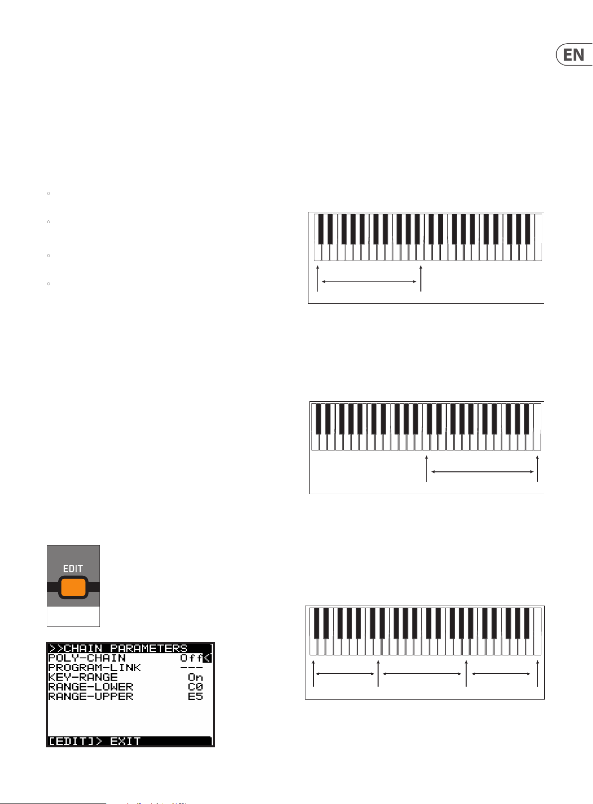
77 DeepMind 12D User Manual
Important settings
In order to successfully set up a KEYBOARD SPLIT, there are a number of settings
that need to be checked and adjusted in various menus as follows:
1. Make sure that all units are running the latest version of the rmware. You
can view the rmware version in the SYSTEM SETTINGS page of the GLOBAL
menu. (Press GLOBAL a few times until this menu appears, then check that
the versions are the same.)
2. In the CONNECTIVITY page of the GLOBAL menu, make sure the DEVICE ID is
the same for all units.
3. In the MIDI SETTINGS page of the CONNECTIVITY menu:
• Make sure RX-CHANNEL and TX-CHANNEL are set to the same channel
number for all units.
• Make sure that MIDI CTRL is set to CC.
4. Using the ARP SETTINGS page of the ARP EDIT menu:
• The rst unit can have its clock set to INTERNAL and the TRANSMIT-
CLOCK set to ON.
• The clock of the second unit can then be set to MIDI (Auto). When set
correctly, the TAP/HOLD button of the second unit will blink in time with
the rst unit's clock.
5. If you have more than one keyboard, for example you have two DeepMind 12
units, you can turn LOCAL OFF on one of them, so its keyboard is no longer
used. This option is in the KEYBOARD SETTINGS page of the GLOBAL menu.
OPERATION WITHOUT THE KEYBOARD SPLIT
6. With two DeepMind synthesizers connected as described above, they can
both play when the keys are played on the keyboard. For example, if the rst
unit is a DeepMind 12 with the keyboard, it will play as normal. The MIDI
connection to the DeepMind 12D desktop model, will allow it to play at the
same time. You can use the volume controls of each unit, and/or the external
mixer to balance the audio output of each unit. Each unit can have a dierent
program playing.
2. Select POLY-CHAIN OFF for each unit. (PROGRAM-LINK is not an available
option when POLY-CHAIN is OFF.)
3. Select KEY-RANGE ON for each unit.
4. You can either set the value of each range manually, using the -/NO and +/
YES switches, rotary knob, or DATA ENTRY fader, or you can HOLD down the
EDIT switch in the POLY section, as described in the details below.
Setting up the rst unit
5. Press and hold the POLY section's EDIT switch on the rst unit, with RANGELOWER selected, and press the lowest key on the keyboard (for example).
6. Press and hold EDIT on the rst unit, with RANGE-UPPER selected, and press
the B below middle C on the keyboard (for example).
1st DeepMind
Lower Upper
Setting up the second unit
7. Press and hold EDIT on the second unit, with RANGE-LOWER selected, and
press the middle C key on the keyboard (for example).
8. Press and hold EDIT on the second unit, with RANGE-UPPER selected, and
press the last key on the keyboard (for example).
7. Once you have tested that both DeepMind units are playing correctly from
the one keyboard, you can set up the KEYBOARD split as follows:
Using the CHAIN PARAMETERS menu to create a KEYBOARD SPLIT
1. To directly access the CHAIN PARAMETERS menu, use the POLY section's EDIT
switch three times and the menu will appear, and the EDIT switch will ash.
Do this for both DeepMind units.
FLASHING=EDIT
2nd DeepMind
Lower Upper
Note: If you see that the setting up of range of this second unit aects the
range of the rst unit, make sure that MIDI CTRL is set to CC and not NRPN.
9. If you have a third DeepMind unit and want to set up a 3-way KEYBOARD
SPLIT, make sure the MIDI IN of the 3rd unit is connected to the MIDI-THRU of
the 2nd unit, and not MIDI OUT.
10. Then set up the 3rd unit's RANGE-LOWER and RANGE-UPPER in the
same way.
1st DeepMind 2nd DeepMind 3rd DeepMind
Upper/LowerUpper/LowerLower
Upper
Page 78
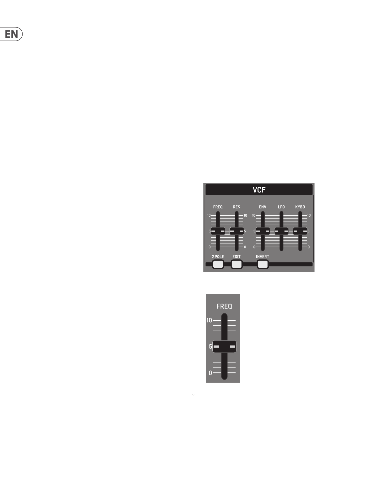
78 DeepMind 12D User Manual
OPERATION OF THE KEYBOARD SPLIT
1. In rst example, the rst DeepMind unit can play the notes that are below
middle C.
2. The second DeepMind unit can play the notes that are middle C and above.
3. Each unit can play its own program, and the volume of the audio output
from each unit can be adjusted with the volume controls, or the external
audio mixer.
4. To exit the KEYBOARD SPLIT mode, turn the KEY-RANGE OFF in each CHAIN
PARAMETERS menu.
8.5 VCF
The VOLTAGE CONTROLLED FILTER (VCF) is an advanced lter designed specically
for the DeepMind 12D. The VCF lter changes the tone color created by the OSCs
and NOISE generator by cutting o, or emphasizing frequencies/harmonics. The
VCF stage allows the low frequencies to pass, and cuts o higher frequencies.
This approach is used by many classic subtractive synthesizers.
The VCF is a fully analog lter, with the ability to be switched from a 2-pole/12 dB
per octave lter to a 4-pole/24 dB per octave lter. The dB per octave refers to the
angle of the lter's slope/response curve.
The VCF also has adjustable resonance which creates a narrow peak around
the lter cut-o frequency. The DeepMind 12D lter is capable of being driven
into self oscillation when the resonance setting is high. Unlike many other
synthesizers, the DeepMind 12D is capable of accurate pitch tracking even when
the lter resonance is pushed to (and past) the point where the lter starts
to self-oscillate. The self-oscillation is tuned so that you can play it as a fully
polyphonic 3rd oscillator across the entire range of playable notes.
The VCF can be modulated dynamically by the VCF Envelope, LFO or Keyboard
Tracking. The VCF Frequency is also available in the Mod Matrix as a destination
where it can be modulated from any of the Mod Matrix sources.
8.5.1 VCF FREQ FADER
• The VCF FREQ fader controls the cut-o frequency of the VCF. The VCF will
begin cutting frequencies below the cut-o frequency and continue to cut
them at a rate depending on the number of poles used.
You can use the lter to sculpt the sonic characteristics of the OSCs and noise
generator, or you can dynamically adjust the fader to create sweeps of the
lter which will create distinctive movement.
Modulating the cut-o frequency with sources such as an envelope
generator, with fast attack settings can help emulate the attack transients of
natural instruments, or be used to creative eect.
Page 79

79 DeepMind 12D User Manual
The diagram below shows the results from high, medium and low settings
of the cut-o frequency when applied to the SAWTOOTH and
SQUARE waveforms.
VCF FREQUENCY
SAWTOOTH SQUARE
HIGH
LEVEL (dB)
FREQUENCY (Hz)
-3 dB
MED
LEVEL (dB)
FREQUENCY (Hz)
-3 dB
LOW
LEVEL (dB)
FREQUENCY (Hz)
The VCF FREQ range is from 50.0 Hz to 20000.0 Hz. The default VCF
FREQUENCY setting is 20000.0 Hz (fully open).
The fader position, current value and stored value for the VCF FREQ fader is
shown on the PROG screen. There is also a visualization of the lter cur ve as
shown below.
Note: The slope of the lter will update depending on the use of a 2-pole or
4-pole conguration.
8.5.2 VCF RES FADER
• The VCF RES fader controls the resonance of the lter. When resonance is
increased, the frequencies/harmonics/partials around the cut-o frequency
are emphasized. The resonance along with the lter slope help dene the
character of the lter.
The DeepMind 12D lter is capable of being driven into self oscillation. Unlike
many other synthesizers, the DeepMind 12D can guarantee an accurate pitch
even when the lter resonance is pushed to (and past) the point where the
lter starts to self-oscillate. When using this self-oscillating feature of the
VCF as a sound source, the VCF calibration ensures the correct response when
playing the entire scale of the keyboard. For more information please consult
the section on calibration later in this document.
VCF RESONANCE
SAWTOOTH SQUARE
LOW
LEVEL (dB)
FREQUENCY (Hz)
MED
LEVEL (dB)
FREQUENCY (Hz)
HIGH
LEVEL (dB)
FREQUENCY (Hz)
The VCF RES range is from 0.0% to 100.0%. The default VCF RES setting
is 0.0%.
The fader position, current value and stored value for the VCF RES fader is
shown on the PROG screen. There is also a visualization of the resonance as
shown below:
Page 80

80 DeepMind 12D User Manual
8.5.3 2-POLE SWITCH
ON=2P / OFF=4P
• This switch controls the conguration of poles used in the VCF. The
number of poles used in the lter determines the angle of the lters slope/
response curve.
The VCF uses 4-poles, but can be switched into 2-pole operation. If
congured for 4-pole operation the low-pass lter rolls o signals above
the cut-o frequency at a rate of 24 dB/octave. When congured for 2-pole
operation the low-pass lter rolls o signals above the cut-o frequency at a
rate of 12 dB/octave.
This can be useful to control the sonic character of the lter, as the 2-pole
mode will allow more of the signal above the cut-o frequency to pass and
sound brighter / more natural. The 4-pole mode allows less of the signal
above the cut-o frequency to pass and sounds deeper/ more unusual.
VCF POLES ( CUT OFF SLOPE)
8.5.4 VCF EDIT SWITCH
FLASHING=EDIT
1. To access the VCF menu press the VCF EDIT switch.
2. The VCF EDIT switch will then start ashing and the VCF PARAMETERS menu
is then shown:
3. To navigate the options in the VCF PARAMETERS menu, use the BANK/UP or
BANK/DOWN switches.
LEVEL (dB)
4-Pole 2-Pole
FREQUENCY (Hz)
The 2-POLE conguration can be On (2-Pole) or O (4-Pole). The default
program setting is O (4-Pole).
4. Selected parameters are adjusted using the -/NO or +/YES switches, the
rotary knob or the DATA ENTRY fader. The rotary knob has a click which
allows very accurate control. The fader allows rapid adjustment across the
full range.
The following options are available in the VCF PARAMETERS menu:
• BASS-BOOST - This option engages an analog bass boost circuit. This set ting
follows the setting of the BOOST switch below the HPF Fader.
• VELOCITY-SENS - This option controls how much the velocity at which you
strike the keys will aect how much VCF envelope modulation is applied.
The harder you strike the keys, the more the lter will open and the
brighter the sound will become (unless the operation is inverted using the
INVERT switch).
The VELOCITY-SENS range is from 0 to 255, and the default setting is 128.
• P.BEND-FREQ - This option controls how much your external keyboard's
Pitch Bend Wheel position will aect the cut-o frequency. The further
you move the wheel forward from its central position, the more the lter
will open and the brighter the sound will become, the further you move
the wheel backward from its central position, the more the lter will close,
and the darker the sound will become.
The P.BEND-FREQ range is from 0 to 255, and the default setting is 128.
• LFO-SELECT - This option allows you to select which LFO is assigned to the
VCF LFO MODULATION FADER, either LFO 1 or LFO 2.
The default setting is LFO 2, which allows you to use LFO 1 for voice
modulation and keep the functionality separated. You can use the same LFO
to modulate the OSC and VCF if you desire.
• AFT-LFO-DEPTH - This option controls how much the Aftertouch pressure of
your keyboard will increase the LFO MODULATION DEPTH. This allows you to
add LFO modulation of the lter frequency expressively while you play.
The AFT-LFO-DEPTH range is from 0 to 255, and the default setting is 0.
Page 81

81 DeepMind 12D User Manual
• MW-LFO-DEPTH - This option controls how much the external keyboard's
Mod Wheel position will aect the LFO MODULATION DEPTH. This allows you
to add LFO modulation of the lter frequency expressively while you play.
The MW-LFO-DEPTH range is from 0 to 255, and the default setting is 0.
• LPF-TYPE - This option is the same as the 2-POLE switch on the surface. Any
changes on the surface will be reected here.
The LPF-TYPE conguration can be 2-POLE or 4-POLE, and the default setting
is 4-POLE.
8.5.5 VCF ENV FADER
8.5.6 INVERT SWITCH
ON=INVERTED
• This switch controls the polarity of the VCF ENVELOPE modulation. When the
switch is on, the polarity of the envelope will be inverted.
It is advised to set the VCF ENV fader to a lower level when using normal
polarity, and set it to a higher level when using the INVERT function of the
VCF ENVELOPE MODULATION parameter.
The INVERT switch can be set to On or O, and the default program setting
is On.
• The VCF ENV fader controls the amount of VCF ENVELOPE modulation that
will be applied to the cut-o frequency value.
When the cut-o frequency is modulated by the VCF ENVELOPE, each note
will be aected by the ADSR (and Curves) stages for the VCF ENVELOPE.
You can use this to apply subtle or aggressive modulation to the harmonic
characteristics of each note played for the duration they are playing.
When modulating the cut-o frequency using the VCF ENVELOPE, it is
advised to set the VCF ENV fader to a lower level when using normal polarity,
and set it to a higher level when using the INVERT function of the VCF
ENVELOPE MODULATION parameter.
When no ENV MODULATION is applied, the lter cut-o frequency will stay
xed (unless other sources of modulation are applied).
The cut-o frequency setting can limit the modulation from the VCA
ENVELOPE. If the VCF FREQ fader is already at its maximum setting, and
the lter is already wide open, then no positive modulation can take the
cut-o frequency higher. This is also true for negative values when the VCF
ENVELOPE is inverted.
The VCF ENV range is from 0.0% to 100.0%, and the default setting is
0.0% (O ).
The fader position, current value, and stored value for the VCF ENV fader
is shown on the PROG screen. There is also a visualization of the envelope
amount (the arrow pointing to the right) as shown below:
Note: When you invert the polarity of the envelope, the arrow indicating the
envelope modulation will be reversed and point to the left to indicate
negative modulation.
Page 82

82 DeepMind 12D User Manual
8.5.7 VCF LFO FADER
• The VCF LFO fader controls the amount of VCF LFO modulation that will be
applied to the cut-o frequency value. You can select which LFO will be used
as the modulation source in the VCF PARAMETERS menu.
When the cut-o frequency is modulated by the VCF LFO, each note will be
aected by the shape and speed of the LFO. You can use this aggressively
to create a wah pedal type eect, or use it subtly to add movement and
variation to the program.
When no LFO MODULATION is applied, the lter cut-o frequency will stay
xed (unless other sources of modulation are applied).
8.5.8 VCF KYBD FADER
• The VCF KYBD fader controls the keyboard tracking of the VCF. The keyboard
tracking can be used to compensate the cut-o frequency of the lter,
depending on the notes being played.
It can prevent inconsistencies in the harmonic content caused by
pitch changes.
When the VCF KYBD fader is raised, the higher the note (above the middle
C) played on the keyboard, then the more the lter opens. At the same time,
the lower the note (below the middle C) played on the keyboard, then the
more the lter closes.
The cut-o frequency setting can limit the modulation from the LFO.
If the VCF FREQ fader is already at its maximum setting, and the lter
is already wide open, then no positive modulation can take the cut-o
frequency higher.
The VCF LFO range is from 0.0% to 100.0%, and the default setting is
0.0% (O ).
The fader position, current value, and stored value for the VCF LFO fader is
shown on the PROG screen. There is also a visualization of the LFO amount
(the arrows pointing left and right below the LFO-2 text) as shown below:
Note: The distance between the arrows represents the amount of LFO
modulation which is being applied to the lter cut-o frequenc y.
Shortcut Note: To change the VCF LFO source quickly, press and hold the
VCF EDIT switch. While holding the switch you can use the VCF LFO fader to
select the source LFO-1 or LFO-2. The following message will be shown to
give you guidance while holding the VCF EDIT switch: "Move LFO fader to
set Source."
This modulation can be used to emulate the response of a natural
instrument, or used to creative eect.
The VCF KYBD range is from 0.0% to 100.0%, and the default setting is
0.0% (O ).
The fader position, current value and stored value for the VCF KYBD fader is
shown on the PROG screen. There is also a visualization of the modulation as
a varying slope as shown below:
Page 83

83 DeepMind 12D User Manual
8.6 VCA
The VOLTAGE CONTROLLED AMPLIFIER (VCA) is split into two stages. The rst
is a per-voice stereo VCA which can be modulated by the VCA ENVELOPE, the
PAN-SPREAD setting, the VELOCITY SENSITIVITY of the keyboard, and the Pan
Destination in the Mod Matrix.
The second stage is a common VCA, used to correct, or compensate the level so
that it is consistent between programs.
Both stages use a voltage to control the amount of signal passed through to the
next stage. The higher the control voltage, the more of the signal will be passed.
The per-voice VCA Level is also available in the Mod Matrix as a destination
where it can be modulated from any of the Mod Matrix sources.
8.6 .1 LEVEL
8.6.2 VCA EDIT MENU
1. To access the VCA PARAMETERS menu, press the VCA EDIT switch.
FLASHING=EDIT
2. The VCA EDIT switch will then start ashing, and the VCA PARAMETERS menu
will appear.
3. To navigate the options in the VCA PARAMETERS menu, use the BANK/UP or
BANK/DOWN switches.
• The VCA LEVEL fader controls the second stage of the VCA, that is, how much
amplication or attenuation is applied to the summed voice signals.
The VCA LEVEL range is from -12.0 dB to 6.0 dB, and the default is
0.0 dB (O).
The fader position, current value and stored value for the VCA LEVEL fader is
shown on the PROG screen. There is also a visualization of the position as
shown below:
4. Selected parameters are adjusted using the -/NO or +/YES switches, the
rotary knob or the DATA ENTRY fader. The rotary knob has a click which
allows very accurate control. The fader allows rapid adjustment across the
full range.
The following options are available in the VCA PARAMETERS menu:
• ENVELOPE-DEPTH - This option allows you to control how much the VCA
ENVELOPE will be used to modulate the per voice VCA.
This is the primary method to sculpt the shape of a sound. For more
information please consult the section on the VCA ENVELOPE.
The ENVELOPE-DEPTH range is from 0 to 255, and the default setting is 255.
• VELOCITY-SENS - This option allows you to control how much the velocity at
which you strike the keys will aect the per-voice VCA. The harder you strike
the keys, then the louder the sound, and the softer you strike the keys, then
the quieter the sound will be.
The VELOCITY-SENS range is from 0 to 255, and the default setting is 128.
• PAN-SPREAD - This option allows you to control how much the individual
voices will be spread across the stereo image.
The PAN-SPREAD range is from -128 to +127, and the default setting is 0.
VCA PAN SPREAD
4 61 3 5 7 98 11 1210
+VE
PAN SPREAD
2
46 13579 81112 10
-VE
PAN SPREAD
• VCA-MODE - This option allows you to switch between the VCA mode
2
"BALLSY," and the "TRANSPARENT" mode with reduced VCA Level.
Page 84

84 DeepMind 12D User Manual
8.7 HPF
The HIGH PASS FILTER (HPF) is applied to the output of the VCA. Because the VCA
sums all the voices, the HPF will aect all voices simultaneously.
8.7.1 HPF FREQ FADER
• The HPF FREQ fader controls the cut-o frequency of the HPF. The HPF will
begin cutting frequencies above the cut-o frequency and continue to cut
them at a xed rate of -6 dB per octave.
The HPF lter can be useful in removing subsonic frequencies from
your sound if required. You can also use this lter to sculpt the sonic
characteristics of the program, or you can dynamically adjust the fader to
create sweeps of the lter which will create distinctive movement.
8.7. 2 BOOST SWITCH
ON=BASS BOOST
• This switch controls the BOOST stage of the DeepMind 12D.
The boost func tion enables an analog circuit which is designed to boost
low frequencies at 100 Hz using a shelving equalization and DC blocking
functionality.
The BOOST function can be used to give programs an enhanced low
frequency response resulting in more depth and body.
BOOST RESPONSE
100 Hz
LEVEL (dB)
FREQUENCY (Hz)
6 dB
0 dB
The HPF Frequency is available in the Mod Matrix as a destination, where it
can be modulated from any of the Mod Matrix sources.
HPF FREQUENCY
SAWTOOTH SQUARE
LOW
LEVEL (dB)
FREQUENCY (Hz)
MED
LEVEL (dB)
FREQUENCY (Hz)
HIGH
LEVEL (dB)
FREQUENCY (Hz)
The HPF FREQ range is from 20.0 Hz to 2000.0 Hz, and the default setting is
20.0 Hz (fully open).
The fader position, current value, and stored value for the HPF FREQ fader is
shown on the PROG screen. There is also a visualization of the lter cur ve as
shown below.
The BOOST function can be On/O, and the default program setting is O.
There is also a visualization of the BOOST lter curve on the PROG screen as
shown below.
Note: You will only see the BOOST visualization if the HPF fader was the last
fader that was moved.
Page 85

85 DeepMind 12D User Manual
8.8 ENVELOPES
The DeepMind 12D has three envelope generators. Each of these generates a
control signal with 4 stages (Attack, Decay, Sustain, and Release).
• The VCA envelope is used to adjust the level of the note being played
over time.
• The VCF envelope is used to adjust the cut-o frequency of the lter for each
note played over time.
• The MOD envelope can be used to modulate any of the MOD MATRIX
destinations for each note being played over time.
The envelopes are normally triggered by the playing of a key, but they also have
dierent triggering modes (LFO, Looping, and Sequencer).
8.8.1 VCA ENVELOPE SWITCH
1. To access the VCA ENVELOPE page, press the VCA Envelope switch.
ON = EDIT
2. The VCA ENVELOPE switch will turn on, and the VCA ENVELOPE menu will
appear as shown:
3. To navigate the options in the VCA ENVELOPE menu, use the BANK/UP or
BANK/DOWN switches and the -/NO or +/YES switches.
It is important to note that the ATTACK, DECAY and RELEASE stages are measured
in units of time, and the SUSTAIN stage is measured in units of level.
The stages of the ENVELOPE are shown below:
ENVELOPE STAGES
ATT ACK DECAY
ENV
LEVEL
SUSTAIN
KEY
GATE
KEY PRESSED KEY RELEASED
RELEASE
Note: In any of the looping modes, the sustain stage is not considered; as soon
as the envelope reaches the sustain stage it immediately starts the release stage.
4. Selected parameters are adjusted using the rotary knob, the DATA ENTRY
fader, or the dedicated A, D, S, R fader. The rotary knob has a click which
allows very accurate control. The faders allow rapid adjustment across the
full range.
The following options are available in the VCA ENVELOPE menu:
• VCA-ENV-TRIG - This option allows you to select the triggering mode for the
VCA ENVELOPE from the following:
• Key - This option will force the envelope to be triggered each time a key
is pressed.
• LFO-1 - This option will force the envelope to be triggered each time
LFO 1 starts a new cycle.
• LFO-2 - This option will force the envelope to be triggered each time
LFO 2 starts a new cycle.
• Loop - This option will force the envelope to be re-triggered each time
the end of the release stage is reached.
• Seq - This option will force the envelope to be re-triggered on every
step of the CONTROL SEQUENCER.
• ADSR ATK: This controls the attack time of the VCA envelope. This is the time
it takes for the sound to transition from zero to its maximum level. As the
value increases, the slower the attack time becomes, and the longer it takes
for the sound to reach its maximum level.
• ADSR DCY: This controls the decay time of the VCA envelope. After a sound
reaches the maximum level, the decay time controls how quickly the level
will transition to the sustain level. As the value increases, the longer the
decay time becomes.
• ADSR SUS: This controls the level for the sustain stage of the VCA envelope.
The sound will stay at this level while a note is held on the keyboard.
• ADSR REL: This option controls the release time of the VCA envelope. This
controls how quickly it takes the sound to decay from the sustain level to
zero when a key is released.
Page 86

86 DeepMind 12D User Manual
8.8.2 VCF ENVELOPE SWITCH
1. To access the VCF ENVELOPE page, press the VCF ENVELOPE switch.
ON = EDIT
2. The VCF ENVELOPE switch will turn on, and the VCF ENVELOPE menu will
appear as shown:
3. To navigate the options in the VCF ENVELOPE menu, use the BANK/UP or
BANK/DOWN switches and the -/NO or +/YES switches.
4. Selected parameters are adjusted using the rotary knob, the DATA ENTRY
fader, or the dedicated A, D, S, R fader. The rotary knob has a click which
allows very accurate control. The faders allow rapid adjustment across the
full range.
The following options are available in the VCF ENVELOPE menu:
• VCF-ENV-TRIG - This option allows you to selec t the triggering mode for the
VCF ENVELOPE from the following:
• Key - This option will force the envelope to be triggered each time a key
is pressed.
• LFO-1 - This option will force the envelope to be triggered each time
LFO 1 starts a new cycle.
• LFO-2 - This option will force the envelope to be triggered each time
LFO 2 starts a new cycle.
• Loop - This option will force the envelope to be re-triggered each time
the end of the release stage is reached.
• Seq - This option will force the envelope to be re-triggered on every
step of the CONTROL SEQUENCER.
• ADSR ATK: This controls the attack time of the VCF envelope. This is the time
it takes for the lter to open from the VCF FREQ fader setting, to the level
set by the VCF ENV fader. As the value increases, the slower the attack time
becomes and the longer it takes for the lter to open.
• ADSR DCY: Sets the decay time of the VCF envelope. After a sound reaches
the frequency set at its attack stage, the decay controls how quickly the lter
then transitions to the frequency set with the sustain knob.
• ADSR SUS: Sets the lter cut-o frequenc y for the sustained portion of the
sound. The sound will stay at this lter frequency for as long as a note is held
on the keyboard.
• ADSR REL: Sets the release time of the envelope. This controls how quickly
the lter closes when a key is released.
8.8.3 MOD ENVELOPE SWITCH
1. To access the MOD ENVELOPE page, press the MOD ENVELOPE switch.
ON = EDIT
2. The MOD ENVELOPE switch will turn on, and the MOD ENVELOPE menu will
appear as shown:
3. To navigate the options in the MOD ENVELOPE menu, use the BANK/UP or
BANK/DOWN switches and the -/NO or +/YES switches.
4. Selected parameters are adjusted using the rotary knob, the DATA ENTRY
fader, or the dedicated A, D, S, R fader. The rotary knob has a click which
allows very accurate control. The faders allow rapid adjustment across the
full range.
The following options are available in the MOD ENVELOPE menu:
• MOD-ENV-TRIG - This option allows you to select the triggering mode for
the MOD ENVELOPE from the following:
• Key - This option will force the envelope to be triggered each time a key
is pressed.
• LFO-1 - This option will force the envelope to be triggered each time LFO
1 starts a new cycle.
• LFO-2 - This option will force the envelope to be triggered each time
LFO 2 starts a new cycle.
• Loop - This option will force the envelope to be re-triggered each time
the end of the release stage is reached.
• Seq - This option will force the envelope to be re-triggered on every
step of the CONTROL SEQUENCER.
• ADSR ATK: This controls the attack time of the MOD envelope. This is
the time it takes for the envelope to reach its peak setting. As the value
increases, the slower the attack time becomes and the longer it takes for the
envelope to reach its maximum point.
• ADSR DCY: This controls the decay time of the MOD envelope. After the
envelope reaches the maximum value, the decay time controls how quickly
the envelope will transition to the sustain level. As the value increases, the
longer the decay time becomes.
• ADSR SUS: This controls the value for the sustain stage of the MOD envelope.
The sound will stay at this level while a note is held on the keyboard.
• ADSR REL: This option control the release time of the MOD envelope. This
controls how quickly it takes the envelope to decay from the sustain value to
zero when a key is released.
Page 87

87 DeepMind 12D User Manual
8.8.4 CURVES SWITCH
ON=CURVES
This switch changes the operation of the ADSR faders from adjusting the ADSR
stages to adjusting the curve of each stage.
1. Press the VCA, VCF, or MOD switch to choose the envelope whose cur ves you
wish to modify.
2. Then activate CURVES mode, by pressing the CURVES switch. The switch will
illuminate and the A,D,S, and R faders will now control the curve of
each stage.
ENVELOPE CURVES
ATTACK
CURVE
DECAY
CURVE
SUSTAIN
CURVE(SLOPE)
RELEASE
CURVE
3. To return to normal operation of the ADSR stages, press the CURVES switch
again. The CURVES switch will no longer illuminate, and the faders will now
control the ADSR stages of whichever envelope switch is currently on: VCF,
VCF, or MOD.
Note: The curve values and the respec tive response curves are shown below
for guidance:
Attack Curve Settings
0
64
128
Level
192
255
Time
Decay/Release Curve Settings
• CURV ATK: This controls the curve shape of the attack stage.
• CURV DCY: This controls the curve shape of the decay stage.
• CURV SUS: This controls the curve shape (or slope) of the sustain stage.
• CURV REL: This controls the curve shape of the release stage.
Using the curve functionality of the waveforms allows advanced sculpting of
any of the envelopes. An example is shown below:
Note: When you adjust any of the envelope faders while viewing the PROG
screen, you will see a visualization of the envelope. Below the visualization
you will see the standard or curve parameter values as shown below:
255
192
128
Level
64
0
Time
Sustain Curve (Slope) Settings
255
192
128
Level
64
0
Time
Page 88

88 DeepMind 12D User Manual
8.9 MOD MATRIX
The MODULATION MATRIX (MOD MATRIX) is one of the most powerful aspects
of the DeepMind 12D synthesizer. To understand how and why the modulation
matrix is so important, we need to discuss the concept of modulation.
Modulation is the process of controlling one or more proper ties (destinations) of a
signal using another signal (source).
A simple example would be the control of the VCF cut-o frequency by an
sinusoidal LFO signal. The LFO would open and close the lter automatically
which you could do by moving the cut-o frequency fader manually. However,
by using a modulation signal you not only free up your hands and mind, you also
open up additional options such as:
• Synchronisation with other parameters and actions
• Speeds of modulation well beyond what you could achieve by hand
• Accuracy, or programmed inaccuracy of modulation signal
• Modulating multiple destinations from the same source
• Using multiple sources to modulate the same destination
• Using a source to modulate a parameter, such as LFO Rate, which indirectly
aects another modulation such as Velocity to Attack Time.
• Using a source to modulate the depth of another modulation
Taking the concept further, the DeepMind 12D oers a huge amount of sources
and destinations. For a full list please consult the tables at the end of this section.
• MODULATION SOURCE - To add a modulation source, navigate to the
SOURCE column and the bus you wish to use, and use the rotary knob or
DATA ENTRY fader to select the required source.
• MODULATION ROUTING DEPTH - To change the bus routing depth,
navigate to the DEPTH column and the bus you wish to use, and use the
rotary knob or DATA ENTRY fader to select the required depth.
The DeepMind 12D MOD MATRIX allows creation of eight "busses." Each bus has a
source, a destination modulation, and a routing depth.
1. To access the MOD MATRIX page, press the MOD switch below the DATA
ENTRY fader.
ON=EDIT MATRIX
2. The MOD switch will then start ashing and the MOD MATRIX page will
appear as shown:
• MODULATION DESTINATION - To add a modulation destination, navigate to
the DESTINATION column on the bus you wish to use, and use the rotary
knob or DATA ENTRY fader to select the required destination.
Note: The possible modulation combinations are 8 busses x 24 sources x 132
destinations which will allow over 25,000 possible combinations.
Note: The parameters of the various FX can also be used as modulation
destinations. In the lists of FX and their parameters in section 9.3, those
parameters which can be used as modulation destinations are noted.
3. To navigate the options in the MOD MATRIX page, use the BANK/UP or BANK/
DOWN switches and the -/NO or +/YES switches.
4. Selected parameters are adjusted using the rotary knob or the DATA ENTRY
fader. The rotary knob has a click which allows very accurate control. The
fader allows rapid adjustment across the full range.
Page 89

89 DeepMind 12D User Manual
8.9.1 MODULATION SOURCES
The following modulation sources are available:
No Name Description
1 Pitch Bend Pitch Bend Wheel
2 Mod Wheel Modulation Wheel
3 Foot Ctrl Foot Controller
4 BreathCtrl Breath Controller
5 Pressure Aftertouch Pressure
6 Expression Expression Pedal
7 LFO1 LFO 1
8 LFO2 LFO 2
9 Env 1 VCA Envelope
10 Env 2 VCF Envelope
11 Env 3 Mod Envelope
12 Note Num Note Number
13 Note Vel Note Velocity
14 Note O Vel Note O Velocity
8.9.2 MODULATION DESTINATIONS
The following modulation destinations are available:
No Name Description
1 LFO1 Rate LFO 1 Rate
2 LFO1 Delay LFO 1 Delay Time
3 LFO1 Slew LFO 1 Slew Rate
4 LFO1 Shape LFO 1 Shape
5 LFO2 Rate LFO 2 Rate
6 LFO2 Delay LFO 2 Delay Time
7 LFO2 Slew LFO 2 Slew Rate
8 LFO2 Shape LFO 2 Shape
9 OSC1+2 Pit OSC 1 + 2 Pitch
10 OSC1+2 Fine OSC 1 + 2 Pitch Fine
11 OSC1 Pitch OSC 1 Pitch
12 OSC1 Fine OSC 1 Pitch Fine
13 OSC2 Pitch OSC 2 Pitch
14 OSC2 Fine OSC 2 Pitch Fine
15 Ctrl Seq Control Sequencer
16 LFO1 (Uni) LFO1 (Unipolar)
17 LFO2 (Uni) LFO 2 (Unipolar)
18 LFO1 (Fade) LFO 1 (Fade Envelope)
19 LFO2 (Fade) LFO 2 (Fade Envelope)
20 Voice Num Voice Number
21 Uni Voice Uni Voice Number
22 CC X (115) Continuous Controller X-Axis (115)
23 CC Y (116) Continuous Controller Y-Axis (116)
24 CC Z (117) Continuous Controller Z-Axis (117)
15 OSC1 PM Dep OSC 1 Pitch Modulation Depth
16 PWM Depth OSC 1 Pulse Width Modulation Depth
17 TMod Depth OSC 2 Tone Modulation Depth
18 OSC2 PM Dep OSC 2 Pitch Modulation Depth
19 Porta Time Portamento Time
20 VCF Freq VCF Cut-o Frequency
21 VCF Res VCF Resonance
22 VCF Env VCF Envelope
23 VCF LFO VCF LFO
24 Env Rates All Envelope Rates
25 All Attack All Attack Times
26 All Decay All Decay Times
27 All Sus All Sustain Levels
28 All Rel All Release Times
29 Env1 Rates All Envelope 1 Rates
30 Env2 Rates All Envelope 2 Rates
31 Env3 Rates All Envelope 3 Rates
32 Env1Curves All Envelope 1 Curves
33 Env2Curves All Envelope 2 Curves
34 Env3Curves All Envelope 3 Curves
35 Env1 Attack Envelope 1 Attack Time
36 Env1 Dec ay Envelope 1 Decay Time
37 Env1 Sus Envelope 1 Sustain Level
38 Env1 Rel Envelope 1 Release Time
39 Env1 AtCur Envelope 1 Attack Time Curve
Page 90
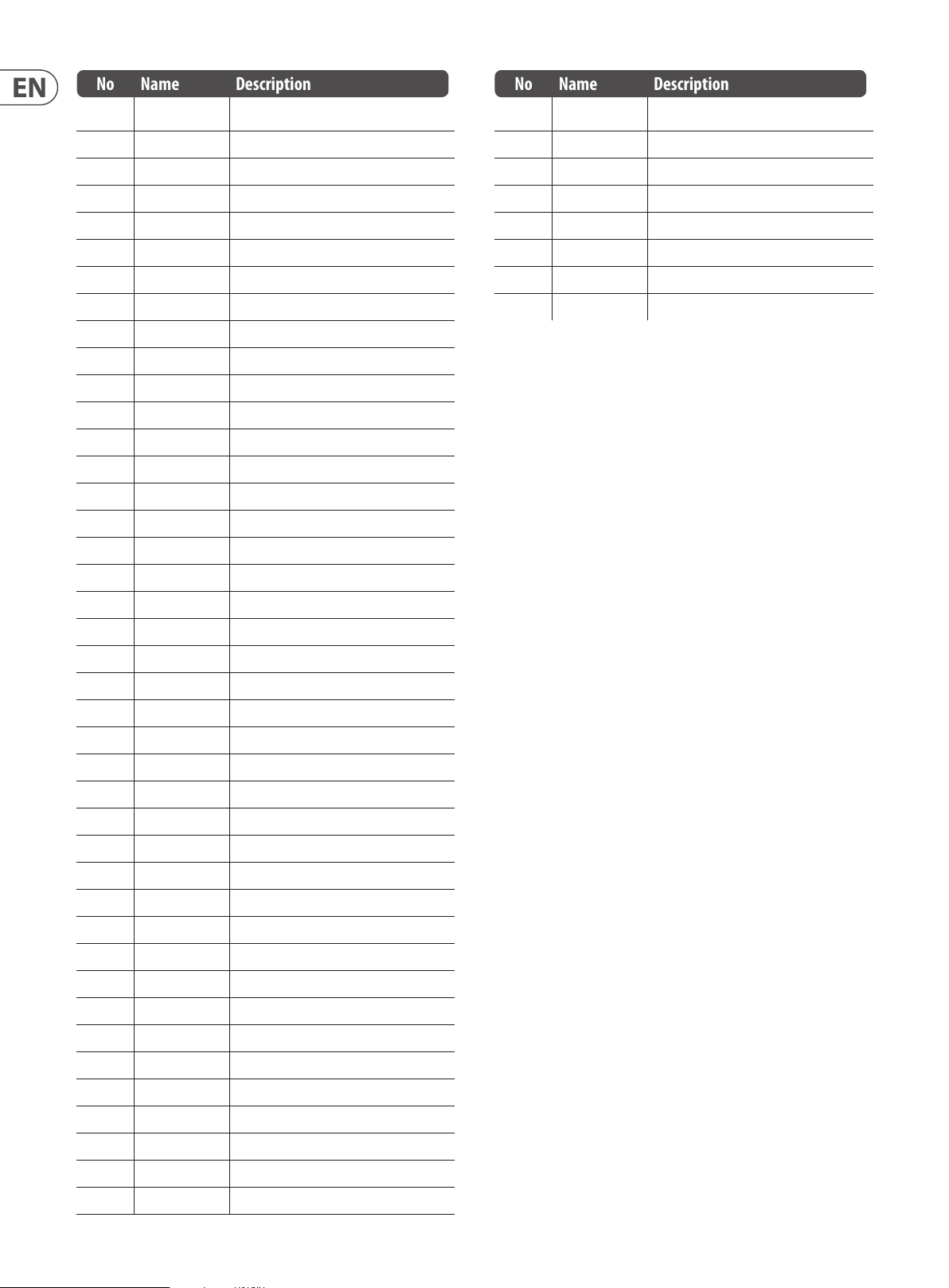
90 DeepMind 12D User Manual
No Name Description
40 Env1 DcyCur Envelope 1 Decay Time Curve
41 Env1 SuSCur Envelope 1 Sustain Level Curve
42 Env1 RelCur Envelope 1 Release Time Curve
43 Env2 Attack Envelope 2 Attack Time
44 Env2 Decay Envelope 2 Decay Time
45 Env2 Sus Envelope 2 Sustain Level
46 Env2 Rel Envelope 2 Release Time
47 Env2 AtCur Envelope 2 Attack Time Curve
48 Env2 DcyCur Envelope 2 Decay Time Curve
49 Env2 SuSCur Envelope 2 Sustain Level Curve
50 Env2 RelCur Envelope 2 Release Time Curve
51 Env3 Attack Envelope 3 Attack Time
52 Env3 Dec ay Envelope 3 Decay Time
53 Env3 Sus Envelope 3 Sustain Level
54 Env3 Rel Envelope 3 Release Time
55 Env3 AtCur Envelope 3 Attack Time Curve
No Name Description
81-92 Fx 1 Params Eects Slot 1 Parameters
93-10 4 Fx 2 Params Eects Slot 2 Parameters
105-116 Fx 3 Params Eects Slot 3 Parameters
117-12 8 Fx 4 Params Eects Slot 4 Parameters
129 Fx 1 Level Eects Slot 1 Level
130 Fx 2 Level Eects Slot 2 Level
131 Fx 3 Level Eects Slot 3 Level
132 Fx 4 Level Eects Slot 4 Level
Note: Destinations marked with a '*' are common to all voices.
** VCA Active - This destination aects the VCA Gain for all active voices.
*** VCA All - This destination aects the VCA Gain for all voices, regardless of
whether they are active or not.
56 Env3 DcyCur Envelope 3 Decay Time Curve
57 Env3 SuSCur Envelope 3 Sustain Level Curve
58 Env3 RelCur Envelope 3 Release Time Curve
59 VCA All** VCA Gain for All Voices
60 VCA Active** VCA Gain for Active Voices
61 VCA EnvDep VCA Envelope Depth
62 Pan Spread Pan Spread
63 VC A Pan VCA Pan
64* OSC2 Lvl OSC 2 Level
65* Noise Lvl Noise Level
66* HP Freq HPF Cut-o Frequency
67* Uni Detune Unison Detune
68* OSC Drift OSC Drift
69* Param Drift Parameter Drift
70* Drift Rate Drift Rate
71* Arp Gate Arpeggiator Gate
72* Seq Slew Control Sequencer Slew
73 Mod 1 Dep Mod Matrix Routing 1 Depth
74 Mod 2 Dep Mod Matrix Routing 2 Depth
75 Mod 3 Dep Mod Matrix Routing 3 Depth
76 Mod 4 Dep Mod Matrix Routing 4 Depth
77 Mod 5 Dep Mod Matrix Routing 5 Depth
78 Mod 6 Dep Mod Matrix Routing 6 Depth
79 Mod 7 Dep Mod Matrix Routing 7 Depth
80 Mod 8 Dep Mod Matrix Routing 8 Depth
Page 91

91 DeepMind 12D User Manual
9. Eects Reference Guide
9.1 Eects Table
No Name Description Device Inspiration Type
1 TC-DeepVRB TC Deep Reverb TC Hall of Fame* Reverb
2 AmbVerb Ambient Reverb Lexicon 480L Reverb
3 RoomRev Room Reverb Lexicon 480L Reverb
4 VintageRev Vintage Room Reverb EMT250 Reverb
5 HallRev Hall Reverb Lexicon 480L Reverb
6 ChamberRev Chamber Reverb Lexicon 480L Reverb
7 PlateRev Plate Reverb Lexicon PCM-70 Reverb
8 RichPltRev Rich Plate Reverb Lexicon 480L Reverb
9 GatedRev Gated Reverb Lexicon 300/480L Reverb
10 Reverse Reverse Reverb Lexicon 300/480L Reverb
11 ChorusVerb Chorus & Reverb Lexicon PCM-70 Reverb
12 Delay Verb Delay & Reverb Lexicon PCM-70 Reverb
13 FlangVerb Flange & Reverb Lexicon PCM-70 Reverb
14 MidasEQ Midas Equaliser Midas ProX* Processing
15 Enhancer Enhancer SPL Vitalizer Processing
16 FairComp Fair Compressor Fairchild 670 Processing
17 MulBndDist Multi-Band Distortion Midas ProX* Processing
18 RackAmp Rack Amplier Tech 21 SansAmp Processing
19 EdisonEX1 Stereo Imaging Edison EX-1 Processing
20 Auto Pan Auto-Panning Behringer X32* Processing
21 NoiseGate Noise Gate Midas ProX* Processing
22
Delay Delay Behringer X32* Delay
23 3TapDelay 3-Tap Delay Behringer X32* Delay
24 4TapDelay 4-Ta p Delay Behringer X32* Delay
25 T-RayDelay Tel-Ray Delay Tel-Ray Delay Delay
26 DecimDelay Decimator Delay Decimator Delay Delay
27 ModDlyRev Mod, Delay & Reverb Lexicon PCM-70 Delay
28 Chorus Chorus Behringer X32* Creative
29 Chorus-D Chorus D Roland Dimension D Creative
30 Flanger Flanger Behringer X32* Creative
31 Phaser Phase Behringer X32* Creative
32 MoodFilter Mood Filter Moog Type Filter Creative
33 DualPitch Dual Pitch Shifter Eventide Creative
34 Vintage Pitch Dual Pitch Shifter Eventide Creative
35 RotarySpkr Rotary Speaker Leslie Creative
* - Direct algorithms from the hardware devices designed by
Music Group companies.
9.2 Eects Descriptions
Here is a list and brief description of the eects available on the
DeepMind 12D synthesizer.
TC Deep Reverb
TC Electronic is synonymous with some of the best sounding reverbs out there.
There are nine iconic reverb modes you know and love into this eect that simply
sounds so insanely good – you just have to try it. It’s amazing that just four
controls (Mod, Decay, Tone and PreDelay) can give such a wide range of tonal
options – bright and springy, warm and bouncy or gigantic dark reections…
It’s all there – and then some.
The PRE DELAY knob controls the amount of time before the reverb is heard
following the source signal. TONE enhances high frequencies for positive settings
and enhances low frequencies for negative settings. DECAY controls the amount
of time it takes for the reverb to dissipate. Note: The decay range changes
depending which of the modes is selected.
HallRev, AmbVerb, RichPltRev, RoomRev, ChamberRev
These 5 reverb emulations are inspired by the Lexicon 480L. Hall simulates the
reverberation that occurs when sound is recorded in medium to large-sized
concert halls. Ambience creates a customizable virtual acoustic space to add
warmth and depth without coloring the direct sound.
The PRE DELAY fader controls the amount of time before the reverb is heard
following the source signal. DECAY controls the amount of time it takes for the
reverb to dissipate. SIZE controls the perceived size of the space being created by
the reverb. The DAMP fader adjusts the decay of the high frequencies within the
reverb tail. DIFF(usion) controls the initial reection density, and MIX controls the
eect output.
LO and HI CUT allow the frequencies aected by the reverb to be narrowed.
BASSMULT(iplier) controls the low frequency build-up. SPREAD emphasizes
the stereo eec t of the reverb. SHAPE adjusts the contour of the reverberation
envelope. MOD SPEED (AmbVerb) controls the reverb tail modulation rate and
TAIL GAIN (AmbVerb) adjusts the volume of the reverb tail. The Rich Plate and
Room reverbs allow the stereo ECHO DELAY and the delay FEEDBACK to be
adjusted independently for each side. The Chamber reverb allows the stereo
REFL(ection) DELAY and GAINtobe adjusted independently.
Page 92

92 DeepMind 12D User Manual
VintageRev
Vintage Room simulates the reverberation that occurs when sound is recorded in
a small room. When you want to add a bit of warmth and just a touch of reverb,
the Vintage Room breathes life into close-mic'd guitar and drum tracks. (Inspired
by the Quantec QRS)
Set the early reection times for the left and right channel with ER DELAY L
and ER DELAY R. ER LEVEL sets the loudness of the early reection level. REV
DELAY controls the amount of time before the reverberation is heard following
the source signal. HI/LOW MULTIPLY adjusts the decay time of the high and
bass frequencies. ROOM SIZE adjusts the size of the room eect being created
incrementally from small to large. HIGH CUT sets the frequency above which
the source signal does not pass through the reverb. DENSITY manipulates the
reection density in the simulated room. (This slightly changes the reverb decay
time). LOW CUT sets the frequency below which the source signal does not pass
through the reverb.
Plate Reverb
Gated Reverb
This eect was originally achieved by combining a reverb with a noise gate.
Ourgated reverb creates the same impression by a special shaping of the
reverbtail.
Gated Reverb is especially eective for creating a 1980s-style snare sound or to
enlarge the presence of a kick drum. (Inspired by the Lexicon 300/480L.)
PRE DELAY controls the amount of time before the reverberation is heard
following the source signal. DECAY controls the amount of time it takes for the
reverb to dissipate. ATTACK controls how fast the reection density builds up.
DENSITY shapes the reverb decay tail. The higher the density, the greater the
number of sound reections. SPREAD controls how the reection is distributed
through the envelope of the reverb. The LO CUT knob sets the frequency beneath
which the source signal will not pass through the reverb. The HiSvFr/ HiSvGn
knobs adjust a Hi-Shelving lter at the input of the reverb eect. DIFF(USION)
controls the initial reection density.
Reverse Reverb
A plate reverb was originally created by sending a signal through a transducer
to create vibrations on a plate of sheet metal which were then picked up as an
audio signal. Our algorithm simulates that sound with high initial diusion and a
bright colored sound. The Plate Reverb will give your tracks the sound heard on
countless hit records since the late 1950s. (Inspired by the Lexicon PCM-70.)
PRE DELAY controls the amount of time before the reverberation is heard
following the source signal. DECAY controls the amount of time it takes for the
reverb to dissipate. SIZE adjusts the size of the virtual room created by the reverb
eect. The DAMP knob adjusts the decay of high frequencies within the reverb
tail. DIFF(USION) controls the initial reection density. The LO CUT knob sets the
frequency beneath which the source signal will not pass through the reverb.
The HI CUT knob sets the frequency above which the source signal will not pass
through the reverb. The BASS MULT(IPLIER) knob adjusts the decay time of the
bass frequencies. XOVER controls the crossover point for bass. MOD DEPTH and
SPEED control the intensity and speed of the reverb tail modulation.
Reverse Reverb takes the trail of a reverb, turns it around, and places it in front
of the sound source. Use the swelling crescendo of the Reverse Reverb to add an
ethereal quality to vocal and snare tracks. (Inspired by the Lexicon 300/480L.)
Adjusting the PRE DELAY knob adds up to 200 milliseconds of time before the
reverb follows the source signal. The DECAY knob adjusts the time it takes for
the reverb to completely dissipate. RISE controls how quickly the eect builds
up. DIFF(USION) controls the initial reection density. SPREAD controls how the
reection is distributed through the envelope of the reverb. The LO CUT knob
sets a low frequency beneath which the source signal will not pass through the
reverb. The HiSvFr/HiSvGn knobs adjust a Hi-Shelving lter at the input of the
reverb eect.
Chorus + Chamber
Taking up only one FX slot, the Chorus + Chamber eect combines the shimmer
and doubling characteristics of a studio-grade Chorus with the sweet sound of a
traditional Chamber reverb. (Reverb is inspired by the Lexicon PCM 70.)
The BALANCE knob adjusts the balance between chorus and reverb.
Lowfrequencies can be excluded with the LO CUT knob, and the MIX knob adjusts
how much of the eect is added to the signal. SPEED, DELAY and DEPTH adjust
the rate, delay, and modulation depth of the chorus. The LFO PHASE between left
and right channel can be oset by up to 180 degrees, and WAVE adjusts the LFO
waveform from a sine wave to triangular wave. The PREDELAY knob determines
the hesitation before the reverb aects the signal. The DECAY knob adjusts how
quickly the reverb fades. The SIZE controls how large or small the simulated
space is (room, cathedral, etc.). The DAMPING knob determines the decay of high
frequencies within the reverb tail.
Page 93

93 DeepMind 12D User Manual
Delay + Chamber
Here we have combined Delay and Chamber reverb, so a single device can provide
a variety of delay settings, plus add just the right type and amount of reverb to
the selected signal. This device only uses one FX slot. (Inspired by the Lexicon
PCM 70.)
Use the BALANCE knob to adjust the ratio between delay and reverb.
Lowfrequencies can be excluded with the LO CUT knob, and the MIX adjusts
how much of the eect is added to the signal. The TIME knob adjusts the delay
time for the left channel delay, and the PATTERN sets the delay ratio for the
right channel delay. Adjust the FEEDBACK and trim some high frequencies with
the FEED HC (high-cut) knob. The XFEED knob allows you to send the delay
sound to the reverb eect, so instead of running completely parallel, the reverb
aects the echoes to a selected degree. The PREDELAY knob determines the
hesitation before the reverb aects the signal. The DECAY knob adjusts how
quickly the reverb fades. The SIZE controls how large or small the simulated
space is (room,cathedral, etc.). The DAMPING knob determines the decay of high
frequencies within the reverb tail.
Flanger + Chamber
Add the mind-bending, lter-sweeping eect of a state-of-the-art Flanger to the
elegant sweetening of a traditional Chamber reverb - all in one FX slot. (Inspired
by the Lexicon PCM 70.)
Enhancer
These Enhancers are so called “Psycho EQs”. They can enhance the signal
spectrum in bass, midrange and high frequencies but they dier from traditional
equalizers. When you need to generate maximum punch, clarity and detail,
without turning up the overall volume, our enhancers are the solution.
(Inspiredby the SPL Vitalizer.)
Adjust the BASS, MID and HI GAIN knobs to add or reduce content in those
spectrums. The BASS and HI Frequencies can be specically selected, while the
MID Q (bandwidth) can be adjusted instead. The OUT GAIN knob compensates for
changes in level resulting from the eect, and the SPREAD knob (Stereo version
only) emphasizes the stereo content for a wider mix. Engage the SOLO MODE
to isolate only the audio resulting from the eect so you can hear exactly what
you’re adding to the mix.
Fair Compressor
This model of a Fairchild 670 delivers some of the nest colorations in compressor
history. The two paths L/M and R/S both have the same functionality. The
controls include input GAIN, THRESHOLD, TIME and DC BIAS (which controls the
ratio and knee of the compression curve. There is also a BIAS BALANCE which can
help accentuate attacks. There are modes available for dual, stereo-linked, or
mid/side operation via the MOD control.
MulBndDist
The BALANCE knob adjusts the ratio between anger and reverb. Low frequencies
can be excluded with the LO CUT knob, and the MIX knob adjusts how much
of the eect is added to the signal. SPEED, DELAY and DEPTH adjust the rate,
delay,and modulation depth of the anger. FEEDback can be adjusted with
positive and negative amounts. The PHASE can be o set by up to 180 degrees.
The PREDELAY knob determines the hesitation before the reverb aects the
signal. The DECAY knob adjusts how quickly the reverb fades. The SIZE controls
how large or small the simulated space is (room, cathedral, etc.). The DAMPING
knob determines the decay of high frequencies within the reverb tail.
MidasEQ
The Midas EQ is a four-band sweep parametric equalizer taken from the Midas
Pro X console that allows tonal control of the input signal via the parametric EQ
section. The mid bands also have a Q Factor adjustment to tailor the shape of the
EQ curve. The four bands are low, low mid, high mid and high. Any combination
of the four bands can be used to control the signal.
The Multiband Distortion unit, useful for making sound gritty, adding more
warmth through saturation, or even enhancing a specic frequency region. There
are three bands, adjustable by a 24 dB per octave crossover lter.
There are six distortion types, going from soft saturation to more aggressive
distortion and post lter variants. The 'Drive' parameter controls the amount
of distortion introduced to the sound. This parameter, together with the right
distortion t ype, can instead bring some soft saturation to the sound.
The eect also features a Cabinet Unit applied to the output, which can add the
characteristic timbre of 11 dierent cabinet types.
Finally the level of the sound can be controlled by the input and output
gain parameters.
Page 94

94 DeepMind 12D User Manual
Rack Amplier
Modelled after the Tech 21 SansAmp, the Stereo / Dual Guitar Amp simulates the
sound of plugging into a real guitar amp. From shimmering cleans to saturated
crunch, the Stereo / Dual Guitar Amp allows an electric guitar player to sound
great without using an amp on stage. The PREAMP knob adjusts the amount of
input gain prior to the band-specic distortion adjustment. BUZZ adjusts the
low-end breakup, PUNCH adjusts the midrange distortion, and CRUNCH tailors
the high-frequency content and distortion for smooth or cutting notes. The DRIVE
knob simulates the amount of power amp distortion from a tube amp. The LOW
and HIGH knobs allow EQ adjustment independent of distortion content, and the
overall output is controlled by the LEVEL knob. There are 11 CABINET emulations
which can be selected using the CAB parameter. The CABINET simulation can also
be bypassed which allows the eect to func tion like a boost or distortion pedal.
Edison EX1
The EDISON EX1+ is a remarkably eective tool that allows manipulation of the
stereo eld. The eect oers stereo and mid/side input and output and a phase
correlation meter. Exaggerate the stereo eld with the ST SPREAD knob and
adjust the ratio of mono to stereo content with the BALANCE knob. The CENTER
DIST knob allows the mono content to be panned. Compensate for level changes
with the OUTPUT GAIN knob.
Delay
Stereo Delay provides independent control of left and right delay (echo) times
and features high and low pass lters for enhanced tone shaping of the delayed
signals. Use the Stereo Delay to give your mono signals a wide presence in the
stereo eld.
The MIX control lets you blend the source signal and the delayed signal.
TIMEadjusts the master delay time up to three seconds. LO CUT adjusts the low
frequency cut, allowing lower frequencies to remain unaected by the delay.
HI CUT adjusts the high frequency cut, allowing higher frequencies to remain
unaected by the delay. FACTOR L sets the delay on the left channel to rhythmic
fractions of the master delay time. FACTOR R sets the delay on the right channel
to rhythmic frac tions of the master delay time. OFFSET LR adds a delay dierence
between the lef t and right delayed signals. The FEED LO CUT/HI CUT adjusts lters
in the feedback paths. FEED L and FEED R control the amount of feedback for
the left and right channels. MODE sets the feedback mode: Mode ST sets normal
feedback for both channels, X crosses feedbacks between left and right channels.
M creates a mono mix within the feedback chain. P-P sets up a Ping-Pong delay.
(Note: the FEED R control is disabled in this mode.)
3-Tap Delay
Auto-Pan
Auto-pan creates an up and down volume change at a constant and even tempo
just like the guitar amps of yesteryear. Use the Auto-pan to add a unique “surfmusic” texture.
SPEED adjusts the LFO rate and DEPTH sets the amount of modulation. PHASE
can be used to set an LFO phase dierence between the left and right channel,
which can be used for panning eects. The WAVE knob blends the LFO waveform
between triangular and square shape. The signal envelope, shaped by ATTACK,
HOLD and RELEASE, can be used to modulate the LFO speed (ENV SPEED) and the
LFO modulation depth (ENV DEPTH).
NoiseGate
The Noise Gate not only handles the duties of a traditional version, but also oers
enhanced "Transient Accenting" characteristics to gated signals. Enhance the
attack envelope beyond merely opening the gate, and provide up to 12 dB of
additional transient energy to percussive programs. In many cases the DN265's
control over transients may prove to be a viable alternate to EQ.
Attack is exponential which means it can be set extremely fast to reduce signal
loss at the start of sounds while remaining sonically transparent - no clicks.
Gate release is reverse exponential so it can be set relatively fast and blend in
seamlessly with the natural decay of the material.
Sometimes called a 3-Tap Delay, the Triple Delay provides three delay stages with
independent frequency, gain, and pan controls. Create time-based echo eects
with the Triple Delay to increase the sense of stereo separation.
TIME sets the master delay time, which is also the delay time for the rst stage.
GAIN T sets the gain level of the rst stage of the delay. BASE T sets the position
of the rst delay stage in the stereo eld. X-FEEDindicates that stereo crossfeedback of the delays is active. FEEDBACK adjusts the amount of feedback.
FACTOR A controls the amount of delay time in the second stage of the delay.
GAIN A controls the gain level of the second delay stage. PAN A sets the position
of the second delay stage in the stereo eld. FACTOR B controls the amount
of delay time in the third stage of the delay. GAINB controls the gain level of
the third delay stage. PAN B sets the position of the third gain stage in the
stereo eld.
4-Tap Delay
The 4-Tap Delay provides 4 stages of delay with independently adjustable gain
and rate, allowing unique syncopation to be created in the layered repeats.
TIME sets the master delay time, which is also the delay time for the rst stage.
GAIN sets the gain for the rst stage. SPREAD positions the rst delay stage in
the stereo eld. A global FEEDBACK adjustment is also available. FACTOR A, B and
C adjust the delay rate relative to the global TIME setting for the 2nd, 3rd and
4th stages respectively. Each stage also has its own GAIN adjustment. X-FEED
indicates that stereo cross-feedback of the delays is active.
Page 95

95 DeepMind 12D User Manual
Tel-Ray Delay
Inspired by the original Tel-Ray hardware from the 1960's using a tuna can,
some oil and a motor. It has a very simple set of controls but allows you to create
delays, echo, chorus, vibrato and reverb type eects. An incredibly versatile and
creative eect which has a lush and unique character.
DELAY controls the delay time. SUSTAIN controls how long the delay is sustained
for. WOB controls the amount of wobble which is caused by age and quality of
materials in the original hardware.
Decimator Delay
This is a delay eect including a decimator unit in its chain. It will decimate the
sound by reducing the sampling frequency and the bit-depth. The Decimator
Delay is a creative tool that can be used in many ways, from emulating the
aliasing noise, found in older samplers, to generating complex, low- and rough
delay lines.
Decimate the sound by adjusting the DOWNSAMPLE and BIT-REDUCE. The lter
section will help you manipulate your preferred frequencies to smooth or retain
the grittiness of the sound. The TIME, FACTOR and FEEDBACK parameters will
handle the delay behavior. The DECIMATE (PRE-POST) parameter will set the
decimation to aect the input source or the only the delay line accordingly.
Chorus
Chorus samples the input, slightly detunes it and mixes it with the original
signal to produce a somewhat thicker, shimmering sound. Use it to thicken up
background vocals, or to double the sound of brass and woodwind instruments.
Where as DELAY L/R set the total amount of delay for the left and right channel,
WIDTH determines the amount of modulated delay. SPEED sets the modulation
speed. MIX adjusts the balance of the dry and wet signals. You can further sculpt
the sound by trimming some of the low and high end from the eected signal
with the LO and HI CUT knobs. Additionally, the PHASE knob can tweak the
phase oset of the LFO between left and right channel and the SPREAD knob
adjusts how much of the left channel is mixed into the right and vice versa.
Finally,theWAVE knob blends between the “Danish-style” digital triangular
chorus sound and the classic analog sine wave.
Dimensional Chorus
The Dimensional Chorus oers the most user-friendly and classic sounds,
bestdescribed as “space” and “dimensional”. The 4 MODE switches can
be engaged individually or simultaneously for light chorus or very thick,
exaggerated modulation.
Flanger
Modulation Delay + Reverb
Modulation Delay combines three of the most used time modulation eects
into one easy-to-operate unit, featuring true-stereo delay with a lush chorus,
toppedo with three reverb models to choose from.
The BALANCE knob adjusts ratio of delay to reverb. The processor chain can
operate as serial where one eect ows into the next, or parallel where each
eect is applied to the source signal independently. TIME, FEED(back), LOWand
HI CUT all aect the delay. Modulation DEPTH and SPEED are adjustable.
Threetypes of reverb are available – ambience, club and hall – with adjustable
DECAY and HI DAMP.
The Flanger emulates the phase-shifting sound (comb-ltering) originally
created by applying pressure against the ange of the reel on a tape recorder.
This eect creates a unique “wobbly” sound that is quite dramatic when used on
vocals and instruments.
The controls of this eect are nearly identical to the Chorus eect block.
Additionally, the FEEDBACK can be adjusted with positive and negative amounts
and also band-limited with the FEED HC (high-cut) and FEED LC (low-cut) knobs.
Page 96

96 DeepMind 12D User Manual
Phaser
A Stereo Phaser, or phase shifter, applies multiple STAGES of modulated lters to
the input signal to create a “notch” in the frequency response, and then applies
a MIX with the original for a “swirling” eect. Use the Stereo Phaser to add a
“spaced-out” sound to vocal or instrument tracks.
SPEED adjusts the LFO rate and DEPTH sets the LFO modulation depth. The BASE
knob adjusts the frequency range of the modulated lters. The resonance is
adjusted with the RES knob. The WAVE knob shapes the symmetry of the LFO
waveform and PHASE dials in an LFO phase dierence between the left and right
channel. The modulation source can also be the signal envelope, which produces
vowel-like opening and closing tones. The ENV knob adjusts how much this eect
takes place (positive and negative modulation is possible), and the ATTACK, HOLD
and RELEASE knobs all tailor the response of this feature.
Mood Filter
The Mood Filter uses an LFO generator and an auto-envelope generator to control
a VCF (voltage-controlled lter), as well as a side chain function where the
channel B signal controls the envelope of channel A.
This lter can be modulated with the signal’s envelope using the ENV MOD
(withpositive and negative amounts), ATTACK and RELEASE knobs, or the
LFOcan modulate the lter. The WAVE knob selects between 7 dierent wave
forms–triangular, sine, saw plus, saw minus, ramp, square, and random.
ThePHASE can be o set by up to 180 degrees. The SPEED knob adjusts the rate
of the LFOand the DEPTH adjusts the amount of LFO modulation. Adjustthe
resonance of the lter until self-oscillation with the RESO(nance) knob.
BASEadjusts the range of the lter from 20 Hz to 15 kHz. The MODE switch
selects between low pass (LP), high-pass (HP), band-pass (BP) and Notch. Use the
MIXknob to blend the eected signal with the dry sound. With the 4 POLE switch
engaged, there will be a steeper slope than the OFF (2 pole) setting. The DRIVE
knob adjusts the level and can also introduce an overdrive eect (as with real
analog lters) if pushed hard.
Stereo / Dual Pitch
a time dierence between the wet and dry sound. The LO and HI CUT knobs
allow the eected signal to be band-limited. The Dual Pitch eect allows
the leftandright channels to be adjusted independently, and allows GAIN
compensation andpanning of the two channels.
Note: If you notice any "glitching" that may occur when using low-level signals,
we recommend using the Vintage Pitch FX shown below.
Vintage Pitch
Pitch shifting is often used in two dierent ways. One is to set the Mix knob lower
and only use the Cent knob to make a small o set in pitch between the wet and
dry tones. This results in a “voice doubling” eec t that thickens the overall sound
in a more subtle way. The extreme use of the eect is to turn the Mix knob fully
clockwise so the entire signal is eected. This way, the signal can be shifted into
other keys up to an octave above or below the original. When used on a voice,
this results in a “chipmunk” sound or a low Darth Vader eect.
When the SEMI and CENT knobs are set at 12:00, the pitch is not altered.
Makingadjustments by semitone will have a very pronounced eect,
whereaschanges to the CENT knob will be very minor. The DELAY knob creates
a time dierence between the wet and dry sound. The LO and HI CUT knobs
allow the eected signal to be band-limited. The Dual Pitch eect allows the
leftandright channels to be adjusted independently, and allows FEEDBACK
andpanning of the two channels.
Rotary Speaker
Rotary Speaker emulates the sound of a Leslie rotating speaker. The Rotary
Speaker provides more exibility than its elec tromechanical counterpart, andcan
be used with a variety of instruments, and even vocals, to create a whirling,
psychedelic eect.
The LO SPEED and HI SPEED knobs adjust the rotational speed of the
SLOWand FAST Speed selection, and can be toggled with the FAST switch.
TheACCEL(eration) knob adjusts how quickly the speed increases and
decreases from the Slow mode to the Fast mode. The rotation eect can also
be disengaged with the STOP switch, which will stop the movement of the
speakers. DISTANCEadjusts the distance between the Rotary speakers and the
virtualmicrophone.
Pitch shifting is often used in two dierent ways. One is to set the Mix knob lower
and only use the Cent knob to make a small o set in pitch between the wet and
dry tones. This results in a “voice doubling” eec t that thickens the overall sound
in a more subtle way. The extreme use of the eect is to turn the Mix knob fully
clockwise so the entire signal is eected. This way, the signal can be shifted into
other keys up to an octave above or below the original. When used on a voice,
this results in a “chipmunk” sound or a low Darth Vader eect.
When the SEMI and CENT knobs are set at 12:00, the pitch is not altered.
Makingadjustments by semitone will have a very pronounced eect,
whereaschanges to the CENT knob will be very minor. The DELAY knob creates
Page 97

97 DeepMind 12D User Manual
9.3 Eects Parameters
Note: Eects parameters which appear as modulation destinations are marked with a '*'.
TC-DeepVRB (TC DEEP REVERB)
No DM12 REF PARAMETER UNITS MIN MAX DESCRIPTION
1 PST Preset — — — Options: Ambience, Church, Gate, Hall, Lo Fi, Modulated, Plate, Room, Spring, Tile, Default.
2* DCY Dec ay s 0.1 s 6.0 s Controls the amount of time it takes for the reverb to dissipate (range is preset dependant).
3* TON Tone % -50.0% 50.0% Enhances high frequencies/low frequencies for positive/negative settings respectivly.
4 PDY PreDelay ms 0.0 200.0 ms Controls the amount of time before the reverb is heard following the source signal.
5* MIX Mix % 0.0% 100% Controls the mix (or ratio) of wet (processed) and dry (unprocessed) signals.
* These parameters are available as modulation destinations in the Modulation Matrix
AmbVerb (AMBIENT REVERB)
No DM12 REF PARAMETER UNITS MIN MAX DESCRIPTION
1 PD PreDelay ms 0.0 200.0 ms Controls the amount of time bef ore the reverb is heard following the source signal.
2* DCY Dec ay s 0.2 s 7.3 s Controls the amount of time it takes for the reverb to dissipate.
3 SIZ Size — 2.0 100.0 Contro ls the perceived size of the space being created by the reverb.
4* DMP Damping Hz 1000 Hz 20000 Hz Adjust s the decay of the high frequencies within the reverb tail.
5 DIF Di usion — 1.0 30.0 Controls the initial reec tion density.
6* MIX Mix % 0.0% 100% Controls the mix (or ratio) of wet (processed) and dr y (unprocessed) signals.
7* LC LoCut Hz 10.0 Hz 50 0.0 Hz Allows the low f requencies aected by the reverb to be reduced.
8* HC Hi Cut Hz 200.0 Hz 20000.0 Hz Allows the high f requencies aected by the reverb to be re duced.
9 MOD Mod % 0.0% 100% Controls the reverb tail modulation depth.
10* TGN TailGain % 0.0 % 100% Adjusts the volume of the reverb tail.
* These parameters are available as modulation destinations in the Modulation Matrix
Page 98

98 DeepMind 12D User Manual
RoomRev (ROOM REVERB)
No DM12 REF PARAMETER UNITS MIN MAX DESCRIPTION
1 PRE PreDelay ms 0.0 200.0 ms Controls the amount of time before the reverb is heard following the source signal.
2* DCY Dec ay s 0.3 s 28.9 s Controls the amount of time it takes for the reverb to dissipate.
3 SIZ Size m 4.0 m 76.0 m Controls the perceived size of the space being created by the reverb.
4* DMP Damping Hz 1000 Hz 20000 Hz Adjust s the decay of the high frequencies within the reverb tail.
5 DIF Di usion % 0.0% 100% Controls the initial reection density.
6* MIX Mix % 0.0% 100% Controls the mix (or ratio) of wet (processed) and dr y (unprocessed) signals.
7* LC LoCut Hz 10.0 Hz 50 0.0 Hz Allows the low f requencies aected by the reverb to be reduced.
8* HC Hi Cut Hz 200.0 Hz 20000.0 Hz Allows the high f requencies aected by the reverb to be re duced.
9* LFX BassMult -- 0.2 4.0 Controls the low frequenc y build-up.
10 SPR Spread -- 0.0 50.0 Emphasizes the stereo eect of the reverb.
11* SHP Shape -- 0.0 2 50.0 Adjusts the contour of the reverberation envelope.
12 SPI Spin % 0.0% 100% Controls randomization / modulation eects within the reverb.
* These parameters are available as modulation destinations in the Modulation Matrix
VintageRev (VINTAGE ROOM REVERB)
No DM12 REF PARAMETER UNITS MIN MAX DESCRIPTION
1 PRE PreDelay ms 0.0 200.0 ms Controls the amount of time before the reverb is heard following the source signal.
2 SIZ Size % 1.0 % 100% Controls the perceived size of the space being created by the rever b. Aects DECAY range.
3* DCY Decay s 0.1 s 20.7 s Controls the amount of time it takes for the reverb to dissipate. Range dependant on SIZE.
4* LF X Lo Mult -- 0.1 10. 0 Controls the low f requency build-up.
5* HFX Hi Mult -- 0.1 10.0 Controls the high frequenc y build-up.
6* DEN Density % 0.0% 100 % Manipulates the reection density in the simulated room.
7* LC LoCut Hz 10.0 Hz 50 0.0 Hz Allows the low f requencies aected by the reverb to be reduced.
8* HC Hi Cut Hz 200.0 Hz 20000.0 Hz Allows the high frequencies aec ted by the reverb to be reduced.
9* ERL ER Level % 0.0 % 100 % S et the early reection times.
10 ERD ER Delay ms 0.0 200.0 ms Sets the loudness of the early ree ction level.
11* MIX Mix % 0.0% 100% Controls the mix (or ratio) of wet (processed) and dry (unpro cessed) signals.
12* FRZ Freeze -- OFF ON Applies freeze mode and blends signals into a continuous response.
* These parameters are available as modulation destinations in the Modulation Matrix
Page 99

99 DeepMind 12D User Manual
HallRev (HALL REVERB)
No DM12 REF PARAMETER UNITS MIN MAX DESCRIPTION
1 PD PreDelay ms 0.0 200.0 ms Controls the amount of time before the reverb is heard following the source signal.
2* DCY Dec ay s 0.2 s 4.9 s Controls the amount of time it takes for the reverb to dissipate.
3 SIZ Size -- 2.0 200.0 Controls the perceived size of the space being created by the reverb.
4* DMP Damping Hz 1000 Hz 20000 Hz Adjust s the decay of the high frequencies within the reverb tail.
5 DIF Di usion -- 1.0 30.0 Cont rols the initial reec tion density.
6* MIX Mix % 0.0% 100% Controls the mix (or ratio) of wet (processed) and dr y (unprocessed) signals.
7* LC LoCut Hz 10.0 Hz 50 0.0 Hz Allows the low f requencies aected by the reverb to be reduced.
8* HC Hi Cut Hz 200.0 Hz 20000.0 Hz Allows the high frequencies aec ted by the reverb to be reduced.
9* LFX BassMult -- 0.5 2.0 Controls the low frequenc y build-up.
10 SPR Spread -- 0.0 50.0 Emphasizes the stereo eect of the reverb.
11* SHP Shape -- 0.0 2 50.0 Adjusts the contour of the reverberation envelope.
12 MOD ModSpeed -- 0.0 100.0 Controls the reverb tail modulation rate.
* These parameters are available as modulation destinations in the Modulation Matrix
ChamberRev (CHAMBER REVERB)
No DM12 REF PARAMETER UNITS MIN MAX DESCRIPTION
1 PRE PreDelay ms 0.0 200.0 ms Controls the amount of time before the reverb is heard following the source signal.
2* DCY Dec ay s 0.3 s 28.9 s Controls the amount of time it takes for the reverb to dissipate.
3 SIZ Size m 4.0 m 76.0 m Controls the perceived size of the sp ace being created by the reverb.
4* DMP Damping Hz 1000 Hz 20000 Hz Adjust s the decay of the high frequencies within the reverb tail.
5 DIF Di usion % 0.0% 100% Controls the initial reection density.
6* MIX Mix % 0.0% 100% Controls the mix (or ratio) of wet (processed) and dr y (unprocessed) signals.
7* LC LoCut Hz 10.0 Hz 50 0.0 Hz Allows the low f requencies aected by the reverb to be reduced.
8* HC Hi Cut Hz 200.0 Hz 20000.0 Hz Allows the high frequencies aec ted by the reverb to be reduced.
9* LFX BassMult -- 0.2 4.0 Controls the low frequenc y build-up.
10 SPR Spread -- 0.0 50.0 Emphasizes the stereo eect of the reverb.
11* SHP Shape -- 0.0 2 50.0 Adjusts the contour of the reverberation envelope.
12 SPI Spin % 0.0% 100% Controls randomization / modulation eects within the reverb.
* These parameters are available as modulation destinations in the Modulation Matrix
Page 100

100 DeepMind 12D User Manual
PlateRev (PLATE REVERB)
No DM12 REF PARAMETER UNITS MIN MAX DESCRIPTION
1 PD PreDelay ms 0.0 200.0 ms Controls the amount of time before the reverb is heard following the source signal.
2* DCY Dec ay s 0.5 s 10.0 s Contro ls the amount of time it takes for the reverb to dissipate.
3 SIZ Size — 2.0 200.0 Controls the perceived size of the space being created by the reverb.
4* DMP Damping Hz 1000 Hz 20000 Hz Adjust s the decay of the high frequencies within the reverb tail.
5 DIF Di usion — 1.0 30.0 Controls the initial reec tion density.
6* MIX Mix % 0.0% 100% Controls the mix (or ratio) of wet (processed) and dr y (unprocessed) signals.
7* LC LoCut Hz 10.0 Hz 50 0.0 Hz Allows the low f requencies aected by the reverb to be reduced.
8* HC Hi Cut Hz 200.0 Hz 20000.0 Hz Allows the high frequencies aec ted by the reverb to be reduced.
9* LFX BassMult — 0.5 2.0 Controls the low frequency build-up.
10* XOV Xover Hz 10.0 Hz 500.0 Hz Controls the crossover point for bass multiplier.
11 MOD ModDepth — 1.0 50.0 Controls the reverb tail modulation depth.
12 MDS ModSpeed — 0.0 10 0.0 Controls the reverb tail modulation rate.
* These parameters are available as modulation destinations in the Modulation Matrix
RichPltRev (RICH PLATE REVERB)
No DM12 REF PARAMETER UNITS MIN MAX DESCRIPTION
1 PD PreDelay ms 0.0 200.0 ms Controls the amount of time before the reverb is heard following the source signal.
2* DCY Dec ay s 0.3 s 28.9 s Controls the amount of time it takes for the reverb to dissipate.
3 SIZ Size m 4.0 m 39.0 m Controls the perceived size of the sp ace being created by the reverb.
4* DMP Damping Hz 1000 Hz 20000 Hz Adjust s the decay of the high frequencies within the reverb tail.
5 DIF Di usion % 0.0% 100% Controls the initial reection density.
6* MIX Mix % 0.0% 100% Controls the mix (or ratio) of wet (processed) and dr y (unprocessed) signals.
7* LC LoCut Hz 10.0 Hz 50 0.0 Hz Allows the low f requencies aected by the reverb to be reduced.
8* HC Hi Cut Hz 200.0 Hz 20000.0 Hz Allows the high frequencies aec ted by the reverb to be reduced.
9* LFX BassMult — 0.2 4.0 Controls the low frequency build-up.
10 SPR Spread — 0.0 50.0 Emphasizes the stereo e ect of the reverb.
11* ATK Attack — 0.0 100. 0 Adjusts the contour of the reverb eration envelope.
12* SPN Spin % 0.0% 100 % Controls randomization / modulation eects within the reverb.
* These parameters are available as modulation destinations in the Modulation Matrix
 Loading...