


Quick Start Guide
CP3A-M MIXER
Legendary Analog Mixer/Utility Module
for Eurorack
(EN) Controls
(5)
(2)
(1)
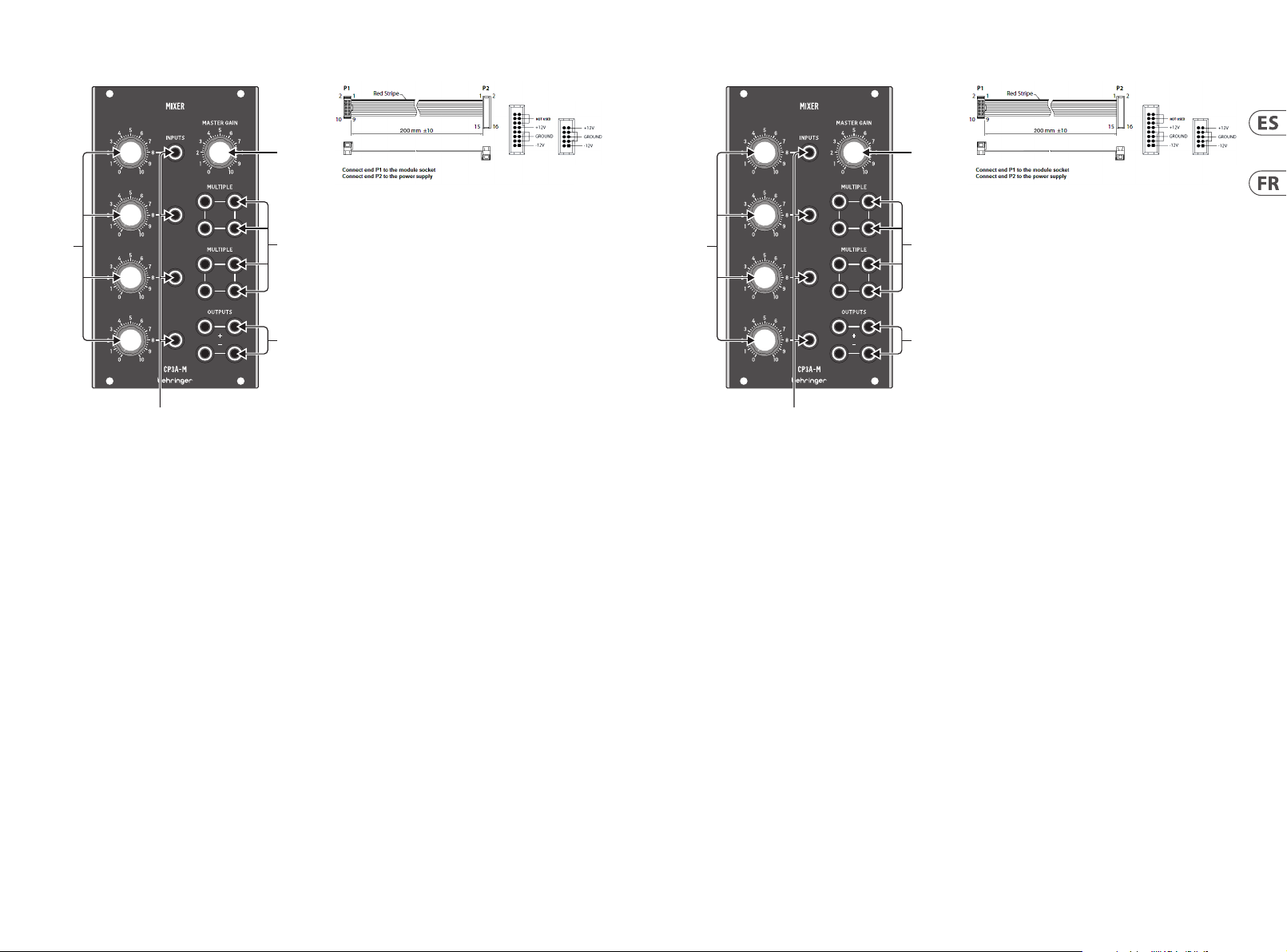
(1) CHANNEL INPUTS connect the incoming signals
via cable s with 3.5 mm TS connec tors.
(2 ) CHANNEL GAIN kn obs adjust the inpu t volume
for the CHAN NEL INPUTS.
(3 ) MULTIPLE connec tions act as a patc hbay so that copies
of the inpu t signals can be route d out to other module s
for further processing.
(4 ) OUTPUTS connectio ns send out the mixer module’s
nal, summed signal. The OUTPUTS section
feature s two sets of outp ut jacks with nega tive
and positive polarity.
(5 ) MAS TER GAIN controls the nal volume
at the OUTPUTS jacks.
(3)
(4)
Power Connection
The CP3A-M MIXER c omes with the requ ired power cable
for conne cting to a standar d Eurorack power sup ply system.
Follow the se steps to connec t power to the module. I t is easier
to make thes e connections b efore the module ha s been
mounted in to a rack case.
1. Turn the power su pply or rack case p ower o and
disconne ct the power cabl e.
2. Insert the 16- pin connector o n the power cable into t he
socket on t he power supply or rac k case. The connec tor has
a tab that wi ll align with the gap in t he socket, so it can not
be inser ted incorrec tly. If the power supply d oes not have
a keyed socke t, be sure to orient pi n 1 (-12 V) with the red
stripe o n the cable.
3. Insert the 10 -pin connecto r into the socket on th e back of
the modul e. The connector ha s a tab that will align wi th the
socket for correct orientation.
4. After both en ds of the power cable hav e been securely
attac hed, you may mount the mo dule in a case and tur n on
the power supply.
Installation
The neces sary screws ar e included with th e module for mount ing
in a Eurorac k case. Connect t he power cable bef ore mounting.
Dependi ng on the rack case, t here may be a series o f xed holes
spaced 2 HP ap art along the leng th of the case, or a tr ack
that allows individual threaded plates to slide along the length
of the cas e. The free-movi ng threaded plate s allow precise
positio ning of the module, bu t each plate should be p ositioned
in the approximate relation to the mounting holes in your module
before attaching the screws.
Hold the mo dule against the Eur orack rails so that e ach of the
mounting h oles are aligned wi th a threaded rail o r threaded
plate. Att ach the screws par t way to start, w hich will allow
small adjus tments to the pos itioning while you g et them all
aligned. Af ter the nal posi tion has been est ablished,
tighten the screws down.
V 1.0
3Quick Start Guide2 CP3A-M MIXER
(ES) Controles
(5)
(2)
(3)
(4)
(1)
(1) ENTRADAS DE C ANAL conectan la s señales entrante s
mediante c ables con conec tores TS de 3,5 mm.
(2 ) Las p erillas CHANNEL GAIN ajust an el volumen de entra da
para CHANNE L INPUTS.
(3 ) Las conexiones MÚLTIPLES act úan como un patchbay
para que las c opias de las señales d e entrada se puedan
enrutar a o tros módulos par a su posterior pro cesamiento.
(4 ) Las conexiones OUTPUTS enví an la señal sumada nal
del módul o mezclador. La secci ón de SALIDAS present a
dos juego s de tomas de salida con p olaridad negati va y
positiva.
(5 ) MAS TER GAIN controla el vol umen nal en los
jacks OUTPUTS.
Conexión Eléctrica
El CP3A-M MIXER vi ene con el cable de ali mentación neces ario
para cone ctarse a un sis tema de alimentaci ón estándar Euror ack.
Siga esto s pasos para conec tar la energía al mó dulo. Es más fácil
realizar e stas conexio nes antes de que el módu lo se haya montado
en una caja de r ack.
1. Apague la f uente de alimentac ión o la caja del bast idor y
descone cte el cable de ali mentación.
2. Inserte el con ector de 16 pines del c able de alimentac ión
en la toma de la f uente de alimentac ión o en la caja del
bastid or. El conector tiene u na pestaña que se al ineará
con el espac io en el zócalo, por lo qu e no se puede inser tar
incorrectamente. Si la fuente de alimentación no tiene un
enchufe c on llave, asegúrese d e orientar el pin 1 (-12 V) con
la raya roja de l cable.
3. Inserte el co nector de 10 pines en e l zócalo en la part e
poster ior del módulo. El cone ctor tiene una pe staña que se
alineará co n el enchufe para un a orientación cor recta.
4. Una vez que ambos e xtremos del ca ble de alimentació n se
hayan conectado rmemente, puede montar el módulo en
una caja y enc ender la fuente de alim entación.
Instalación
Los tornil los necesarios s e incluyen con el mód ulo para su montaje
en una caja Eu rorack. Conec te el cable de aliment ación antes
del montaje.
Dependi endo de la caja del bas tidor, puede haber una s erie de
orici os jos separados 2 H P a lo largo de la caja, o una pi sta que
permit a que las placas rosc adas individual es se deslicen a lo larg o
de la caja. L as placas roscad as de movimiento libr e permiten
un posici onamiento precis o del módulo, pero ca da placa debe
colocar se en una relación ap roximada con los or icios de montaje
en su módulo antes de colocar los tornillos.
Sosteng a el módulo contra lo s rieles Eurorac k de modo que cada
uno de los or icios de montaje q ueden alineados co n un riel o
placa roscada. Coloque los tornillos parcialmente para comenzar,
lo que perm itirá pequeños aj ustes en la posici ón mientras los
alinea. Una vez establecida la posición nal, apriete los tornillos.
(FR) Réglages
(5)
(2)
(3)
(4)
(1)
(1) Les ENTRÉES DE CA NAL connectent les signaux entrants
via des câb les avec connect eurs TS 3,5 mm.
(2 ) Les b outons CHANNEL GAIN rè glent le volume d’entrée
pour les CHA NNEL INPUTS.
(3 ) Les b outons CHANNEL GAIN règlent le vo lume d’entrée
pour les CHA NNEL INPUTS.
(4 ) PLUSIEUR S connexions agissent comme un patchbay
an que des co pies des signaux d’entrée puisse nt
être acheminées vers d’autres modules pour un
traitement ultérieur.
(5 ) Les co nnexions OUTPUTS envoient le signal nal
additionné du module de mixage. La section OUTPUTS
comprend d eux jeux de prise s de sortie avec une p olarité
négative et positive.
(6 ) MAS TER GAIN contrôle le vol ume nal aux
prises OUTPUTS.
Connexion Électrique
Le CP3A-M MIXER es t livré avec le câbl e d’alimentation req uis
pour la conn exion à un systèm e d’alimentation Euro rack standard.
Suivez ces é tapes pour conne cter l’alimentat ion au module. Il est
plus faci le d’eectuer ces co nnexions avant que l e module n’ait été
monté dans un b oîtier en rack.
1. Mette z le bloc d’alimentati on ou le boîtier de rac k hors
tension et débranchez le câble d’alimentation.
2. Insérez le conn ecteur à 16 broches d u câble d’alimentati on
dans la pris e du bloc d’alimentati on ou du boîtier du ra ck.
Le connec teur a une languet te qui s’alignera avec l’espa ce
dans la pris e, il ne peut donc pas êt re inséré de manière
incorre cte. Si le bloc d’alimen tation n’a pas de prise à c lé,
assurez- vous d’orienter la broc he 1 (-12 V) avec la bande
rouge sur le c âble.
3. Insérez le con necteur à 10 broche s dans la prise à l’arriè re
du module. Le c onnecteur a une lan guette qui s’aligne ra
avec la pris e pour une orientat ion correcte.
4. Une fois que les de ux extrémité s du câble d’alimentat ion
ont été soli dement xées, vous p ouvez monter le mod ule
dans un boîtier et allumer l’alimentation.
Installation
Les vis néc essaires sont in cluses avec le modul e pour le montage
dans un boî tier Eurorack. Con nectez le câbl e d’alimentation avant
le montage.
Selon le ca s de rack, il peut y avoi r une série de trous xes espacés
de 2 HP sur la long ueur du cas, ou une pis te qui permet aux
plaques l etées individu elles de glisser le lo ng de la longueur
du cas. Les p laques letées à dé placement libre pe rmettent un
positionnement précis du module, mais chaque plaque doit être
positionnée approximativement par rapport aux trous de montage
de votre mo dule avant de xer les vi s.
Maintene z le module contre les r ails Eurorack de so rte que
chacun de s trous de montage s oit aligné avec un rail leté ou une
plaque le tée. Fixez les vis par tiellement po ur commencer, ce qui
permettra de petits ajustements au positionnement pendant
que vous les a lignerez tous. Une f ois la position nal e établie,
serrez l es vis.

4 5Quick Start GuideCP3A-M MIXER
(DE) Bedienelemente
(5)
(2)
(3)
(4)
(1)
(1) KANAL-EINGÄNGE verbinden die eingehenden Signale
über Kabel mit 3,5-mm-TS-Steckern.
(2 ) Die CHANNEL GAIN-Regler stellen die Eingangslautstärke
für die CHAN NEL INPUTS ein.
(3 ) MEHRERE Verbindungen dienen als Patchbay, so dass
Kopien der Eingangssignale zur weiteren Verarbeitung an
andere Module weitergeleitet werden können.
(4 ) OUTPUTS-Verbindungen senden das endgültige
summierte Signal des Mischermoduls aus. Der Abschnitt
OUTPUTS enthält zwei Sätze von Ausgangsbuchsen mit
negativer und positiver Polarität.
(5 ) MAS TER GAIN regelt die End lautstärke an de n
OUTPUTS-Buchsen.
Netzanschluss
Der CP3A-M MIXER w ird mit dem erfo rderlichen Stro mkabel für
den Anschluss an ein Standard-Eurorack-Stromversorgungssystem
geliefe rt. Befolgen S ie diese Schrit te, um das Modul mit Stro m
zu versorgen. Es ist einfacher, diese Verbindungen herzustellen,
bevor das Modul in einem Rackgehäuse montiert wurde.
1. Schalten S ie das Netzteil o der das Rackgehäus e aus und
ziehen Sie da s Netzkabel ab.
2. Stecken Sie den 16-p oligen Stecker am Net zkabel in die
Buchse am N etzteil oder im R ack-Gehäuse. Der A nschluss
verfü gt über eine Lasc he, die an der Lücke in der Bu chse
ausgerichtet ist, sodass sie nicht falsch eingesetzt werden
kann. Wenn das N etzteil keine Sc hlüsselbuchse h at, richten
Sie Pin 1 (-12 V) mit dem roten Stre ifen am Kabel aus.
3. Stecken Sie den 10- poligen Stecker in di e Buchse auf der
Rücks eite des Moduls. Der A nschluss verf ügt über eine
Lasche, d ie zur korrekten Au srichtung an der Bu chse
ausgerichtet wird.
4. Nachdem beide E nden des Netzkab els fest angesc hlossen
wurden, können Sie das Modul in einem Gehäuse
montieren und die Stromversorgung einschalten.
Installation
Die erforderlichen Schrauben sind im Lieferumfang des Moduls für
die Montage in einem Eurorack-Gehäuse enthalten. Schließen Sie
das Netzkabel vor der Montage an.
Abhängig vo m Rack-Gehäuse ka nn es eine Reihe von fes ten
Löchern g eben, die entlang der L änge des Gehäuse s 2 PS
voneinander entfernt sind, oder eine Schiene, mit der einzelne
Gewindeplatten entlang der Länge des Gehäuses gleiten
können. Die frei beweglichen Gewindeplatten ermöglichen eine
präzise Positionierung des Moduls. Jede Platte sollte jedoch in
ungefährem Verhältnis zu den Befestigungslöchern in Ihrem
Modul positioniert werden, bevor Sie die Schrauben anbringen.
Halten Sie das Modul so gegen die Eurorack-Schienen, dass
jedes der Befestigungslöcher mit einer Gewindeschiene oder
einer Gewindeplatte ausgerichtet ist. Bringen Sie die Schrauben
teilweise an, um zu beginnen. Dadurch können Sie die Position
geringfügig anpassen, während Sie alle ausrichten. Ziehen Sie
die Schrauben fest, nachdem die endgültige Position
festgelegt wurde.
(PT) Controles
(5)
(2)
(3)
(4)
(1)
(1) CHANNEL INPUTS conecta o s sinais de entrada po r meio
de cabos co m conectores TS d e 3,5 mm.
(2 ) Os bo tões CHANNEL GAIN ajustam o vol ume de entrada
para CHANNEL INPUTS.
(3 ) Conexõ es MÚLTIPLAS agem co mo um patchbay para qu e
as cópias do s sinais de entrada po ssam ser roteadas p ara
outros módulos para processamento posterior.
(4 ) As co nexões OUTPUTS enviam o sinal nal somado do
módulo mixer. A seção OUTPUTS apresenta dois conjuntos
de conec tores de saída com p olaridade negati va e positiva.
(5 ) MAS TER GAIN controla o volu me nal nos
conectores OUTPUTS.
Conexão de Força
O CP3A-M MIXER vem co m o cabo de alimentaç ão necessário p ara
conexão a u m sistema de fonte de ali mentação Euror ack padrão.
Siga est as etapas para con ectar a aliment ação ao módulo. É mais
fácil fa zer essas conexõ es antes que o módulo s eja montado em
um gabinet e de rack.
1. Desligue a f onte de alimentaç ão ou o gabinete do rac k e
descone cte o cabo de alime ntação.
2. Insira o conec tor de 16 pinos do cabo de al imentação no
soquete d a fonte de alimentaç ão ou no gabinete do ra ck. O
conec tor possui uma aba que s e alinhará com a lacuna n o
soquete, p ortanto, não pode s er inserido inco rretamente.
Se a fonte de al imentação não ti ver um soquete chavead o,
certi que-se de orien tar o pino 1 (-12 V) com a fai xa
vermelha n o cabo.
3. Insira o conec tor de 10 pinos no soqu ete na parte tras eira
do módulo. O co nector possui u ma guia que se alinha ao
soquete para orientação correta.
4. Depois que as dua s extremidade s do cabo de aliment ação
estiverem rmemente conectadas, você pode montar o
módulo em um g abinete e ligar a fonte d e alimentação.
Instalação
Os paraf usos necessár ios estão incluí dos com o módulo para
montage m em uma caixa Eurora ck. Conecte o ca bo de alimentaçã o
antes da montagem.
Depende ndo da caixa do rack , pode haver uma série d e orifícios
xos espa çados de 2 HP ao longo do co mprimento da cai xa, ou
uma trilha q ue permite que plac as roscadas indi viduais deslizem
ao longo do co mprimento da caix a. As placas rosc adas de
moviment o livre permitem o po sicionamento pre ciso do módulo,
mas cada pla ca deve ser posici onada em uma relação ap roximada
com os orif ícios de montag em em seu módulo antes d e prender
os parafusos.
Segure o mó dulo contra os tri lhos Eurorack de mo do que cada um
dos orif ícios de montage m estejam alinhados c om um trilho ou
placa rosqueada. Prenda os parafusos parcialmente para começar,
o que permitirá pequenos ajustes no posicionamento enquanto
você os alinh a. Após a posição na l ter sido estabele cida, aperte
os parafusos.
6 7Quick Start GuideCP3A-M MIXER
(IT) Controlli
(5)
(2)
(3)
(4)
(1)
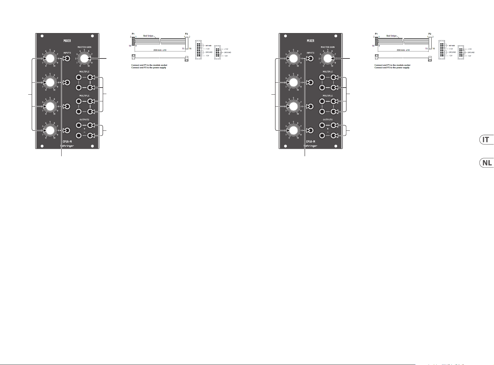
(1) INGRESSI DI C ANALE collegano i segna li in ingresso
tramite c avi con connetto ri TS da 3,5 mm.
(2 ) Le man opole CHANNEL GAIN regolano il v olume di
ingress o per gli INGRESSI DI CA NALE.
(3 ) Le conn essioni MULTIPLE fungono da pa tchbay in
modo che le c opie dei segnali di in gresso possan o essere
indirizzate ad altri moduli per ulteriori elaborazioni.
(4 ) Le connessioni OUTPUTS OUTPUTS inviano il segnale
nale e sommato del modulo mixer. La sezione OUTPUTS
dispone di d ue set di jack di usci ta con polarità ne gativa
e positiva.
(5 ) MAS TER GAIN controlla il vol ume nale alle
prese OUTPUTS.
Connessione di Alimentazione
Il CP3A-M MIXER vi ene fornito con il c avo di alimentazion e
necessario per il collegamento a un sistema di alimentazione
Eurorac k standard. Segu ire questi pass aggi per collegare
l’alimenta zione al modulo. È più f acile eettu are questi
collegam enti prima che il mod ulo sia stato monta to in un
case rack.
1. Spegner e l’alimentatore o il ca se del rack e scolleg are il
cavo di alimentazione.
2. Inserire il con nettore a 16 pin del cavo d i alimentazione
nella pres a sull’alimentator e o sul case del rack. I l
connettore ha una linguetta che si allineerà con lo spazio
nella pres a, quindi non può ess ere inserito in mo do errato.
Se l’aliment atore non dispone di u na presa con chiave,
assicur arsi di orientar e il pin 1 (-12 V) con la stris cia rossa
sul cavo.
3. Inserire il co nnettore a 10 pin nella p resa sul retro de l
modulo. Il co nnettore ha una lin guetta che si alli neerà con
la presa p er il corretto or ientamento.
4. Dopo che entra mbe le estremit à del cavo di alimenta zione
sono sta te ssate saldamen te, è possibile mont are il
modulo in un a custodia e accend ere l’alimentatore.
Installazione
Le viti nec essarie sono in cluse con il modulo p er il montaggio in
una custo dia Eurorack. Co llegare il cavo di alim entazione pri ma
del montaggio.
A seconda d el case del rack , potrebbero es serci una serie di f ori
ssi dist anziati di 2 HP l’uno dall ’altro lungo la lunghe zza del case,
o un binario c he consente alle sin gole piastre le ttate di scor rere
lungo la lung hezza del cas e. Le piastre let tate a movimento li bero
consentono un posizionamento preciso del modulo, ma ciascuna
piastra deve essere posizionata in relazione approssimativa con
i fori di mo ntaggio nel modu lo prima di ssare l e viti.
Tenere il modul o contro le guide Euro rack in modo che ci ascuno dei
fori di mo ntaggio sia allinea to con una guida let tata o una piast ra
lett ata. Attaccar e le viti in parte p er iniziare, il che con sentirà
piccole regolazioni al posizionamento mentre le si allineano tutte.
Dopo aver st abilito la posizi one nale, serrar e le viti.
(NL) Bediening
(5)
(2)
(3)
(4)
(1)
(1) KANAALINGANG EN verbinden de inkomende signalen via
kabels me t 3,5 mm TS-connec toren.
(2 ) CHANNEL GAIN- knoppen regelen het ingangsvolume
voor de CHANNE L INPUTS.
(3 ) MEERDERE verbindingen werken als een patchbay,
zodat kopieën van de ingangssignalen naar andere
modules kunnen worden geleid voor verdere verwerking.
(4 ) OUTPUTS-verbindingen sturen het laatste,
opgetelde signaal van de mixermodule. De OUTPUTSsecti e heeft twee s ets uitgangsjac ks met negatieve
en positieve polariteit.
(5 ) MAS TER GAIN regelt het uiteindelijke volume bij de
OUTPUTS-aansluitingen.
Power Connection
De CP3A-M MIXER wo rdt geleverd met de b enodigde
voedingskabel voor aansluiting op een standaard Eurorackvoedings systeem. Volg deze s tappen om de modu le van stroom
te voorzi en. Het is gemakkelij ker om deze aansluitin gen te maken
voordat de module in een rekbehuizing is gemonteerd.
1. Schakel de vo eding of de rekbe huizing uit en koppe l de
voedingskabel los.
2. Steek de 16-pins co nnector van de voe dingskabel in de
aansluiting op de voedingseenheid of rekbehuizing. De
connec tor heeft een li pje dat wordt uitgel ijnd met de
opening in d e socket, zodat dez e niet verkeerd kan wo rden
geplaat st. Als de voeding ge en contactdoo s met sleutel
heef t, zorg er dan voor dat pen 1 (-12 V) met de rod e streep
op de kabel wordt georiënteerd.
3. Steek de 10-pin s connector in de aan sluiting aan de
achterk ant van de module. De con nector heef t een lipje dat
uitgelij nd is met de aansluiti ng voor de juiste ori ëntatie.
4. Nadat beide uiteinden van de voedingskabel stevig zijn
bevesti gd, kunt u de module in e en hoesje monteren e n de
voeding inschakelen.
Installatie
De benodi gde schroeven wor den bij de module gele verd voor
montage i n een Eurorack-koe r. Sluit de voe dingskabel aan
voor montage.
Afhanke lijk van de rackbehu izing kan er een ree ks vaste gaten zijn
die 2 HP uit elk aar liggen over de leng te van de behuizing, o f een
rail waard oor individuele p laten met schroe fdraad langs de leng te
van de behuizing kunnen schuiven. De vrij bewegende plaatjes
met schroefdraad maken een nauwkeurige positionering van de
module mo gelijk, maar elke plaa t moet ongeveer in ver houding
tot de monta gegaten in uw modul e worden geplaats t voordat u
de schroeven bevestigt.
Houd de mod ule tegen de Eurorac k-rails zodat elk van de
montage gaten is uitgelijnd m et een rail met schr oefdraad of een
plaat met sc hroefdraad. B evestig de schro even halverwege o m
te beginnen, waardoor kleine aanpassingen aan de positionering
mogelijk z ijn terwijl u ze allem aal op één lijn krijg t. Draai de
schroev en vast nadat de deni tieve positie is be paald.

8 9Quick Start GuideCP3A-M MIXER
(SE) Kontroller
(5)
(2)
(3)
(4)
(1)
(1) KANALINGÅNGAR ansluter inkommande signaler via
kablar med 3,5 mm TS-kontakter.
(2 ) CHANNEL GAIN- knapparna justerar ingångsvolymen för
CHANNEL INPUTS.
(3 ) FLER A anslutningar f ungerar som en patc hbay så att
kopior av insignalerna kan dirigeras till andra moduler för
vidare bearbetning.
(4 ) OUTPUTS-anslutningar skick ar ut mixermodulens
slutliga, summerade signal. Avsnittet OUTPUTS har två
uppsättningar utgångar med negativ och posit iv polaritet.
(5 ) MAS TER GAIN kontrollerar slutvolymen vid
OUTPUTS-uttagen.
Strömanslutning
CP3A-M MIXER leve reras med den nödv ändiga strömka beln för
anslutni ng till ett vanlig t Eurorack-nätagg regat. Följ dess a steg
för att a nsluta ström til l modulen. Det är lät tare att göra de ssa
anslutningar innan modulen har monterats i ett rackfodral.
1. Stäng av str ömmen eller rackh öljet och koppla
bort strömkabeln.
2. Sätt i den 16-p oliga kontakten p å strömkabeln i ut taget på
nätaggr egatet eller rack fodralet. Kont aktdonet har en i k
som kommer i li nje med springan i ut taget så att d en inte
kan sät tas in felaktig t. Om strömför sörjningen int e har ett
nyckelut tag, se till att or ientera stif t 1 (-12 V) med den röda
remsan på k abeln.
3. Sätt i 10-po lig kontakt i ut taget på baksid an av modulen.
Kontakt donet har en ik som kom mer i linje med utt aget
för korrekt orientering.
4. När båda ändarna av s trömkabeln har a nslutits
ordentli gt kan du montera mod ulen i ett fodra l och
slå på strömförsörjningen.
Installation
De nödvän diga skruvarna i ngår i modulen för mo ntering i ett
Eurorack-fodral. Anslut strömkabeln före montering.
Beroend e på stativhölj et kan det nnas en ser ie fasta hål som
är åtskil da 2 hk längs höljets lä ngd eller ett spår s om gör att
enskilda gängade plattor kan glida längs höljets längd. De fritt
rörliga gängade plattorna möjliggör exakt positionering av
modulen, m en varje platta bö r placeras i ungef ärlig relation ti ll
monteringshålen i din modul innan skruvarna fästs.
Håll module n mot Eurorack-skeno rna så att var och e n av
monteringshålen ligger i linje med en gängad skena eller gängad
platta . Fäst skruvarna d elvis för att bö rja, vilket gör det mö jligt
att jus tera små positione r medan du justerar d em alla. När den
slutliga p ositionen har fas tställts dr ar du åt skruvarna.
(PL) Sterownica
(5)
(2)
(3)
(4)
(1)
(1) WEJŚCIA K ANAŁOWE łączą pr zychodzące sy gnały za
pomocą k abli ze złączami T S 3,5 mm.
(2 ) Pokrętła CHANNEL GAIN sł użą do regulacji g łośności
wejściowej dla CHANNEL INPUTS.
(3 ) Wiel e połączeń dzi ała jak krosown ica, dzięki czem u kopie
sygnał ów wejściowych mo gą być kierowane do innyc h
modułów w c elu dalszego prze twarzania.
(4 ) Poł ączenia OUTPUTS wysy łają końcowy, zsumo wany
sygnał z mo dułu mieszac za. Sekcja OUTPUT S zawiera
dwa zest awy gniazd wyjś ciowych o polar yzacji ujemne j
i dodatniej.
(5 ) MAS TER GAIN kontroluje koń cową głośność na
gniazdach OUTPUTS.
Podłączenie zasilania
CP3A-M MIXER je st dostarcz any z wymaganym kab lem
zasilając ym do podłąc zenia do standard owego systemu
zasilani a Eurorack. Wykona j poniższe cz ynności, aby pod łączyć
zasilani e do modułu. Łat wiej jest wyko nać te połączen ia przed
zamontowaniem modułu w obudowie rack.
1. Wyłąc z zasilacz lub obu dowę szafy i od łącz kabel zas ilający.
2. Włóż 16-sty kowe złącze przewo du zasilającego do g niazda
w zasilac zu lub w szae ty pu Rack. Złącze ma w ypustkę,
która bę dzie wyrówna na ze szczeliną w gnie ździe, więc
nie można jej n ieprawidłowo wł ożyć. Jeśli zasi lacz nie ma
gniazda z kl uczem, należy zo rientować sty k 1 (-12 V) z
czer wonym paskiem na kab lu.
3. Włóż 10-pinowe z łącze do gniazda z t yłu modułu. Z łącze
ma wypu stkę, która będz ie dopasowana do gn iazda w celu
zapewnienia prawidłowej orientacji.
4. Po solidnym zamo cowaniu obu końców ka bla zasilającego
można zamo ntować moduł w obud owie i włączyć z asilacz.
Instalacja
The neces sary screws ar e included with th e module for mount ing
in a Eurorac k case. Connect t he power cable bef ore mounting.
Dependi ng on the rack case, th ere may be a series of xed holes
spaced 2 HP ap art along the leng th of the case, or a tr ack that
allows indi vidual threaded p lates to slide along th e length
of the cas e. The free-movi ng threaded plate s allow precise
positio ning of the module, bu t each plate should be p ositioned in
the approx imate relation to th e mounting holes in yo ur module
before attaching the screws.
Hold the mo dule against the Eur orack rails so that e ach of the
mounting h oles are aligned wi th a threaded rail o r threaded
plate. Att ach the screws par t way to start, w hich will allow
small adjus tments to the pos itioning while you g et them all
aligned. After the nal position has been established, tighten the
screws d own.

10 11Quick Start GuideCP3A-M MIXER
Specications
Controls
Channel gain 4 x rotar y knob
Maximum input level +14 dB u
Master gain 1 x rotar y knob
Maximum output level +14 dB u
Signal Connections
Inputs 4 x 3.5 mm TS jack, m ono
Impedance 10 kΩ unbalanced
Multiple 8 x 3.5 mm TS jack, m ono
Arrangement 2 sets of 4 p arallel jacks,
Compatibility CV and audio sig nals
Outputs 4 x 3.5 mm TS jack, m ono
Impedance 220 Ω to 5 kΩ,
Output noise < -85 dBu, 22 Hz - 22 k Hz
Power
Power supply Eurorack
Current draw 30 mA (+12 V),
Physical
Dimensio ns (H x W x D) 129 x 71 x 35 mm
Rack units 14 HP
Weight 0.16 kg (0.35 lbs)
passive
unbalanced
30 mA (-12 V)
(5.1 x 2.8 x 1.4")

13Quick Start Guide12 CP3A-M MIXER12 13Quick Start Guide 13Quick Start Guide
LEGAL DISCLAIMER
Music Tribe acce pts no liabilit y for any loss whic h may be suered by
any perso n who relies eith er wholly or in par t upon any descr iption,
photograph, or statement contained herein. Technical specications,
appearances and other information are subject to change without
notice. All t rademarks are t he propert y of their respec tive owners.
Midas, Klar k Teknik, Lab Grupp en, Lake, Tannoy, Turbosound,
TC Electronic, TC Helicon, Behringer, Bugera, Oberheim, Auratone,
Aston Mi crophones and C oolaudio are tra demarks o r re gis tere d
tradema rks of Music Tribe Glob al Brands Ltd. © Music Tribe
Global Br ands Ltd. 2021 All rights re served.
LIMITED WARRANTY
For the app licable warrant y terms and condit ions and addition al
information regarding Music Tribe’s Limited Warranty, please see
complete details online at musictribe.com/warranty.
NEGACIÓN LEGAL
Music Tribe no admite ningún tipo de responsabilidad por
cualquier daño o pérdida que pudiera sufrir cualquier persona
por conar t otal o parcialmen te en la descripc iones, fotogra fías o
armaciones contenidas en este documento. Las especicaciones
técnicas, imágenes y otras informaciones contenidas en este
documen to están sujeta s a modicacion es sin previo avis o. Todas
las marcas c omerciales que ap arecen aquí son pr opiedad de sus
respec tivos dueños. M idas, Klark Teknik, L ab Gruppen, Lake, Tannoy,
Turbosound, TC Electronic, TC Helicon, Behringer, Bugera, Oberheim,
Auratone, Aston Microphones y Coolaudio son marcas comerciales o
marcas registradas de Music Tribe Global Brands Ltd. © Music Tribe
Global Br ands Ltd. 2021 Reserv ados todos los dere chos.
GARANTÍA LIMITADA
Si quiere co nocer los detalle s y condiciones apli cables de la
garantía a sí como informaci ón adicional sobr e la Garantía limita da
de Music Tribe, co nsulte online toda la in formación en la web
musictribe.com/warranty.
DÉNI LÉGAL
Music Tribe ne pe ut être tenu pour res ponsable pour tou te
perte p ouvant être subie pa r toute personne se ant en partie
ou en totali té à toute descript ion, photographie o u armation
contenue dans ce document. Les caractéristiques, l’apparence
et d’autres informations peuvent faire l’objet de modications
sans notication. Toutes les marques appartiennent à leurs
proprié taires respec tifs. Midas, K lark Teknik, Lab Gru ppen, Lake,
Tannoy, Turbosound, TC Ele ctronic, TC Heli con, Behringer, Buger a,
Oberhei m, Auratone, Aston Mi crophones et Coo laudio sont des
marques o u marques déposé es de Music Tribe Global B rands Ltd.
© Music Tribe Glo bal Brands Ltd. 2021 Tous droit s réservés.
GARANTIE LIMITÉE
Pour connaître les termes et conditions de garantie applicables,
ainsi que le s informations su pplémentaires e t détaillées sur la
Garantie L imitée de Music Tribe, con sultez le site Inter net
musictribe.com/warranty.
HAFTUNGSAUSSCHLUSS
Music Tribe übernimmt keine Haftung für Verluste, die Personen
entstanden sind, die sich ganz oder teilweise auf hier enthaltene
Beschreibungen, Fotos oder Aussagen verlassen haben. Technische
Daten, Erscheinungsbild und andere Informationen können ohne
vorherige Ankündigung geändert werden. Alle Warenzeichen sind
Eigentum der jeweiligen Inhaber. Midas, Klark Teknik, Lab Gruppen,
Lake, Tannoy, Turbosoun d, TC Electronic, TC H elicon, Behringer,
Bugera, Oberheim, Auratone, Aston Microphones und Coolaudio
sind Warenzeichen oder eingetragene Warenzeichen der Music Tribe
Global Br ands Ltd. © Music Tribe Glob al Brands Ltd. 2021
Alle Rechte vorbehalten.
BESCHRÄNKTE GARANTIE
Die geltenden Garantiebedingungen und zusätzliche Informationen
bezüglich der von Music Tribe gewährten beschränkten Garantie
nden Sie online unter musictribe.com/warranty.
LEGAL RENUNCIANTE
O Music Tribe não s e responsabili za por perda algu ma que possa ser
sofrida por qualquer pessoa que dependa, seja de maneira completa
ou parcial, d e qualquer descr ição, fotograa, ou d eclaração
aqui conti das. Dados técnico s, aparências e out ras informaçõe s
estão su jeitas a modica ções sem aviso prév io. Todas as marcas
são prop riedade de seus re spectivos don os. Midas, Klark Teknik ,
Lab Grup pen, Lake, Tannoy, Turbosound, TC Ele ctronic, TC Helic on,
Behringer, Bugera, Oberheim, Auratone, Aston Microphones
e Coolaudi o são marcas ou marca s registradas do Mu sic Tribe
Global Br ands Ltd. © Music Tribe Glob al Brands Ltd. 2021
Todos direitos reservados.
GARANTIA LIMITADA
Para obter o s termos de garantia a plicáveis e condiçõ es e
informações adicionais a respeito da garantia limitada do
Music Tribe, favo r vericar deta lhes na íntegra atr avés do
website musictribe.com/warranty.
DISCLAIMER LEGALE
Music Tribe non s i assume alcuna resp onsabilità per e ventuali
danni che po ssono essere sub iti da chiunque si a di in tutto
o in parte a q ualsiasi descri zione, fotograa o d ichiarazione
contenuta qui. Speciche tecniche, aspetti e altre informazioni
sono sogg ette a modich e senza preavvi so. Tutti i marchi sono d i
proprie tà dei rispett ivi titolari. Mid as, Klark Teknik, Lab Gr uppen,
Lake, Tannoy, Turbosoun d, TC Electronic, TC H elicon, Behringer,
Bugera, Oberheim, Auratone, Aston Microphones e Coolaudio
sono marchi o marchi registrati di Music Tribe Global Brands Ltd.
© Music Tribe Glo bal Brands Ltd. 2021 Tutti i di ritti riser vati.
GARANZIA LIMITATA
Per i termini e l e condizioni di gar anzia applicabi li e le informazio ni
aggiuntive relative alla garanzia limitata di Music Tribe, consultare
online i dettagli completi su musictribe.com/warranty.
WETTELIJKE ONTKENNING
Music Tribe aanvaardt geen aansprakelijkheid voor enig verlies dat
kan worden geleden door een persoon die geheel of gedeeltelijk
vertrouwt op enige beschrijving, foto of verklaring hierin. Technische
specicaties, verschijningen en andere informatie kunnen zonder
voorafgaande kennisgeving worden gewijzigd. Alle handelsmerken
zijn eigendom van hun respectievelijke eigenaren. Midas, Klark Teknik,
Lab Grup pen, Lake, Tannoy, Turbosound, TC El ectronic, TC H elicon,
Behringer, Bugera, Oberheim, Auratone, Aston Microphones en
Coolaudio zijn handelsmerken of gedeponeerde handelsmerken van
Music Tribe Glo bal Brands Ltd. © Mu sic Tribe Global Bran ds Ltd. 2021
Alle rechten voorbehouden.
BEPERKTE GARANTIE
Voor de toepasselijke garantievoorwaarden en aanvullende
informatie met betrekking tot de beperkte garantie van Music Tribe,
zie de volledige details online op musictribe.com/warranty.
FRISKRIVNINGSKLAUSUL
Music Tribe ta r inget ansvar för n ågon förlust so m kan drabbas
av någon per son som helt eller d elvis förlitar s ig på någon
beskrivning, fotogra eller uttalande som nns här. Tekniska
specikationer, utseenden och annan information kan ändras ut an
föregående meddelande. Alla varumärken tillhör respektive ägare.
Midas, Klar k Te knik, Lab Grupp en, Lake, Tannoy, Turboso und,
TC Electronic, TC Helicon, Behringer, Bugera, Oberheim,
Auratone, A ston Microphone s och Coolaudio är varumärken eller
registrerade varumärken som tillhör Music Tribe Global Brands Ltd.
© Music Tribe Glo bal Brands Ltd. 2021 Alla Rä ttigheter res erverade.
BEGRÄNSAD GARANTI
För tillämpliga garantivillkor och ytterligare information om
Music Tribes begränsade garanti, se fullständig information online
på musictribe.com/warranty.

ZASTRZEŻENIA PRAWNE
Music Tribe nie ponosi odpowiedzialności za jakiekolwiek straty,
które mo gą ponieść osoby, kt óre polegają w cał ości lub w częśc i
na jakimkol wiek opisie, fotog rai lub oświadc zeniu zawart ym w
niniejszym dokumencie. Specykacje techniczne, wygląd i inne
informacje mogą ulec zmianie bez powiadomienia. Wszystkie
znaki towa rowe są własnośc ią ich odpowiedni ch właścicie li.
Midas, Klar k Teknik, L ab Gruppen, Lake, Tannoy, Turbos ound,
TC Electronic, TC Helicon, Behringer, Bug era, Oberheim, Auratone,
Aston Mi crophones i Coola udio są znakami towa rowymi lub
zastrzeżonymi znakami towarowymi rmy Music Tribe Global
Brands Ltd. © M usic Tribe Global Bran ds Ltd. 2021 Wszystkie
prawa zastrzeżone.
OGRANICZONA GWARANCJA
Aby zapozn ać się z obowiązując ymi warunkami g warancji i
dodatkowymi informacjami dotycząc ymi ograniczonej gwarancji
Music Tribe, za poznaj się ze wszys tkimi szczeg ółami w tryb ie
online pod adresem musictribe.com/warranty.
15Quick Start Guide14 CP3A-M MIXER 15Quick Start Guide14

16 17Quick Start GuideCP3A-M MIXER
Hereby, Music Trib e declares that this p roduct is in comp liance with Direc tive 2014/30/EU, Direct ive 2011/65/EU
and Amendm ent 2015/863/EU, Direc tive 2012/19/EU, Regulation 519/2012 REACH SVHC and Di rective 1907/2006/EC.
Full text o f EU DoC is available at ht tps://community.music tribe.com/
EU Represe ntative: Music Tribe Br ands DK A/S
Address: I b Spang Olsens Gade 17, DK - 8200 Aarhus N, D enmark

18 19Quick Start GuideCP3A-M MIXER

We Hear You
 Loading...