

Page 1
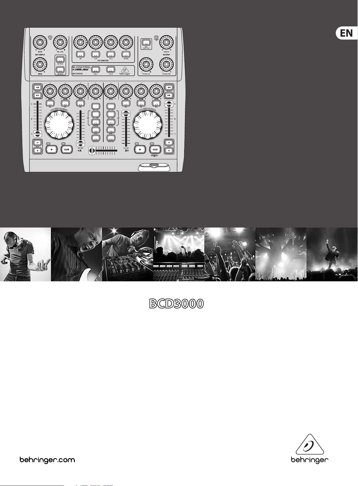
User Manual
B-CONTROL DEEJAY
Next-Generation DJ Machine—Play, Mix,
Perform and Scratch Your MP3 Files like Vinyl Records
Page 2

2 B-CONTROL DEEJAY BCD3000 User Manual
Table of Contents
Thank you .......................................................................2
Important Safety Instructions ...................................... 3
Legal Disclaimer ............................................................. 3
Limited warranty ............................................................ 3
1. Introduction ............................................................... 4
2. Installation ................................................................. 5
3. Control Elements and Connections ......................... 6
4. The Software .............................................................. 8
5. Operation ................................................................. 10
6. MIDI Control ............................................................. 12
7. Audio Connections .................................................. 14
8. Specications ........................................................... 15
Thank you
Thank you for expressing your condence in us by purchasing the B-CONTROL.
The BCD3000 is a 4-channel audio interface, and enables control over virtually
all current DJ applications by using the powerful virtual mixer (TRAKTOR 3 LE
software included). Despite its compact size, it oers a fully tted controller
console with 24-bit A/D und D/A converters, a full-speed USB audio interface
with a high-grade microphone preamplier, a 3-band kill EQ for each channel,
ultra-precise faders, a smooth crossfader and talkover function.
Page 3
3 B-CONTROL DEEJAY BCD3000 User Manual
9. Do not defeat the safety purpose of the polarized
UNDERTAKING OR REPRESENTATION. THIS MANUAL
Important Safety Instructions
Terminals marked with this symbol carry
electrical current of su cient magnitude
to constitute risk of electric shock.
Use only high-quality professional speaker cables with
¼" TS or twist-locking plugs pre-installed. Allother
installation or modi cation should be performed only
by quali edpersonnel.
This symbol, wherever it appears,
alertsyou to the presence of uninsulated
dangerous voltage inside the
enclosure-voltage that may be su cient to constitute a
risk ofshock.
This symbol, wherever it appears,
alertsyou to important operating and
maintenance instructions in the
accompanying literature. Please read the manual.
Caution
To reduce the risk of electric shock, donot
remove the top cover (or the rear section).
No user serviceable parts inside. Refer servicing to
quali ed personnel.
Caution
To reduce the risk of re or electric shock,
do not expose this appliance to rain and
moisture. The apparatus shall not be exposed to dripping
or splashing liquids and no objects lled with liquids,
suchas vases, shall be placed on the apparatus.
Caution
These service instructions are for use
by quali ed service personnel only.
Toreduce the risk of electric shock do not perform any
servicing other than that contained in the operation
instructions. Repairs have to be performed by quali ed
servicepersonnel.
or grounding-type plug. A polarized plug has two blades
with one wider than the other. A grounding-type plug
has two blades and a third grounding prong. The wide
blade or the third prong are provided for your safety. Ifthe
provided plug does not t into your outlet, consult an
electrician for replacement of the obsolete outlet.
10. Protect the power cord from being walked on or
pinched particularly at plugs, convenience receptacles,
and the point where they exit from the apparatus.
11. Use only attachments/accessories speci ed by
themanufacturer.
12. Use only with the
cart, stand, tripod, bracket,
or table speci ed by the
manufacturer, orsold with
the apparatus. When a cart
is used, use caution when
moving the cart/apparatus
combination to avoid
injury from tip-over.
13. Unplug this apparatus during lightning storms or
when unused for long periods of time.
14. Refer all servicing to quali ed ser vice personnel.
Servicing is required when the apparatus has been
damaged in any way, such as power supply cord or plug
is damaged, liquid has been spilled or objects have fallen
into the apparatus, the apparatus has been exposed
to rain or moisture, does not operate normally, or has
beendropped.
15. The apparatus shall be connected to a MAINS socket
outlet with a protective earthing connection.
16. Where the MAINS plug or an appliance coupler is
used as the disconnect device, the disconnect device shall
remain readily operable.
IS COPYRIGHTED. NO PART OF THIS MANUAL MAY
BE REPRODUCED OR TRANSMITTED IN ANY FORM
OR BY ANY MEANS, ELECTRONIC OR MECHANICAL,
INCLUDING PHOTOCOPYING AND RECORDING OF ANY
KIND, FOR ANY PURPOSE, WITHOUT THE EXPRESS
WRITTEN PERMISSION OF MUSICGROUPIPLTD.
ALL RIGHTS RESERVED.
© 2012 MUSICGroupIPLtd.
Trident Chambers, Wickhams Cay, P.O. Box 146,
Road Town, Tor tola, British Virgin Islands
LIMITED WARRANTY
For the applicable warranty terms and conditions
and additional information regarding MUSIC Group’s
Limited Warranty, please see complete details online at
www.music-group.com/warranty.
1. Read these instructions.
2. Keep these instructions.
3. Heed all warnings.
4. Follow all instructions.
5. Do not use this apparatus near water.
6. Clean only with dry cloth.
7. Do not block any ventilation openings. Install in
accordance with the manufacturer’s instructions.
8. Do not install near any heat sources such as
radiators, heat registers, stoves, or other apparatus
(including ampli ers) that produce heat.
LEGAL DISCLAIMER
TECHNICAL SPECIFICATIONS AND APPEARANCES
ARE SUBJECT TO CHANGE WITHOUT NOTICE AND
ACCURACY IS NOT GUARANTEED. BEHRINGER IS
PART OF THE MUSIC GROUP MUSICGROUP.COM.
ALL TRADEMARKS ARE THE PROPERTY OF THEIR
RESPECTIVE OWNERS. MUSICGROUP ACCEPTS NO
LIABILITY FOR ANY LOSS WHICH MAY BE SUFFERED
BY ANY PERSON WHO RELIES EITHER WHOLLY OR
IN PART UPON ANY DESCRIPTION, PHOTOGRAPH
OR STATEMENT CONTAINED HEREIN. COLORS AND
SPECIFICATIONS MAY VARY FROM ACTUAL PRODUCT.
MUSIC GROUP PRODUCTS ARE SOLD THROUGH
AUTHORIZED FULLFILLERS AND RESELLERS ONLY.
FULLFILLERSAND RESELLERS ARE NOT AGENTS OF
MUSICGROUP AND HAVE ABSOLUTELY NO AUTHORITY
TO BIND MUSICGROUP BY ANY EXPRESS OR IMPLIED
Page 4

4 B-CONTROL DEEJAY BCD3000 User Manual
1. Introduction
The BCD3000 features 2 rst-class Phono preamps, one of which is switchable
to the CD input. The sophisticated Headphone section includes a PFL function
as well as the option to monitor the master output signal directly. Start/Stop,
Cue, Loop and Pitch-Bend have dedicated controls to support your intuitive
performance, plus 4 user-assignable controls and buttons are available in the
Eects section. Benet now from the huge potential that modern laptops have to
oer, with the real-time accessibility to digital sound les of dierent formats!
◊ The following user’s manual is intended to familiarize you with the
unit’s control elements, so that you can master all the functions.
After having thoroughly read the user’s manual, store it in a safe place
for future reference.
1.1 Before you get started
1.1.1 Shipment
The BCD3000 was carefully packed at the assembly plant to assure secure
transport. Should the condition of the cardboard box suggest that damage may
have taken place, please inspect the unit immediately and look for physical
indications of damage.
◊ Damaged equipment should NEVER be sent directly to us. Please inform
the dealer from whom you acquired the unit immediately as well
as the transportation company from which you took delivery.
Otherwise, all claims for replacement/repair may be rendered invalid.
◊ To assure optimal protection of your B-CONTROL during use or
transport, we recommend utilizing a carrying case.
◊ Please always use the original packaging to avoid damage due to
storage or shipping.
◊ Never let unsupervised children play with the B-CONTROL or with
its packaging.
◊ Please dispose of all packaging materials in an environmentally
friendly fashion.
1.1.3 Online registration
Please register your new BEHRINGER equipment right after your purchase
by visiting http://behringer.com and read the terms and conditions of our
warrantycarefully.
Should your BEHRINGER product malfunction, it is our intention to have it
repaired as quickly as possible. To arrange for warranty service, please contact
the BEHRINGER retailer from whom the equipment was purchased. Shouldyour
BEHRINGER dealer not be located in your vicinity, you may directly contact
one of our subsidiaries. Corresponding contact information is included in the
original equipment packaging (Global Contact Information/European Contact
Information). Should your country not be listed, please contact the distributor
nearest you. A list of distributors can be found in the support area of our website
(http://behringer.com).
Registering your purchase and equipment with us helps us process your repair
claims more quickly and eciently.
Thank you for your cooperation!
1.2 Features with Mac OS X
When using the BCD3000 with a Mac, there are several limitations in comparison
to using it with Windows.
• Hardware driver is not required.
• Input A is only switchable between the Microphone and Phono input by
using MIDI commands.
• The outputs are dedicated: channels 1-2 are always routed to MASTER OUT
and channels 3-4 are routed to PHONES.
• The properties of the MIDI interface and LED cannot be recongured.
• Control Panel software to control the latency is not required.
1.3 System requirements
Minimum system requirements for PC:
1.1.2 Initial operation
Please make sure the unit is provided with sucient ventilation, and never place
the B-CONTROL on top of an amplier or in the vicinity of a heater to avoid the
risk of overheating.
A power supply unit which meets the necessary safety requirements is enclosed
for connecting the B-CONTROL to the mains.
Important information for installation
◊ The sound quality may diminish within the range of powerful
broadcasting stations and high-frequency sources. Increase the
distance between the transmitter and the device, and use shielded
cables for all connections.
• Processor: Pentium III / Athlon XP 1 GHz
• 1 free USB port (USB 1.1 or higher)
• CD drive
• 512 MB RAM
• OS: Windows XP SP 2
Minimum system requirements for Mac:
• Processor: G4 1.5 GHz or Dual Core 1.6 GHz
• 1 free USB port (USB 1.1 or higher)
• CD drive
• 512 MB RAM
• OS: Mac OS X 10.4
Page 5
5 B-CONTROL DEEJAY BCD3000 User Manual
2. Installation
When using Windows XP, please continue with Chapter 2.1. Mac users continue
with Chapter 2.2.
2.1 Installation on Windows XP
First, install the driver on your computer. The driver is provided on the included
“BCD3000” CD-ROM.
2.1.1 Hardware installation on Windows XP
1. Connect the BCD3000 to a free USB port on your computer.
2. Start Windows XP.
3. Once your computer has booted, switch on the BCD3000 and wait for the
device to be detected by the system. The “Found New Hardware Wizard”
opens up.
4. Close all applications, in particular those running in the background, such as
virus scanner software.
5. Put the driver/software CD-ROM supplied with the unit into the
CD/DVDdrive.
6. In the rst window that opens up, select
“Automaticsoftwareinstallation” and click on “Next >”.
7. If the error message “Driver software has not passed Windows Logo testing”
appears, ignore it and click on “Continue anyway” to install the rst part
of the driver.
2.1.2 Installing TRAKTOR 3 LE on Windows XP
Installation:
1. Insert the “TRAKTOR 3 LE” CD in the CD/DVD drive.
2. Open Windows Explorer (My Computer > right mouse button > Explorer).
3. In Windows Explorer, select the drive containing the “TRAKTOR 3 LE”
CD(forexample, double-click “DVD drive (D:)”).
4. Double-click the setup le (.exe) to start the installation process.
5. Follow the on-screen installation instructions.
After the installation, the TRAKTOR 3 LE soft ware is ready for use.
Now, you can run the TRAKTOR 3 LE program via the Start menu:
Start>AllPrograms > Native Instruments TRAKTOR 3 LE > TRAKTOR 3 LE.
2.2 Installation on Mac OS X
2.2.1 Hardware installation on Mac OS X
1. Connect the BCD3000 to a free USB port of your Mac.
2. The BCD3000 is now ready for use.
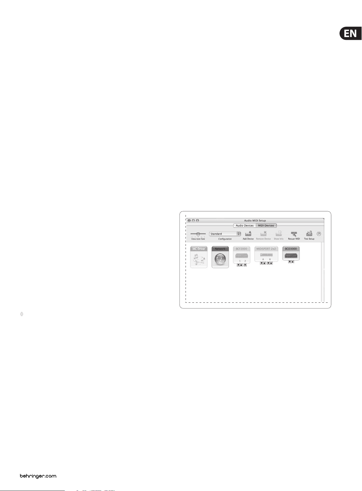
When “Audio MIDI Setup” is open, you see an icon for the BCD3000. You can
nd the Audio MIDI Setup application under Macintosh HD > Applications >
Utilities> Audio MIDI Setup.
8. Then click on “Finish”.
9. Now the installation window for the WDM driver of the BCD3000 appears
on the screen. Again, select “Automatic software installation” and click
on“Next >”.
10. If the error message is shown again (“Driver software has not passed
Windows Logo testing”), ignore it and click on “Continue anyway”.
11. The second part of the driver is installed.
12. Click on “Finish”.
The driver installation is complete. After a system reboot, the BCD3000 is ready
for use.
◊ Note for notebook users: If you encounter problems operating the
BCD3000 from your system, please disable the following settings:
1. In the Device Manager (right click on My Computer > Manage >
Device Manager), click option “Batteries” > disable Microsoft
ACPI-Compliant Control Method Battery.
2. In the USB Controller, do the following for each single USB Root Hub:
Right click > Properties > Power management > disable the option
“Allow the computer to turn off this device to save power”.
3. Restart Windows XP. Now the system performance of your computer
should be more stable.
Fig. 2.1: The BCD3000 in Audio M IDI Setup
2.2.2 Installing TRAKTOR 3 LE on Mac OS X
1. Insert the “TRAKTOR 3 LE” CD in the CD/DVD drive.
2. Double-click the TRAKTOR 3 LE CD icon to display the contents of the CD.
3. Double-click the TRAKTOR 3 LE setup le.
4. The program displays a welcome screen. Press “Continue”. A dialog appears
in which you can specify the type of installation and the target folder.
5. Follow the on-screen instructions.
After the installation, the TRAKTOR 3 LE soft ware is now ready for use.
You can run the TRAKTOR 3 LE program via Macintosh HD > Programs >
TRAKTOR 3 LE and double-click the “TRAKTOR 3 LE” icon.
Page 6
6 B-CONTROL DEEJAY BCD3000 User Manual
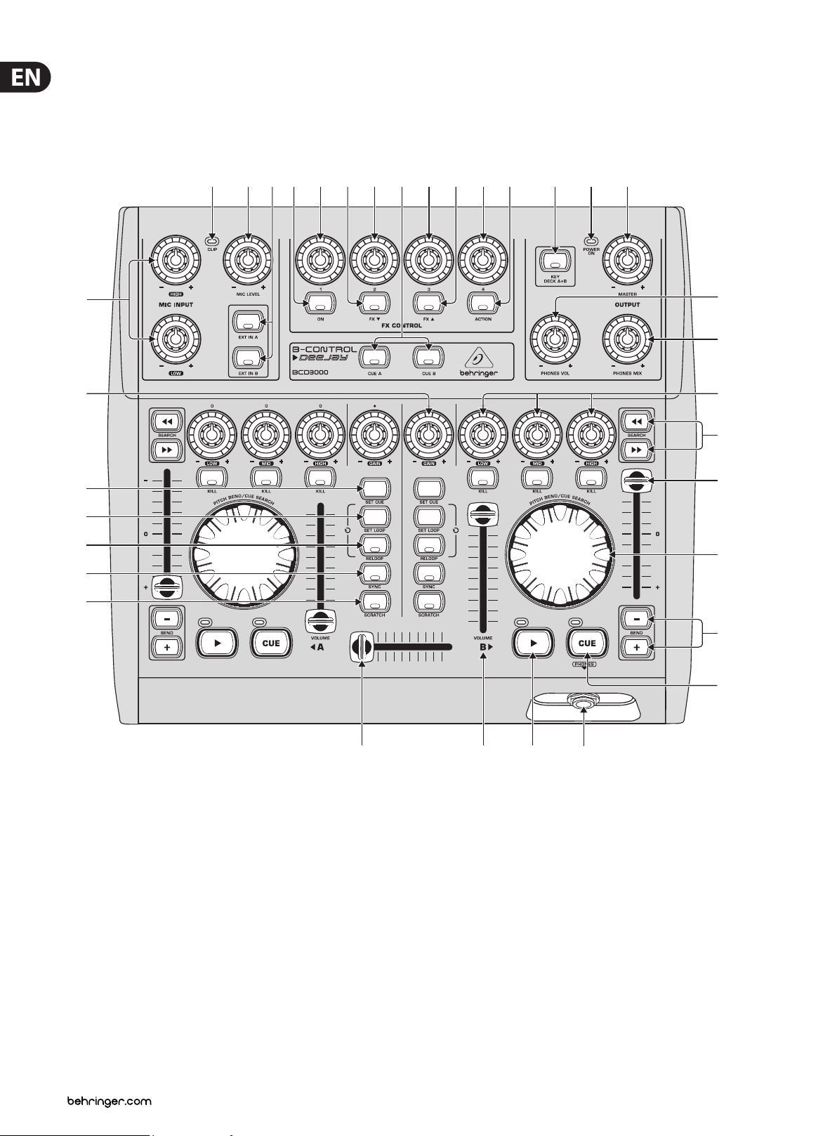
3. Control Elements and Connections
The various control elements of your BCD3000 are described in this chapter.
All controls and connections are explained in detail, and there are several useful
tips on their use.
(3)
(21)
(23)
(24)
(25)
(26)
(2) (1) (4) (9) (5)
(10)
(13) (11)
(6)
(7) (8)
(12) (17) (19) (18)
(15)
(16)
(22)
(33)
(32)
(34)
(27)
(20) (28) (29) (14)
Fig. 3.1: The BCD3000’s contro l elements
3.1 Control surface
The microphone input section (MIC INPUT)
(1) Set the volume of the microphone signal with the MIC LEVEL control.
(2) The CLIP LED illuminates as soon as the microphone signal level is too high
and could possibly cause audible distortion. If this happens, slightly turn the
MIC LEVEL control counter-clockwise.
(3) The microphone input section has a 2-band equalizer (EQ HIGH for high
frequencies and EQ LOW for low frequencies).
(4) Select the input source with the buttons EXT IN A / EXT IN B. If the buttons
are not pressed (LEDs are o ), the Deck A and B signals in the TRAKTOR 3LE
software are played back. If you press one of the buttons (LEDs light up),
theanalog input signal of the BCD3000 is passed on to the corresponding deck
in the TRAKTOR sof tware. On Deck A, the Phono input A (36) or microphone
signal is played back. On Deck B, you hear the input B signal (Phono or CD).
(31)
(30)
You can either specify the input source for Deck A in the Control
Panel (Windows only) or with MIDI commands (see Chapter 6.3).
For Deck B, selectthe input source on the rear panel of the device
(Phono/Lineswitch (38) ).
The FX CONTROL section
This section allows you to select and control eects with the BCD3000. In the
manual of the TRAKTOR 3 LE software (as PDF in the TRAKTOR 3 LE folder under
“Documentation”), you can nd the available eects.
(9) The ON button activates the eects section.
(10) The FX ▼ button switches to the preceding available eect.
(11) The FX ▲ button switches to the next available eect.
The assignment of the four controls (5) – (8)) and the AC TION
button (12) depends on the selected eect.
Page 7

7 B-CONTROL DEEJAY BCD3000 User Manual
The OUTPUT section
(13) The CUE A and CUE B buttons allow you to listen in on Deck A or B. Keepthe
respective button pressed to feed the signal of Deck A or Deck B to the
Headphone output (14).
(14) The PHONES output (¼" stereo connector) is used for
connectingheadphones.
(15) The PHONES VOL control lets you adjust the volume level of the
Headphoneoutput (14).
(16) The PHONES MIX control is used to adjust the relation between the stereo
MASTER OUT and MONITOR OUT signal. When the control is turned fully left,
you hear the MONITOR OUT signal, and when turned fully right, you hear the
MASTER OUT signal.
(17) The KEY DECK A + B button is used to activate the “Key Lock” function of
the TRAKTOR 3 LE sof tware. The “pitching” of a track usually changes both
the music’s speed (tempo) and pitch/key. The “Key Lock” function (or Master
Tempo) makes sure the pitch is retained. Find more on this topic in the PDF
manual of TRAKTOR 3 LE.
(18) Set the volume of the MASTER output with the MASTER OUTPUT control.
(19) The POWER ON-LED lights up when the BCD3000 is switched on.
The deck sections A and B
The control elements of decks A and B are the same. However, some of them are
grouped the opposite way round. We will therefore describe the elements to only
once. All of these control elements refer to the software functions which can be
“remotely” controlled from the BCD3000.
(20) The CROSSFADER is used to fade between deck A and deck B.
(29) Press the PLAY button to begin playback. Press this button a second time to
stop playback. By pressing PLAY again, playback continues from the point at
which it was stopped.
Every time playback is stopped, the cue point is placed at the current song
position. You can nd information on the CUE function in Chapter 5.2.
(30) Press the CUE button to stop playback and return to the last set cue point.
By keeping the CUE button pressed, the music begins at the cue point and
continues until you let go of the button. Then, the deck jumps back to the
cue point. You can nd information on the CUE function in Chapter 5.2.
(31) BEND buttons: Press the UP button (+) to increase the playback speed.
Pressthe DOWN button (–) to decrease the playback speed. This function
lets you match the beats of two playing tracks.
(32) The Pitch fader adjusts the playback speed seamlessly.
(33) Use the SEARCH buttons to move forward or backward in a song.
(34) The function performed by the scratch wheel depends on whether the deck
is in PLAY or PAUSE mode.
In PLAY mode, re-create the analog feel by using the wheel to nudge
(turnwheel to the right) or slow down (turn wheel to the left), allowingyou
to easily match the speed of the current deck to the speed of the other
deck playing. Press the SCRATCH button in order for you to scratch with
thewheel.
In PAUSE mode, you can use the wheel to move back and forth through the
song. You can also scratch with the wheel by pressing the SCRATCH button.
3.2 The rear panel
(21) The GAIN control allows you to adjust the deck signal to a nominal level.
(22) Each deck features a 3-band equalizer (HI, MID and LOW) with kill feature.
Thus, the signal can be attenuated to a much greater extent (-24 dB) than it
can be raised (+12 dB).
The KILL buttons, which are found below the EQ controllers, allow you
to cut out the relevant frequency range at the push of a button. This way
you can achieve interesting lter eects. The function is also required for
beatjuggling.
(23) The SET CUE button sets a cue point at the current position of the track
being played. This happens without interrupting playback. You can nd
information on the CUE function in Chapter 5.2.
(24) SET LOOP allows you to set the start and end points of a four-beat sequence
that is to be played back repeatedly (loop). The rst time this button is
pressed, the start point of the loop is set and the following four beats
are repeated as often as you like. Press the button a second time to stop
theloop.
(25) RELOOP is used to play a loop that you specied with SET LOOP
(24) beforehand. Press SET LOOP (24) once again to stop the loop.
(26) SYNC allows you to synchronize two tracks, which are running on Deck A and
B, by matching their speeds. The deck, which has its SYNC button pressed,
synchronizes itself automatically with the speed of the second deck.
(27) The Scratch Wheel (34) allows you to scratch while the deck is playing or
paused. Please press the SCRATCH button (LED lights up) in order to scratch.
(40)
Fig. 3.2: The re ar-panel audio conne ctors of the BC D3000
(39) (37) (35)(38) (36)
(35) MIC INPUT. The MIC IN connector is the balanced XLR input for your
dynamic microphone.
(36) The analog input A (PHONO) is used for connecting a turntable.
(37) Connect the ground cable on your turntable to the GND screw on the
BCD3000 housing.
(38) Analog input B. To connect a CD player or tape deck to this input, set the
switch to LINE.
(39) Connec t the MASTER OUTPUT to your power amplier. It provides the main
output signal, which can be adjusted with the MASTER control .
(40) SERIAL NUMBER.
(28) The VOLUME fader is used to adjust the volume level of the particular deck.
Page 8

8 B-CONTROL DEEJAY BCD3000 User Manual
(40)
(39) (37) (35)(38) (36)
(42) (41)
(43)
Fig. 3.3: POWER sw itch, mains and USB conne ctors
4. The Software
4.1 The TRAKTOR 3 LE software
The following gives you a short overview of the provided TRAKTOR 3 LE program.
A complete guide to working with the system (hardware and sof tware)
isfound in Chapter 5 as many of the program’s functions are controlled by the
B-CONTROL. A full description of the TRAKTOR 3 LE software is available in the
included TRAKTOR 3 LE manual. You can nd the manual as PDF document in
the TRAKTOR3 LE folder under “Documentation” (also from the Star t menu
inWindows).
(41) The USB connector is used for connecting to a computer with a compatible
USB port. The BCD3000 uses the USB connector to send and receive audio
and control data.
(42) A standard power socket is provided for connection to the mains. A matching
power cable is included with the unit.
(43) The POWER switch turns your BCD3000 on and o. It should always be in
the OFF position (out) when connecting the unit to or disconnecting the unit
from the mains.
◊ Please note: The power switch does not completely separate your
BCD3000 from AC power. If you plan on not using your BCD3000 for
a prolonged period of time, please disconnect it from the mains by
removing the power cable from the wall outlet.
Fig. 4.1: The TRAKTOR 3 LE ma in window
The TRAKTOR 3 LE user interface is split up into several sections: on the top half
of the screen, you see the decks on the right and lef t side, similar to the setup of
two CD players or turntables (Deck A on the left side and Deck B on the right side).
In between, you nd the mixer section with the crossfader and the level meters
for both decks.
On the bottom half, the List Browser is displayed on the left and the currently
selected list on the right.
Each deck displays the waveform of the track that is currently loaded.
Page 9

9 B-CONTROL DEEJAY BCD3000 User Manual
4.2 The Control Panel (Windows XP only)
The BCD3000 control panel allows you to control some general settings of the
BCD3000. The control panel will be available in the system as soon as the driver
has been installed and the BCD3000 has been connected and switched on.
Tostart the control panel software, click on the BCD3000 control panel symbol in
the task bar at the bottom right of your screen.
The following basic settings can be selected in the control panel:
GLOBAL MODE selection:
If STANDARD is selected, you can only adjust the input source for IN A
(MicorPhono A) and the driver latency on the ASIO page (see below).
Theoutputs are assigned as follows:
• CH 1-2: channels 1-2 are always routed to the MASTER OUT
• CH 3-4: channels 3-4 are always routed to the PHONES OUT
Additionally, the BCD3000’s MIDI characteristics dier from those in ADVANCED
mode (see below). In ADVANCED mode, all selection options are available in the
ASIO window.
The ASIO page:
Most people cannot hear latencies below 10 ms. When audio signals are
passing through a computer, it is impossible to achieve a 0-ms latency.
The WDM/MME page:
Fig. 4.3: The WDM/ MME window in the BCD300 0 control panel
Use the WDM/MME driver if your music sof tware does not support ASIO
(e.g.most software media players).
RECORD SELECT allows you to select BCD3000 input IN A or IN B for
2-channelrecording.
When you choose IN A, you can determine in the left-hand eld whether the
phono or microphone signal will be recorded.
Fig. 4.2: The A SIO window in the BCD300 0 control panel
This is where you adjust all parameters of the ASIO driver. The TRAKTOR 3 LE
software uses ASIO as is the case with most professional music applications.
You can only select one sof tware button per eld.
In the eld IN A (CH 1-2), you can select the input source to be routed to the
computer on channels 1-2 (Record).
In the MASTER OUT section, you can select the playback channels CH 1-2 or
CH3-4 for the main outputs (Playback).
In the PHONES OUT eld, you can select the playback channels CH 1-2 or CH 3-4
for the headphones connector (Playback).
Use Driver Latency to adjust the latency in order to optimize your computer’s
performance. If you set the control to “low” this will optimize the response
of your BCD3000, but also increase the processor workload. In extreme cases,
thiscan lead to clicking and drop-outs in the audio signal. The “mid” position
gives you a good compromise between processor workload and the response
time of the BCD3000. A “high” latency ensures trouble-free performance even
onslow computers.
◊ “Latency” is the time that elapses between an operator action on the
BCD3000 (e. g. pressing the PLAY button) and the actual output of the
audio signal from the OUT connectors. Latency depends on the system
used and the processing speed of your computer. Typical latencies
are in the milliseconds range (1 ms = one thousandth of a second).
PLAYBACK of this driver type is always stereo (channels 1-2). For this reason,
theMASTER OUT connectors on the rear panel and the PHONES connector on the
front panel always provide the same music signal.
The MIDI page:
Fig. 4.4: The MIDI wi ndow in the BCD3000 cont rol panel
On the MIDI page no parameters can be set. It only informs you about the various
MIDI modes, depending on the GLOBAL MODE selected:
In STANDARD mode, the buttons are “toggle o”, i. e. when you release a button
after pressing, the MIDI command is set back to its original value (like when you
release a key on a keyboard).
In STANDARD mode, all LEDs can be switched on and o individually with
specic MIDI commands.
In ADVANCED mode, all buttons are “toggle on”, i. e. press = “switch on”;
pressagain = “switch o” the MIDI function (similar to a light switch).
In ADVANCED mode, the response of the button LEDs depends on the respec tive
button, i. e. LED on = “function enabled”, LED o = “function disabled”.
Page 10

10 B-CONTROL DEEJAY BCD3000 User Manual
5. Operation
The control concept of the BCD3000 is designed to be extremely intuitive so
that you master it quickly. All control elements have been arranged in such a
way that you may already know from a DJ mixer or DJ CD player. The software’s
user interface reects the console of the BCD3000, allowing you to immediately
control as many functions as possible with the B-CONTROL, without having to use
the computer’s mouse.
5.1 First steps
Wiring
First of all, connect all the devices you need to the BCD3000. Make sure the unit
is o before connecting it to other equipment. If you want to use the BCD3000
without additional audio sources (CD player, turntable, microphone), you only
need to wire the outputs:
EP2000
EUROLIVE
B1520-PRO
EUROLIVE
B1520-PRO
Program launch
After you have successfully installed the driver and TRAKTOR 3 LE software,
runthe program. First, boot your computer, and then switch on the BCD3000.
XP: The computer detects the driver and displays the Control Panel
icon. Startthe TRAKTOR 3 LE program from the Start Menu:
Start>AllPrograms > Native Instruments TRAKTOR 3 LE >
TRAKTOR3LE.
Mac: Go to Macintosh HD > Applications > TRAKTOR 3 LE and double-click
the program icon “TRAKTOR 3 LE”.
The output section
Set the volume of the MASTER output with the MASTER control. The MASTER
output always provides the signal routed to the crossfader.
Adjust the volume level of the headphones with the PHONES VOL
control (15). ThePHONES MIX control (16) lets you adjust the balance between
theMonitor/CUE signal (fully left) and the Master output signal (fully right).
The Track Collection
Create your own Track Collection by selecting the menu item Preferences
(topright) > Browser Preferences > Data Location. Click “Add” on the
bottom right of the dialog box, and then select the folder you want to add.
In addition to folders, you can also import single track titles or your iTunes library.
You can nd more information in the TRAKTOR 3 LE manual, which is on the CD.
Computer &
B-DJ Software
USB MASTER OUT
BCD3000
USB
AUDIO
Fig. 5.1: Standard wiring o f the BCD3000
BEHRINGER
HPX4000
Connect the MASTER output to your hi- system, a pair of active speakers or
the PA system in the club where you are playing. Connect your headphones to
the PHONES output . The BEHRINGER DJ headphones HPX4000 are particularly
wellsuited.
Load title
Load a song from the list by using the mouse to click on the title and drag it onto
Deck A. Alternatively, there are many other approaches, such as right-click or
Ctrl-click, by selecting the track and then pressing Return, or by using hot keys
(explained in the TRAKTOR manual).
Start playback
Move the crossfader fully to the left and start playback by pressing the PLAY
button of deck A. Select a second track, move it to deck B and start it by pressing
the PLAY button of deck B.
Pre-listen to next song
Listen in on the second tune with your headphones, turning up the PHONESVOL
control (15) and moving the PHONES MIX control to the right (for example,
centerposition). At rst you hear the MASTER signal (Deck A). As soon as you
press the CUE B button, the signal of Deck B is added to the headphones.
Nowyoucan adjust the balance between both deck signals with the
PHONESMIXcontrol (16).
Next, match the tempo of Deck B with the current MASTER signal of Deck A.
Thiscan be achieved in various ways.
• Adjust the speed with the Pitch fader (32).
• Use the Pitch Bend buttons below the Pitch fader (31).
• A third option is to turn the Scratch wheel (34) clockwise (quicker)
orcounterclockwise (slower).
Ideally, listen to the bass drum or snare. If they match, the beat is perfect.
TheBeat Mix indicator in the waveform display is a great help, or simply use the
Sync Slave function (button (26)).
Page 11

11 B-CONTROL DEEJAY BCD3000 User Manual
5.2 Additional DJ functions
CUE function
The CUE function lets you place a cue point within a piece of music. A cue point
marks the position in a tune that you can specify. This will primarily be a point in
the track to which you want to return later, in order to play the track from that
point, for example.
• When PLAY is pressed while a track is playing, the playback is paused and
the cue point is placed at the current position.
• With SET CUE, a cue point is placed at the current position without pausing
the playback of a track.
• Press the CUE button to stop the playing track and jump back to the last
placed cue point. Playback is interrupted in this case.
By pressing CUE, the Song Position cursor jumps back to the last selected
cue point. If no cue point has previously been selected, the cursor jumps
automatically to the beginning of the track.
Pitch Bend
The Pitch Bend function allows you to change the track’s speed so that it can
be matched to the second track being played on the other channel. There are
severalpossibilities:
• The Pitch fader is used to control the Pitch function of the software
application. Move the Pitch fader (32) up or down to decrease or increase
thespeed.
signal is fed into the software mixer and can be processed with all the decks’
real-time functions (such as EQ, cut-o lter, eects, fader, crossfader, etc.).
Controllingthese functions is just as intuitive as the internal mixing.
EP2000
EUROLIVE
B1520-PRO
XM1800S
Phono 1
MIC IN
MASTER OUT
EUROLIVE
B1520-PRO
Phono 2
• The Bend “+” and Bend “–” buttons (31) correspond to the software’s
function of the Pitch Bend button. Press one of these buttons to change the
speed for a short time.
• If the deck is in Play mode, you can also use the wheel to momentarily speed
up or slow down the song in order to synchronize it with the other deck.
Loop function
The Loop function, which is integrated into the TRAKTOR 3 LE software, can also
be controlled by the BCD3000. The following control elements are available for
this purpose:
• SET LOOP (24)
• RELOOP (25)
The rst time the SET LOOP button (24) is pressed, a 4-beat loop starts seamlessly
on the next beat—the LED of the RELOOP button lights up in this case. To stop
the loop, press the same button (SET LOOP (24)) again—the LED of the RELOOP
button goes out. The music continues at the end of the loop without any pause.
This loop is stored until you load a new song into the deck. Press the RELOOP
(25) button to call up the saved loop again. Press the SET LOOP button (24) to exit.
When the LED of the RELOOP button is o, press the SET LOOP button (24)
tospecify a new loop.
Sync
The Sync function is a tool in the TRAKTOR 3 LE software that synchronizes two
pieces of music for you. This function should be activated in the channel being
monitored or else the rhythm may be irregular, which would be very annoying.
Indoing so, the monitored tune is matched to the piece of music currently played.
BCD3000
USB
AUDIO
Fig. 5.2: Ex panding the stan dard setup
BEHRINGER
HPX4000
In this setup, the standard setup shown in g. 5.1 is expanded by adding two
turntables and a microphone. The connection to the computer and the other
peripheral devices is the same as in example 1.
Connect the outputs of the turntables to the inputs A and B. When using
input B, the PHONO/LINE switch needs to be in the “PHONO” position.
Optionally,youcan connect a CD player to input B. In this case, the PHONO/LINE
switch needs to be in the LINE position. Activate the inputs by pressing the input
source buttons EXTINA or EXT IN B (4). You are able to manage up to four
source signals by switching between the analog source and the sof tware signal.
You can connect a dynamic microphone by using the available MIC input,
whichhas an XLR connector. There is a MIC LEVEL control in the MIC INPUT
section with which you can adjust the volume level of the microphone
signal. TheEQ controls LOW and HIGH let you change the microphone signal
additionally. Whenlevels are too high, the Clip LED lights up and audible
distortion may occur. If this happens, turn the MIC LEVEL control to the lef t until
the LED does not light upanymore.
5.3 Extended Setup
The BCD3000 system can do without external drives and media, however, it is
possible to extend this setup of controller and software by adding a CD player
(which may already be available) or two turntables. In this case, the analog
The ANALOG INPUT A (36) is switchable between the microphone signal and
PHONO A. This can be done the following ways:
• Via MIDI Program Change command (see Table 6.7)
• In Windows XP, via the tab “ASIO” or “WDM/MME” in Control Panel
Page 12

12 B-CONTROL DEEJAY BCD3000 User Manual
BCD3000
Hardware
BCD3000
Hardware
Windows Software
MIC IN
IN A (PHONO)
IN B
PHONO
LINE
MIC
PHONO A
IN A
CH 1-2
CH-3-4
MASTER OUT
PHONES OUT
CH 1-2
CH-3-4
ASIO
Windows Driver
ASIO
Windows Driver
CONTROL PANEL
Windows Software
OUT
IN
CONTROL PANEL
MIC IN
IN A (PHONO)
IN B
PHONO
LINE
MIC
PHONO A
CH 1-2
CH-3-4
CH 1-2
CH 3-4
CH 1-2
CH 3-4
MAST OUT
PHNS OUT
PHONES OUT
CH 1-2
CH 3-4
IN A
BCD3000
Hardware
BCD3000
Hardware
Windows Software
ASIO
Windows Driver
ASIO
Windows Driver
CONTROL PANEL
Windows Software
OUT
IN
CONTROL PANEL
MASTER OUT
MASTER OUTSTEREO
(CH 1-2)
PHONES OUT
MIC IN
IN A (PHONO)
IN B
PHONO
LINE
MIC
PHONO A
IN A
IN B
REC
SELECT
STEREO
(CH 1-2)
BCD3000
Hardware
BCD3000
Hardware
Windows Software
WDM/MME
Windows Driver
WDM/MME
Windows Driver
CONTROL PANEL
Windows Software
OUT
IN
CONTROL PANEL
MIC IN
IN A (PHONO)
IN B
PHONO
LINE
MIC
PHONO A
Prog Chg 0
Prog Chg 1
CH 1-2
CH-3-4
MASTER OUT
PHONES OUT
CH 1-2
CH-3-4
BCD3000
Hardware
BCD3000
Hardware
Mac OS X
Core Audio
Mac OS X
Core Audio
Mac OS X
OUT
IN
MIDI COMMAND
5.4 Signal routing
With the USB interface, you can record and play back up to four audio signals
simultaneously. The signal routing is specied by the settings of the applied
software (for example, TRAKTOR 3 LE), Control Panel and the state of the buttons
on the device.
In Windows, the possibilities of signal routing depend on the chosen driver
(ASIOor WDM/MME).
5. 4.1 Routing possibilities with the ASIO
driver(Windows)
STANDARD Mode:
If “STANDARD” is selected in the GLOBAL MODE of Control Panel, only the input
signals can be selected. The output assignment is precongured. The software
outputs 1-2 are routed to the MASTER OUTPUT (39) (rear panel) and the sof tware
outputs 3-4 are routed to the PHONES output (14) (front panel). Usually, it is
recommended to use the STANDARD mode, which is also the case when using the
TRAKTOR 3 LE software.
Playback with the WDM/MME driver is always in stereo, which is why the MASTER
output and the PHONES connector of the BCD3000 provide the same music signal.
Fig. 5.5: Audio rou ting with the WDM/M ME driver
5.4.3 Routing possibilities (Mac OS X)
With Mac, the BCD3000 always runs in the “STANDARD” mode, which means
that only the input signals can be congured. For channel IN A, you can assign
Mic or Phono A with MIDI commands in an appropriate software (seeTable6.7).
Theinput source for IN B (CH 3-4, Phono or Line) is selected with the
PHONO/LINE switch (38) on the rear panel of the BCD3000.
The output assignment is precongured. The software outputs 1-2 are routed to
the MASTER OUTPUT (39) (rear panel) and the software outputs 3-4 are routed to
the PHONES output (14) (f ront panel).
Fig. 5.3: Audio routing in STANDARD mode (ASIO driver)
Advanced Mode:
In Advanced mode, all parameters of the ASIO driver can be adjusted.
InControlPanel, you can select the input source for channel IN A (CH 1-2, Micor
PhonoA). The input source for IN B (CH 3-4, Phono or Line) is selected with
the PHONO/LINE switch (38) on the rear panel of the BCD3000. The playback
channels CH1-2or CH3-4 are also selected in Control Panel for the main outputs
(39) and the headphone output (14) (in the MASTER OUT and PHONESOUT
elds). If you assign the software output channels 1-2 to the headphone
output, thechannels 3-4 are automatically assigned to the MASTER OUTPUT,
and vice versa.
Fig. 5.4: Audio rou ting in Advanced Mod e (ASIO)
5.4.2 Routing possibilities with the WDM/MME
driver(Windows)
Fig. 5.6: Audio routing on the Mac
6. MIDI Control
All control functions of the BCD3000 are sent to your computer as MIDI data.
TheMusical Instruments Digital Interface is a generic, non-manufacturerspecic standard that enables communication between electronic musical
instruments. Although the BCD3000 is not equipped with the “classic” 5-pin
MIDI connectors, it still uses the MIDI protocol for data transmission via USB.
Thus,theBCD3000 can also control third-party software, as long as it is able to
“speak” MIDI. In turn, the BCD3000 can receive MIDI data and use them to show
the switching status of the button LEDs.
Primarily, two MIDI data types are used: Control Change (CC no.) and Note
commands (Note no.). The CC commands allow values, which change
continuously, to be transmitted in real time. Button functions are sent with
Note commands. You can match the MIDI commands to the software functions
in the DJ software of your choice. Please note that the dierent behaviors of
the LED control and the buttons’ Toggle On/O mode depend on the selected
GLOBALMODE, as explained in Chapter 4.2 under “The MIDI Tab”.
6.1 Sending control change functions
The WDM/MME driver supports playback/recording of 2 audio signals.
For2-channel recording you can select input IN A or IN B in the WDM/MME
window of the control panel. When you choose IN A, you can also determine the
signal to be recorded (Phono A or MIC).
When you select IN B, you can use the PHONE/LINE switch to determine the
signal to be recorded (phono or line).
All rotary knobs, faders, wheels and the crossfader are control elements that
send CC data. A CC number is assigned to each control element; the transmitted
absolute values range between 0 and 127. The Scratch wheels are the exception,
owing to the fact that continuous encoders do not transmit absolute values.
Theysend value changes (increment = +1, decrement = -1) when used.
Thefollowing table shows the regular assignment of CC numbers categorized in
function groups.
Page 13

13 B-CONTROL DEEJAY BCD3000 User Manual
Rotary control functions:
Preset FX MIDI CC no.
LOW (EQ)
DECK A
DECK B
FX CONTROL
OUTPUT PHONES MIX 17
Table 6.1: MIDI commands for transmitting rotary control func tions
MID (EQ)
HIGH (EQ)
GAIN
LOW (EQ)
MID (EQ)
HIGH (EQ)
GAIN
Data 1
Data 2
Data 3
Data 4
3
4
5
6
7
8
9
10
13
14
15
16
Innitely variable encoder functions:
Group Name MIDI CC no.
DECK A
DECK B
* The Scratc h wheels only send +1/-1 impulses (In c/Dec): left t urn value 63, right value 65. Whe n the
acceleratio n function is ac tivated (pres et after swi tching on), the value change can als o be larger; this dep ends
on the whee l’s speed when scrolle d manually (see Chapter 6 .3).
Table 6.2: MIDI commands for transmitting innitely variable encoder functions
PITCH BEND/
CUE SEARCH WHEEL
PITCH BEND/
CUE SEARCH WHEEL
19*
18*
Fader functions:
Group Name MIDI CC no.
DECK A
DECK A< >B CROSS Fader 1
DECK B
Table 6.3: MIDI commands for transmitting fader functions
PITCH Fader
VOLUME Fader
PITCH Fader
VOLUME Fader
11
0
12
2
Group Name MIDI note no. MIDI note name
DECK A S EA RC H <<
S EA RC H >>
BEND BEND +
LOW CUT
MID CUT
HIGH CUT
SET CUE
SEY LOOP
RELOOP
SYNC
SCRATCH
PL AY
CUE
DECK B S EA RC H <<
S EA RC H >>
BEND BEND +
LOW KILL
MID KILL
HIGH KILL
SET CUE
SEY LOOP
RELOOP
SYNC
SCRATCH
PL AY
CUE
INPUT SELECT EXT IN A
EXT IN B
FX CONTROL ON (FX unit ac tive)
FX ▼ (preset down)
FX ▲ (preset up)
ACTION (or TAP)
CUE SELECT CUE A
CUE B
KEY DECK A+B KEY DECK A+B* 28 E 1
* Activat es the Time Stretch mo de for Decks A+B simu ltaneously.
Table 6.4: MIDI commands for transmitting button functions
0
1
2
3
12
13
14
4
15
5
16
17
18
19
6
7
8
9
20
21
22
10
23
11
24
25
26
27
29
30
31
32
33
34
35
36
C -1
C# -1
D -1
D# -1
C 0
C# 0
D 0
E -1
D# 0
F -1
E 0
F 0
F #0
G 0
F# -1
G -1
G# -1
A -1
G #0
A 0
A# 0
A# -1
B 0
B -1
C 1
C# 1
D 1
D# 1
F 1
F# 1
G 1
G# 1
A 1
A# 1
B 1
C 2
6.3 Receiving MIDI commands
6.2 Sending button functions
All switching elements (buttons) of the BCD3000 transmit MIDI note commands.
When you press a button, the system sends a “note on” command, togetherwith
the corresponding note number. When the button is released, the system
transmits a “note o” command.
Press (and hold) a button = note on / release a button = note o.
(For a permanent note-on command, please select “toggle on” in the software.)
The reception of MIDI data also allows for transmitting commands from
third-party DJ software to your BCD3000. Although this function is not necessary
to control the device from the software, you can still display the switching status
of button LEDs, which enables you to work more intuitively.
All button LEDs receive MIDI control change data (on/o). If the controller value
transmitted is between 0 and 63, this value corresponds to the switched-o
status (LED o). If the value is 64 or higher (max. 127), the LED illuminates.
Page 14

14 B-CONTROL DEEJAY BCD3000 User Manual
Group Name MIDI CC no.
DECK A LOW KILL
MID KILL
HIGH KILL
RELOOP
SYNC
SCRATCH
PL AY
CUE
DECK B LOW KILL
MID KILL
HIGH KILL
RELOOP
SYNC
SCRATCH
PL AY
CUE
INPUT SELECT E XT IN A
EXT IN B
FX CONTROL ON (F X unit active)
FX ▼ (preset down)
FX ▲ (preset up)
ACTION (or TAP)
CUE SELECT CUE A
CUE B
KEY DECK A+B KE Y DECK A+B* 25
Table 6.5: MIDI comman ds for receiving b utton LED statu ses
24
23
22
21
20
19
18
17
16
15
14
13
12
11
10
9
8
7
6
5
4
3
2
1
In case you want to deactivate the acceleration when using other MIDI
software applications, apply a MIDI command that is transmitted from the MIDI
application to the BCD3000. After doing so, the value changes will be constant
when scrolling the wheel (left turn: 63, right turn: 65), regardless how quick.
MIDI channel MIDI CC no. Value Behavior
0-63 Wheels Acce leration = o
CH. 1 99
Table 6.8: Switchi ng between whe els’ acceleration s
64 -127
Wheels Acce leration = on
(default)
7. Audio Connections
You will need a large number of cables for dierent applications. The illustrations
below show how the connectors should be wired. Be sure to use only
high-gradecables.
The microphone input of the BCD3000 is electronically balanced to avoid
humproblems.
Of course, you can also connect unbalanced microphones to the balanced input.
In this case, connect pin 1 and pin 3.
Balanced use with XLR connectors
12
3
Data request for all moving elements:
If the “Data Request ” command (demand for data) is sent from a suitable
software application to the BCD3000 as “Control Change” command (100)
onMIDI channel 1, the B-CONTROL transmits its current controls settings to the
MIDI or DJ software application. This aects all knobs and faders apar t from both
wheels and buttons.
MIDI channel MIDI CC no.
CH. 1 100
Table 6.6: Control ler for data reque st
Selecting the input channel:
You can select the analog input A (see chapter 2.3) via MIDI. To do this,
aprogram change command must be sent to the BCD3000.
ANALOG INPUT A
selection
PHONO A IN CH. 1 Program Change 0
MIC IN CH. 1 Progr am Change 1
Table 6.7: Switching th e analog input using p rogram change com mands
MIDI channel MIDI message
Acceleration behavior of the Wheels:
Both wheels are automatically selected when the acceleration option is switched
on. The quicker you turn one of the wheels, the stronger the value changes.
InTRAKTOR 3 LE, this means the following:
input
1 = ground/shield
2 = hot (+ve)
3 = cold (-ve)
1
2
3
output
For unbalanced use, pin 1 and pin 3
have to be bridged
Fig. 7.1: XLR connector
¼" TRS headphones connector
strain relief clamp
sleeve
ring
tip
sleeve
ground/shield
ring
right signal
tip
left signal
Fig. 7.2: ¼" TRS headphones connector
• In PLAY mode, you can speed up or slow down the track quicker
• In PAUSE mode, you can move quicker through the track
The value change relates directly to the wheel’s speed when scrolled manually.
When the SCRATCH button is activated, the acceleration is temporarily turned o
in order to ensure an optimum scratch behavior.
Page 15

15 B-CONTROL DEEJAY BCD3000 User Manual
8. Specications
Audio Inputs
Microphone Input
Type XLR balanced
Gain range -∞ - +50 dB
Frequency response 10 Hz - 29 kHz (-3 dB)
Impedance approx. 2 kΩ (balanced)
Max. input level -25 dBu @ 35 dB Gain
(mic level centerposition)
Signal-to-noise ratio 110 dB (A-weighted)
Distortion (THD + N) 0.01% (A-weighted)
CMRR typ. -40 dB
Equalizer
EQ low ±12 dB @ 40 Hz
EQ high ±12 dB @ 12 kHz
Line Inputs
Phono in 40 dB Gain
Line in 0 dB Gain
Impedance approx. 47 kΩ
USB Interface
Type Full-Speed 12 MBit/s
System Specications
Signal-to-noise ratio >80 dB
Crosstalk <80 dB
Distortion (THD) 0.01%
Frequency response 15 Hz - 21 kHz, +0/-3 dB
Power Supply
Voltage 100 - 240 V~, 50/60 Hz
Power consumption max. 7 W
Fuse T 1 A H 250 V
Mains connection Standard IEC receptacle
Dimensions/Weight
Dimensions (H x W x D) 13 x 3.9 x 11.8"
330 x 100 x 300 mm
Weight approx. 5.5 lbs / 2.5 kg
Max. input level +12 dBu
Audio Outputs
Master Out
Type RCA
Impedance 120 Ω
Signal-to-noise ratio 101 dB
Crosstalk <80 dB @ 1 kHz
Max. output level +18 dBu
Phones Out
Type ¼" TRS connector
Max. output level +4.7 dBu (+18.2 dBm) @ 30 Ω loading
Digital Processing
Converter 24 Bit
Sample rate 44.1 kHz
Signal-to-noise ratio A/D: 100 dB
D/A: 100 dB
BEHRINGER i s constantly str iving to maintain the h ighest profess ional standards. A s a result of these e ffort s,
modific ations may be made f rom time to time to exi sting product s without prio r notice. Specif ications and
appearance m ay differ fro m those listed or illus trated.
Page 16

16 B-CONTROL DEEJAY BCD3000 User Manual
FEDERAL COMMUNICATIONS
COMMISSION COMPLIANCE
INFORMATION
B-CONTROL DEEJAY BCD3000
Responsible Party Name: MUSIC Group Services US Inc.
Address: 18912 North Creek Parkway,
Suite 200 Bothell, WA 98011,
USA
Phone/Fax No.: Phone: +1 425 672 0816
Fax: +1 425 673 7647
B-CONTROL DEEJAY BCD3000
complies with the FCC rules as mentioned in the followingparagraph:
This equipment has been tested and found to comply with the limits for a ClassB
digital device, pur suant to part 15 of the FCC Rules. These limits are designed
to provide reasonable protection against harmful interference in a residential
installation. This equipment generates, uses and can radiate radio frequency
energy and, if not installed and used in accordance with the instruc tions, may cause
harmful interference to radio communications. However, there is no guarantee that
interference will not occur in a particular installation. If this equipment does cause
harmful interference to radio or television reception, which can be determined
by turning the equipment o and on, the user is encouraged to try to correct the
interference by one or more of the followingmeasures:
• Reorient or relocate the receiving antenna.
• Increase the separation between the equipment and receiver.
• Connect the equipment into an outlet on a circuit dierent from that to which the
receiver is connected.
• Consult the dealer or an experienced radio/TV technician forhelp.
This device complies with Part 15 of the FCC rules. Operation is subject to the
following two conditions:
(1) this device may not cause harmful interference, and
(2) this device must accept any inter ference received, including inter ference that may
cause undesired operation.
Important information:
Changes or modications to the equipment not expressly approved by MUSIC Group
can void the user’s authority to use the equipment.
Page 17

We Hear You
 Loading...