

Page 1
Documentation | EN
KM6551
Terminal module for wireless data exchange
2021-03-03 | Version: 2.0.0
Page 2

Page 3

Table of contents
Table of contents
1 Foreword ....................................................................................................................................................5
1.1 Notes on the documentation..............................................................................................................5
1.2 Safety instructions .............................................................................................................................6
1.3 Documentation issue status ..............................................................................................................7
2 Product overview.......................................................................................................................................8
2.1 Introduction........................................................................................................................................8
2.2 Technical data ...................................................................................................................................9
2.3 Basic Function Principles ................................................................................................................10
2.4 LED displays....................................................................................................................................12
2.5 DIP switch........................................................................................................................................13
3 IEEE802.15.4 ............................................................................................................................................14
3.1 Introduction......................................................................................................................................14
3.2 Interference caused by other radio systems....................................................................................15
4 Mounting and wiring................................................................................................................................17
4.1 Recommended mounting rails.........................................................................................................17
4.2 Mounting and demounting - terminals with traction lever unlocking ................................................17
4.3 Dimensions......................................................................................................................................19
4.4 Connection ......................................................................................................................................19
4.5 Antenna alignment...........................................................................................................................21
4.5.1 Directional characteristic.................................................................................................. 21
4.5.2 Alignment examples ........................................................................................................ 23
4.5.3 Polarization ...................................................................................................................... 23
4.5.4 Placement of the antennas .............................................................................................. 24
4.6 Attenuation and range .....................................................................................................................25
4.6.1 Fresnel zone .................................................................................................................... 25
4.6.2 Attenuation in practice ..................................................................................................... 26
4.6.3 Range of different antenna combinations ........................................................................ 26
4.7 Antennas .........................................................................................................................................27
4.7.1 ZS6100-0900 ................................................................................................................... 28
4.7.2 ZS6100-1800 ................................................................................................................... 30
4.7.3 ZS6200-0400 ................................................................................................................... 32
4.7.4 ZS6201-0410 ................................................................................................................... 34
4.7.5 ZS6201-0500 ................................................................................................................... 36
5 Application examples - overview ...........................................................................................................38
5.1 Peer to peer mode...........................................................................................................................38
5.2 Master-Slave mode .........................................................................................................................38
5.3 Broadcast mode ..............................................................................................................................39
5.4 Energy scan.....................................................................................................................................40
6 TwinCAT ...................................................................................................................................................42
6.1 TwinCAT libraries ............................................................................................................................44
6.2 TwinCAT examples .........................................................................................................................44
6.3 Function blocks................................................................................................................................45
6.3.1 Function block FB_KM6551_MAIN.................................................................................. 45
KM6551 3Version: 2.0.0
Page 4

Table of contents
6.3.2 Energy scan..................................................................................................................... 46
6.3.3 Master/Slave mode.......................................................................................................... 47
6.3.4 Broadcast mode............................................................................................................... 49
7 KS2000 Configuration Software.............................................................................................................52
7.1 KS2000 - Introduction......................................................................................................................52
7.2 Parameterization with KS2000 ........................................................................................................53
7.3 Settings............................................................................................................................................55
7.4 Register ...........................................................................................................................................56
7.5 Process data....................................................................................................................................57
8 Access from the user program ..............................................................................................................59
8.1 Process image.................................................................................................................................59
8.2 Control and Status Bytes.................................................................................................................59
8.2.1 Process data mode.......................................................................................................... 59
8.2.2 Register communication .................................................................................................. 61
8.3 Register overview ............................................................................................................................62
8.4 Register description.........................................................................................................................63
8.5 Examples of Register Communication ............................................................................................65
8.5.1 Example 1: reading the firmware version from Register 9............................................... 65
8.5.2 Example 2: Writing to an user register............................................................................. 66
9 Appendix ..................................................................................................................................................69
9.1 General operating conditions...........................................................................................................69
9.2 EC declaration of conformity ...........................................................................................................71
9.3 Calculating with decibels .................................................................................................................72
9.4 Support and Service ........................................................................................................................72
KM65514 Version: 2.0.0
Page 5

Foreword
1 Foreword
1.1 Notes on the documentation
Intended audience
This description is only intended for the use of trained specialists in control and automation engineering who
are familiar with the applicable national standards.
It is essential that the documentation and the following notes and explanations are followed when installing
and commissioning these components.
It is the duty of the technical personnel to use the documentation published at the respective time of each
installation and commissioning.
The responsible staff must ensure that the application or use of the products described satisfy all the
requirements for safety, including all the relevant laws, regulations, guidelines and standards.
Disclaimer
The documentation has been prepared with care. The products described are, however, constantly under
development.
We reserve the right to revise and change the documentation at any time and without prior announcement.
No claims for the modification of products that have already been supplied may be made on the basis of the
data, diagrams and descriptions in this documentation.
Trademarks
Beckhoff®, TwinCAT®, EtherCAT®, EtherCATG®, EtherCATG10®, EtherCATP®, SafetyoverEtherCAT®,
TwinSAFE®, XFC®, XTS® and XPlanar® are registered trademarks of and licensed by Beckhoff Automation
GmbH. Other designations used in this publication may be trademarks whose use by third parties for their
own purposes could violate the rights of the owners.
Patent Pending
The EtherCAT Technology is covered, including but not limited to the following patent applications and
patents: EP1590927, EP1789857, EP1456722, EP2137893, DE102015105702 with corresponding
applications or registrations in various other countries.
EtherCAT® is registered trademark and patented technology, licensed by Beckhoff Automation GmbH,
Germany.
Copyright
© Beckhoff Automation GmbH & Co. KG, Germany.
The reproduction, distribution and utilization of this document as well as the communication of its contents to
others without express authorization are prohibited.
Offenders will be held liable for the payment of damages. All rights reserved in the event of the grant of a
patent, utility model or design.
KM6551 5Version: 2.0.0
Page 6
Foreword
1.2 Safety instructions
Safety regulations
Please note the following safety instructions and explanations!
Product-specific safety instructions can be found on following pages or in the areas mounting, wiring,
commissioning etc.
Exclusion of liability
All the components are supplied in particular hardware and software configurations appropriate for the
application. Modifications to hardware or software configurations other than those described in the
documentation are not permitted, and nullify the liability of Beckhoff Automation GmbH & Co. KG.
Personnel qualification
This description is only intended for trained specialists in control, automation and drive engineering who are
familiar with the applicable national standards.
Description of instructions
In this documentation the following instructions are used.
These instructions must be read carefully and followed without fail!
DANGER
Serious risk of injury!
Failure to follow this safety instruction directly endangers the life and health of persons.
WARNING
Risk of injury!
Failure to follow this safety instruction endangers the life and health of persons.
CAUTION
Personal injuries!
Failure to follow this safety instruction can lead to injuries to persons.
NOTE
Damage to environment/equipment or data loss
Failure to follow this instruction can lead to environmental damage, equipment damage or data loss.
Tip or pointer
This symbol indicates information that contributes to better understanding.
KM65516 Version: 2.0.0
Page 7

1.3 Documentation issue status
Version Comment
2.0.0 • Migration
• Structure update
1.2.0
1.1.0 • Register description extended
1.0.0 First release
Firmware and hardware versions
Documentation, version Firmware version Hardware version
2.0.0 1F 02
1.2.0 1E 01
1.1.0 1E 00
1.0.0 1B 00
• Included TwinCAT library [}44] updated to version 1.7.0
• Description of the KS2000 configuration software updated
• Notes on interference caused by other radio systems expanded
• Notes on mounting expanded
• Antenna ZS6201-0500 added
• Antenna descriptions updated
Foreword
The firmware and hardware versions (delivery state) can be taken from the serial number printed on the side
of the terminal module.
Syntax of the serial number
Structure of the serial number: WWYYFFHH
WW - week of production (calendar week)
YY - year of production
FF - firmware version
HH - hardware version
Example with serial number 35 05 00 01:
35 - week of production 35
05 - year of production 2005
00 - firmware version 00
01 - hardware version 01
KM6551 7Version: 2.0.0
Page 8

Product overview
2 Product overview
2.1 Introduction
Fig.1: KM6551-0000 - Terminal module for radio transmission
The KM6551-0000 terminal module is a data exchange unit based on radio technology. It uses the
IEEE802.15.4 standard. Data is exchanged or transmitted between two independent controllers via radio,
independent of the higher-level fieldbus. The free-field distance between two KM6551-0000 units can be up
to 300m.
The KM6551-0000 terminal module has a reverse SMA plug (Straight Medium Adapter), to which various
radio antennas [}27] can be connected, which are to be procured from Beckhoff. The directional
characteristic can be adapted to the surroundings by means of specifically selecting the antenna. Status and
data exchange are displayed via LEDs, thereby offering fast and simple diagnostics. A TwinCAT library
[}44] is available for the use of the KM6551-0000 terminal module with TwinCAT.
KM65518 Version: 2.0.0
Page 9

Product overview
2.2 Technical data
Technical data KM6551-0000
Frequency band 2.4GHz
Data transfer rates 250kbit
Output power 0dBm (1mW)
Reception sensitivity -87dBm
Protocol IEEE802.15.4
Antenna connection reverse SMA plug (RP_SMA)
Power supply for the electronics via the K-bus
Current consumption via K-bus typically 135mA
Width of a bus terminal block Maximum 64 standard Bus Terminals or 80cm
(one KM6551-0000 corresponds to 2 standard Bus Terminals
here)
Data width in the input process image 12bytes
Data width in the output process image 12bytes
Dimensions without antenna (W x H x D) approx. 26.5mm x100mm x 55mm (width aligned: 24mm)
Weight app.100g
Permissible ambient temperature range
during operation
Permissible ambient temperature range
during storage
Permissible relative air humidity 95%, no condensation
Mounting [}17] on a 35mm mounting rail [}17] (e.g. DIN rail TH35-7.5
Vibration/shock resistance conforms to EN60068-2-6/ EN60068-2-27, EN60068-2-29
EMC immunity/emission conforms to EN61000-6-2/ EN61000-6-4
Protection class IP20
Installation position variable
Approval CE
0°C ... + 55°C
-25°C ... + 85°C
conforming to EN60715)
KM6551 9Version: 2.0.0
Page 10
Product overview
2.3 Basic Function Principles
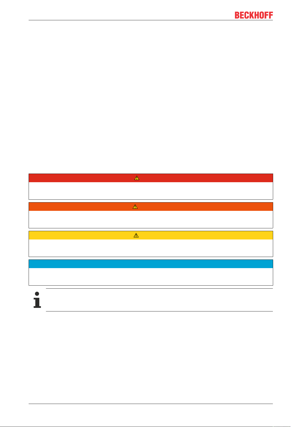
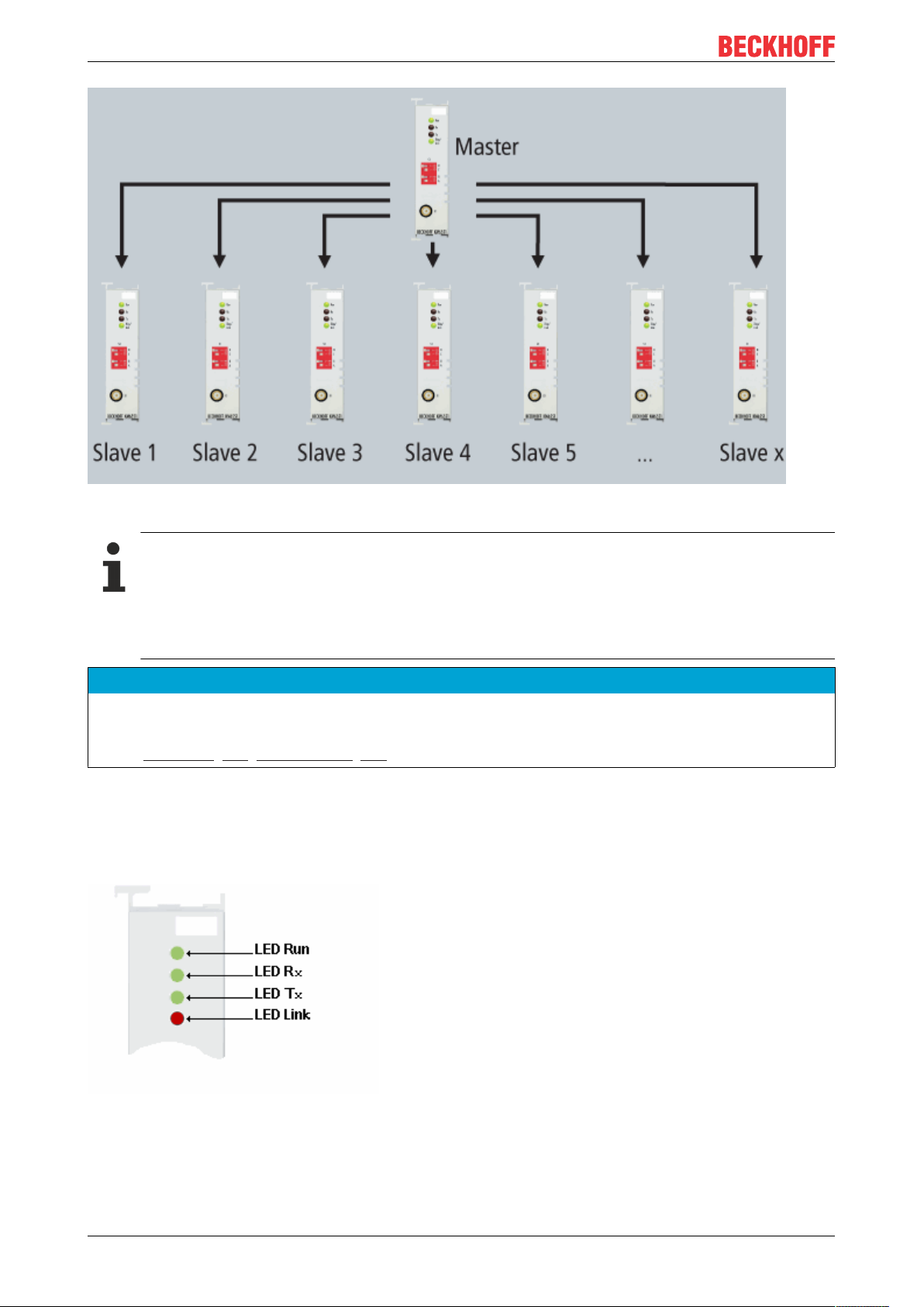
Fig.2: Basic Function Principles
The KM6551-0000 data exchange module enables the wireless exchange of data between two or more
controllers. It uses the IEEE802.15.4 standard as its basis with a Beckhoff-specific protocol. 10bytes of user
data are transmitted per data packet. The DIP switch is used to set the operating mode of the KM6551-0000,
i.e. whether the module functions as a master or slave and which communication mode is to be used.
The data is exchanged in the peer to peer and master-slave modes using the polling method. In broadcast
mode, one module is the broadcast master that sends the data and all other modules are broadcast slaves
that receive the data but cannot send data to the broadcast master themselves. Hence, they listen only to
data from the broadcast master.
In master-slave mode you can decide via the software with which slave data should be exchanged. Up to
7slaves can be addressed.
The data exchange module KM6551-0000 supports 16channels, which are freely selectable and can be
used, for example, to establish several radio networks or for placement outside WLANs or other radio
systems that also use 2.4GHz.
The KM6551-0000 can scan the possible 16 channels. The energy in the frequency range is measured to
ascertain in advance whether other systems are active and on which frequencies. Furthermore, the so-called
LQI (LinkofQualityIndex) is transmitted with each data telegram. This makes it possible to determine the
quality of the signal. A high LQI value indicates a good connection, a low value a poor connection. In order to
improve the LQI value, a larger antenna or an antenna with a correspondingly larger transmission factor can
be used.
Communication mode
The KM6551-0000 data exchange module supports three different communication modes.
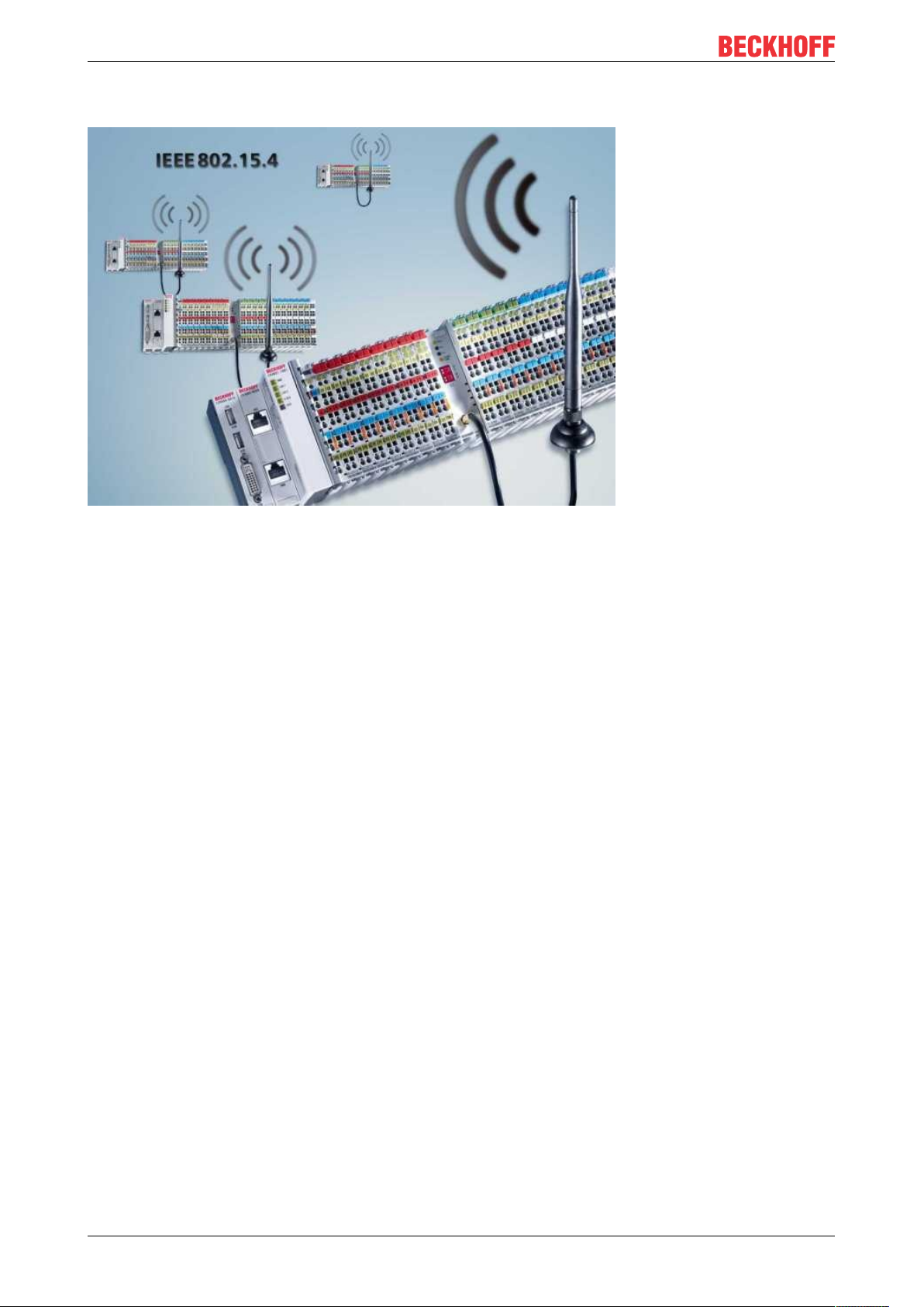
Mode 1: Peer to peer – data exchange between two modules
Enables the exchange of data between two KM6551-0000. A maximum of 10bytes of data can be
transmitted per cycle. In one cycle (typically < 20ms), module1 sends data to module2 and module2 sends
data back to module1.
KM655110 Version: 2.0.0
Page 11
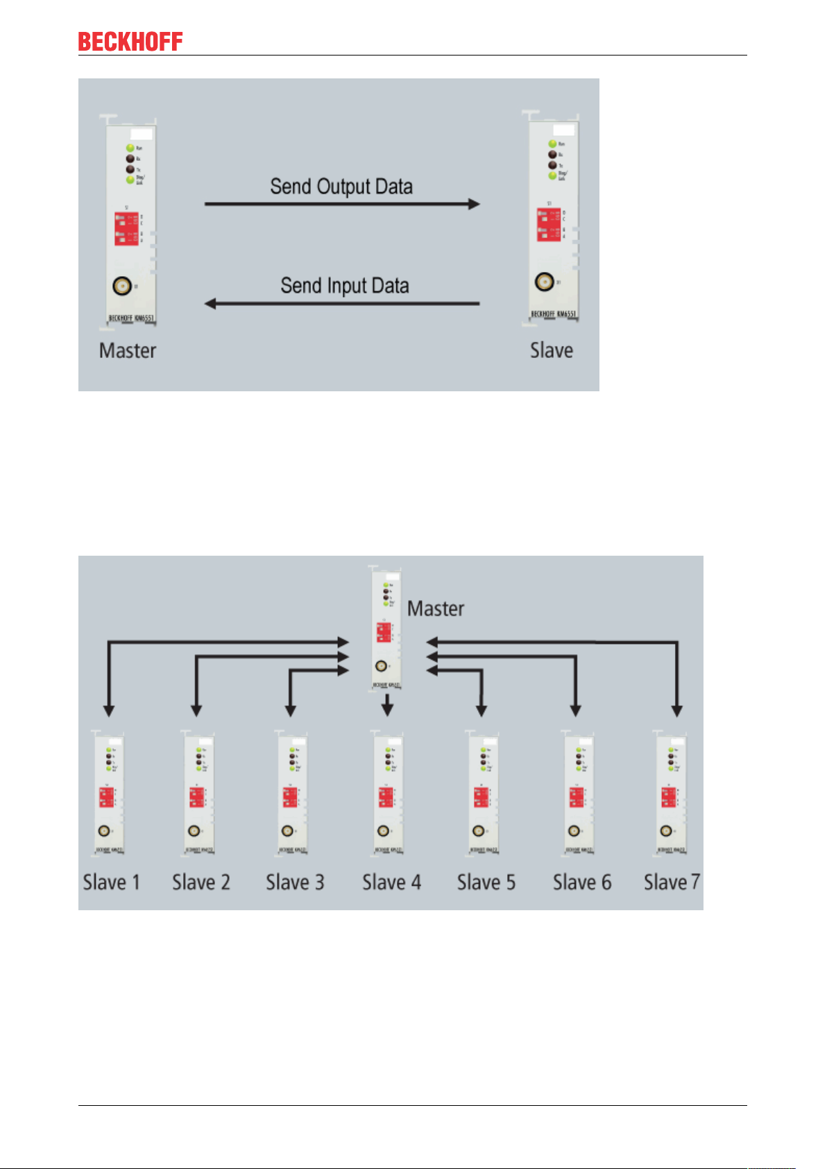
Fig.3: Peer to Peer
Product overview
Mode 2: Master-slave – data exchange between a master and up to 7slaves
In master-slave mode the master can communicate with up to seven KM6551-0000 using the polling
method. To do this, set the corresponding slave addresses using the DIP switch. From the PLC you can
inform the master which slave it should communicate with, how often and for how long. Approx. 20ms are
required per slave. For seven slaves this results in a minimum cycle time of 140ms which the master
requires in order to address all 7 slaves once each.
Fig.4: Master-Slave mode
Mode 3: Broadcast to any number of slaves
In broadcast mode, only the broadcast master transmits. All other modules (broadcast slaves) can only
receive data but cannot send data themselves. Any number (x) of broadcast slaves can listen in.
KM6551 11Version: 2.0.0
Page 12
Product overview
Fig.5: Broadcast mode
Support of the KM6551-0000 using Bus Couplers, Bus Terminal Controllers and
TwinCAT
The KM6551-0000 is supported from TwinCAT 2.10 Build 1326 onwards. The following Bus Couplers are supported: BK1120, BK1250, BK2020, BK3120, BK3150, BK9000, BK9050. (Further Bus
Couplers on request). All Bus Terminal Controllers from the BCxxxx, BXxxxx and BXxxxx series are
supported.
NOTE
CE conformity
The CE conformity of the KM6551-0000 is only guaranteed if it is operated with original Beckhoff accessories (antennas [}27], coaxial cable [}19])!
2.4 LED displays
KM6551-0000
Fig.6: KM6551 - LED displays
KM655112 Version: 2.0.0
Page 13
Product overview
LED Display
Run (green) off Data transmission on the K-bus is not active
on Data transmission on the K-bus is active
Rx (green) on Data being received via radio
Tx (green) on Data being sent via radio
Link (green, orange, red) on Green - good signal quality
Orange - moderate signal quality
Red - poor signal quality or watchdog has triggered
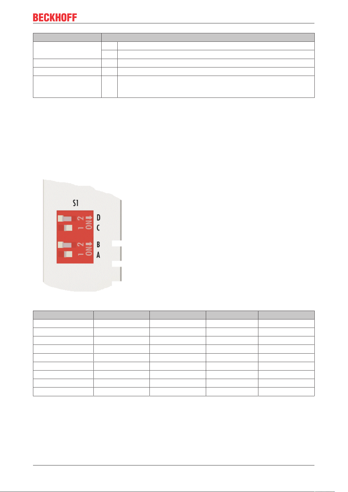
2.5 DIP switch
You can activate the different modes of the KM6551-0000 using the DIP switch. This enables the simple
exchange of the modules without additional configuration software.
• DIP switch in right position: ON
• DIP switch in left position: OFF
The picture illustrates the setting for Slave 5.
Fig.7: DIP switch
DIP switch A B C D
Master mode OFF OFF OFF OFF
Slave 1 ON OFF OFF OFF
Slave 2 OFF ON OFF OFF
Slave 3 ON ON OFF OFF
Slave 4 OFF OFF ON OFF
Slave 5 ON OFF ON OFF
Slave 6 OFF ON ON OFF
Slave 7 ON ON ON OFF
Broadcast slave OFF OFF OFF ON
KM6551 13Version: 2.0.0
Page 14
IEEE802.15.4
3 IEEE802.15.4
3.1 Introduction
The terms IEEE802.15.4 and ZigBee are used in many places as synonyms, although there is a clear
demarcation between them, which will be briefly explained at this point.
The 802.15.4 standard, which was elaborated by the Institute of Electrical and Electronics Engineers (IEEE),
specifies the Physical Layer (PHY) and the Medium Access Control (MAC), which correspond to the two
lowest levels of the OSI layer model. The IEEE802.15.4 standard was ratified at the beginning of May 2004
[1]. Therefore, apart from a few expected amendments and clarifications, work on it is deemed to be
complete.
The ZigBee Alliance [2] was founded by several large firms from the semiconductor industry with the aim of
developing a complete protocol suite on the basis of IEEE802.15.4 for wireless communication extending up
to the application interface. However, it is worth mentioning in this respect that the IEEE802.15.4 standard is
in no way linked to the ZigBee Alliance.
No ZigBee!
The KM6551-0000 data transmission module is based on IEEE802.15.4, but it is not a ZigBee
product and is also not ZigBee-compatible!
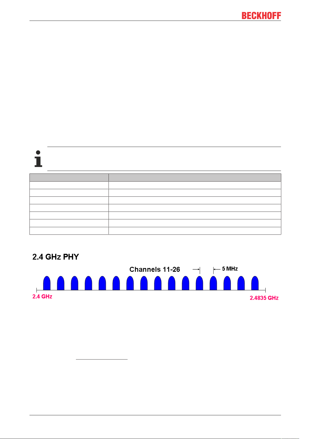
Technical data KM6551
Data transmission band 2.4GHz
Channels 16
Channel separation 5MHz
Channel width 2MHz
Available Worldwide
Data transfer rate 250kbit
Protocol IEEE802.15.4
16 channels, each with a gross data rate of 250kB/s, are available in the worldwide available 2.4GHz band.
Fig.8: Channels 11 to 26
[1] Institute of Electrical and Electronics Engineers (Ed.): IEEE Standard for Information technology -Telecommunication and information exchange between systems -- Local and metropolitan area networks -Specific requirements. Part 15.4: Wireless Medium Access Control (MAC) and Physical Layer (PHY)
Specifications for Low-Rate Wireless Personal Area Networks (LR-WPANs).IEEE Computer Society, New
York, NY, USA, October 2003
[2] ZigBee Alliance, http://www.zigbee.org
KM655114 Version: 2.0.0
Page 15
IEEE802.15.4
3.2 Interference caused by other radio systems
Check frequency ranges
• WLAN networks on adjacent or the same channels
• Microwave ovens
WLAN
If the IEEE802.15.4 channel used by the KM6551-0000 and the frequency range of a neighboring WLAN
network overlap, this can lead to disruptions in the KM6551-0000 communication.
Select an IEEE802.15.4 channel for the KM6551-0000 that uses the gaps between neighboring WLAN
networks as shown in the figure below.
Even if the maximum possible three non-overlapping WLAN channels are used adjacently, four
IEEE802.15.4 channels remain that the KM6551-0000 can use without interference.
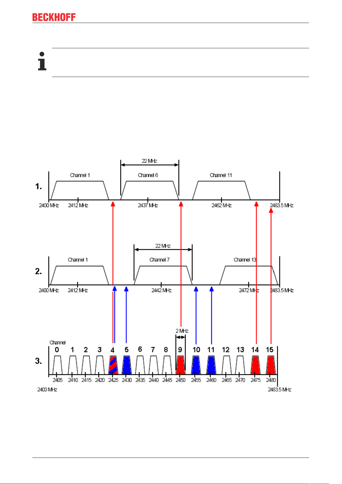
Fig.9: Utilizing gaps between adjacent WLAN networks
1. Three non-overlapping WLAN networks in the WLAN channels permitted in North America (IEEE
802.11b)
2. Three non-overlapping WLAN networks in the WLAN channels permitted in Europe (IEEE 802.11b)
3. Placement of EEE802.15.4 channels (2400MHz PHY) in the gaps between WLAN networks
KM6551 15Version: 2.0.0
Page 16

IEEE802.15.4
Microwave ovens
Since microwave ovens typically operate at a frequency of 2.455GHz, neighboring poorly screened ovens
can interfere with the transmission between the KM6551-0000.
In this case, remove the interfering devices or use only well-screened microwave ovens in the direct vicinity
of the KM6551-0000.
KM655116 Version: 2.0.0
Page 17
Mounting and wiring
4 Mounting and wiring
4.1 Recommended mounting rails
Terminal Modules und EtherCAT Modules of KMxxxx and EMxxxx series, same as the terminals of the
EL66xx and EL67xx series can be snapped onto the following recommended mounting rails:
• DIN Rail TH35-7.5 with 1mm material thickness (according to EN60715)
• DIN Rail TH35-15 with 1,5mm material thickness
Pay attention to the material thickness of the DIN Rail
Terminal Modules und EtherCAT Modules of KMxxxx and EMxxxx series, same as the terminals of
the EL66xx and EL67xx seriesdoes not fit to the DIN Rail TH35-15 with 2,2 to 2,5mm material
thickness (according to EN60715)!
4.2 Mounting and demounting - terminals with traction lever unlocking
The terminal modules are fastened to the assembly surface with the aid of a 35 mm mounting rail (e.g.
mounting rail TH 35-15).
Fixing of mounting rails
The locking mechanism of the terminals and couplers extends to the profile of the mounting rail. At
the installation, the locking mechanism of the components must not come into conflict with the fixing
bolts of the mounting rail. To mount the recommended mounting rails under the terminals and couplers, you should use flat mounting connections (e.g. countersunk screws or blind rivets).
WARNING
Risk of electric shock and damage of device!
Bring the bus terminal system into a safe, powered down state before starting installation, disassembly or
wiring of the Bus Terminals!
Mounting
• Fit the mounting rail to the planned assembly location.
KM6551 17Version: 2.0.0
Page 18
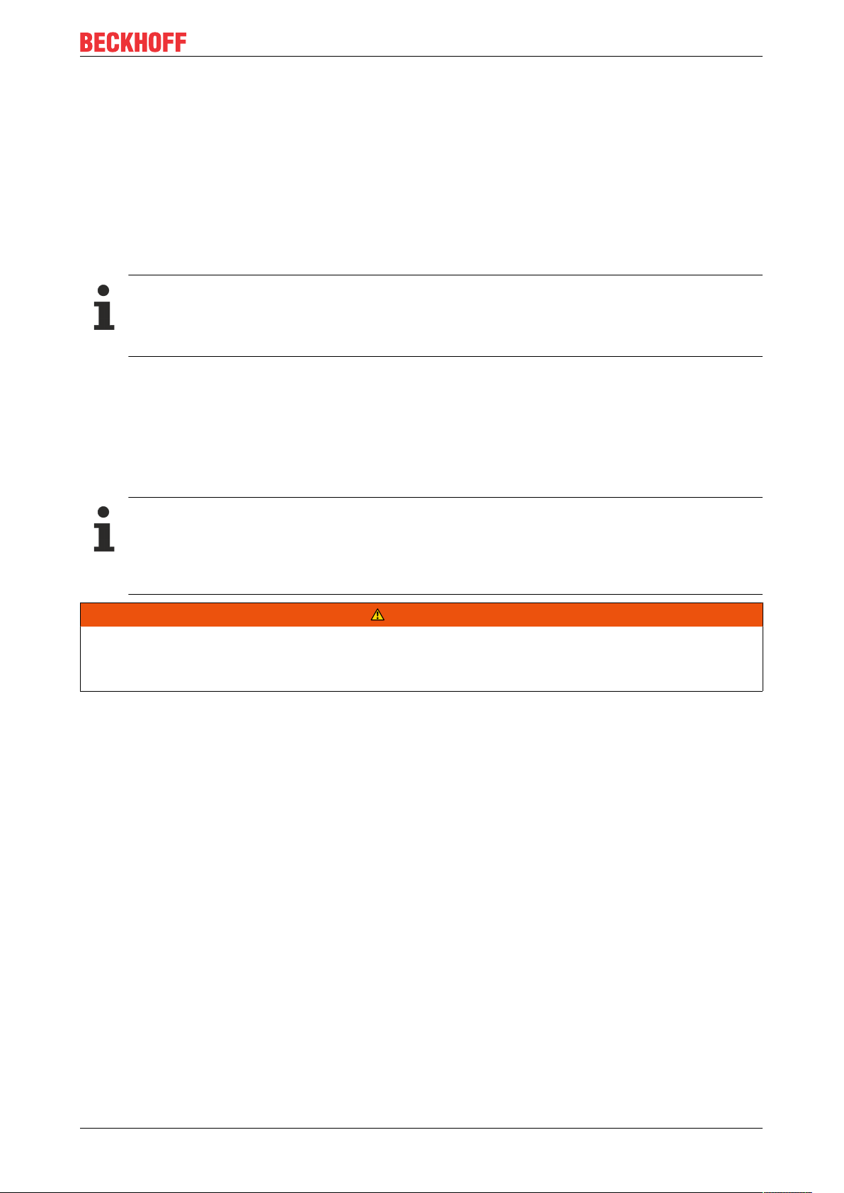
Mounting and wiring
and press (1) the terminal module against the mounting rail until it latches in place on the mounting
rail (2).
• Attach the cables.
Demounting
• Remove all the cables. Thanks to the KM/EM connector, it is not necessary to remove all the cables
separately for this, but for each KM/EM connector simply undo 2 screws so that you can pull them off
(fixed wiring)!
• Lever the unlatching hook on the left-hand side of the terminal module upwards with a screwdriver (3).
As you do this
◦ an internal mechanism pulls the two latching lugs (3a) from the top hat rail back into the terminal
module,
◦ the unlatching hook moves forwards (3b) and engages
KM655118 Version: 2.0.0
Page 19
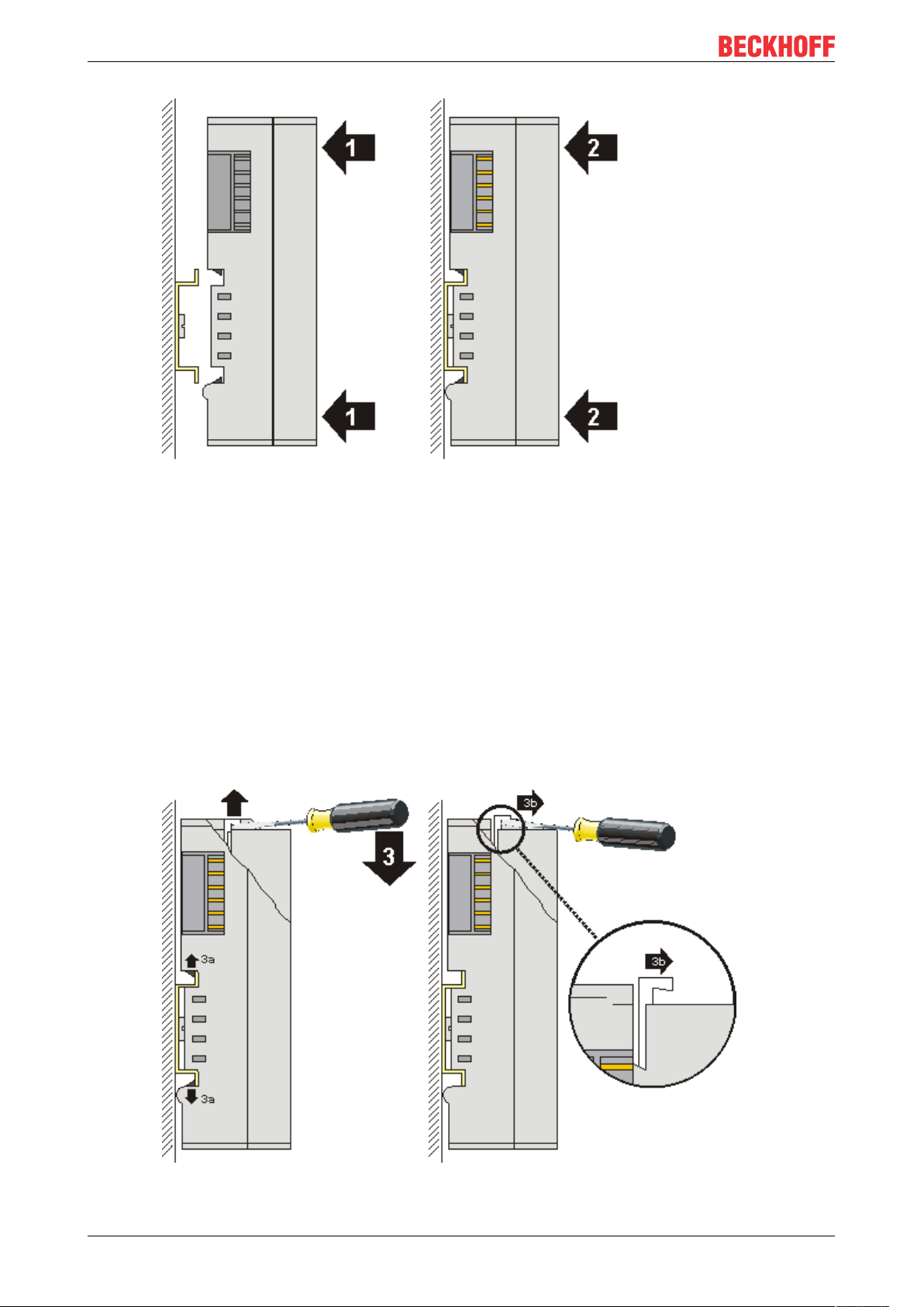
Mounting and wiring
• In the case 32 and 64 channel terminal modules (KMxxx4 and KMxxx8 or EMxxx4 and EMxxx8) you
now lever the second unlatching hook on the right-hand side of the terminal module upwards in the
same way.
• Pull (4) the terminal module away from the mounting surface.
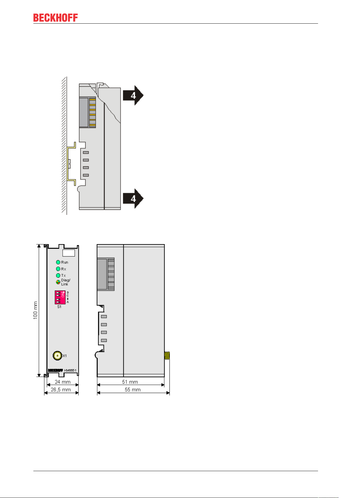
4.3 Dimensions
Fig.10: KM6551 dimensions
4.4 Connection
The antennas are connected via a reverse SMA screw plug. Please screw the cable, the coaxial cable or the
antenna hand tight to this screw plug.
KM6551 19Version: 2.0.0
Page 20

Mounting and wiring
Coaxial cable
Name Description
ZK6000-0102-0020 Coaxial cable, characteristic impedance 50Ω, preassembled plug connectors (SMA
plug and reverse SMA socket), black, 2m
ZK6000-0102-0040 Coaxial cable, characteristic impedance 50Ω, preassembled plug connectors (SMA
plug and reverse SMA socket), black, 4m
KM655120 Version: 2.0.0
Page 21
Mounting and wiring
4.5 Antenna alignment
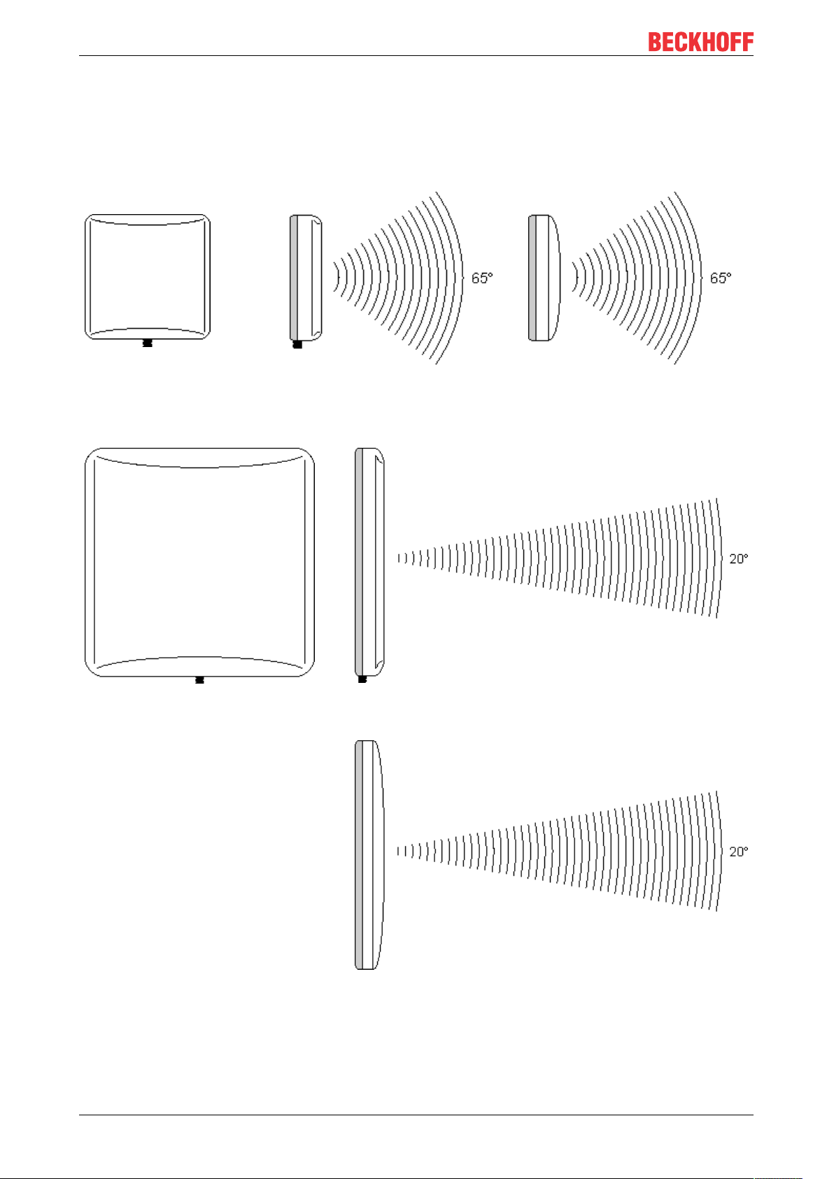
4.5.1 Directional characteristic
Please pay attention to the directional characteristics and polarization of the antennas in order to mount and
align them to each another optimally!
Omnidirectional antennas
ZS6201-0410, ZS6201-0500
Design Side view
(vertical directional characteristic)
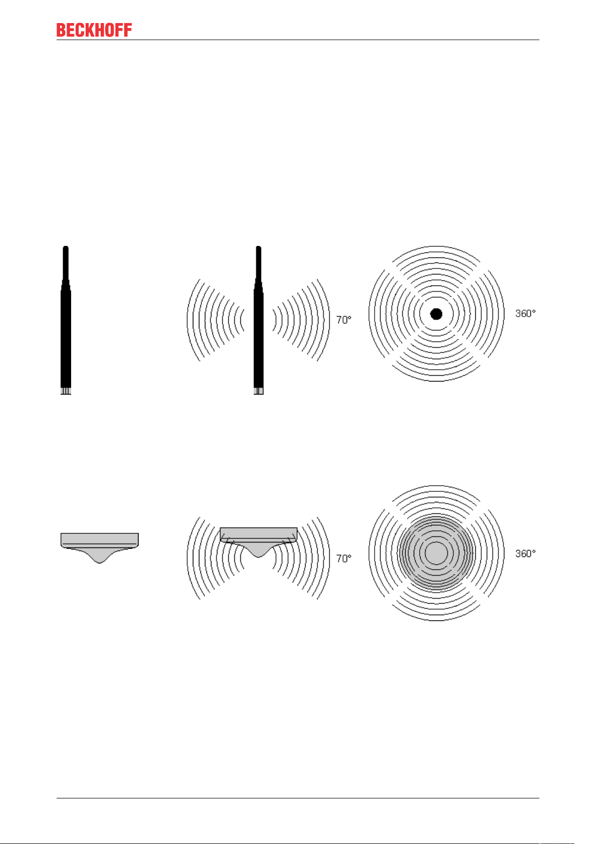
ZS6200-0400
Predestined for mounting below the ceiling.
Design Side view
(vertical directional characteristic)
Top view
(horizontal directional characteristic)
Top view
(horizontal directional characteristic)
KM6551 21Version: 2.0.0
Page 22
Mounting and wiring
Directional antennas
ZS6100-0900
Design Side view
(vertical directional characteristic)
ZS6100-1800
Design Side view (vertical directional characteristic)
Top view
(horizontal directional characteristic)
Top view (horizontal directional characteristic)
KM655122 Version: 2.0.0
Page 23
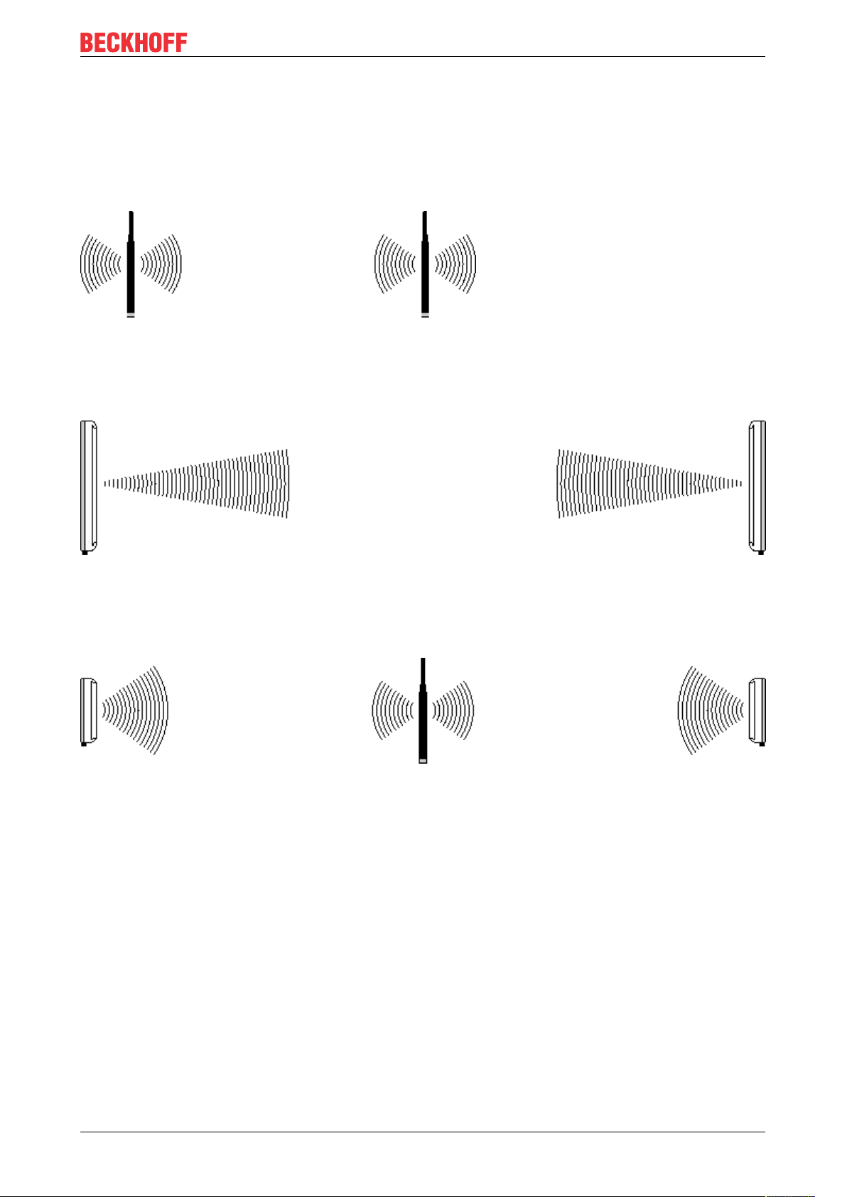
4.5.2 Alignment examples
Align the antennas so that each lies within the radiation cone of the opposite antenna.
Omnidirectional antennas
Two ZS6201-0410 or ZS6201-0500
Fig.11: Omnidirectional antennas
Directional antennas
Two ZS6100-0900 or ZS6100-1800
Mounting and wiring
Fig.12: Directional antennas
Mixed operation
e.g. one ZS6201-0410 and two ZS6100-1800
Fig.13: Mixed operation
4.5.3 Polarization
For optimum transmission, the antennas of all of the KM6551-0000 used must have the same polarization.
Omnidirectional antennas
Care must also be taken when using omnidirectional antennas that the antennas of all of the KM6551-0000
used have the same polarization.
Omnidirectional antennas such as the ZS6201-0410, ZS6201-0500 or ZS6200-0400 are mostly mounted for
vertical polarization.
Directional antennas
Arrows marked with the letters H and V are located on the rear side of the housing of the ZS6100-0900
directional antenna in order to identify the polarization (ZS6100-1800 in preparation).
KM6551 23Version: 2.0.0
Page 24

Mounting and wiring
Mount the directional antennas such that the marked arrows of all the antennas used correspond to one
another.
4.5.4 Placement of the antennas
Mount the antennas such that they can radiate freely!
There must be no obstructions in the direct vicinity of the antenna that could hinder the development of the
Fresnel zone [}25]. Metal obstacles such as control cabinets, machine parts, pipelines, iron beams etc.
particularly hinder the development of the Fresnel zone!
The connection of the antennas [}27] to the KM6551-0000 via the RSMA plug and coaxial cable [}19]
enables the antenna to be mounted remotely, so that you can position the antenna optimally.
KM655124 Version: 2.0.0
Page 25

Mounting and wiring
4.6 Attenuation and range
4.6.1 Fresnel zone
In radio transmission, the space between the transmitting and receiving antennas is known as the Fresnel
zone. The Fresnel zone is a notional spheroid between the antennas.
Fig.14: Fresnel zone
The main portion of the energy is transmitted in the area of the Fresnel zone.
This zone should be free of obstructions (e.g. objects, houses, trees etc.). Metal obstacles such as control
cabinets, machine parts, pipelines, iron beams etc. particularly hinder the development of the Fresnel zone!
Each hindrance of the Fresnel zone attenuates the transmission. If the Fresnel zone is half obscured, for
example, the additional attenuation is 6dB, i.e. the field strength is reduced to half of the free field value.
Reception may then be disturbed or completely interrupted under certain circumstances.
If the Fresnel zone is free from obstructions, the propagating wave is only attenuated by the free space
attenuation.
Fig.15: Radius r of the Fresnel zone in relationship to the distance s
KM6551 25Version: 2.0.0
Page 26

Mounting and wiring
4.6.2 Attenuation in practice
With an attenuation of 6dB the range is shortened to half of the value for an unobstructed connection, with
12dB it is shortened to a quarter.
Material Attenuation Range approx. Example for an un-
obstructed range of
280m
Thin wall 2 … 5dB (free field range)/1.5 - (free field range)/2 180m … 140m
Wooden wall 5dB (free field range)/2 140m
Masonry wall 6 … 12dB (free field range)/2 - (free field range)/4 140m … 70m
Concrete wall 10 … 20dB (free field range)/4 - (free field range)/8 70m … 5m
Concrete
ceiling
20dB (free field range)/8 <35m
4.6.3 Range of different antenna combinations
The given ranges are based on an unobstructed view and adherence to the Fresnel zone.
Two omnidirectional antennas
Fig.16: Two omnidirectional antennas
Omnidirectional antenna combined with a directional antenna
Fig.17: Omnidirectional antenna combined with a directional antenna
KM655126 Version: 2.0.0
Page 27

Two directional antennas
Fig.18: Two directional antennas
Mounting and wiring
4.7 Antennas
Overview
Name Description
ZS6100-0900 [}28]
ZS6100-1800 [}30]
ZS6200-0400 [}32]
ZS6201-0410 [}34]
ZS6201-0500 [}36]
CE conformity
The CE conformity of the KM6551-0000 is only guaranteed if it is operated with original Beckhoff accessories (antennas, coaxial cable [}19])!
Directional antenna (gain 9dBi), without cable
Directional antenna (gain 18dBi), without cable
Omnidirectional antenna (gain 4dBi), without cable
Rod antenna (gain 4dBi), with cable (1m)
Rod antenna (gain 5dBi), without cable
NOTE
KM6551 27Version: 2.0.0
Page 28

Mounting and wiring
4.7.1 ZS6100-0900
Fig.19: ZS6100-0900 - Directional antenna
Fig.20: ZS6100-0900 - Azimuth and Elevation for 2400MHz
KM655128 Version: 2.0.0
Page 29

Mounting and wiring
Technical data
Technical data ZS6100-0900
Frequency range 2400...2485MHz
Transmission factor 9dBi
3dB bandwidth, horizontal 65°
3dB bandwidth, vertical 65°
Connection SMA socket
Dimensions (WxHxD) 93mmx93mmx25mm
Weight (incl. accessories and packaging) approx.190g
Permissible ambient temperature range during
operation
Permissible relative air humidity 95%, no condensation
Protection class IP20
Installation position variable
Approval CE
Mounting Bracket mounting, included in scope of supply
Suitable coaxial cable ZS6000-0102-0020, ZS6000-0102-0040
-40°C ... + 80°C
KM6551 29Version: 2.0.0
Page 30

Mounting and wiring
4.7.2 ZS6100-1800
Fig.21: ZS6100-1800 - Directional antenna with large gain
Fig.22: ZS6100-1800 - Azimuth and Elevation for 2400MHz
KM655130 Version: 2.0.0
Page 31

Mounting and wiring
Technical data
Technical data ZS6100-1800
Frequency range 2400...2485MHz
Transmission factor 18dBi
3dB bandwidth, horizontal 20°
3dB bandwidth, vertical 20°
Connection SMA socket
Dimensions (WxHxD) 360mmx360mmx30mm
Weight (incl. accessories and packaging) approx.3640g
Permissible ambient temperature range during
operation
Permissible relative air humidity 95%, no condensation
Protection class IP20
Installation position variable
Approval CE
Mounting Bracket mounting, included in scope of supply
Suitable coaxial cable ZS6000-0102-0020, ZS6000-0102-0040
-40°C ... + 80°C
KM6551 31Version: 2.0.0
Page 32

Mounting and wiring
4.7.3 ZS6200-0400
Fig.23: ZS6200-0400 - Omnidirectional antenna
Fig.24: ZS6200-0400 - Azimuth and Elevation for 2400MHz
KM655132 Version: 2.0.0
Page 33

Mounting and wiring
Technical data
Technical data ZS6200-0400
Frequency range 2400...2485MHz
Transmission factor 4dBi
3dB bandwidth, horizontal 360°
3dB bandwidth, vertical 70°
Connection SMA socket
Dimensions Height: 110mm, diameter: 45mm
Weight (incl. accessories and packaging) approx.210g
Permissible ambient temperature range during
operation
Permissible relative air humidity 95%, no condensation
Protection class IP20
Installation position variable, predestined for mounting below the ceiling.
Approval CE
Suitable coaxial cable ZS6000-0102-0020, ZS6000-0102-0040
-40°C ... + 80°C
KM6551 33Version: 2.0.0
Page 34

Mounting and wiring
4.7.4 ZS6201-0410
Fig.25: ZS6201-0410 - Rod antenna with cable
Fig.26: ZS6201-0410 - Azimuth and Elevation for 2400MHz
KM655134 Version: 2.0.0
Page 35

Mounting and wiring
Technical data
Technical data ZS6201-0410
Frequency range 2400...2485MHz
Transmission factor 4dBi
3dB bandwidth, horizontal 360°
3dB bandwidth, vertical 70°
Connection Reverse SMA socket (with 1 m cable, permanently
connected to antenna)
Dimensions Height 202mm, foot diameter 35mm
Weight (incl. cable, accessories and packaging) approx.220g
Permissible ambient temperature range during
operation
Permissible relative air humidity 95%, no condensation
Mounting Cap nut M14
Protection class IP20
Installation position variable
Approval CE
Coaxial cable 1m, included in scope of supply
-40°C ... + 80°C
KM6551 35Version: 2.0.0
Page 36

Mounting and wiring
4.7.5 ZS6201-0500
Fig.27: ZS6201-0500 - Rod antenna
Fig.28: ZS6201-0500 - Azimuth and Elevation for 2400MHz
KM655136 Version: 2.0.0
Page 37

Mounting and wiring
Technical data
Technical data ZS6201-0500
Frequency range 2400...2485MHz
Transmission factor 5dBi
3dB bandwidth, horizontal 360°
3dB bandwidth, vertical 70°
Connection Reverse SMA socket
Dimensions Height 195mm, foot diameter 12mm
Weight (incl. packaging) approx.40g
Permissible ambient temperature range during
operation
Permissible relative air humidity 95%, no condensation
Mounting Direct connection with hinged joint
Protection class IP20
Installation position variable
Approval CE
Suitable coaxial cable Not required, direct connection
-40°C ... + 80°C
KM6551 37Version: 2.0.0
Page 38

Application examples - overview
5 Application examples - overview
• Peer to peer mode [}38]
• Master-Slave mode [}38]
• Broadcast mode [}39]
• Energy scan [}40]
5.1 Peer to peer mode
Application
The simplest type of communication between two KM6551-0000 is the peer to peer mode. To do this, set the
DIP switches [}13]
• of the master module to master mode and
• that of the second module to slave address 1.
Now you have to set bit 0 (start bit) in the control byte CB1 [}59] of both modules to TRUE. The modules
acknowledge this bit by setting bit0 of their status bytes SB1 [}59]. The establishment of communication
and the communication itself then begin automatically.
Now 10bytes are always exchanged between the modules. This continues until a start bit is reset to FALSE.
It does not matter which side resets the start bit.
If the connection is disturbed or if the start bit is not set on the opposite side, the module reports an error with
bit 6 in the status byte SB1 [}59]. The error code is output at the same time in status byte SB2 [}59] (see
ErrorID).
5.2 Master-Slave mode
Application
A further possibility is the exchange of data between a master and up to 7 slaves. The address of the slave
is set accordingly with the DIP switch [}13]. The address may only be used once for each channel. Here too
the control byte1 CB1 [}59] must be set to TRUE as bit 0 "Start BIT". Bits 3...5 are used to set the slave
address of the target device. The terminal then sends telegrams to the corresponding slave. If the terminal
receives a response, this is displayed in the status.
Example: Task – you want to speak to slave 2.
Set bit0 to TRUE in order to start data exchange. Bit3 must then be set in order to speak to slave 2. As
soon as the reply from slave 2 is received (after approx. 20ms), the master terminal confirms this in the
status byte by setting bit 4. The address is always counted +1 in the status byte (see table).
CB1 [}59]
Bit CB1.7 CB1.6 CB1.5 CB1.4 CB1.3 CB1.2 CB1.1 CB1.0
Name RegAccess reserve Add3 Add2 Add1 Scan EnergyScan Start
Value 0 0 0 0 1 0 0 1
SB1 [}59]
Bit SB1.7 SB1.6 SB1.5 SB1.4 SB1.3 SB1.2 SB1.1 SB1.0
Name RegAccess Error Add3 Add2 Add1 Scan EnergyScan Start
Value 0 0 0 1 0 0 0 1
KM655138 Version: 2.0.0
Page 39

Application examples - overview
Address Control byte bit 3...5 Status byte bit 3...5
Slave 1 0
Slave 2 1
Slave 3 2
Slave 4 3
Slave 5 4
Slave 6 5
Slave 7 6
dec
dec
dec
dec
dec
dec
dec
000
001
010
011
100
101
110
bin
bin
bin
bin
bin
bin
bin
1
dec
2
dec
3
dec
4
dec
5
dec
6
dec
7
dec
001
010
011
100
101
110
111
bin
bin
bin
bin
bin
bin
bin
Hence, you can now poll the terminals at any desired speed and in any desired rhythm. If you only send data
very rarely to a slave, remember that the watchdog in the slave terminal can trigger. The watchdog time in
the slave is approx. 400ms and can be set in register R38 [}64]. The default value is 20 and must be
multiplied by 20ms.
If a slave does not answer, then either the radio connection is disturbed or bit 0 of the control byte on the
slave side is not set; the master terminal sets the error bit 6. The error code is contained in the high nibble in
SB2.
If you want to address a new slave, make sure that the data bytes 0...9 are updated on the new slave at the
same time. When the slave replies, you should only accept the data from the new slave if the new slave
address appears in the status and the error bit is not set.
5.3 Broadcast mode
Application
Broadcast mode enables data to be sent from a master to any number of slaves. Data is thereby sent to the
slaves. The slaves receive the data, but the master does not receive any reply from the slaves.
For broadcast mode, the master must be set to master operation with the aid of the DIP switch [}13] and
register 39 [}64] must be set to broadcast mode before setting data communication. It is sufficient for the
slave to be set to broadcast-slave mode via the DIP switch.
The sequence for setting the master module to broadcast-master mode is as follows:
1. Remove the write protection R31 [}63]
2. Write broadcast master mode to R39 [}64]
3. Read out R39 [}64]to check that master mode has really been set
4. Set the start bit in CB1 [}59]
Example: Task – start the data exchange (same for master and slave)
Set bit 0 to TRUE in order to start data exchange.
CB1 [}59]
Bit CB1.7 CB1.6 CB1.5 CB1.4 CB1.3 CB1.2 CB1.1 CB1.0
Name RegAccess reserve Add3 Add2 Add1 Scan EnergyScan Start
Value 0 0 0 0 0 0 0 1
SB1 [}59]
Bit SB1.7 SB1.6 SB1.5 SB1.4 SB1.3 SB1.2 SB1.1 SB1.0
Name RegAccess Error Add3 Add2 Add1 Scan EnergyScan Start
Value 0 0 0 0 0 0 0 1
KM6551 39Version: 2.0.0
Page 40

Application examples - overview
5.4 Energy scan
Application
The energy scan enables the 16 IEEE802.15.4 channels to be monitored in order to detect other radio
systems. The energy in a frequency band is determined and displayed. Each channel is measured for
approx. 5seconds before moving to the next channel. Care must be taken that a channel does not
communicate during these 5seconds. It therefore makes sense to repeat the scanning of the channels a
couple of times in order to obtain a more accurate statement as to whether or not a channel is occupied. The
energy level is displayed through 0...0xF; "0" means no energy, "0xF" or 16dec stands for high energy level.
Set bit 1 in CB1 to TRUE. The KM6551-0000 confirms this in the status with bit1, which is then also set to
TRUE. The scan is finished when bit 1 of SB1 goes to FALSE. The result is then available in the input data
byte 0 to 7. Each channel then corresponds to a nibble, i.e. half of a byte.
Example
Byte number Description Value
(hex)
1 SB1 - Status byte 1
2 SB2 - Status byte 2
3 Data IN[0] 0x3F 3 - channel 1 low energy, F - channel 2 very high energy
4 Data IN[1] 0x01 0 - channel 3 no energy, 1 - channel 4 very low energy
5 Data IN[2] 0x7F 7 - channel 5 moderate energy, F - channel 5 very high energy
6...9 ... ... ... (not considered in this example for reasons of simplicity)
10 Data IN[8] 0x10 1 - channel 15 low energy, 0 - channel 16 no energy
11...12 Data IN[8...9] - not required
The result is to be interpreted as follows. Channels 2 and 5 are to be avoided at all costs, but channels 3 and
16 look very good. No energy was measured here. Please note that these are instantaneous values. You
can exclude channels with a high energy from further searches for free channels, but channels with no or
only moderate energy may lead under certain circumstances to entirely different results.
Example: activation of the energy scan
Set bit 1 to TRUE in order to start data exchange.
CB1 [}59]
Bit CB1.7 CB1.6 CB1.5 CB1.4 CB1.3 CB1.2 CB1.1 CB1.0
Name RegAccess reserve Add3 Add2 Add1 Scan EnergyScan Start
Value 0 0 0 0 0 0 1 0
Meaning
The terminal sets bit 1 of the status byte SB1 to TRUE as long as the scan is active.
SB1 [}59]
Bit SB1.7 SB1.6 SB1.5 SB1.4 SB1.3 SB1.2 SB1.1 SB1.0
Name RegAccess Error Add3 Add2 Add1 Scan EnergyScan Start
Value 0 0 0 0 0 0 1 0
The terminal resets bit 1 of the status byte SB1 to FALSE once the scan is finished. You can now evaluate
the input data bytes 0...7 (bytes 8-9 have no meaning and should not be evaluated).
The scan takes approx. 80 seconds.
KM655140 Version: 2.0.0
Page 41

Application examples - overview
SB1 [}59]
Bit SB1.7 SB1.6 SB1.5 SB1.4 SB1.3 SB1.2 SB1.1 SB1.0
Name RegAccess Error Add3 Add2 Add1 Scan EnergyScan Start
Value 0 0 0 0 0 0 0 0
KM6551 41Version: 2.0.0
Page 42

TwinCAT
6 TwinCAT
PLC and Motion Control on the PC
TwinCAT - The Windows Control and Automation Technology
The TwinCAT automation software converts any compatible PC into a real-time controller with multi-PLC, NC
axis control, programming environment and operating station. TwinCAT replaces conventional PLC and NC
controllers as well as operating devices:
• open, compatible PC hardware
• Embedding of IEC 61131-3 software PLC, software NC and software CNC in Windows NT/2000/XP,
NT/XP Embedded, CE
• Programming and runtime systems optionally together on one PC or separated
• Connection to all common fieldbus systems
• PC interfaces are supported
• Data communication with user interfaces and other programs by means of open Microsoft standards
(OPC, OCX, DLL, etc.)
TwinCAT architecture
TwinCAT consists of runtime systems for real-time execution of control programs and development
environments for programming, diagnosis and configuration. Any Windows programs, for instance
visualization programs or Office programs, can access TwinCAT data via Microsoft interfaces, or can
execute commands.
A practically oriented software solution
TwinCAT offers a precise time-base in which programs are executed with the highest deterministic features,
independently of other processor tasks. The real-time load on a PC is set with TwinCAT: This achieves a
defined operating behavior. TwinCAT displays the system load for running programs. A loading threshold
can be set, in order to assure a defined computing capacity for the operating programs and for Windows
NT/2000/XP. If this threshold is exceeded, a system message is generated.
TwinCAT supports system diagnosis
The general use of hardware and software from the open PC world requires some checking: Unsuitable
components can upset the PC system. Beckhoff integrates a handy display of the real-time jitter in order to
provide administrators with a simple means of evaluating hardware and software. A system message during
operation can draw attention to error states.
KM655142 Version: 2.0.0
Page 43

TwinCAT
Start/stop behavior
Depending on the setting, TwinCAT is started and stopped manually or automatically. Since TwinCAT is
integrated into Windows NT/2000/XP as a service, an operator is not needed to start the system: switching
on is enough.
Restarting and data backup
When a program is started or restarted, TwinCAT loads programs and remanent data. To backup data, and
to shut down Windows NT/2000/XP correctly, a UPS (uninterruptible power supply) is of great value.
TwinCAT and "Blue Screen"
The TwinCAT system can be configured such that real-time capability is maintained in the event of a BSOD
(Blue-Screen-of-Death) operating system crash. Real-time tasks such as PLC and NC can thus continue to
run and place the controlled process in a safe state. Ultimately, it is the decision of the programmer whether
or not to utilize this feature, bearing in mind that data or programs may already have been destroyed by the
BSOD.
World-wide connection through message routing - "remote" connection is inherent to the system
According to the requirement for operating resources, the TwinCAT software devices can be distributed:
TwinCAT PLC programs can be executed on PCs and on Beckhoff Bus Terminal controllers. A "message
router" manages and distributes all the messages, both in the system and via TCP/IP connections. PC
systems can be connected to one another by TCP/IP; Bus Terminal controllers are connected via serial
interfaces and fieldbus systems (EtherCAT, Lightbus, PROFIBUS DP, PROFINET, Interbus, CANopen,
DeviceNet, RS232, RS485, Ethernet TCP/IP, Ethernet/IP).
World-wide access
Since standard TCP/IP services from Windows NT/2000/XP are used, this data exchange can take place
worldwide. The system offers scalable communication capacity and timeout periods for the monitoring of
communications. OPC provides a standardized means for accessing many different SCADA packets. The
SOAP (Simple Object Access Protocol) enables a connection between two computers to be established by
means of an internet connection via standard HTTP. A TwinCAT component is available for this purpose.
Beckhoff Information System
Further information on the TwinCAT automation software can be found in the Beckhoff Information System.
The setup for installing the Beckhoff Information System is available to you on the Beckhoff
Products&Solutions DVD and on our website for download.
In addition, the online version of the Beckhoff Information System can be found at https://
infosys.beckhoff.com.
KM6551 43Version: 2.0.0
Page 44

TwinCAT
6.1 TwinCAT libraries
A TwinCAT library is available for all Beckhoff controller families (BC, BX, CX and IPC) for the operation of
the KM6551-0000 under TwinCAT. This library takes care of communication with the terminal. It sets
parameters in or reads parameters from the terminal. The use of the library simplifies communication with
the terminal for the user.
ZIP file TC_KM6551.zip: https://infosys.beckhoff.com/content/1033/km6551/Resources/
zip/9305592971.zip
Copy the libraries into the TwinCAT\PLC\Lib directory.
Other required libraries:
For Bus Terminal Controllers from the BCxx00 series
• Standard.lb6
• PlcHelper.lb6
For Bus Terminal Controllers from the BCxx20 and BCxx50 series
• Standard.lbx
• TcBaseBCxx50.lbx
• TcSystemBCxx50.lbx
For Bus Terminal Controllers from the BXxxxx series
• Standard.lbx
• TcBaseBX.lbx
• TcSystemBX.lbx
For 386-based systems such as Industrial PCs, Embedded PCs (CX)
• Standard.lib
• TcBase.lib
• TcSystem.lib
The user can write his own function blocks for the operation of the KM6551-0000 under other controllers.
6.2 TwinCAT examples
For the examples you need one CX9000 with K-bus, one BC9050, two KM6551-0000, two KL9010 end
terminals and one KL2xx4 (optional).
Example for master/slave communication (https://infosys.beckhoff.com/content/1033/km6551/Resources/
zip/9305595147.zip)
A KM6551-0000 is plugged into the CX9000 as a master module and optionally the KL2xx4 Bus Terminal. A
KM6551-0000 is plugged into the BC9050 as a slave module.
Example for broadcast communication (https://infosys.beckhoff.com/content/1033/km6551/Resources/
zip/9305597323.zip)
A KM6551-0000 is plugged into the CX9000 as a master module and optionally the KL2xx4 Bus Terminal. A
KM6551-0000 is plugged into the BC9050 as a broadcast slave module.
Example for energy scan (https://infosys.beckhoff.com/content/1033/km6551/Resources/
prx/9305599499.prx)
One BX9000, one KL6551-0000 and one KL9010 are required.
KM655144 Version: 2.0.0
Page 45

TwinCAT
6.3 Function blocks
6.3.1 Function block FB_KM6551_MAIN
This function block takes care of communication to the KM6651-0000 and takes care of and makes settings
in the module by means of register communication. Only one FB_KM6551_MAIN function block is permitted
per KM6551-0000.
Fig.29: Function block FB_KM6551_MAIN
VAR_INPUT
bActivate
:BOOL;
bBroadcast
:BOOL;
iChannel_Set
:INT;
uiSlaveTM
:UINT;
KM6551_IN
:ARRAY[1..12]ofBYTE;
KM6551_OUT
:ARRAY[1..12]ofBYTE;
Key
bActivate: Positive edge activates the function block and writes parameters to the KM6551-0000.
bBroadcast: Can only be activated in master mode. TRUE – sets the KM6651-0000 to broadcast master
mode (see register 39 [}64]).
iChannel_Set: The IEEE802.15.4 channel is set here. Permitted values 0..15 (see register 32/33 [}63]).
uiSlaveTM: Only usable in slave mode; setting of the watchdog for the slave mode (see register 38 [}64]).
KM6551_IN: Is connected to the INPUT data of the KM6551-0000.
KM6551_OUT: Is connected to the OUTPUT data of the KM6551-0000.
VAR_OUTPUT
bActive
:BOOL;
bError
:BOOL;
iErrorID
:E_KM6551_ERRORID;
bBusy
:BOOL;
strLinkData:KM6551_Data;
Key
b Active: The function block has successfully transmitted the parameters to KM6551-0000 and can now
commence data communication with the other KM6551-0000 function blocks.
bError: The function block has an error.
iErrorID: Contains the error code.
bBusy: The function block is still working as long as bBusy is set, i.e. is TRUE; wait until bBusy changes to
KM6551 45Version: 2.0.0
Page 46

TwinCAT
FALSE.
strLinkData: Data required by the higher-level function blocks. Connect this data to the additional function
blocks that they call.
6.3.2 Energy scan
Application
The energy scan enables the 16 IEEE802.15.4 channels to be monitored in order to detect other radio
systems. The energy in a frequency band is determined and displayed. Each channel is measured for
approx. 5seconds before moving to the next channel. Care must be taken that a channel does not
communicate during these 5seconds. It therefore makes sense to repeat the scanning of the channels a
couple of times in order to obtain a more accurate statement as to whether or not a channel is occupied. The
energy level is displayed through 0...0xF; "0" means no energy, "0xF" or 16dec stands for high energy level.
Set bit 1 in CB1 to TRUE. The KM6551-0000 confirms this in the status with bit 1, which is then also set to
TRUE. The scan is finished when bit 1 of SB1 goes to FALSE. The result is then available in the input data
byte 0 to 7. Each channel then corresponds to a nibble, i.e. half of a byte.
Example
Byte number Description Value
(hex)
1 SB1 - Status byte 1
2 SB2 - Status byte 2
3 Data IN[0] 0x3F 3 - channel 1 low energy, F - channel 2 very high energy
4 Data IN[1] 0x01 0 - channel 3 no energy, 1 - channel 4 very low energy
5 Data IN[2] 0x7F 7 - channel 5 moderate energy, F - channel 5 very high
6...9 ... ... ... (not considered in this example for reasons of simplicity)
10 Data IN[8] 0x10 1 - channel 15 low energy, 0 - channel 16 no energy
11...12 Data IN[8...9] - not required
The result is to be interpreted as follows. Channels 2 and 5 are to be avoided at all costs, but channels 3 and
16 look very good. No energy was measured here. Please note that these are instantaneous values. You
can exclude channels with a high energy from further searches for free channels, but channels with no or
only moderate energy may lead under certain circumstances to entirely different results.
Example: activation of the energy scan
Set bit 1 to TRUE in order to start data exchange.
CB1 [}59]
Meaning
energy
Bit CB1.7 CB1.6 CB1.5 CB1.4 CB1.3 CB1.2 CB1.1 CB1.0
Name RegAccess reserve Add3 Add2 Add1 Scan EnergyScan Start
Value 0 0 0 0 0 0 1 0
The terminal sets bit 1 of the status byte SB1 to TRUE as long as the scan is active.
SB1 [}59]
Bit SB1.7 SB1.6 SB1.5 SB1.4 SB1.3 SB1.2 SB1.1 SB1.0
Name RegAccess Error Add3 Add2 Add1 Scan EnergyScan Start
Value 0 0 0 0 0 0 1 0
KM655146 Version: 2.0.0
Page 47

TwinCAT
The terminal resets bit 1 of the status byte SB1 to FALSE once the scan is finished. You can now evaluate
the input data bytes 0...7 (bytes 8-9 have no meaning and should not be evaluated).
The scan takes approx. 80seconds.
SB1 [}59]
Bit SB1.7 SB1.6 SB1.5 SB1.4 SB1.3 SB1.2 SB1.1 SB1.0
Name RegAccess Error Add3 Add2 Add1 Scan EnergyScan Start
Value 0 0 0 0 0 0 0 0
6.3.3 Master/Slave mode
6.3.3.1 Function block FB_KM6551_MASTER_10BYTE
This function block takes care of communication to the individual slaves. Only one function block can be
called per slave. A maximum of 7 slaves are allowed, for which reason a maximum of 7 function blocks of
this type may be called per master terminal. A positive edge on bStart activates communication to the slave
that is stored in the variable iSlaveAddr. bBusy goes to TRUE as long as the function block is active. If
bBusy changes to FALSE, the function block has finished. If bError is FALSE, then communication was
successful and the input data is valid. If the bError bit is TRUE, an error has occurred. A precise error cause
can be read out in iErrorID. ptData_IN is a pointer address for the input data (ADR command to determine
the pointer address) and iLenData_IN is the length of the data. The length can be determined with SIZEOF
and must not be larger than 10 bytes. The same applies to the output data. The strLinkData variable is
linked to the FB_KM6551_MAIN function block (the variable has exactly the same name). The
FB_KM6551_MAIN function block should be finished before the FB_KM6551_MASTER_10BYTE function
block is called, (see bActive in this function block).
Fig.30: Function block FB_KM6551_Master_10Byte
VAR_INPUT
bStart
:BOOL;
iSlaveAddr
:INT;
strLinkData
:KM6551_Data;
ptData_IN
:DWORD;
iLenData_IN:INT;
ptData_OUT
:DWORD;
iLenData_OUT:INT;
Key
bStart: A positive edge activates the function block.
iSlaveAddr: The address of the slave is entered here (see DIP switch on your slave module)
strLinkData: Is linked with strLinkData from FB_KM6551_MAIN.
ptData_IN: Pointer to the variable into which the device data should be copied (pointer address is
KM6551 47Version: 2.0.0
Page 48

TwinCAT
determined with ADR(Variable_name)).
iLenData_IN: Length of the variable (the length can be determined with SIZEOF (variable_name))
ptData_OUT: Pointer to the variable into which the master terminal should transmit to the slave (pointer
address is determined with ADR(Variable_name)).
iLenData_OUT: Length of the variable (the length can be determined with SIZEOF (variable_name))
VAR_OUTPUT
bError
:BOOL;
bBusy
:BOOL;
iErrorID
:E_KM6551_ERRORID;
iSignalQuality:INT;
E_Addr
:E_KM6551_DIP;
Key
b Error: The function block has an error.
bBusy: The function block is still working as long as bBusy is set, i.e. is TRUE; wait until bBusy changes to
FALSE.
iErrorID: Contains the error code.
iSignalQuality: LQI value, quality of the signal received; 100 very good transmission, 0 very poor
transmission - the LQI value should be as high as possible and should have a minimum value of 10-20. You
can improve the LQI value by the use of better antennas or shorter cables or better alignment of the
antennas.
E_Addr: Reads out the DIP switch setting of the KM6551-0000 module and displays it.
6.3.3.2 Function block FB_KM6551_SLAVE_10BYTE
This function block takes care of communication to the slave module. Only one function block can be called
per slave. A positive edge on bStart activates communication to the slave. If bError is FALSE, then
communication was successful and the input data is valid. If the bError bit is TRUE, an error has occurred. A
precise error cause can be read out in iErrorID. ptData_IN is a pointer address for the input data (ADR
command to determine the pointer address) and iLenData_IN is the length of the data. The length can be
determined with SIZEOF and must not be larger than 10bytes. The same applies to the output data. The
strLinkData variable is linked to the FB_KM6551_MAIN function block (the variable has exactly the same
name). The FB_KM6551_MAIN function block should be finished before the FB_KM6551_SLAVE_10BYTE
function block is called, (see bActive in this function block).
Fig.31: Function block FB_KM6551_Slave_10Byte
VAR_INPUT
bStart
:BOOL;
strLinkData
:KM6551_Data;
ptData_IN
:DWORD;
iLenData_IN:INT;
KM655148 Version: 2.0.0
Page 49

TwinCAT
ptData_OT
:DWORD;
iLenData_OUT:INT;
Key
bStart: A positive edge activates the function block.
strLinkData: Is linked with strLinkData from FB_KM6551_MAIN.
ptData_IN: Pointer to the variable into which the device data should be copied (pointer address is
determined with ADR(Variable_name)).
iLenData_IN: Length of the variable (the length can be determined with SIZEOF (variable_name))
ptData_OUT: Pointer to the variable into which the master terminal should transmit to the slave (pointer
address is determined with ADR(Variable_name)).
iLenData_OUT: Length of the variable (the length can be determined with SIZEOF (variable_name))
VAR_OUTPUT
bError
:BOOL;
bBusy
:BOOL;
iErrorID
:E_KM6551_ERRORID;
iSignalQuality:INT;
E_Addr
:E_KM6551_DIP;
Key
b Error: The function block has an error.
bBusy: The function block is still working as long as bBusy is set, i.e. is TRUE; wait until bBusy changes to
FALSE.
iErrorID: Contains the error code.
iSignalQuality: LQI value, quality of the signal received; 100 very good transmission, 0 very poor
transmission - the LQI value should be as high as possible and should have a minimum value of 10-20. You
can improve the LQI value by the use of better antennas or shorter cables or better alignment of the
antennas.
E_Addr: Reads out the DIP switch setting of the KM6651-0000 module and displays it.
6.3.4 Broadcast mode
6.3.4.1 Function block FB_KM6551_MASTERBROADCAST_10BYTE
This function block takes care of communication to the individual slaves in broadcast mode. The number of
data telegrams can be reduced with the time tPolling. Data will then only be sent within the time tPolling. If
the tPolling time is high for the broadcast slaves, make sure that you also enter a higher watchdog time, as
otherwise the slave will display a watchdog error. A positive edge on bStart activates communication. If the
bError bit is TRUE, an error has occurred. A precise error cause can be read out in iErrorID. ptData_OUT is
a pointer address for the input data (ADR command to determine the pointer address) and iLenData_OUT is
the length of the data. The length can be determined with SIZEOF and must not be larger than 10 bytes. The
strLinkData variable is linked to the FB_KM6551_MAIN function block (the variable has exactly the same
name). The FB_KM6551_MAIN function block should be finished before the
FB_KM6551_MASTER_10BYTE function block is called, (see bActive in this function block).
KM6551 49Version: 2.0.0
Page 50

TwinCAT
Fig.32: Function block FB_KM6551_Masterbroadcast_10Byte
VAR_INPUT
bStart
:BOOL;
iSlaveAddr
:INT;
strLinkData
:KM6551_Data;
ptData_OUT
:DWORD;
iLenData_OUT:INT;
tPolling
:TIME;
Key
bStart: A positive edge activates the function block.
iSlaveAddr: The address of the slave is entered here (see DIP switch on your slave module)
strLinkData: Is linked with strLinkData from FB_KM6551_MAIN.
ptData_OUT: Pointer to the variable into which the master terminal should transmit to the slave (pointer
address is determined with ADR(Variable_name)).
iLenData_OUT: Length of the variable (the length can be determined with SIZEOF (variable_name))
tPolling: Time cycle in which the data should be sent to the slaves.
VAR_OUTPUT
bError
:BOOL;
bActive
:BOOL;
iErrorID
:E_KM6551_ERRORID;
E_Addr
:E_KM6551_DIP;
Key
b Error: The function block has an error.
bActive: Indicates whether or not the function block is working.
iErrorID: Contains the error code.
E_Addr: Reads out the DIP switch setting of the KM6551-0000 and displays it.
6.3.4.2 Function block FB_KM6551_SLAVEBROADCAST_10BYTE
This function block takes care of communication to the broadcast slave module. Only one function block can
be called per slave. A positive edge on bStart activates communication to the slave. If bError is FALSE, then
communication was successful and the input data is valid. If the bError bit is TRUE, an error has occurred. A
precise error cause can be read out in iErrorID. ptData_IN is a pointer address for the input data (ADR
command to determine the pointer address) and iLenData_IN is the length of the data. The length can be
determined with SIZEOF and must not be larger than 10 bytes. The same applies to the output data. The
strLinkData variable is linked to the FB_KM6551_MAIN function block (the variable has exactly the same
name). The FB_KM6551_MAIN function block should be finished before the
FB_KM6551_MASTER_10BYTE function block is called, (see bActive in this function block).
KM655150 Version: 2.0.0
Page 51

Fig.33: Function block FB_KM6551_Slavebroadcast_10Byte
VAR_INPUT
bStart
:BOOL;
strLinkData
:KM6551_Data;
ptData_IN
:DWORD;
iLenData_IN:INT;
Key
bStart: A positive edge activates the function block.
strLinkData: Is linked with strLinkData from FB_KM6551_MAIN.
ptData_IN: Pointer to the variable into which the device data should be copied (pointer address is
determined with ADR(Variable_name)).
iLenData_IN: Length of the variable (the length can be determined with SIZEOF (variable_name))
TwinCAT
VAR_OUTPUT
bError
:BOOL;
bActive
:BOOL;
iErrorID
:E_KM6551_ERRORID;
iSignalQuality:INT;
E_Addr
:E_KM6551_DIP;
Key
b Error: The function block has an error.
bActive: Indicates whether or not the function block is working.
iErrorID: Contains the error code.
iSignalQuality: LQI value, quality of the signal received; 100 very good transmission, 0 very poor
transmission - the LQI value should be as high as possible and should have a minimum value of 10-20. You
can improve the LQI value by the use of better antennas or shorter cables or better alignment of the
antennas.
E_Addr: Reads out the DIP switch setting of the KM6651-0000 module and displays it.
KM6551 51Version: 2.0.0
Page 52

KS2000 Configuration Software
7 KS2000 Configuration Software
7.1 KS2000 - Introduction
The KS2000 configuration software permits configuration, commissioning and parameterization of bus
couplers, of the affiliated bus terminals and of Fieldbus Box Modules. The connection between bus coupler/
Fieldbus Box Module and the PC is established by means of the serial configuration cable or the fieldbus.
Fig.34: KS2000 configuration software
Configuration
You can configure the Fieldbus stations with the Configuration Software KS2000 offline. That means, setting
up a terminal station with all settings on the couplers and terminals resp. the Fieldbus Box Modules can be
prepared before the commissioning phase. Later on, this configuration can be transferred to the terminal
station in the commissioning phase by means of a download. For documentation purposes, you are provided
with the breakdown of the terminal station, a parts list of modules used and a list of the parameters you have
modified. After an upload, existing fieldbus stations are at your disposal for further editing.
Parameterization
KS2000 offers simple access to the parameters of a fieldbus station: specific high-level dialogs are available
for all bus couplers, all intelligent bus terminals and Fieldbus Box modules with the aid of which settings can
be modified easily. Alternatively, you have full access to all internal registers of the bus couplers and
intelligent terminals. Refer to the register description for the meanings of the registers.
KM655152 Version: 2.0.0
Page 53

KS2000 Configuration Software
Commissioning
The KS2000 software facilitates commissioning of machine components or their fieldbus stations: Configured
settings can be transferred to the fieldbus modules by means of a download. After a login to the terminal
station, it is possible to define settings in couplers, terminals and Fieldbus Box modules directly online. The
same high-level dialogs and register access are available for this purpose as in the configuration phase.
The KS2000 offers access to the process images of the bus couplers and Fieldbus Box modules.
• Thus, the coupler's input and output images can be observed by monitoring.
• Process values can be specified in the output image for commissioning of the output modules.
All possibilities in the online mode can be used in parallel with the actual fieldbus mode of the terminal
station. The fieldbus protocol always has the higher priority in this case.
7.2 Parameterization with KS2000
Connect the configuration interface of your Fieldbus Coupler with the serial interface of your PC via the
configuration cable and start the KS2000 Configuration Software.
Click on the Login button. The configuration software will now load the information
for the connected fieldbus station.
In the example shown, this is
• a BK9000 Bus Coupler for Ethernet
• a KL1002 input terminal
• a KM6551-0000 data exchange terminal
• a KL9010 Bus End Terminal
KM6551 53Version: 2.0.0
Page 54

KS2000 Configuration Software
Fig.35: Display of the fieldbus station in KS2000
The left-hand KS2000 window displays the terminals of the fieldbus station in a tree structure.
The right-hand KS2000window contains a graphic display of the fieldbus station terminals.
In the tree structure of the left-hand window, click on the plus-sign next to the module whose parameters you
wish to change (pos. 2 in the example).
Fig.36: KS2000 branch for channel 1 of the KM6551
The tree branches Register, Settings and ProcData are displayed for the KM6551-0000:
• Register [}56] allows direct access to the registers of the KM6551-0000.
• Under settings [}55] you will find dialog masks for parameterizing the KM6551-0000.
• Process data [}57] shows the process data of the KM6551-0000.
KM655154 Version: 2.0.0
Page 55

7.3 Settings
Dialog screen for parameterizing the KM6551.
Fig.37: Dialog screen for parameterizing the KM6551
KS2000 Configuration Software
Settings
Radio channel for KM6551 (R33)
R33 [}64]
Here you can set the radio channel. (Default: 5, permissible values: 0 to 15).
Scan settings
Found slaves
Displays the number of slaves found (R40 [}64]).
Slaves (R40)
R40 [}64]
Displays the slave numbers of the found slaves.
KM6551 55Version: 2.0.0
Page 56

KS2000 Configuration Software
7.4 Register
Under Register you can directly access the registers of the KM6551-0000 terminal module. The meaning of
the register is explained in the Register overview [}62].
Fig.38: Register view in KS2000
KM655156 Version: 2.0.0
Page 57

KS2000 Configuration Software
7.5 Process data
The Status byte (Status), the Control byte (Ctrl) and the process data (Data) are displayed in a tree structure
under ProcData.
Fig.39: Process Data field
The spectacles mark the data that are currently graphically displayed in the History field.
Fig.40: History field
The current input value is displayed numerically in the Value field.
Fig.41: Value field
Output values can be modified through direct input or by means of the fader control.
KM6551 57Version: 2.0.0
Page 58

KS2000 Configuration Software
Fig.42: Value field
CAUTION
Danger for persons, the environment or devices!
Note that changing output values (forcing) can have a direct effect on your automation application. Only
modify these output values if you are certain that the state of your equipment permits it, and that there will
be no risk to people or to the machine!
After pressing the Settings button you can set the format of the numerical display to hexadecimal, decimal or
binary.
Fig.43: Setting the display
KM655158 Version: 2.0.0
Page 59

Access from the user program
8 Access from the user program
8.1 Process image
The KM6551-0000 terminal module represents itself in the process image with a maximum of 12bytes of
input data and 12bytes of output data. These are organized as follows:
Format Input data Output data
Byte
Byte SB2 CB2
Array of bytes (0...9) DataIN DataOUT
Key
SBn: status byte n
CBn: control byte n
DataIN: Array of 10 input bytes (0...9)
DataOUT: Array of 10 input bytes (0...9)
SB1 [}60] CB1 [}59]
The meaning of the control and status bytes is explained in Control and status bytes [}59].
In process data operation, the input data is transmitted in the DataIn array and the output data in the
DataOUT array.
Use of the data arrays
• use them, for example, to transmit the process data from analog input or output channels.
• also use the 10bytes in order to transmit larger amounts of data in several cycles using a selfdefined protocol (e.g. 2bytes for the header, 8bytes for the user data).
8.2 Control and Status Bytes
8.2.1 Process data mode
Control bytes (for process data mode)
The control bytes are located in the output image and are transmitted from the controller to the terminal
module.
CB1: Low byte
Bit CB1.7 CB1.6 CB1.5 CB1.4 CB1.3 CB1.2 CB1.1 CB1.0
Name RegAccess - Address Scan EnergyScan Start
CB2: High byte
Bit CB2.7 CB2.6 CB2.5 CB2.4 CB2.3 CB2.2 CB2.1 CB2.0
Name - - - - - - - -
KM6551 59Version: 2.0.0
Page 60

Access from the user program
Key
Bit Name Description
CB2.0 to CB2.7 reserve 0
CB1.7 RegAccess 0
CB1.6 reserve 0
bin
bin
bin
CB1.3 to CB1.5 Address 0..7
reserved
Register communication off (process data mode)
reserved
In master mode, with whichever device the connection is running
dec
0 - Slave 1
1 - Slave 2
...
6 - Slave 7
CB1.2 Scan 1
bin
Activates scanning of the connected slaves (only possible in
master mode). The scanned slaves can be found in register R38
[}64].
CB1.1 EnergyScan 1
bin
Activates the energy measurement for the 16 channels of the 2.4
GHz band. EnergyScan may not be activated in data exchange or
scan mode.
CB1.0 Start 1
bin
Activates communication
Status byte (for process data mode)
The status bytes are located in the input image and are transmitted from terminal module to the controller.
SB1: Low byte
Bit SB1.7 SB1.6 SB1.5 SB1.4 SB1.3 SB1.2 SB1.1 SB1.0
Name RegAccess Error Address Scan EnergyScan Start
SB2: High byte
Bit SB2.7 SB2.6 SB2.5 SB2.4 SB2.3 SB2.2 SB2.1 SB2.0
Name ErrorID LQI
Key
Bit Name Description
SB2.7 to SB2.4 ErrorID 0..F
Error message
hex
1 - invalid or forbidden DIP switch position
2 - watchdog error
3... F not used
SB2.3 to SB2.0 LQI 0..F
SB1.7 RegAccess 0
SB1.6 Error 1
bin
bin
Quality of the radio signal
hex
Acknowledgment for process data mode
an internal error has occurred (current process data is no longer
valid)
SB1.5 to SB1.3 Address 1..7
Slave address
dec
1: Slave 1
2: Slave 2
...
7: Slave 7
SB1.2 Scan 1
SB1.1 EnergyScan 1
bin
bin
TRUE if energy scanning is active; will be reset to FALSE when
the terminal has finished.
SB1.0 Start 1
bin
KM655160 Version: 2.0.0
Page 61

Access from the user program
8.2.2 Register communication
Control byte 2 and status byte 2 have no function in the case of register communication.
Control byte 1 (in register communication)
Control byte 1 (CB1) is located in the output image, and is transmitted from the controller to the terminal
module.
Bit CB1.7 CB1.6 CB1.5 CB1.4 CB1.3 CB1.2 CB1.1 CB1.0
Name RegAccess R/W Reg. no.
Key
Bit Name Description
CB1.7 RegAccess 1
CB1.6 R/W 0
bin
bin
1
bin
CB1.5 to CB1.0 Reg. no. Register number:
Enter here the number of the register that you wish
- to read with input data wordDataIn, or
- to write with output data word DataOut.
Register communication switched on
Read access
Write access
Status byte 1 (in register communication)
Status byte 1(SB1) is located in the input image and is transmitted from terminal module to the controller.
Bit SB1.7 SB1.6 SB1.5 SB1.4 SB1.3 SB1.2 SB1.1 SB1.0
Name RegAccess R/W Reg. no.
Key
Bit Name Description
SB1.7 RegAccess 1
SB1.6 R 0
bin
bin
Acknowledgment for register access
Read access
SB1.5 to SB1.0 Reg. no. Number of the register that was read or written.
KM6551 61Version: 2.0.0
Page 62

Access from the user program
8.3 Register overview
These registers are used to parameterize the terminal module. They can be read or written by means of the
register communication [}65].
Register no. Comment Default value R/W Memory
R0 reserved 0x0000 0
dec
... ... ... ... ... ...
R7 reserved 0x0000 0
R8 [}63]
R9 [}63]
Terminal type 0x1997 6551
Firmware version e.g. 0x3144 e.g. 1D
R10 Multiplex shift register 0x0118 280
R11 Signal channels 0x0218 280
R12 minimum data length of a channel 0x0098 152
R13 Data structure 0x0000 0
R14 reserved 0x0000 0
dec
dec
ASCI
dec
dec
dec
dec
dec
R15 Alignment register typically 0x7F80 typically
32640
dec
R16 [}63]
R17 internal use typically 0x0000 typically 0
R18 reserved 0x0000 0
R19 reserved 0x0000 0
R20 reserved for internal use 0x0001 1
R21 reserved for internal use 0x0500 1280
R22 reserved for internal use 0x0000 0
R23 reserved for internal use 0x00FF 255
R24 reserved 0x0000 0
DIP switch setting e.g.0x0000 e.g.0
dec
dec
dec
dec
dec
dec
dec
dec
dec
... ... ... ... ... ...
R30 reserved 0x0000 0
R31 [}63]
R32 [}63]
Code word register 0x0000 0
IEEE 802.15.4 channel 0x0005 5
R33 Control register for R32 0x0000 0
R34 reserved 0x0000 0
R35 reserved 0x0000 0
R36 reserved 0x0000 0
R37 reserved 0x0000 0
R38 [}64]
R39 [}64]
Watchdog for slave mode 0x0014 20
Broadcast mode 0x0000 0
dec
dec
dec
dec
dec
dec
dec
dec
dec
dec
R40 Scan register - - R RAM
R41 [}64]
Network ID 0x0000 0
dec
R42 Wrong channel (internal) - - R EEPROM
R43 reserved 0x0000 0
dec
R44 Reset counter (internal) - - R EEPROM
R45 reserved 0x0000 0
R46 [}64]
Attenuation of the transmission power 0x0000 0
R47 reserved 0x0000 0
dec
dec
dec
... ... ... ... ... ...
R63 reserved 0x0000 0
dec
- -
- -
R ROM
R ROM
R ROM
R ROM
R ROM
R ROM
- -
R/W RAM
R RAM
R EEPROM
R EEPROM
R EEPROM
R EEPROM
R EEPROM
R EEPROM
R EEPROM
- -
- -
R/W EEPROM
R/W EEPROM
R RAM
R/W EEPROM
R/W EEPROM
R/W EEPROM
R/W EEPROM
R/W EEPROM
R/W EEPROM
R/W RAM
R EEPROM
R EEPROM
R/W EEPROM
R EEPROM
R EEPROM
KM655162 Version: 2.0.0
Page 63

Access from the user program
8.4 Register description
These registers are used to parameterize the terminal module. They can be read or written by means of the
register communication [}65].
R8: Module ID
Register R8 contains the name for the terminal module.
KM6551-0000: 0x1997 (6551
R9: Firmware version
Register R9 contains the ASCII coding of the terminal's firmware version, e.g. 0x3141 = '1A'. '0x31'
corresponds to the ASCII character '1', '0x41' corresponds to the ASCII character 'A'.
This value cannot be changed.
R12: Minimum data length of a channel
dec
)
Bits 0 to 6 of the high-order byte specify the minimum number of output data in bits: 000.0000
bin
= 0
, hence
dec
0byte.
Bits 0 to 6 of the low-order byte specify the minimum number of input data in bits: 001.1000
bin
= 24
, hence
dec
3bytes.
The fact that bit7 is set indicates that the control and status byte are not mandatory for the terminal function
and are not transferred in compact mode.
R16: DIP switch setting
The DIP switch setting is stored in register R16.
Value (hex) String (ASCII) Operation Mode
0x414D MA Master
0x4253 SB Slave for broadcast reception
0x3153 S1 Slave with address 1
0x3253 S2 Slave with address 2
0x3353 S3 Slave with address 3
0x3453 S4 Slave with address 4
0x3553 S5 Slave with address 5
0x3653 S6 Slave with address 6
0x3753 S7 Slave with address 7
0xFFFF - Unknown DIP switch
R31: Code word register
• If you write values into the user registers without first entering the user code word (0x1235) into the
code word register, the terminal will not accept the supplied data.
• If you write values into the user registers and have previously entered the user code word (0x1235) in
the code word register, these values are stored in the RAM registers and in the SEEPROM registers
and are therefore retained when the terminal is restarted.
The code word is reset when the terminal is restarted.
R32: Channel register (read/write)
IEEE802.15.4 allows the use of one of 16 available channels. These frequency ranges work without
influencing one another. The bandwidth of the signal is 2MHz and the channel separation is 5MHz. The
channel should be selected such that it does not collide with WLAN or other systems that transmit in the
KM6551 63Version: 2.0.0
Page 64

Access from the user program
2.4GHz range. Permitted settings in register 0...15.
It is permitted to change the channel during operation. The terminal displays the channel change in R33. The
frequency channel has been accepted if R32 and R33 are identical.
R33: Channel register (read only)
The terminal acknowledges the acceptance of the channel in this channel. When accepting the new channel
in R32, the terminal confirms this by entering the channel in R33.
R38: Watchdog (only activated in slave mode)
The watchdog for the slave is set in register R38. If the value is 0, the watchdog is deactivated. Therefore, no
error bit will be set in the event of interrupted communication. The default value is 20
. The value from R38
dec
must be multiplied by approx. 20ms.
Example: R38 = 100 (100x20ms=2000msor2sec).
R39: Broadcast mode
Broadcast mode for the broadcast master is activated in register R39. The register is not evaluated by the
broadcast slaves. The slaves are “made into” broadcast slaves via the DIP switch.
0x0000: Master-slave- or peer to peer mode (default)
0x4342: Broadcast mode (master)
R40: Scan (only possible in master mode)
The slaves found are entered here if the scan has been activated with the bitCB1.2. Each bit represents a
found slave address.
R41: Network ID
Using the network ID you can distinguish between up to 255 radio networks. The KM6551-0000 only accepts
telegrams from modules with the same network ID.
Permissible value range: 0...255
The default value is 0
dec.
dec
.
Operation of several radio networks
If you wish to operate different radio networks within the range (e.g. inside a factory hall), distinguishing the networks by the use of different channel numbers guarantees more freedom from interference than if you operate networks with different network IDs on the same channel! Use the network ID to distinguish between different radio networks only if no more free channels are available!
R46: Attenuation of the transmission power
You can attenuate the transmission power of the KM6551-0 using bits 0000 to 7 of register R46. The setting
only takes effect when the module is restarted.
Bit 15 14 13 12 11 10 9 8
Name - - - - - - - -
Bit 7 6 5 4 3 2 1 0
Name Large Scale Small Scale - - -
KM655164 Version: 2.0.0
Page 65

Access from the user program
Key
Bit Name Description default
15...8 - reserved 00
7...6 Large Scale 11
5...3 Small Scale 111
minus 30dB 00
bin
10
minus 20dB
bin
01
minus 10dB
bin
00
minus 0.0dB
bin
minus 6.3dB 000
bi
n
110
minus 4.9dB
bi
n
101
minus 3.7dB
bi
n
100
minus 2.8dB
bi
n
011
minus 1.9dB
bi
n
010
minus 1.2dB
bi
n
001
minus 0.5dB
bi
n
000
minus 0.0dB
bi
n
2...0 - reserved 000
bin
bin
bin
bin
8.5 Examples of Register Communication
The numbering of the bytes in the examples corresponds to the display without word alignment.
8.5.1 Example 1: reading the firmware version from Register 9
Output Data
Byte 0: Control byte Byte 1: DataOUT1, high byte Byte 2: DataOUT1, low byte
0x89 (1000 1001
Explanation:
• Bit 0.7 set means: Register communication switched on.
• Bit 0.6 not set means: reading the register.
• Bits 0.5 to 0.0 specify the register number 9 with 00 1001
• The output data word (byte 1 and byte 2) has no meaning during read access. To change a register,
write the required value into the output word.
Input Data (answer of the Bus Terminal)
Byte 0: Status byte Byte 1: DataIN1, high byte Byte 2: DataIN1, low byte
0x89 0x33 0x41
) 0xXX 0xXX
bin
.
bin
Explanation:
• The terminal returns the value of the control byte as a receipt in the status byte.
KM6551 65Version: 2.0.0
Page 66

Access from the user program
• The terminal returns the firmware version 0x3341 in the input data word (byte 1 and byte 2). This is to
be interpreted as an ASCII code:
◦ ASCII code 0x33 represents the digit 3
◦ ASCII code 0x41 represents the letter A
The firmware version is thus 3A.
8.5.2 Example 2: Writing to an user register
Code word
In normal mode all user registers are read-only with the exception of Register 31. In order to deactivate this write protection you must write the code word (0x1235) into Register 31. If a value other
than 0x1235 is written into Register 31, write protection is reactivated. Please note that changes to
a register only become effective after restarting the terminal (power-off/power-on).
I. Write the code word (0x1235) into Register 31.
Output Data
Byte 0: Control byte Byte 1: DataOUT1, high byte Byte 2: DataOUT1, low byte
0xDF (1101 1111
) 0x12 0x35
bin
Explanation:
• Bit 0.7 set means: Register communication switched on.
• Bit 0.6 set means: writing to the register.
• Bits 0.5 to 0.0 specify the register number 31 with 01 1111
.
bin
• The output data word (byte 1 and byte 2) contains the code word (0x1235) for deactivating write
protection.
Input Data (answer of the Bus Terminal)
Byte 0: Status byte Byte 1: DataIN1, high byte Byte 2: DataIN1, low byte
0x9F (1001 1111
) 0xXX 0xXX
bin
Explanation:
• The terminal returns a value as a receipt in the status byte that differs only in bit 0.6 from the value of
the control byte.
• The input data word (byte 1 and byte 2) is of no importance after the write access. Any values still
displayed are invalid!
II. Read Register 31 (check the set code word)
Output Data
Byte 0: Control byte Byte 1: DataOUT1, high byte Byte 2: DataOUT1, low byte
0x9F (1001 1111
) 0xXX 0xXX
bin
Explanation:
• Bit 0.7 set means: Register communication switched on.
• Bit 0.6 not set means: reading the register.
• Bits 0.5 to 0.0 specify the register number 31 with 01 1111
.
bin
• The output data word (byte 1 and byte 2) has no meaning during read access.
KM655166 Version: 2.0.0
Page 67

Access from the user program
Input Data (answer of the Bus Terminal)
Byte 0: Status byte Byte 1: DataIN1, high byte Byte 2: DataIN1, low byte
0x9F (1001 1111
) 0x12 0x35
bin
Explanation:
• The terminal returns the value of the control byte as a receipt in the status byte.
• The terminal returns the current value of the code word register in the input data word (byte 1 and byte
2).
III. Write to Register 32 (change contents of the feature register)
Output data
Byte 0: Control byte Byte 1: DataIN1, high byte Byte 2: DataIN1, low byte
0xE0 (1110 0000
) 0x00 0x02
bin
Explanation:
• Bit 0.7 set means: Register communication switched on.
• Bit 0.6 set means: writing to the register.
• Bits 0.5 to 0.0 indicate register number 32 with 10 0000
.
bin
• The output data word (byte 1 and byte 2) contains the new value for the feature register.
CAUTION
Observe the register description!
The value of 0x0002 given here is just an example!
The bits of the feature register change the properties of the terminal and have a different meaning, depending on the type of terminal. Refer to the description of the feature register of your terminal (chapter Register
description) regarding the meaning of the individual bits before changing the values.
Input data (response from the Bus Terminal)
Byte 0: Status byte Byte 1: DataIN1, high byte Byte 2: DataIN1, low byte
0xA0 (1010 0000
Explanation:
• The terminal returns a value as a receipt in the status byte that differs only in bit 0.6 from the value of
the control byte.
• The input data word (byte 1 and byte 2) is of no importance after the write access. Any values still
displayed are invalid!
IV. Read Register 32 (check changed feature register)
Output Data
Byte 0: Control byte Byte 1: DataOUT1, high byte Byte 2: DataOUT1, low byte
0xA0 (1010 0000
) 0xXX 0xXX
bin
) 0xXX 0xXX
bin
Explanation:
• Bit 0.7 set means: Register communication switched on.
• Bit 0.6 not set means: reading the register.
• Bits 0.5 to 0.0 indicate register number 32 with 10 0000
.
bin
• The output data word (byte 1 and byte 2) has no meaning during read access.
KM6551 67Version: 2.0.0
Page 68

Access from the user program
Input Data (answer of the Bus Terminal)
Byte 0: Status byte Byte 1: DataIN1, high byte Byte 2: DataIN1, low byte
0xA0 (1010 0000
) 0x00 0x02
bin
Explanation:
• The terminal returns the value of the control byte as a receipt in the status byte.
• The terminal returns the current value of the feature register in the input data word (byte 1 and byte 2).
V. Write Register 31 (reset code word)
Output Data
Byte 0: Control byte Byte 1: DataOUT1, high byte Byte 2: DataOUT1, low byte
0xDF (1101 1111
) 0x00 0x00
bin
Explanation:
• Bit 0.7 set means: Register communication switched on.
• Bit 0.6 set means: writing to the register.
• Bits 0.5 to 0.0 specify the register number 31 with 01 1111
.
bin
• The output data word (byte 1 and byte 2) contains 0x0000 for reactivating write protection.
Input Data (answer of the Bus Terminal)
Byte 0: Status byte Byte 1: DataIN1, high byte Byte 2: DataIN1, low byte
0x9F (1001 1111
) 0xXX 0xXX
bin
Explanation:
• The terminal returns a value as a receipt in the status byte that differs only in bit 0.6 from the value of
the control byte.
• The input data word (byte 1 and byte 2) is of no importance after the write access. Any values still
displayed are invalid!
KM655168 Version: 2.0.0
Page 69

9 Appendix
9.1 General operating conditions
Approval and use
The KM6551-0000 module meets the requirements of EN 300-440-02 V1.1.2.
Operation of the KM6551-0000 module is permitted in all EU countries as well as in Switzerland and
Liechtenstein. Other countries on enquiry.
The use of the KM6551-0000 is permitted with the following antennas:
Name Description
ZS6100-0900 [}28]
ZS6100-1800 [}30]
ZS6200-0400 [}32]
ZS6201-0410 [}34]
ZS6201-0500 [}36]
Directional antenna (gain 9dBi), without cable
Directional antenna (gain 18dBi), without cable
Omnidirectional antenna (gain 4dBi), without cable
Rod antenna (gain 4dBi), with cable (1m)
Rod antenna (gain 5dBi), without cable
Appendix
NOTE
CE conformity
The CE conformity of the KM6551-0000 is only guaranteed if it is operated with original Beckhoff accessories (antennas, coaxial cable [}19])!
Environmental conditions
The following conditions must be met in order to ensure flawless operation of the fieldbus components.
Operation
The components may not be used without additional protection in the following locations:
• in difficult environments, such aswhere there are corrosive vapors or gases, or high dust levels
• in the presence of high levels of ionizing radiation
Condition Permissible range
Permissible ambient temperature during
operation
Permissible ambient temperature during
operation
Installation position variable
Vibration resistance conforms to EN60068-2-6
Shock resistance conforms to EN60068-2-27, EN60068-2-29
EMC immunity conforms to EN61000-6-2
Emission conforms to EN61000-6-4, EN300-440-02 V1.1.2
Safety of persons in electromagnetic fields conforms to EN 50371:2002
0°C...+55°C
-25°C... +85°C
KM6551 69Version: 2.0.0
Page 70

Appendix
Transport and storage
Condition Permissible range
Permissible ambient temperature during
storage
Relative humidity 95 %, no condensation
Free fall up to 1m in the original packaging
Protection classes and types
Condition Permissible range
Protection class in accordance with IEC 536
(VDE 0106, Part 1)
Protection class conforms to IEC 529 IP20 (protection against contact with a standard test finger)
Protection against foreign objects Less than 12mm in diameter
Protection against water no protection
-25°C... +85°C
A protective conductor connection to the profile rail is
necessary!
KM655170 Version: 2.0.0
Page 71

9.2 EC declaration of conformity
Appendix
Fig.44: EC declaration of conformity
KM6551 71Version: 2.0.0
Page 72

Appendix
9.3 Calculating with decibels
In communication technology power is expressed in decibels (dB), a tenth of the unit Bel. It is the logarithmic
ratio between two quantities with the same unit.
A reference variable (P1), e.g. a milliwatt (mW) is compared with the measured variable (P2). The
logarithmic correlation was discovered by Alexander Graham Bell, in whose honor the unit Bel was named.
Since the number values would be too unwieldy if the Bel was used, it was agreed to use 1/10 of the value,
i.e. the decibel.
Definition of the level difference: Level difference [dB] = 10 log ([P1] / [P2]).
Definition of a power ratio: power ratio = 10
The advantage of expressing the powers and losses (attenuations) in dB is that the calculation method for
power ratios can be replaced by a lower calculation method for the dB calculation.
Power ratio dB calculation
Multiplication or division Addition or subtraction
Exponent Factor
Examples of power ratios
level difference/10
Factor Amplification [dB]
x1 +0dB
x 1.25 +1dB
x 2 +3dB
x 4 +6dB
x 10 +10dB
x 16 +12dB
x 100 +20dB
x 1000 +30dB
Factor Attenuation [dB]
x1 -0dB
x 0.8 -1dB
x 0.5 -3dB
x 0.25 -6dB
x 0.1 -10dB
x 0.6 -12dB
x 0.01 -20dB
x 0.001 -30dB
Examples of calculations with decibels
Change in dB
10/2=5 10-3=7
2x2x2=8 3+3+3= 9
2x100= 200 3+20=23
1000/2=500 30-3=27
9.4 Support and Service
Beckhoff and their partners around the world offer comprehensive support and service, making available fast
and competent assistance with all questions related to Beckhoff products and system solutions.
KM655172 Version: 2.0.0
Page 73

Appendix
Beckhoff's branch offices and representatives
Please contact your Beckhoff branch office or representative for local support and service on Beckhoff
products!
The addresses of Beckhoff's branch offices and representatives round the world can be found on her internet
pages: https://www.beckhoff.com
You will also find further documentation for Beckhoff components there.
Beckhoff Support
Support offers you comprehensive technical assistance, helping you not only with the application of
individual Beckhoff products, but also with other, wide-ranging services:
• support
• design, programming and commissioning of complex automation systems
• and extensive training program for Beckhoff system components
Hotline: +49 5246 963 157
Fax: +49 5246 963 9157
e-mail: support@beckhoff.com
Beckhoff Service
The Beckhoff Service Center supports you in all matters of after-sales service:
• on-site service
• repair service
• spare parts service
• hotline service
Hotline: +49 5246 963 460
Fax: +49 5246 963 479
e-mail: service@beckhoff.com
Beckhoff Headquarters
Beckhoff Automation GmbH & Co. KG
Huelshorstweg 20
33415 Verl
Germany
Phone: +49 5246 963 0
Fax: +49 5246 963 198
e-mail: info@beckhoff.com
web:
https://www.beckhoff.com
KM6551 73Version: 2.0.0
Page 74

List of figures
List of figures
Fig. 1 KM6551-0000 - Terminal module for radio transmission ............................................................. 8
Fig. 2 Basic Function Principles............................................................................................................. 10
Fig. 3 Peer to Peer................................................................................................................................. 11
Fig. 4 Master-Slave mode...................................................................................................................... 11
Fig. 5 Broadcast mode........................................................................................................................... 12
Fig. 6 KM6551 - LED displays ............................................................................................................... 12
Fig. 7 DIP switch .................................................................................................................................... 13
Fig. 8 Channels 11 to 26........................................................................................................................ 14
Fig. 9 Utilizing gaps between adjacent WLAN networks ....................................................................... 15
Fig. 10 KM6551 dimensions .................................................................................................................... 19
Fig. 11 Omnidirectional antennas ............................................................................................................ 23
Fig. 12 Directional antennas .................................................................................................................... 23
Fig. 13 Mixed operation ........................................................................................................................... 23
Fig. 14 Fresnel zone ................................................................................................................................ 25
Fig. 15 Radius r of the Fresnel zone in relationship to the distance s ..................................................... 25
Fig. 16 Two omnidirectional antennas ..................................................................................................... 26
Fig. 17 Omnidirectional antenna combined with a directional antenna ................................................... 26
Fig. 18 Two directional antennas ............................................................................................................. 27
Fig. 19 ZS6100-0900 - Directional antenna ............................................................................................ 28
Fig. 20 ZS6100-0900 - Azimuth and Elevation for 2400MHz ................................................................. 28
Fig. 21 ZS6100-1800 - Directional antenna with large gain..................................................................... 30
Fig. 22 ZS6100-1800 - Azimuth and Elevation for 2400MHz ................................................................. 30
Fig. 23 ZS6200-0400 - Omnidirectional antenna ..................................................................................... 32
Fig. 24 ZS6200-0400 - Azimuth and Elevation for 2400MHz ................................................................. 32
Fig. 25 ZS6201-0410 - Rod antenna with cable ...................................................................................... 34
Fig. 26 ZS6201-0410 - Azimuth and Elevation for 2400MHz ................................................................. 34
Fig. 27 ZS6201-0500 - Rod antenna ....................................................................................................... 36
Fig. 28 ZS6201-0500 - Azimuth and Elevation for 2400MHz ................................................................. 36
Fig. 29 Function block FB_KM6551_MAIN.............................................................................................. 45
Fig. 30 Function block FB_KM6551_Master_10Byte .............................................................................. 47
Fig. 31 Function block FB_KM6551_Slave_10Byte ................................................................................ 48
Fig. 32 Function block FB_KM6551_Masterbroadcast_10Byte............................................................... 50
Fig. 33 Function block FB_KM6551_Slavebroadcast_10Byte................................................................. 51
Fig. 34 KS2000 configuration software .................................................................................................... 52
Fig. 35 Display of the fieldbus station in KS2000 .................................................................................... 54
Fig. 36 KS2000 branch for channel 1 of the KM6551 .............................................................................. 54
Fig. 37 Dialog screen for parameterizing the KM6551 ............................................................................ 55
Fig. 38 Register view in KS2000.............................................................................................................. 56
Fig. 39 Process Data field........................................................................................................................ 57
Fig. 40 History field .................................................................................................................................. 57
Fig. 41 Value field .................................................................................................................................... 57
Fig. 42 Value field .................................................................................................................................... 58
Fig. 43 Setting the display ....................................................................................................................... 58
Fig. 44 EC declaration of conformity........................................................................................................ 71
KM655174 Version: 2.0.0
Page 75

Page 76

Beckhoff Automation GmbH & Co. KG
Hülshorstweg 20
33415 Verl
Germany
Phone: +49 5246 9630
info@beckhoff.com
www.beckhoff.com
 Loading...