

Page 1

KL6001
Serial interface RS 232 C
Configuration Instructions
Version 2.02
2006-10-24
Page 2

Contents
Contents
1. Foreword 3
Notes on the documentation 3
Safety Instructions 4
2. Technical data 5
3. Description of functions 6
4. Terminal configuration 6
5. Register description 8
General register description 8
Terminal-specific register description 11
Register communication KL6001 13
6. Data transfer, function 14
7. Annex 17
Mapping in the bus coupler 17
Table of the register 19
Support and Service 20
Beckhoff Headquarters 20
2 KL6001
Page 3

Foreword
Foreword
Notes on the documentation
This description is only intended for the use of trained specialists in control and automation engineering
who are familiar with the applicable national standards. It is essential that the following notes and explanations are followed when installing and commissioning these components.
Liability Conditions
The responsible staff must ensure that the application or use of the products described satisfy all the requirements for safety, including all the relevant laws, regulations, guidelines and standards.
The documentation has been prepared with care. The products described are, however, constantly under
development. For that reason the documentation is not in every case checked for consistency with performance data, standards or other characteristics. None of the statements of this manual represents a
guarantee (Garantie) in the meaning of § 443 BGB of the German Civil Code or a statement about the
contractually expected fitness for a particular purpose in the meaning of § 434 par. 1 sentence 1 BGB. In
the event that it contains technical or editorial errors, we retain the right to make alterations at any time
and without warning. No claims for the modification of products that have already been supplied may be
made on the basis of the data, diagrams and descriptions in this documentation.
Delivery conditions
In addition, the general delivery conditions of the company Beckhoff Automation GmbH apply.
Copyright
©
This documentation is copyrighted. Any reproduction or third party use of this publication, whether in
whole or in part, without the written permission of Beckhoff Automation GmbH, is forbidden.
KL6001 3
Page 4
Foreword
i
Safety Instructions
State at Delivery
All the components are supplied in particular hardware and software configurations appropriate for the
application. Modifications to hardware or software configurations other than those described in the documentation are not permitted, and nullify the liability of Beckhoff Automation GmbH.
Description of safety symbols
The following safety symbols are used in this documentation. They are intended to alert the reader to the
associated safety instructions..
This symbol is intended to highlight risks for the life or health of personnel.
Danger
This symbol is intended to highlight risks for equipment, materials or the environ-
Attention
ment.
This symbol indicates information that contributes to better understanding.
Note
4 KL6001
Page 5
Technical data
Technical data
Technical data KL6001
Data transfer channel
Data transfer rate
Bit distortion
Connection
RS232-cable length
LOW signal voltage
HIGH signal voltage
Power supply
Electrical isolation
Data buffer
Bit width in the Process image
Configuration
Current consumption from K-Bus
Operating temperature
Storage temperature
Relative humidity
Vibration/shock resistance
EMC resistance Burst / ESD
Installation position
Type of protection
2 (1/1), TxD and RxD, full duplex
9600 Baud (8N1) default, (max. 19200 Baud)
< 3%
Spring force terminals
max. 15 m
-18 V ... -3 V
3 V ... 18 V
via K-Bus
500 Vrms (K-Bus / signal voltage)
128 byte receive buffer, 16 byte transmit buffer
I/O: 3 x 8 bits user data, 1 x 8 bits control/status (up to 5 x 8 bits user
data possible)
no address setting, configuration setting via the bus coupler or control
system
55 mA
0°C ... +55°C
-25°C ... +85°C
95%, no condensation
conforms to IEC 68-2-6 / IEC 68-2-27
conforms to EN 50082 (ESD, Burst) / EN 50081
any
IP20
KL6001 5
Page 6

Description of functions
In the alternative output format, 4 or 5 bytes (3 bytes of data and 1 byte or
LED Display
Process data
Alternative output format
Standard output format
Reference
Beckhoff Lightbus
coupler BK2000
Description of functions
The serial interface terminal KL6001 enables the connection of devices
featuring an RS232C interface (for example bar code scanner). Regardless
of the higher-level bus system, data can be exchanged with the controller
in full duplex mode. The receive buffer is 128 bytes large, while the send
buffer embraces 16 bytes. Data transfer between the terminal and controller is handled via a handshake in the status and control byte. The terminal’s works setting is 9600 baud, 8 data bits, 1 stop bit, no parity, RTS/CTS
Control active.
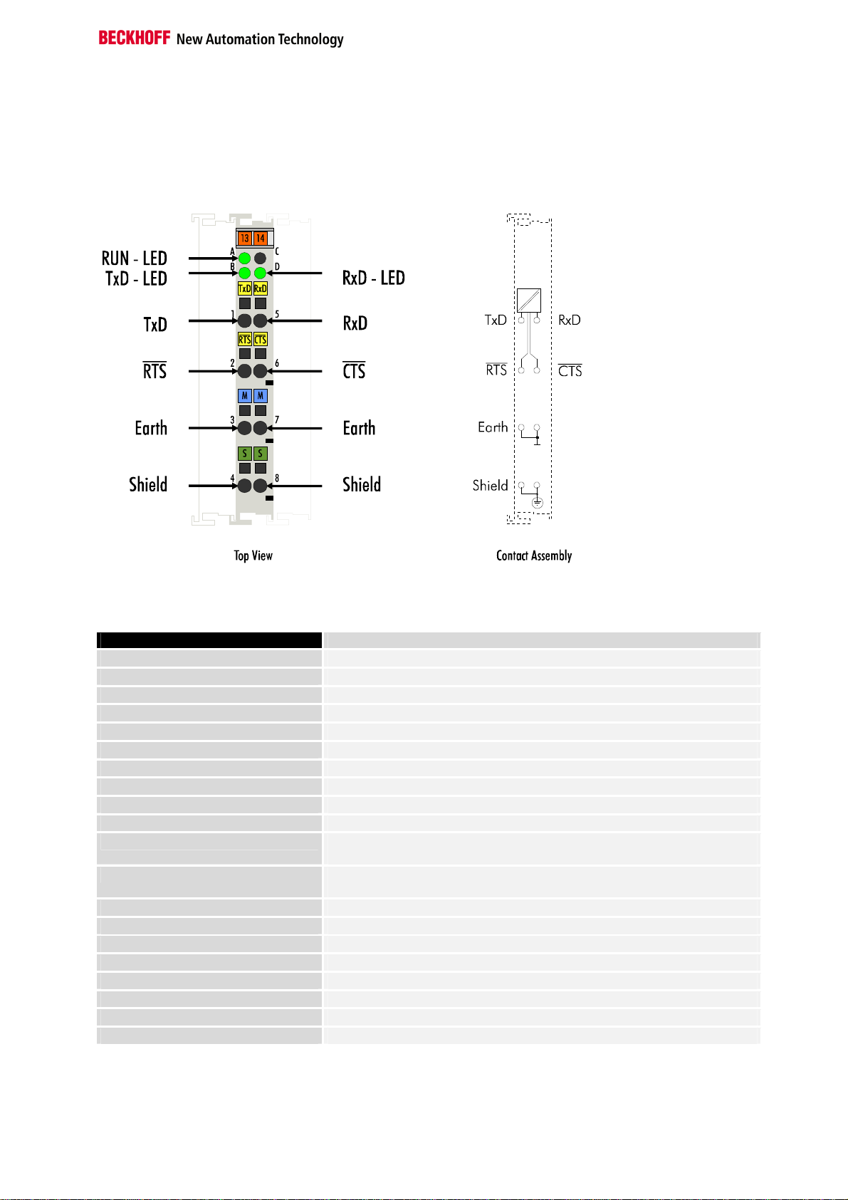
The Run LED indicates the operating state of the terminal.
On – normal operation
Off – watchdog timer overflow has occurred. The green LED goes off if no
process data is transferred from the bus coupler for 100 ms.
The TxD and RxD LEDs indicate the states of the signal lines.
2 bytes of control / status byte) are mapped in the bus coupler. When delivered, the KL6001 is set to the alternative format. Mapping of the terminal
in the alternative format is described in further detail in the chapter entitled
"Terminal Configuration".
By default, in the standard output format 4 bytes (3 bytes of user data and
1 control / status byte) are mapped in the bus coupler. Up to 5 bytes of
user data can be transferred by redefining the parameters of the KL6001.
The annex contains an over view of possible mapping configurations depending on the parameters that can be set.
Terminal configuration
The terminal can be configured and parametrized via the internal register
structure.
Each terminal channel is mapped in the bus coupler. The data of the terminal is mapped differently in the memory of the bus coupler depending on
the type of the bus coupler and on the set mapping configuration (eg Motorola / Intel format, word alignment.
For parametrization of a terminal, the control / status byte must also be
mapped.
When using the Beckhoff Lightbus coupler BK2000, the control / status
byte is always mapped in additon to the data bytes. It is always in the low
byte at the offset address of the terminal channel. In the case of the
KL6001 the C/S byte is only used in the register mode. The serial C/S byte
is used for the protocol.
6 KL6001
Page 7

Offset Terminal1 = 0
Offset Termianl2 Channel1 = 4
Offset Terminal3 Channel1 = 8
User data allocation depending
To the bus terminal
Offset Termianl1 Channel1 = 0
Offset Termianl2 Channel2 = 7
To the bus terminal
Beckhoff-Lightbus
bus coupler
BK2000
The terminal is
mapped in the
bus coupler.
0
K-Bus
C/S
Data H Data L
C/S
D2
Data L
C/S
D1
--
Ser. C/SD0
-
C/S
Data H
LH
Terminal configuration
on mapping.
KL6001
Profibus coupler BK3000
When using the Profibus coupler BK3000, how the KL6001 is to map itself
in the bus coupler is set in the master configuration software. When delivered, the KL6001 is set to the alternative format. Please pay attention to
the registers 34 and 35 if you wish to set the standard format and a different user data length. The figure shows the mapping for 4 bytes of input
data and 4 bytes of output data.
Profibus bus coupler
BK3000
The terminal is
mapped in the
bus coupler.
Data H
C/S
Data L
Data H
C/S
D1
D2
Ser.-C/S
0
D0
D2
The control/status byte
must be inserted for
parameterization.
Offset Termial2 Channel1 = 4
KL6001
K-Bus
Interbus coupler BK4000
KL6001 7
By default, the Interbus coupler BK4000 maps the KL6001 with 4 bytes of
input data and 4 bytes of output data. Parametrization via the field bus is
not possible. The KS2000 software is needed to redefine the terminal’s
parameters.
Page 8

Register description
Offset Terminal1 Channel1 = 0
Offset Termianl2 Channel1 = 4
Offset Termianl2 Channel1 = 6
To the bus terminal
i
Interbus bus coupler
BK4000
The termianl is
mapped in the
bus coupler.
K-Bus
The control/status byte
must be inserted for
Data H
Data L
Data H
Data L
Data H
D1
D2
Ser.-C/S
0
D0
parameterization (KS2000).
KL6001
Other bus couplers and
further information
Note
Parametrization with the
KS2000 software
You will find further information of the mapping configuration of bus couplers in the annex of the respective bus coupler manual under the heading
of "Configuration of Masters".
The annex contains an overview of possible mapping configurations depending on the parameters that can be set.
Parametrization operations can be carried out independently of the field
bus system using the Beckhoff KS2000 configuration software via the serial configuration interface in the bus coupler.
Register description
8 KL6001
The complex terminals can be adjusted to different operating modes or
functionalities. The " general description of register " describes the contents of the registers, which are identical for all complex terminals.
The terminal-specific registers are explained in the section following to it.
The access to the internal registers of the terminal is described in the sec-
tion " register communication ".
General register description
Complex terminals that possess a processor are capable of bidirectionally
ex-changing data with the higher-level control system. Below, these terminals are referred to as intelligent bus terminals. They include the analog
inputs (0-10V, -10-10V, 0-20mA, 4-20mA), the analog outputs (0-10V, -1010V, 0-20mA, 4-20mA), serial interface terminals (RS485, RS232, TTY,
data transfer terminals), counter terminals, encoder interfaces, SSI interfaces, PWM terminals and all other parametrizable terminals.
Internally, all intelligent terminals possess a data structure that is identical
in terms of it's essential characteristics. This data area is organized in
words and embraces 64 memory locations. The essential data and parameters of the terminal can be read and adjusted by way of the structure.
Function calls with corresponding parameters are also possible. Each logical channel of an intelligent terminal has such a structure (therefore, 4channel analog terminals have 4 register sets.
Page 9

Register description
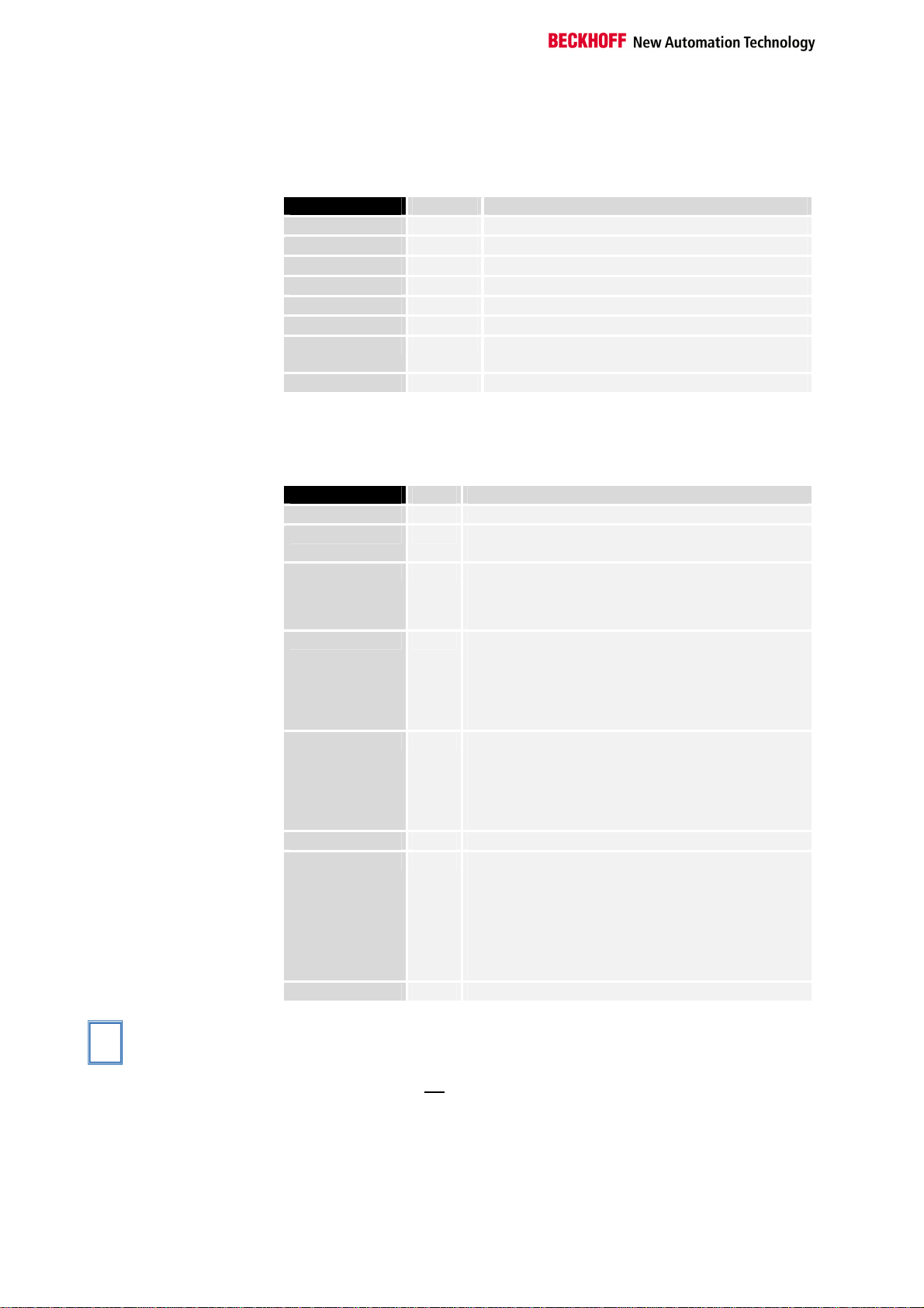
This structure is broken down into the following areas:
(You will find a list of all registers at the end of this documentation).
Area Address
Process variables
Type registers
Manufacturer parameters
User parameters
Extended user area
0-7
8-15
16-30
31-47
48-63
Process variables R0 - R7: Registers in the terminal’s internal RAM:
The process variables can be used in additional to the actual process image and their functions are specific to the terminal.
R0 - R5: These registers have a function that depends on the terminal
type.
R6: Diagnostic register
The diagnostic register may contain additional diagnostic information. In
the case of serial interface terminals, for example, parity errors that have
occurred during data transfer are indicated.
R7: Command register
High-Byte_Write = function parameter
Low-Byte _Write = function number
High-Byte _Read = function result
Low-Byte_ Read = function number
Type registers R8 - R15 Registers in the terminal’s internal ROM der Klemme
The type and system parameters are programmed permanently by the
manufacturer and can only be read by the user but cannot be modified.
R8: Terminal type:
The terminal type in register R8 is needed to identify the terminal.
R9: Software version X.y
The software version can be read as an ASCII character string.
R10: Data length
R10 contains the number of multiplexed shift registers and their length in
bits.
The bus coupler sees this structure.
R11: Signal channels
In comparison with R10, the number of logically existing channels is located here. For example, one physically existing shift register may consist
of several signal channels.
R12: Minimum data length
The respective byte contains the minimum data length of a channel to be
transferred. If the MSB is set, then the control/status byte is not necessarily
needed for the function of the terminal and, with appropriate configuration
of the coupler, is not transferred to the control system.
KL6001 9
Page 10

Register description
i
R13: Data type register
Data type register
0x00
0x01
0x02
0x03
0x04
0x05
0x06
0x07
0x08
0x11
0x12
0x13
0x14
0x15
0x16
Terminal without valid data type
Byte array
1 byte n bytes structure
Word array
1 byte n words structure
Double word array
1 byte n double words structure
1 byte 1 double word structure
1 byte 1 double word structure
Byte-array with a variable logical channel length
1 byte n bytes structure with a variable logical channel
length (eg 60xx)
Word-array with a variable logical channel length
1 byte n words structure with a variable logical channel
length
Double word array with a variable logical channel length
1 byte n double words structure with a variable logical
channel length
R14: not used
R15: Alignment bits (RAM)
The analog terminal is set to a byte limit in the terminal bus with the alignment bits.
Manufacturer parameters R16 - R30 is the area of the "Manufacturer parameters" (SEEROM)
The manufacturer parameters are specific to each terminal type. They are
programmed by the manufacturer but can also be modified from the control
system. The manufacturer parameters are stored permanently in a serial
EEPROM and are therefore not destroyed by power failures.
These registers can only be modified after setting a code word in R31.
User parameters
R31 - R47 "Application parameters" area (SEEROM)
The application parameters are specific to each terminal type. They can be
modified by the programmer. The application parameters are stored permanently in a serial EEPROM in the terminal and cannot be destroyed by
power failures. The user area is write protected over a Codeword.
R31: Code word-register in the RAM
The code word 0x1235 must be entered here to enable modification of
Note
parameters in the user area. Write-protection is set if a different value is
entered in this register. When write protection is inactive, the code word is
returned during reading of the register. The register contains the value zero
when write protection is active.
R32: Feature-register
This register defines the operating modes of the terminal. For example, a
user-specific scaling can be activated for the analog I/O’s.
R33 - R47
Registers that depend on the terminal type
Extended application area R47 - R63
These registers have not yet been implemented.
10 KL6001
Page 11

Terminal-specific register description
Process variables R0: Number of data bytes in the send FIFO
The number of data items in the send FIFO is in the low byte. The high
byte is not used.
R1: Number of data bytes in the receive FIFO
The low byte contains the number of data in the receive FIFO. The high
byte is not used.
R2 - R5: no function
R6: Diagnostic register
High byte: not used
Low byte: status of the receive channel (bits 0 – 7)
Bit No. Meaning
Bit 0
Bit 1
Bit 2
Bit 3
Bit 4
Bits 5 - 15
1 The receive buffer has overflown and arriving
data is lost.
1 Parity error has occurred.
1 Framing error has occurred.
1 Over run error has occurred.
1 Buffer is full
- not used, don't change
Manufacturer parameters R18: Buffer size
[0x0080]
Register R18 defines the number of data items in the receive FIFO as from
which the BUF_F bit is set in the status byte.
Low byte: BUF_F is set in the status if this value is reached.
High byte: not used
User parameters R32: Baud rate:
[0x0006]
Bit No. Baud rate
Bit 2 Bit 1 Bit 0
Bits 3 - 15
0 1 1 1200 Baud
1 0 0 2400 Baud
1 0 1 4800 Baud
1 1 0 9600 Baud [1 1 0]
1 1 1 19200 Baud
- not used, don't change
The baud rate can also be set in accordance with the following equation:
Baud rate = 4 MHz/(16*(HB+1))
At the same time, 0xFF must be written into the low byte and the high byte
(HB) specifies the operator.
Register description
KL6001 11
Page 12
Register description
Continuous transmitting of the data from the Fifo.
i
R33: Data frame
[0x0003]
The data frame is set in this register.
Bit No. Meaning
Bit 2 Bit 1 Bit 0
Bit 3
Bits 4- 15
0 0 1 7 data bits, even-parity
0 1 0 7 data bits, odd-parity
0 1 1 8 data bits, no parity [0 1 1]
1 0 0 8 data bits, even-parity
1 0 1 8 data bits, odd-parity
0/1 0: 1 stop bit [0]
1: 2 stop bits
- not used, don't change
R34: Feature register:
[0x0003]
The feature register determines the operating modes of the terminal.
Feature Bit No. Mode description
Bit 0
Bit 1
Bit 2
Bit 3
Bit 4
Bit 5
Bit 6
Bits 7 - 15
1 /RTS, /CTS enable [1]
0/1 0: standard output format (see R35 !)
1: alternative output format [1]
1 The terminal copies the status byte into the shift re-
gister of the K bus one cycle later than the more significant data bytes, thus reducing the data transfer
rate to the controller.[0]
1 The terminal supports the XON/XOFF protocol
when sending data, i.e. the terminal sends the data
transferred from the controller until it receives the
XOFF (DC3==0x13) signal from the partner. Sending is then suppressed until the XON (DC1==0x11)
signal is received. [0]
1 The terminal supports the XON/XOFF protocol
when receiving data. The terminal sends the XOFF
control character when the terminal’s buffer contains 118 characters. XON is sent if XOFF has been
sent beforehand and the buffer’s contents have fallen below the buffer limit. of 18 bytes. [0]
- not used, don't change
1
The transmit buffer is filled over the control (PC or
PLC; up to 16 byte). With rising flank in the Controlbyte.3 the filled buffer content is transmitted. If the
data are transferred, then this is acknowledged by
setting the bit Status-byte.2 by the bus terminal to
the Control. Status-byte.2 is taken back with Control-byte.3.
- not used, don't change
This documentation is valid for all bus terminals starting from software ver-
Note for bit 6
sion 3x. The version specification can be found on the right side of the bus
terminal, in the serial number: xxxx3xxx
For example: 52983A2A ⇒ Software version 3A
R35: Number of data bytes mapped in the bus coupler
[0x0003]
Low byte: number of data bytes in the bus coupler and transferred to the
controller. Between 1 and 5 data bytes can be transferred. If more than 3
bytes of user data are to be transferred, the new number of bytes must be
entered in this register.
High byte = not used
12 KL6001
Page 13

0
63
Terminal´s
Control-/
HHL
L
Register communication KL6001
Register access via
process data transfer
Bit 7=1: register mode
When bit 7 of the control byte is set, the first two bytes of the user data are
not used for process data transfer, but are written into or read out of the
terminal’s register.
Bit 6=0: read
Bit 6=1: write
In bit 6 of the control byte, you define whether a register is to be read or
written. When bit 6 is not set, a register is read without modification. The
value can be taken from the input process image.
When bit 6 is set, the user data is written into a register. The operation is
concluded as soon as the status byte in the input process image has supplied an acknowledgement (see examples).
Bits 0 to 5: address
The address of the register to be addressed is entered in bits 0 to 5 of the
control byte.
Control byte in the
register mode
MSB
REG=1 W/R
REG = 0 : Process data transfer
REG = 1 : Access to register structure
W/R = 0 : Read register
W/R = 1 : Write register
A5..A0 = Register address
A total of 64 registers can be addressed with the addresses A5....A0.
To the bus coupler
Register description
A5
A4
A3
A2
A1
A0
K-Bus
User data
status byte
2 or mors bytes
If control bit 7=0: input/output
If control bit 7=1:
C/S-bit 7
If control bit 7=1:
adress in the control bit 0-5
registerconfiguration
If control bit 6=0: read
If control bit 6=1: write
register set
64 words
Complex bus terminal
The control or status byte occupies the lowest address of a logical channel.
The corresponding register values are located in the following 2 data bytes
(the BK2000 is an exception to the rule: here, an unused data byte is inserted after the control or status byte, thus setting the register value to a
word limit).
KL6001 13
Page 14

Data transfer, function
Example
A further example
Control byte in
process data transfer
Status byte in
process data mode
TR/TA:TRANSMITREQUEST/ TRANSMITACCEPTED bits
Reading register 8 in the BK2000 with a Kl3022 and the end terminal.
If the following bytes are transferred from the controller to the terminal,
Byte0
Control
Byte1
Not used
Byte2
Data OUT, high byte
Byte3
Data OUT, low byte
0x88 0xXX 0xXX 0xXX
the terminal returns the following type designation (0x0BCE corresponds to
the unsigned integer 3022).
Byte0
Status
Byte1
Not used
Byte2
Data IN, high byte
Byte3
Data IN, low byte
0x88 0x00 0x0B 0xCE
Writing register 31 in the BK2000 with an intelligent terminal and the end
terminal.
If the following bytes (user code word) are transferred from the controller to
the terminal,
Byte0
Control
Byte1
Not used
Byte2
Data OUT, high byte
Byte3
Data OUT, low byte
0xDF 0xXX 0x12 0x35
the user code word is set and the terminal returns the register address with
the bit 7 for register access and the acknowledgement.
Byte0
Status
Byte1
Not used
Byte2
Data IN, high byte
Byte3
Data IN, low byte
0x9F 0x00 0x00 0x00
Data transfer, function
The control byte is transferred from the terminal to the controller. It can be
used in the register mode (REG = 1) or in the process data transfer (REG =
0) (see remark in the annex). The control and status byte in process data
transfer is used to handle data transfer (handshake)
MSB
REG=0 OL2 OL1 OL0 0 IR RA TR
The status byte is transferred from the terminal to the controller. It contains
the data needed for the handshake.
MSB
REG=0 IL2 IL1 IL0 BUF_F IA RR TA
The handshake for sending the data is realized by way of this bit. A change
of state on the part of TR results in loading of the number of data items
defined via OL0-OL2 (up to 5) into the send FIFO. The terminal signals
execution of this command via TA.
14 KL6001
Page 15

Example
Data bytes: in D0 and D1
Data bytes: in D0 and D1
Data bytes in D0 to D4
Data bytes: in D0 und D1
RA/RR:REICEIVEACCEPTED/RECEIVEREQUEST
By way of a status change of RR, the terminal informs the controller that
the number of data items indicated in IL0-IL1 is located in D0-D4. Transfer
of the data is acknowledged in the control byte with RA, and only then is
new data transferred from the terminal to the controller.
Example
Output
control byte
00000000
0XXX000X
0XXX001X
0XXX001X
0XXX000X
IR/IA:
INIT-REQUEST/INITACCEPTED
The terminal performs initialization if IR is high. The send and receive functions are disabled, the FIFO flags are reset and the interface is initialized
with the values of the responsible registers (R32-R35,R18). The terminal
acknowledges execution of initialization with IA.
Example
Output
control byte
0XXXXXXX
00000100
00000100
00000000
00000000
Output
Control byte
00000000
00100001
....
00100001
01010000
....
01010000
Input
status byte
0XXXX00X Start of data transfer
0011X01X
....
....
0011X01X
0101X00X
....
....
0101X00X
Input
status byte
0XXXXXXX Start of data transfer
0XXXXXXX Initialization is requested by the con-
....
....
00000100
00000100
....
....
00000000
Data transfer, function
Input
status byte
0XXXX0X0 Start of data transfer
0XXXX0X0
....
0XXXX0X1
0XXXX0X1
Data bytes:DC
....
0XXXX0X0
Comment
Controller requests sending of
2-data from the terminal
Terminal has loaded 2-data
into the send FIFO and thecommand has been executed.
Controller requests sending of
5-data (D0-D4) from the terminal
Terminal has loaded 5-data
into the send FIFO and the
command has been executed
Comment
Terminal requests acceptance of 3data from D0-D2 by the controller.
Controller has accepted data
Terminal requests acceptance of
5-data from D0-D4 by the controller
Controller has accepted data
Comment
troller.
Terminal has completed initialization
Controller requests data exchange
Terminal is ready
KL6001 15
Page 16

Data transfer, function
BUF_F:
BUFFER-FULL_Flag
Error handling
The receive FIFO is full. Data that is now received is lost.
If a parity, framing or overrun error occurs, the data item concerned is lost,
and it is not loaded into the terminal’s receive FIFO.
Incoming data is ignored if the buffer is full.
The corresponding diagnostic bits are set in R6 if an error occurs.
16 KL6001
Page 17

Standard format
Alternative format
Default: CANCAL,
CANopen, RS232,
RS485, ControlNet,
DeviceNet
Default: Interbus,
Profibus
Annex
As already described in the chapter terminal configuration, each bus terminal is mapped in the bus coupler. In the standard case, this mapping is
done with the default setting in the bus coupler / bus terminal. This default
setting can be modified with the Beckhoff KS2000 configuration software or
using master configuration software (e.g. ComProfibus or TwinCAT System
Manager). The following tables provide information on how the KL6001
maps itself in the bus coupler depending on the set parameters.
Mapping in the bus coupler
In the standard format, by default the KL6001 is mapped with 4 bytes (adjustable: 2 to 6 bytes via R35) of input and output data.
Remark: in the standard format, the CT/ST byte is used for register and
process data communication.
I/O Offset High Byte Low Byte
Complete evaluation = X 3
MOTOROLA format = X 2 D4(opt.) D3(opt.)
Word alignment = X 1 D2(opt.) D1(opt.)
0 D0 CT/ST
In the alternative format, the KL6001 is mapped with 4/6 bytes of input data
and 4/6 bytes of output data. When delivered the KL6001 is set to the alternative format.
Remark: in the alternative format, the CT/ST byte is used only for register
communication and the serial CT/ST byte is used only for the data handshake.
I/O Offset High Byte Low Byte
Complete evaluation = 0 3
MOTOROLA format = 0 2
Word alignment = 0 1 D2 D1
0 D0 Ser-CT/ST
I/O Offset High Byte Low Byte
Complete evaluation = 0 3
MOTOROLA format = 1 2
Word alignment = 0 1 D1 D2
0 Ser-CT/ST
I/O Offset High Byte Low Byte
Complete evaluation = 1 3
MOTOROLA format = 0 2 D2 D1
Word alignment = 0 1 -- D0
0 Ser-CT/ST
I/O Offset High Byte Low Byte
Complete evaluation = 1 3
MOTOROLA format = 1 2 D1 D2
Word alignment = 0 1 -- Ser-CT/ST
0 D0 CT/ST
Annex
D0
CT/ST
KL6001 17
Page 18

Annex
Default: Lightbus,
Bus Terminal Controller
(BCxxxx)
I/O Offset High Byte Low Byte
Complete evaluation = 1 3 D2 D1
MOTOROLA format = 0 2 -- -Word alignment = 1 1 D0 Ser-CT/ST
0 -- CT/ST
I/O Offset High Byte Low Byte
Complete evaluation = 1 3 D1 D2
MOTOROLA format = 1 2 -- -Word alignment = 1 1 Ser-CT/ST
0 -- CT/ST
Legend
Complete evaluation: the terminal is mapped with control / status byte.
Motorola format: the Motorola or Intel format can be set.
Word alignment: the terminal is at a word limit in the bus coupler.
CT: Control byte (appears in the PI of the outputs).
ST: Status byte (appears in the PI of the inputs).
Ser.-CT: control byte for the handshake (appears in the PI of the outputs)
Ser.-ST: status byte for the handshake (appears in the PI of the inputs)
D0 – D4: data bytes 0 – 4
D0
18 KL6001
Page 19

Table of the register
Register set
Address Description Default value R/W Storage medium
R0
Number of data bytes in the send buffer variable R RAM
R1
Number of data bytes in the receive buffer variable R RAM
R2
not used 0x0000 R
R3
not used 0x0000 R
R4
not used 0x0000 R
R5
not used 0x0000 R
R6
Diagnostic register variable R RAM
R7
Command register - not used 0x0000 R
R8
Terminal type 6001 R ROM
R9
Software version number 0x???? R ROM
R10
R11
R12
R13
R14
R15
R16
R17
R18
R19
R20
R21
R22
R23
R24
R25
R26
R27
R28
R29
R30
R31
R32
R33
R34
R35
R36
R37
R38
R39
R40
R41
R42
R43
R44
R45
R46
R47
Multiplex shift register 0x0218 R ROM
Signal channels 0x0130 R ROM
Minimum data length 0x3030 R ROM
Data structure 0x0000 R ROM
not used 0x0000 R
Alignment register variable R/W RAM
Hardware version number specific R/W SEEROM
not used 0x0000 R/W SEEROM
Buffer full indication 0x0080 R/W SEEROM
not used 0x0000 R/W SEEROM
not used 0x0000 R/W SEEROM
not used 0x0000 R/W SEEROM
not used 0x0000 R/W SEEROM
not used 0x0000 R/W SEEROM
not used 0x0000 R/W SEEROM
not used 0x0000 R/W SEEROM
not used 0x0000 R/W SEEROM
not used 0x0000 R/W SEEROM
not used 0x0000 R/W SEEROM
not used 0x0000 R/W SEEROM
not used 0x0000 R/W SEEROM
Code word register variable R/W RAM
Baud rate 0x0006 R/W SEEROM
Data frame 0x0003 R/W SEEROM
Feature register 0x0002 R/W SEEROM
Number of data bytes to the bus coupler 0x0003 R/W SEEROM
not used 0x0000 R/W SEEROM
not used 0x0000 R/W SEEROM
not used 0x0000 R/W SEEROM
not used 0x0000 R/W SEEROM
not used 0x0000 R/W SEEROM
not used 0x0000 R/W SEEROM
not used 0x0000 R/W SEEROM
not used 0x0000 R/W SEEROM
not used 0x0000 R/W SEEROM
not used 0x0000 R/W SEEROM
not used 0x0000 R/W SEEROM
not used 0x0000 R/W SEEROM
Annex
KL6001 19
Page 20

Annex
Support and Service
Beckhoff and their partners around the world offer comprehensive support and service, making available
fast and competent assistance with all questions related to Beckhoff products and system solutions.
Beckhoff's branch offices and representatives
Please contact your Beckhoff branch office or representative for local support and service on Beckhoff
products!
The addresses of Beckhoff's branch offices and representatives round the world can be found on her
internet pages: http://www.beckhoff.com
You will also find further documentation for Beckhoff components there.
Beckhoff Headquarters
Beckhoff Automation GmbH
Eiserstr. 5
33415 Verl
Germany
phone: + 49 (0) 5246/963-0
fax: + 49 (0) 5246/963-198
e-mail: info@beckhoff.com
web: www.beckhoff.com
Beckhoff Support
Support offers you comprehensive technical assistance, helping you no only with the application of individual Beckhoff products, but also with other, wide-ranging services:
• support
• design, programming and commissioning of complex automation systems
• and extensive training program for Beckhoff system components
hotline: + 49 (0) 5246/963-157
fax: + 49 (0) 5246/963-9157
e-mail: support@beckhoff.com
Beckhoff Service
The Beckhoff Service Center supports you in all matters of after-sales service:
• on-site service
• repair service
•
spare parts servive
• hotline service
hotline: + 49 (0) 5246/963-460
fax: + 49 (0) 5246/963-479
e-mail: service@beckhoff.com
20 KL6001
 Loading...