

Page 1

KL5121
Incremental Encoder Interface
with programmable Outputs
Configuration Instructions
Version 2.1
2006-10-23
Page 2

Contents
Contents
1. Foreword 3
Notes on the documentation 3
Safety Instructions 4
2. Technical data 5
3. Description of functions 6
4. Terminal configuration 7
5. Register description 8
General register description 8
Terminal-specific register description 11
Register communication KL5121 12
6. Data transfer, function 13
7. Annex 16
Mapping in the bus coupler 16
Table of the register 17
Support and Service 19
Beckhoff Headquarters 19
2 KL5121
Page 3

Foreword
Foreword
Notes on the documentation
This description is only intended for the use of trained specialists in control and automation engineering
who are familiar with the applicable national standards. It is essential that the following notes and
explanations are followed when installing and commissioning these components.
Liability Conditions
The responsible staff must ensure that the application or use of the products described satisfy all the
requirements for safety, including all the relevant laws, regulations, guidelines and standards.
The documentation has been prepared with care. The products described are, however, constantly under
development. For that reason the documentation is not in every case checked for consistency with
performance data, standards or other characteristics. None of the statements of this manual represents a
guarantee (Garantie) in the meaning of § 443 BGB of the German Civil Code or a statement about the
contractually expected fitness for a particular purpose in the meaning of § 434 par. 1 sentence 1 BGB. In
the event that it contains technical or editorial errors, we retain the right to make alterations at any time
and without warning. No claims for the modification of products that have already been supplied may be
made on the basis of the data, diagrams and descriptions in this documentation.
Delivery conditions
In addition, the general delivery conditions of the company Beckhoff Automation GmbH apply.
Copyright
©
This documentation is copyrighted. Any reproduction or third party use of this publication, whether in
whole or in part, without the written permission of Beckhoff Automation GmbH, is forbidden.
KL5121
3
Page 4
Foreword
i
Safety Instructions
State at Delivery
All the components are supplied in particular hardware and software configurations appropriate for the
application. Modifications to hardware or software configurations other than those described in the
documentation are not permitted, and nullify the liability of Beckhoff Automation GmbH.
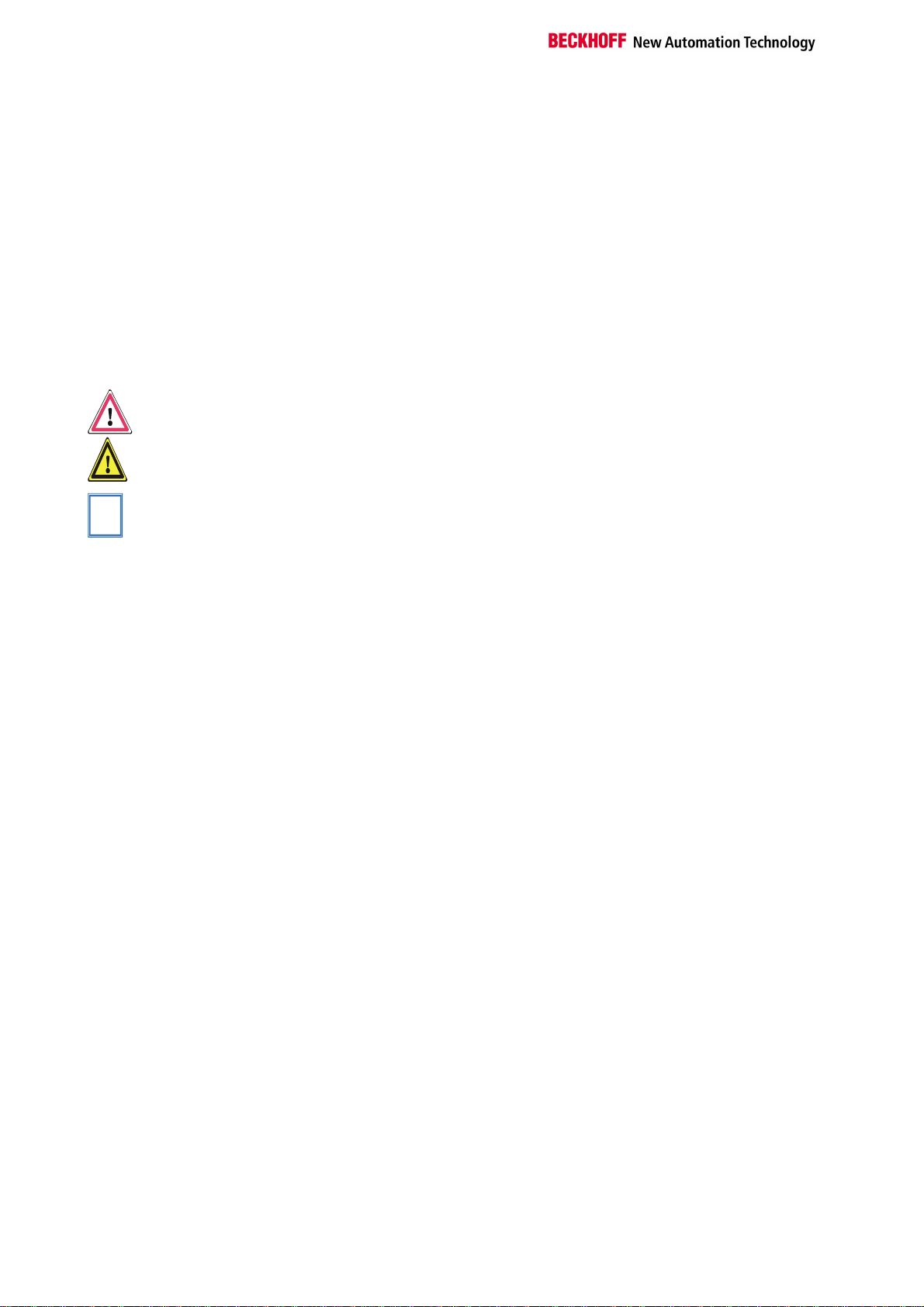
Description of safety symbols
The following safety symbols are used in this documentation. They are intended to alert the reader to the
associated safety instructions..
This symbol is intended to highlight risks for the life or health of personnel.
Danger
This symbol is intended to highlight risks for equipment, materials or the
Attention
environment.
This symbol indicates information that contributes to better understanding.
Note
4 KL5121
Page 5
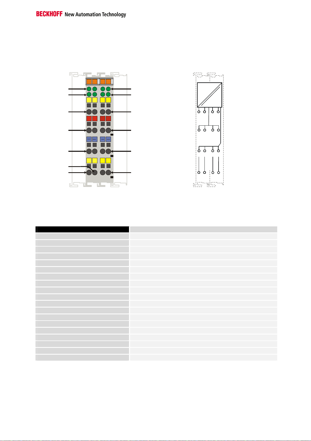
Contact Assembly
O1, O2
Latch, Gate
Technical data
13 15
A, B
Latch, Gate
14 16
A
B
C
D
O1A B
O2
Technical data
O1, O2
O3, O4
A, B O1, O2
Gate
1
+
2
3
L
G
4
5
+ ++
6
7
O4O3
8
Latch
Top View
Technical data KL5121
Sensor connection
Sensor operating voltage
Counter
Cut off frequency
Output voltage
Max. current per output
Switching time of the outputs
Supply voltage
Current consumption of Power contacts
Bit width in the Process image
Current consumption from K-Bus
Weight approx..
Operating temperature
Storage temperature
Relative humidity
Vibration/shock resistance
EMC resistance Burst / ESD
Installation position
Type of protection
A, B
+24 V (2x)+24 V (2x)
0 V (2x)0 V (2x)
0 V
O3, O4
A, B, Latch, Gate
24 V DC
16 bits binary
1 MHz
24 V DC
0.5 A
< 100 µs
24 V DC (20 V ... 29 V)
0.1 A (without sensor load current)
I/O: 2 x 16 bits data, 2 x 8 bits control/status
30 mA
60 g
0°C ... +55°C
-25°C ... +85°C
95%, no condensation
conforms to IEC 68-2-6 / IEC 68-2-27
conforms to EN 50082 (ESD, Burst) / EN 50081
any
IP20
+24 V+24 V
0 V
O3, O4
KL5121
5
Page 6

Description of functions
Operating modes
LED display
Process data
Connections
Description of functions
Four-channel linear path control can be implemented with the KL5121
function terminal. For this purpose the terminal reads in the incremental
signal (which is either supplied by an encoder or by a pulse generator),
obtains the position of the workpiece from another input (latch), and
switches on the outputs at defined counter states which have previously
been stored in the form of a table. Automatic speed correction is carried
out separately for each channel (adjustable by means of registers in the
terminal). The workpiece’s sensor edge can be configured, so that rising
edges, falling edges or both may be used. The switching times for the
individual output channels are < 100 µS. A maximum of 60 switching
values can be entered, and the number for each channel can vary from 0
to 60. The counter is limited to 16 bits, a tracking of the workpieces is not
possible.
Set by the control byte:
- linear path control with 4 output channels
- alternative: PWM type of output with pre-set on and off times (nozzle
test)
The signal LEDs indicate the state of the sensor inputs A and B, the latch
and gate logic inputs and of the four outputs O1, O2, O3 and O4.
The KL5121 always occupies 6 bytes of input data and 6 bytes of output
data. The control/status byte is located at the lowest byte offset.
There are two logical data channels: data channel 0 to enable the output
functions and for reading in the status information, while data channel 1 is
used to transmit the switch values in the terminal’s output table.
The KL5121 has 4 logical 24 V inputs and 4 logical 24 V outputs, as well as
8 contacts for the 24 V DC supply of external devices.
A, B: sensor inputs (incremental encoder or pulse generator)
Latch (workpiece sensor input): the latch input recognises the workpiece,
with the result that the 16 bit counter is set to zero when the latch input is
activated. The latch input can be configured by way of the feature register.
Gate (enable input): the gate enables the latch input. The gate input can be
configured by way of the feature register.
O1, O2, O3, O4: 24 V switch output
24 V/0 V: 24 V DC supply voltage for the external devices (e.g. encoder)
6 KL5121
Page 7

Offset Terminal1 Channel1 = 0
Offset Terminal2 Channel1 = 4
Offset Terminal2 Channel2 = 8
User data allocation depending
To the bus terminal
Offset Terminal1 Channel1 = 0
Offset Terminal1 Channel2 = 3
Offset Terminal2 Channel1 = 6
To the bus terminal
Beckhoff Lightbus
Coupler BK2000
Terminal configuration
Each terminal channel is mapped in the bus coupler. The terminal’s data is
mapped differently in the bus coupler’s memory depending on the type of
the bus coupler and on the set mapping configuration (eg.Motorola / Intel
format, word alignment,...).
In contrast to analogue input and output terminals, the KL5121 always also
maps the control and status byte, independently of the supervising fieldbus
system.
In the case of the Beckhoff Lightbus coupler BK2000, the control /status
byte is always mapped besides the data bytes. It is always in the low byte
at the offset address of the terminal channel.
Beckhoff-Lightbus
bus coupler
BK2000
The terminal is
mapped in the
bus coupler.
Terminal configuration
C/S
Data H Data L
C/S
Data LData H
C/S
D1 - 1
D1 - 0
0
D0 - 1
C/S - 1
D0 - 0
C/S - 0
on mapping
KL5121
Profibus Coupler BK3000
LH
K-Bus
In the BK3000 Profibus coupler, the KL5121 is always mapped with 6 bytes
of input data and 6 bytes of output data.
Profibus bus coupler
BK3000
The terminal is
mapped in the
bus coupler.
Data L
Data H
C/S
D0 - 1
D1 - 1
C/S - 1
D0 - 0
D1 - 0
C/S - 0
0
The control-/status byte
must be inserted for
parameterization.
KL 5121 Channel 2
KL 5121 Channel1
K-Bus
KL5121
7
Page 8

Register description
Offset Terminal1 Channel1 = 0
Offset Terminal1 Channel2 = 3
Offset Terminal2 Channel1 = 6
To the bus terminal
i
Interbus Coupler BK4000
The BK4000 Interbus coupler normally maps the KL5121 with 6 bytes of
input data and 6 bytes of output data.
Interbus bus coupler
BK4000
The terminal is
mapped in the
bus coupler.
K-Bus
The control-/status byte
must be inserted for
Data L
Data H
C/S
D0 - 1
D1 - 1
C/S - 1
D0 - 0
D1 - 0
C/S - 0
0
parameterization.
KL 5121 Channel 2
KL 5121 Channel1
Other bus couplers and
further information
Note
Parametrization with the
KS2000 software
You will find further information on the mapping configuration of bus
couplers in the annex of the respective bus coupler manual under the
heading of "Configuration of masters".
The annex contains an overview of the possible mapping configurations
depending on the adjustable parameters.
Parametrization operations can be carried out independantly of the field
bus system using the Beckhoff KS2000 configuration software via the
serial configuration interface in the bus coupler.
Register description
The complex terminals can be adjusted to different operating modes or
functionalities. The " general description of register " describes the
contents of the registers, which are identical for all complex terminals.
The terminal-specific registers are explained in the section following to it.
The access to the internal registers of the terminal is described in the
section " register communication ".
General register description
Complex terminals that possess a processor are capable of bidirectionally
ex-changing data with the higher-level control system. Below, these
terminals are referred to as intelligent bus terminals. They include the
analog inputs (0-10V, -10-10V, 0-20mA, 4-20mA), the analog outputs (010V, -10-10V, 0-20mA, 4-20mA), serial interface terminals (RS485, RS232,
TTY, data transfer terminals), counter terminals, encoder interfaces, SSI
interfaces, PWM terminals and all other parametrizable terminals.
Internally, all intelligent terminals possess a data structure that is identical
in terms of it's essential characteristics. This data area is organized in
8 KL5121
Page 9

Register description
words and embraces 64 memory locations. The essential data and
parameters of the terminal can be read and adjusted by way of the
structure. Function calls with corresponding parameters are also possible.
Each logical channel of an intelligent terminal has such a structure
(therefore, 4-channel analog terminals have 4 register sets.
This structure is broken down into the following areas:
(You will find a list of all registers at the end of this documentation).
Area Address
Process variables
Type registers
Manufacturer parameters
User parameters
Extended user area
0-7
8-15
16-30
31-47
48-63
Process variables R0 - R7: Registers in the terminal’s internal RAM:
The process variables can be used in additional to the actual process
image and their functions are specific to the terminal.
R0 - R5: These registers have a function that depends on the terminal
type.
R6: Diagnostic register
The diagnostic register may contain additional diagnostic information. In
the case of serial interface terminals, for example, parity errors that have
occurred during data transfer are indicated.
R7: Command register
High-Byte_Write = function parameter
Low-Byte _Write = function number
High-Byte _Read = function result
Low-Byte_ Read = function number
Type registers R8 - R15 Registers in the terminal’s internal ROM der Klemme
The type and system parameters are programmed permanently by the
manufacturer and can only be read by the user but cannot be modified.
R8: Terminal type:
The terminal type in register R8 is needed to identify the terminal.
R9: Software version X.y
The software version can be read as an ASCII character string.
R10: Data length
R10 contains the number of multiplexed shift registers and their length in
bits.
The bus coupler sees this structure.
R11: Signal channels
In comparison with R10, the number of logically existing channels is
located here. For example, one physically existing shift register may
consist of several signal channels.
R12: Minimum data length
The respective byte contains the minimum data length of a channel to be
transferred. If the MSB is set, then the control/status byte is not necessarily
needed for the function of the terminal and, with appropriate configuration
of the coupler, is not transferred to the control system.
KL5121
9
Page 10

Register description
i
R13: Data type register
Data type register
0x00
0x01
0x02
0x03
0x04
0x05
0x06
0x07
0x08
0x11
0x12
0x13
0x14
0x15
0x16
Terminal without valid data type
Byte array
1 byte n bytes structure
Word array
1 byte n words structure
Double word array
1 byte n double words structure
1 byte 1 double word structure
1 byte 1 double word structure
Byte-array with a variable logical channel length
1 byte n bytes structure with a variable logical channel
length (eg 60xx)
Word-array with a variable logical channel length
1 byte n words structure with a variable logical channel
length
Double word array with a variable logical channel length
1 byte n double words structure with a variable logical
channel length
R14: not used
R15: Alignment bits (RAM)
The analog terminal is set to a byte limit in the terminal bus with the alignment bits.
Manufacturer parameters R16 - R30 is the area of the "Manufacturer parameters" (SEEROM)
The manufacturer parameters are specific to each terminal type. They are
programmed by the manufacturer but can also be modified from the control
system. The manufacturer parameters are stored permanently in a serial
EEPROM and are therefore not destroyed by power failures.
These registers can only be modified after setting a code word in R31.
User parameters
R31 - R47 "Application parameters" area (SEEROM)
The application parameters are specific to each terminal type. They can be
modified by the programmer. The application parameters are stored
permanently in a serial EEPROM in the terminal and cannot be destroyed
by power failures. The user area is write protected over a Codeword.
R31: Code word-register in the RAM
The code word 0x1235 must be entered here to enable modification of
Note
parameters in the user area. Write-protection is set if a different value is
entered in this register. When write protection is inactive, the code word is
returned during reading of the register. The register contains the value zero
when write protection is active.
R32: Feature-register
This register defines the operating modes of the terminal. For example, a
user-specific scaling can be activated for the analog I/O’s.
R33 - R47
Registers that depend on the terminal type
Extended application area R47 - R63
These registers have not yet been implemented.
10 KL5121
Page 11

Terminal-specific register description
Process variables
R0-R3: Pulse for speed correction of channels 1-4
R4-R7: No function
Manufacturer parameter R17-R30: Not used
Application parameter R32: Feature register:
This register describes the (hardware) settings for channels 1-4 [0x0062]
Feature Bit No.
Bit 0
Bit 1
Bit 2
Bit 3
Bit 4
Bit 5
Bit 6
Bit 7-11
Bit 12-15
0/1 0: encoder operating mode with 4-fold
0/1 Latch input:
0/1 Latch input:
0/1 0: the outputs are switched according to positive
0/1 0: watchdog timer active [0]
1 1: workpiece sensor input (latch) is active [1]
1 1: workpiece sensor input (latch) is active [1]
- Not used, don't change
0000
0001
R33: Pulse duration Ti for channel 1
[0x01F4] = 0.5 ms
Ti specifies pulse duration for the pulsed operation mode of channel 1 [µs]
R34: Hold-up time Tv for channel 1
[0x1388] = 5 ms
The pulses counted in the hold-up time Tv are included in the calculation of
the speed correction [µs]
R35: Period Td for channel 1
[0x4E20] = 20 ms
Period Td for the channel 1 nozzle test
R40-R43: Channel 2 register
R48-R51: Channel 3 register
R56-R59: Channel 4 register
Register description
Description of the operating mode
evaluation [0]
1: up/down counter (pulse generator) with A as
counter input and B as U/D input
0: rising edge is ignored
1: evaluate rising edge as start signal [1]
0: falling edge is ignored [0]
1: evaluate falling edge as start signal
logic [0]
1: the outputs are switched according to
negative logic
1: watchdog timer active. If the terminal does not
receive any process data from the K-bus for
100 ms the outputs are reset.
when there is a positive level at the enable
input (gate)
when there is a negative level at the enable
input (gate)
Pulse operation (R33-R35 activated) [0000]
Line operation (not yet implemented)
KL5121
11
Page 12

Register description
0
63
Terminal´s
Control-/
HHL
L
Register communication KL5121
Register access via
process data transfer
Bit 7=1: register mode
When bit 7 of the control byte is set, the first two bytes of the user data are
not used for process data transfer, but are written into or read out of the
terminal’s register.
Bit 6=0: read
Bit 6=1: write
In bit 6 of the control byte, you define whether a register is to be read or
written. When bit 6 is not set, a register is read without modification. The
value can be taken from the input process image.
When bit 6 is set, the user data is written into a register. The operation is
concluded as soon as the status byte in the input process image has
supplied an acknowledgement (see examples).
Bits 0 to 5: address
The address of the register to be addressed is entered in bits 0 to 5 of the
control byte.
Control byte in the
register mode
MSB
REG=1 W/R
REG = 0 : Process data transfer
REG = 1 : Access to register structure
W/R = 0 : Read register
W/R = 1 : Write register
A5..A0 = Register address
A total of 64 registers can be addressed with the addresses A5....A0.
To the bus coupler
A5
A4
A3
A2
A1
A0
K-Bus
User data
status byte
2 or mors bytes
If control bit 7=0: input/output
If control bit 7=1:
C/S-bit 7
If control bit 7=1:
adress in the control bit 0-5
registerconfiguration
If control bit 6=0: read
If control bit 6=1: write
register set
64 words
Complex bus terminal
The control or status byte occupies the lowest address of a logical channel.
The corresponding register values are located in the following 2 data bytes
(the BK2000 is an exception to the rule: here, an unused data byte is
inserted after the control or status byte, thus setting the register value to a
word limit).
12 KL5121
Page 13

Data transfer, function
Example
A further example
Process data
Data channel 0
Controller output data
Controller input data
Control byte 0
Reading register 8 in the BK2000 with a Kl3022 and the end terminal.
If the following bytes are transferred from the controller to the terminal,
Byte0
Control
Byte1
Not used
Byte2
Data OUT, high byte
Byte3
Data OUT, low byte
0x88 0xXX 0xXX 0xXX
the terminal returns the following type designation (0x0BCE corresponds to
the unsigned integer 3022).
Byte0
Status
Byte1
Not used
Byte2
Data IN, high byte
Byte3
Data IN, low byte
0x88 0x00 0x0B 0xCE
Writing register 31 in the BK2000 with an intelligent terminal and the end
terminal.
If the following bytes (user code word) are transferred from the controller to
the terminal,
Byte0
Control
Byte1
Not used
Byte2
Data OUT, high byte
Byte3
Data OUT, low byte
0xDF 0xXX 0x12 0x35
the user code word is set and the terminal returns the register address with
the bit 7 for register access and the acknowledgement.
Byte0
Status
Byte1
Not used
Byte2
Data IN, high byte
Byte3
Data IN, low byte
0x9F 0x00 0x00 0x00
Data transfer, function
The KL5121 terminal occupies 6 bytes in the coupler’s input process image
and 6 bytes in the output process image. There are two logical channels:
data channel 0 and data channel 1.
Data channel zero consists of the control byte 0, input data word 0, status
byte 0 and output data word 0. Enables for the output functions are
communicated through channel zero, and status information is read in.
Parameter data can also be accessed.
CT-0: control byte 0
D0-0, D1-0: the terminal’s input data word 0
ST-0: status byte 0
D0-0, D1-0: the terminal’s output data word 0
Control byte 0 is only used for register access.
MSB
REG=0
KL5121
13
Page 14

Data transfer, function
Status byte 0
The state of the inputs can be read through status byte 0.
MSB
REG=0 ERROR_
(reserved)
Output data word 0
The current counter state is read in the terminal’s output data word zero.
The terminal supplies output word zero.
Bit No. Meaning
Bit 0-15
Input data word 0
Channel-specific enables are made via the terminal’s input word zero.
A nibble of the data word is reserved for each channel.
Channel 1:
Nibble Meaning
0000
0001
0111
0011
0101
The other nibbles for channels 2 - 4 are used similarly.
Data channel 1
Data channel 1 transfers the switch values to the terminal. They are
temporarily stored in the terminal’s RAM. Access to this data set is identical
to access to the terminal’s register set.
Controller output data
CT-1: control byte 1
D0-1, D1-1: the terminal’s input data word 1
Controller input data
ST-1: status byte 1
D0-1, D1-1: the terminal’s output data word 1
Control byte 1
Control byte 1 is transmitted from the controller to the terminal, and is used
for access to the output table.
BIT
Current encoder counter state
No enable is present. If the automatic switching function was
previously active, it is reset, so that if a workpiece has
already been picked up it will not be processed further when
the automatic function becomes active again.
Enable for the automatic switching function
Enable for the “glue nozzle test”. If the automatic switching
function was previously active it is interrupted, and is
continued again when there is a change of operating mode,
provided that the enable is not reset (e.g. from 0001 to 0111
to 0001)
Output to high level. Interruption of the switching function if it
was previously active.
Output to low level. Interruption of the switching function if it
was previously active.
A_INPUT B_ INPUT LATCH_
INPUT
14 KL5121
Page 15

Bit No.
Bit 0-5
Bit 6
Bit 7
Status byte 1
Status byte 1 is transmitted from the terminal to the controller.
Bit No.
Bit 0-5
Bit 6
Bit
Output data word 1
Output data word AW1 returns the addressed table entry for a table
access.
Bit No. Meaning
Bit 0-15
Input data word 1
Input data word EW1 is written into the table by a controller write access.
Bit No. Meaning
Bit 0-15
Output table
The appropriate values for the corresponding function must be entered into
the output table (max. 60 switching values).
Index Entry
N+4
N+5
N+M+4
N+M+5
N+M+O+4
N+M+O+5
N+M+O+P+4
000000111111
0/1 0: read
0/1 Table bit
000000111111
0/1 Don't care
1
Content of the addressed table entry
Entry in the output table
0
Number, N, of entries for the first output
1
Number, M, of entries for the second output
2
Number, O, of entries for the third output
3
Number, P, of entries for the fourth output
4
Switch value 1 channel 1
...
Switch value N channel 1
Switch value 1 channel 2
...
Switch value M channel 2
Switch value 1 channel 3
...
Switch value O channel 3
Switch value 1 channel 4
Switch value P channel 4
Meaning
Address bits A0 to A5 of the output table
1: write
This bit must be set for table accesses.
If the controller sees a falling edge in the terminal
here, evaluation of the output table is started, so
that, if sorting or other tasks are necessary, they will
be performed.
Meaning
Address bits A0 to A5 of the output table
Acknowledge for table access
Data transfer, function
KL5121
15
Page 16

Annex
Default: CANCAL,
CANopen, RS232,
RS485, ControlNet,
DeviceNet
Default: Interbus,
Profibus
Default: Lightbus,
Bus Terminal Controller
(BCxxxx)
Legend
Annex
As already described in the chapter terminal configuration, each bus
terminal is mapped in the bus coupler. In the standard case, this mapping
is done with the default setting in the bus coupler / bus terminal. This
default setting can be modified with the Beckhoff KS2000 configuration
software or using master configuration software (e.g. ComProfibus or
TwinCAT System Manager). The following tables provide information on
how the KL5121 maps itself in the bus coupler depending on the set
parameters.
Mapping in the bus coupler
The KL5121 is mapped into the bus coupler depending on the set
parameters. The terminal always occupies memory space in the process
image of the inputs and outputs.
I/O Offset High Byte Low Byte
Complete evaluation = X 3
MOTOROLA format = 0 2 D1-1 D0-1
Word alignment = 0 1 CT/ST-0 D1-0
0 D0-0 CT/ST-0
I/O Offset High Byte Low Byte
Complete evaluation = X 3
MOTOROLA format = 1 2 D0-1 D1-1
Word alignment = 0 1 CT/ST-0 D0-0
0 D1-0 CT/ST-0
I/O Offset High Byte Low Byte
Complete evaluation = X 3 D1-1 D0-1
MOTOROLA format = 0 2 - CT/ST-0
Word alignment = 1 1 D1-0 D0-0
0 - CT/ST-0
I/O Offset High Byte Low Byte
Complete evaluation = X 3 D0-1 D1-1
MOTOROLA format = 1 2 - CT/ST-0
Word alignment = 1 1 D0-0 D1-0
0 - CT/ST-0
Complete evaluation: the terminal is mapped with control / status byte.
Motorola format: The Motorola or Intel format can be set.
Word alignment: The terminal is at a word limit in the bus coupler.
CT: Control Byte (appears in the PI of the outputs).
ST: Status Byte (appears in the PI of the inputs).
D0 - 0 : D0 = Data-Low-Byte, 0 = Channel 0
D1 – 1 : D1 = Data-High-Byte, 1 = Channel 1
16 KL5121
Page 17

Table of the register
Register set
Address Description Default R/W Storage medium
R0
Pulses for speed factor 1 variable R RAM
R1
Pulses for speed factor 2 variable R RAM
R2
Pulses for speed factor 3 variable R RAM
R3
Pulses for speed factor 4 variable R RAM
R4
not used 0x0000 R
R5
not used 0x0000 R
R6
Diagnostic register – not used 0x0000 R
R7
Command register - not used 0x0000 R
R8
Terminal type 5121 R ROM
R9
Software version number 0x???? R ROM
R10
R11
R12
R13
R14
R15
R16
R17
R18
R19
R20
R21
R22
R23
R24
R25
R26
R27
R28
R29
R30
R31
R32
R33
R34
R35
R36
R37
R38
R39
R40
R41
R42
R43
R44
R45
R46
R47
Multiplex shift register 0x0218 R ROM
Signal channels 0x0130 R ROM
Minimum data length 0x3030 R ROM
Data structure 0x0007 R ROM
not used 0x0000 R
Alignment register variable R/W RAM
Hardware version number 0x???? R/W SEEROM
not used 0x0000 R/W SEEROM
not used 0x0000 R/W SEEROM
not used 0x0000 R/W SEEROM
not used 0x0000 R/W SEEROM
not used 0x0000 R/W SEEROM
not used 0x0000 R/W SEEROM
not used 0x0000 R/W SEEROM
not used 0x0000 R/W SEEROM
not used 0x0000 R/W SEEROM
not used 0x0000 R/W SEEROM
not used 0x0000 R/W SEEROM
not used 0x0000 R/W SEEROM
Changed default setting variable R/W SEEROM
not used 0x0000 R/W SEEROM
Codeword register variable R/W RAM
Feature register 1 0x0062 R/W SEEROM
Pulse length Ti channel 1 0x01F4 R/W SEEROM
Hold-up time Tv channel 1 0x1388 R/W SEEROM
Period Td for the channel 1 nozzle
test
not used 0x0000 R/W SEEROM
not used 0x0000 R/W SEEROM
not used 0x0000 R/W SEEROM
not used 0x0000 R/W SEEROM
Feature register 2 0x0000 R/W SEEROM
Pulse length Ti channel 2 0x01F4 R/W SEEROM
Hold-up time Tv channel 2 0x1388 R/W SEEROM
Period Td for the channel 2 nozzle
test
not used 0x0000 R/W SEEROM
not used 0x0000 R/W SEEROM
not used 0x0000 R/W SEEROM
not used 0x0000 R/W SEEROM
0x4E20 R/W SEEROM
0x4E20 R/W SEEROM
Annex
KL5121
17
Page 18

Annex
Address Description Default R/W Storage medium
R48
R49
R50
R51
R52
R53
R54
R55
R56
R57
R58
R59
R60
R61
R62
R63
Feature register 3 0x0000 R/W SEEROM
Pulse duration Ti for channel 3 0x01F4 R/W SEEROM
Hold-up time Tv for channel 3 0x1388 R/W SEEROM
Period Td for the channel 3 nozzle test 0x4E20 R/W SEEROM
not used 0x0000 R/W SEEROM
not used 0x0000 R/W SEEROM
not used 0x0000 R/W SEEROM
not used 0x0000 R/W SEEROM
Feature register 4 0x0000 R/W SEEROM
Pulse duration Ti for channel 4 0x01F4 R/W SEEROM
Hold-up time Tv for channel 4 0x1388 R/W SEEROM
Period Td for the channel 4 nozzle test 0x4E20 R/W SEEROM
not used 0x0000 R/W SEEROM
not used 0x0000 R/W SEEROM
not used 0x0000 R/W SEEROM
not used 0x0000 R/W SEEROM
18 KL5121
Page 19

Annex
Support and Service
Beckhoff and their partners around the world offer comprehensive support and service, making available
fast and competent assistance with all questions related to Beckhoff products and system solutions.
Beckhoff's branch offices and representatives
Please contact your Beckhoff branch office or representative for local support and service on Beckhoff
products!
The addresses of Beckhoff's branch offices and representatives round the world can be found on her
internet pages: http://www.beckhoff.com
You will also find further documentation for Beckhoff components there.
Beckhoff Headquarters
Beckhoff Automation GmbH
Eiserstr. 5
33415 Verl
Germany
phone: + 49 (0) 5246/963-0
fax: + 49 (0) 5246/963-198
e-mail: info@beckhoff.com
web: www.beckhoff.com
Beckhoff Support
Support offers you comprehensive technical assistance, helping you no only with the application of
individual Beckhoff products, but also with other, wide-ranging services:
• support
• design, programming and commissioning of complex automation systems
• and extensive training program for Beckhoff system components
hotline: + 49 (0) 5246/963-157
fax: + 49 (0) 5246/963-9157
e-mail: support@beckhoff.com
Beckhoff Service
The Beckhoff Service Center supports you in all matters of after-sales service:
• on-site service
• repair service
•
spare parts servive
• hotline service
hotline: + 49 (0) 5246/963-460
fax: + 49 (0) 5246/963-479
e-mail: service@beckhoff.com
KL5121
19
 Loading...