

Page 1
Configuration Instructions for
KL5111-0000, KS5111-0000
Interface Terminal for Incremental Encoder
Version: 3.0.1
Date: 2008-09-16
Page 2

Page 3

Table of Contents
Table of Contents
1 Foreword 2
1.1 Notes on the Documentation 2
1.1.1 Liability Conditions 2
1.1.2 State at Delivery 2
1.1.3 Copyright 2
1.1.4 Description of safety symbols 3
1.2 Documentation Issue Status 3
2 Product Overview 4
2.1 Technical Data 4
2.2 Description of functions 5
2.3 Terminal configuration 6
3 Register description 8
3.1 Register Overview 8
3.2 General register description 9
3.2.1 Process variables 9
3.2.2 Manufacturer Parameters 11
3.2.3 User Parameters 11
3.3 Terminal-specific register description 12
3.3.1 Application parameters 12
3.4 Control and Status Byte 13
3.4.1 Process data exchange 13
3.4.2 Register Communication 15
3.4.3 Examples for the Register Communication 16
3.5 Mapping in the bus coupler 18
4 Appendix 19
4.1 Support and Service 19
4.1.1 Beckhoff's branch offices and representatives 19
4.2 Beckhoff Headquarters 19
KL5111-0000 1
Page 4

Foreword
1 Foreword
1.1 Notes on the Documentation
This description is only intended for the use of trained specialists in control and automation engineering
who are familiar with the applicable national standards. It is essential that the following notes and
explanations are followed when installing and commissioning these components.
1.1.1 Liability Conditions
The responsible staff must ensure that the application or use of the products described satisfy all the
requirements for safety, including all the relevant laws, regulations, guidelines and standards.
The documentation has been prepared with care. The products described are, however, constantly under
development. For that reason the documentation is not in every case checked for consistency with
performance data, standards or other characteristics. None of the statements of this manual represent s a
guarantee (Garantie) in the meaning of § 443 BGB of the German Civil Code or a statement about the
contractually expected fitness for a particular purpose in the meaning of § 434 par. 1 sentence 1 BGB. In
the event that it contains technical or editorial errors, we retain the right to make alterations at any time
and without warning. No claims for the modification of products that have already been supplied may be
made on the basis of the data, diagrams and descriptions in this documentation.
1.1.2 State at Delivery
All the components are supplied in particular hardware and software configurations appropriate for the
application. Modifications to hardware or software configurations other than those described in the
documentation are not permitted, and nullify the liability of Beckhoff Automation GmbH.
1.1.3 Copyright
© This documentation is copyrighted. Any reproduction or third party use of this publication, whether in
whole or in part, without the written permission of Beckhoff Automation GmbH, is forbidden.
2 KL5111-0000
Page 5
Foreword
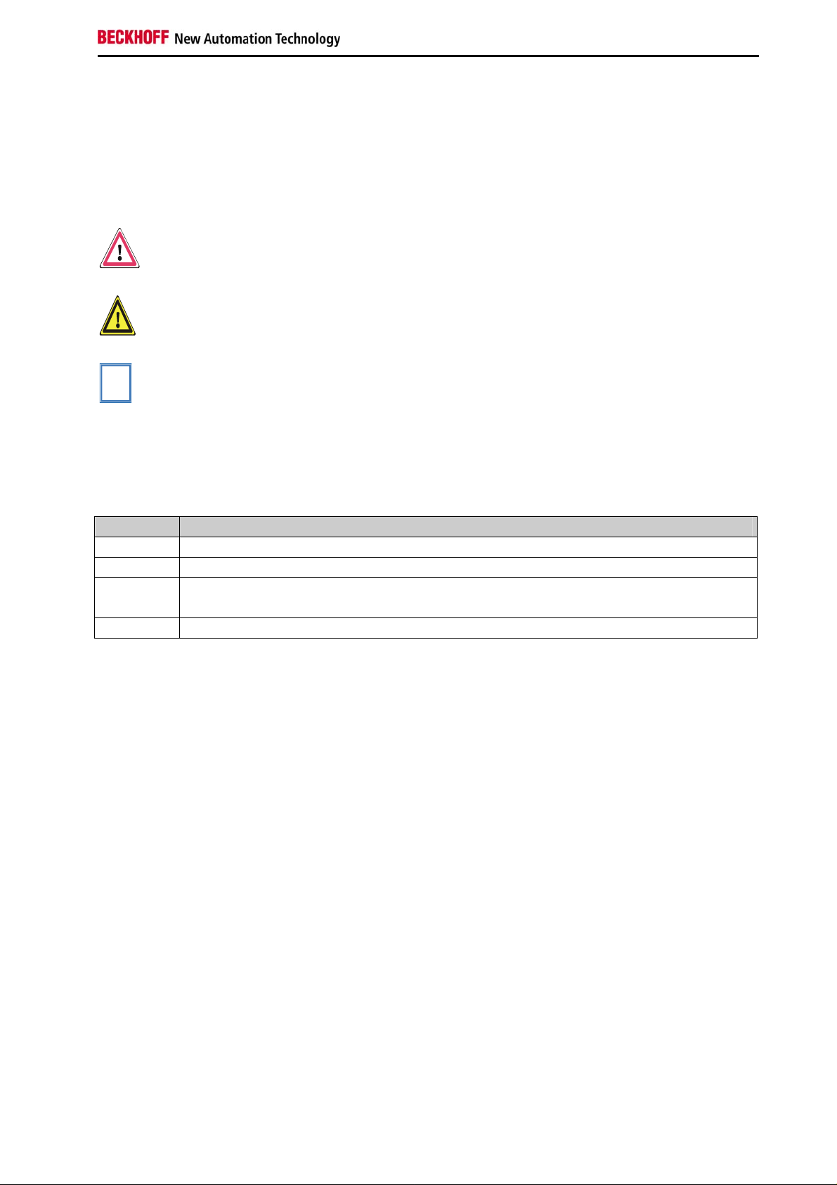
1.1.4 Description of safety symbols
The following safety symbols are used in this operating manual. They are intended to alert the reader to
the associated safety instructions.
i
Danger
Attention
Note
This symbol is intended to highlight risks for the life or health of personnel.
This symbol is intended to highlight risks for equipment, materials or the
environment.
This symbol indicates information that contributes to better understanding.
1.2 Documentation Issue Status
Version Comment
3.0.1 Formal corrections
3.0.0 Description of feature register corrected
2.0 - Technical data updated
- Register description updated
1.0 First release
KL5111-0000 3
Page 6
Product Overview
2 Product Overview
2.1 Technical Data
Technical Data KL5111-0000, KS5111-0000
Sensor connection A, B, C; 24 V
Sensor operating voltage 24 VDC
Counter 16 bits binary
Cut off frequency 1 MHz
Quadrature decoder 4 time evaluation
Zero pulse latch 16 Bit
Commands read, set, activate
Supply voltage 24 VDC (20 ... 29 V)
Current consumption of Power contacts typically 0,1 A (without sensor load current)
Bit width in the process image E/A: 2 x 16 Bit Data, 2 x 8 Bit Control / Status
Current consumption from K-Bus typically 50 mA
Weight app. 60 g
Permissible ambient temperature range
during operation
Permissible ambient temperature range during
storage
Relative humidity 95%, no condensation
Vibration / shock resistance according to EN 60068-2-6 / EN 60068-2-27, EN 60068-2-29
EMC resistance Burst / ESD according to EN 61000-6-2 / EN 61000-6-4
Installation position any
Protection class IP20
Approval CE
0°C ... +55°C
-25°C ... +85°C
4 KL5111-0000
Page 7

Product Overview
2.2 Description of functions
The incremental encoder interface terminal KL5111 enables the connection of any incremental encoders
to the bus coupler or to the controller. The terminal can be operated in two modes (which can be set via
the feature register). The terminal is supplied as an incremental encoder interface. In this mode, the
terminal evaluates the sensor signals A, B, C as a four-fold quadrature decoder. The se nsor is powered
with the available power supply voltage (24 V DC). The KL5111 can also be used as a 16-bit up/down
counter. A period measurement with a resolution of 200 ns of the input A is possible independently of the
set mode.
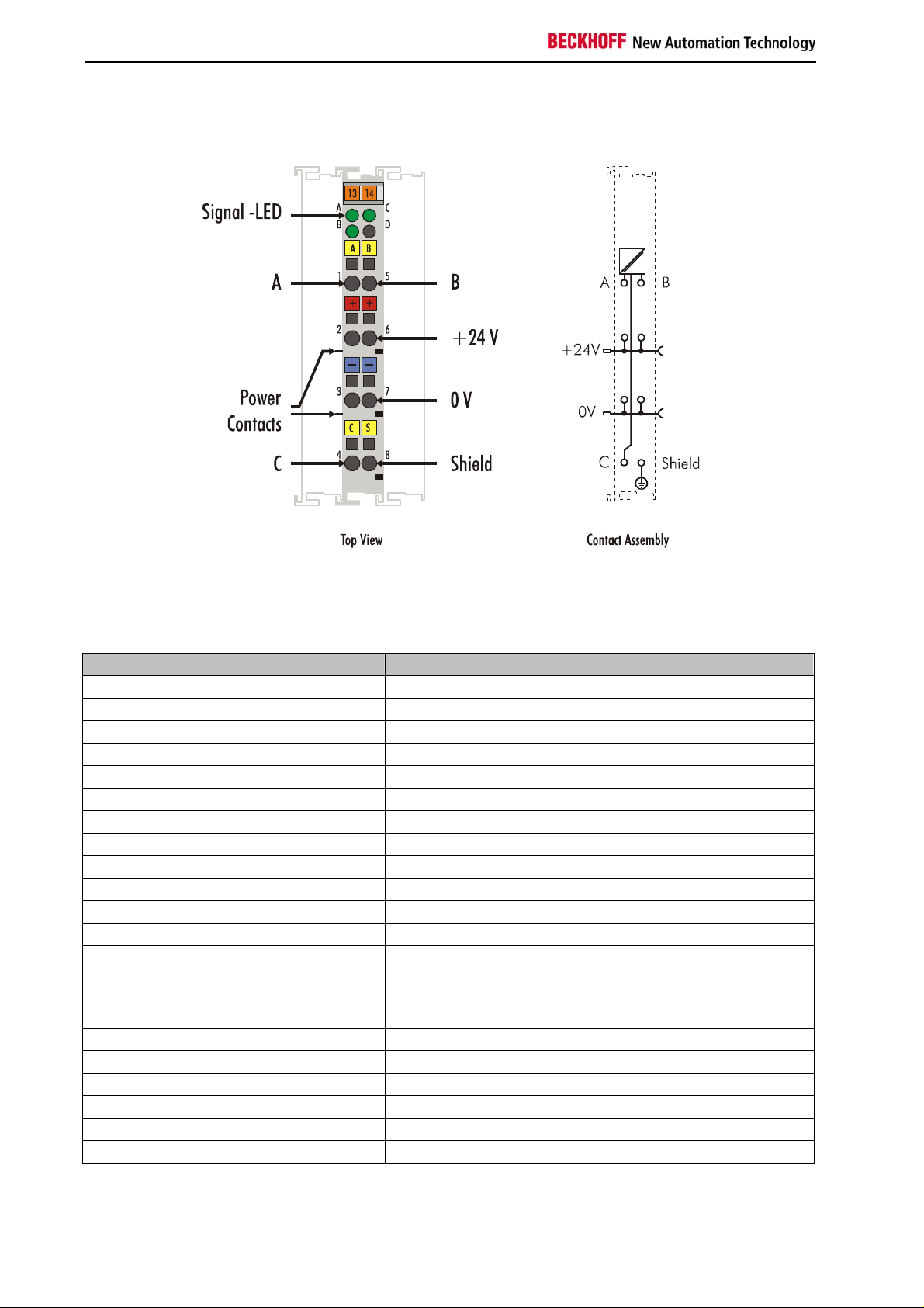
LED display
The signal LEDs indicate the status of the sensor inputs A, B, C. The corresponding LED is activated with
every high signal at the input.
Connections
A, B, zero signals
Shield connection
24 V
power contacts for sensor powering with automatic potential bridging to the neighboring terminal
DC
Operation modes
These can be set via the feature register (default: incremental encoder):
A, B, zero pulse incremental encoder (default)
Up/down counter with:
• A = Count , the positive edges of the input pulses are counted
• B = = Up/down input
B = 0: up counting direction
B = 1: down counting direction
• C = Gate-Eingang
C = 0: counter enabled
C = 1: counter disabled
Functions
• Counting
• Counter setting
• Arming the zero pulse and storing the valid value
• Determining the period between two pulses with a resolution of two 200 ns (the time between two
positive edges of the input signal A is evaluated)
• Indication of the input signals A, B, C, in the process data
• Indication of a counter overflow or underflow.
Process data
The KL5111 occupies 6 bytes of input data and 6 bytes of output data. The control/status byte is at the
least significant byte offset. The data word D0/D1 contains the counter word (read/set) and the data word
D3/D4 contains the latch word (read).
KL5111-0000 5
Page 8

Product Overview
2.3 Terminal configuration
The terminal can be configured and parameterized via the internal register structure.
Each terminal channel is mapped in the bus coupler. The data of the terminal is mapped differently in the
memory of the bus coupler depending on the type of the bus coupler and on the set mapping
configuration (e.g. Motorola/ Intel format, word alignment,...).
Contrary to the analog input and output terminals, in the case of the KL5111 the control and status byte is
always mapped regardless of the higher-level field bus system.
Lightbus Coupler BK2000
In the case of the Lightbus coupler BK2000, the control /status byte is also always (ie. in the case of all
analog terminals) mapped in addition to the data bytes. It is always in the low byte at the offset address of
the terminal channel.
Beckhoff-Lightbus
bus coupler
BK2000
The terminal is
mapped in the
bus coupler.
To the bus terminal
0
K-Bus
Dat H
Data H
D4
-
D1
-
C/S
Data L
C/S
Data L
C/S
D3
D2
D0
C/S
LH
User data allocation depending
on mapping.
Offset Terminal3 Channel1 = 8
Offset Terminal2 Channel2= 6
Offset Terminal2 Channel1= 4
KL5111
Offset Terminal 1= 0
6 KL5111-0000
Page 9

Product Overview
7
PROFIBUS Coupler BK3000
In the case of the PROFIBUS coupler BK3000, the Kl5111 is always mapped with 6 bytes of input data
and 6 bytes of output data.
The control/staus byte
Profibus bus coupler
BK3000
The terminal is
mapped in the
bus coupler.
Data H
Data L
C/S
D3
D4
D2
D0
D1
0
C/S
must be inserted for
parameterization.
Offset Terminal2 Channel1 = 6
The control/status byte will
be inserted for
parameterization (KL5111).
Offset Terminal1= 0
K-Bus
To the bus terminal
Interbus Coupler BK4000
By default, the Interbus coupler BK4000 maps the Kl5111 with 6 bytes of input data and 6 bytes of output
data.
The control/status byte
Interbus bus coupler
BK4000
The terminal is
mapped in the
bus coupler
Nutz H
Nutz L
C/S
D3
D4
D2
D0
D1
0
C/S
must be inserted for
parameterization.
Offset Terminal 2 Channel 1 =
The control/status byte
will be inserted for
parameterization (KL5111).
Offset Terminal 1= 0
K-Bus
To the bus terminal
Other bus couplers and further information
You will find further information on the mapping configuration of bus couplers in the annex of the
respective bus coupler manual and under the heading of Configuration of Masters.
The chapter mapping contains an overview of possible mapping configurations
i
Note
Parameterization with the KS2000 Configuration Software
Independently of the field bus system, parameters can be set via the serial configuration interface in the
bus coupler using the Beckhoff KS2000 configuration software.
KL5111-0000 7
depending on the parameters that can be set.
Page 10

Register description
3 Register description
The complex terminals can be adjusted to different operating modes or functionalities. The general
description of register describes the contents of the registers, which are identical for all complex
terminals.
The terminal-specific registers are explained in the section following to it.
The access to the internal registers of the terminal is described in the section register communication.
3.1 Register Overview
Nr. Description Default value R/W Storage medium
R0
...
R5
R6
R7
R8
R9
R10
R11
R12
R13
R14
R15
R16
R17
...
R30
R31
R32
R33
R34
...
R61
reserved 0x0000 R
... ... ... ...
reserved 0x0000 R
Diagnostic register (not used) 0x0000 R
Command register (not used) 0x0000 R
Terminal type 5111 R ROM
Firmware-Version 0x???? R ROM
Multiplex shift register 0x0218 R ROM
Signal channels 0x0130 R ROM
minimum data length 0x3030 R ROM
Data structure 0x0000 R ROM
reserved 0x0000 R
Alignment register variable R/W RAM
Hardware version 0x???? R/W SEEROM
reserved 0x0000 R/W SEEROM
... ... ... ...
reserved 0x0000 R/W SEEROM
Code word register variable R/W RAM
Feature register 0x0000 R/W SEEROM
Time window for frequency
measurement
reserved 0x0000 R/W SEEROM
... ... ... ...
reserved 0x0000 R/W SEEROM
0x0000 R/W SEEROM
8 KL5111-0000
Page 11

Register description
3.2 General register description
Complex terminals that possess a processor are capable of bidirectionally ex-changing data with the
higher-level control system. Below, these terminals are referred to as intelligent bus terminals. They
include the analog inputs (0 to 10V, -10 to 10V, 0 to 20mA, 4 to 20mA), the analog outputs
(0 to 10V, -10 to 10V, 0 to 20mA, 4 to 20mA), serial interface terminals (RS485, RS232, TTY, data
transfer terminals), counter terminals, encoder interfaces, SSI interfaces, PWM terminals and all other
parameterizable terminals.
Internally, all intelligent terminals possess a data structure that is identical in terms of it's essential
characteristics. This data area is organized in words and embraces 64 memory locations. The essential
data and parameters of the terminal can be read and adjusted by way of the structure. Function calls with
corresponding parameters are also possible. Each logical channel of an intelligent terminal has such a
structure (therefore, 4-channel analog terminals have 4 register sets.
This structure is broken down into the following areas:
Area Register number
Process variables 0 to 7
Type registers 8 to 15
Manufacturer parameters 16 to 30
User parameters 31 to 47
Extended user area 48 to 63
3.2.1 Process variables
R0 to R7: Registers in the terminal’s internal RAM
The process variables can be used in additional to the actual process image and their functions are
specific to the terminal.
R0 to R5: These registers have a function that depends on the terminal type.
R6: Diagnostic register
The diagnostic register may contain additional diagnostic information. In the case of serial interface
terminals, for example, parity errors that have occurred during data transfer are indicated.
R7: Command register
High-Byte_Write = function parameter
Low-Byte_Write = function number
High-Byte_Read = function result
Low-Byte_Read = function number
3.2.1.1 R8 to R15 Registers in the terminal’s internal ROM
The type and system parameters are programmed permanently by the manufacturer and can only be
read by the user but cannot be modified.
R8: Terminal type:
The terminal type in register R8 is needed to identify the terminal.
R9: Firmware Version X.y
The Firmware-Version can be read as an ASCII character string.
KL5111-0000 9
Page 12

Register description
R10: Data length
R10 contains the number of multiplexed shift registers and their length in bits. The bus coupler sees this
structure.
R11: Signal channels
In comparison with R10, the number of logically existing channels is located here. For example, one
physically existing shift register may consist of several signal channels.
R12: Minimum data length
The respective byte contains the minimum data length of a channel to be transferred. If the MSB is set,
then the control/status byte is not necessarily needed for the function of the terminal and, with appropriate
configuration of the coupler, is not transferred to the control system.
R13: Data type register
Data type Description
0x00 Terminal without valid data type
0x01 Byte array
0x02 Structure 1 Byte, n Bytes
0x03 Word array
0x04 Structure 1 Byte, n Words
0x05 Double word array
0x06 Structure 1 Byte, n Double words
0x07 Structure 1 Byte, 1 Double word
0x08 Structure 1 Byte, 1 Double word
0x11 Byte a with a variable logical channel length
0x12 Structure 1 Byte, n Bytes with variable logical channel length (e.g. 60xx)
0x13 Word-Array with a variable logical channel length
0x14 Structure 1 Byte, n Words with a variable logical channel length
0x15 Double word -Array with a variable logical channel length
0x16 Structure 1 Byte, n Double words with a variable logical channel length
R14: not used
R15: Alignment-Bits (RAM)
The analog terminal is set to a byte limit in the terminal bus with the alignment bits.
10 KL5111-0000
Page 13

Register description
3.2.2 Manufacturer Parameters
3.2.2.1 R16 to R30: Manufacturer Parameters (SEEROM)
The manufacturer parameters are specific to each terminal type. They are programmed by the
manufacturer but can also be modified from the control system. The manufacturer parameters are stored
permanently in a serial EEPROM and are therefore not destroyed by power failures.
These registers can only be modified after setting a code word in R31.
3.2.3 User Parameters
3.2.3.1 R31 to R47 User Parameters (SEEROM)
The application parameters are specific to each terminal type. They can be modified by the programmer.
The application parameters are stored permanently in a serial EEPROM in the termin al and cannot be
destroyed by power failures. The user area is write protected over a Codeword.
R31: Code Word-Register in the RAM
The code word 0x1235 must be entered here to enable modification of parameters
i
Note
R32: Feature-Register
This register defines the operating modes of the terminal. For example, a user-specific scaling ca n be
activated for the analog I/Os.
3.2.3.2 R33 to R47
Registers that depend on the terminal type.
in the user area. Write-protection is set if a different value is entered in this register.
When write protection is inactive, the code word is returned during readi ng of the
register. The register contains the value zero when write protection is active.
KL5111-0000 11
Page 14

Register description
3.3 Terminal-specific register description
3.3.1 Application parameters
R32: Feature Register
The feature register determines the operating modes of the terminal (default . 0x0000).
Bit Value Description default
R32.15
R32.14
...
R32.9
R32.8
R32.7
...
R32.1
R32.0
0
Encoder interface is activated
bin
1
Counter mode is activated
bin
16-bit up/down counter
Input A: counter
Input B: counting direction (high = down, low = up)
Input C: high = counter disabled, low = counter enabled
- reserved 0
... ... ...
- reserved 0
0
Period time is measured if bit CB.1 of control byte is set
bin
1
In place of the period time a frequency measurement is executed. Impulses in
bin
a time window are counted. The time window is over R33 adjustable.
- reserved 0
... ... ...
- reserved 0
0
the underflow/overflow signals are output in the status byte.
bin
1
The signals A; B, C are output in the terminal's status byte.
bin
0
bin
bin
bin
0
bin
bin
bin
0
bin
R33: Time window for frequency measurement
Defines the length of the time window for frequency measurement (default: 0x0000).
Resolution: 1 ms/Digit
1 Digit = 1 ms
The measured frequency is displayed in process data bytes D3 and D4.
The process data bytes D3 and D4 show the number of pulses counted within the time window defined by
R32. The frequency can be calculated from this.
Please note that bit CB.1 of control byte has also to be set for frequency
i
Note
measurement!
12 KL5111-0000
Page 15

Register description
3.4 Control and Status Byte
3.4.1 Process data exchange
3.4.1.1 Control-Byte during process data exchange
The control byte is transferred from the controller to the terminal. It can be used in the register mode
(RegAcc = 1) or during process data exchange (RegAcc=0). Variou s actions are triggered in the KL5111
with the control byte:
Bit
Name
Bit Name Function
CB.7 RegAcc=0 Process data exchange
CB.6 - reserved
... ... ...
CB.3 - reserved
CB.2 Cnt_Set The counter is set with a rising edge of Cnt_Set to the value that is specified via the
CB.1 RD-Period If CB.1 is set and Bit R32.8 of Feature Register is not set:
CB.0 En_Latch The zero point latch (C input) is activated. With the first external latch pulse after
CB.7 CB.6 CB.5 CB.4 CB.3 CB.2 CB.1 CB.0
RegAcc - - - - Cnt_Set RD-Period En_Latch
process data.
The periods between two positive edges of the input A are measured with a
resolution of 200 ns and displayed at data bytes DataIN2, DataIN3 and DataIN4.
If CB.1 and Bit R32.8 of Feature Register is set:
The pulses within a time window defined by R33 are counted and displayed at data
bytes DataIN3 and DataIN4.
the validity of the En_Latch bit, the counter value is stored in the latch register (this
has priority over En_LatchX). The following pulses have no influence on the latch
register when the bit is set (not used if the V/R mode is active, i.e. bit 15 is set in
the feature register).
3.4.1.2 Status-Byte during process data exchange
The status byte is transferred from the terminal to the controller. The status byte contains various status
bits of the KL5101.
Remark: the signal bits A, B, C are output in the data byte D2 (bits 3, 4, 5)
Bit
Name
KL5111-0000 13
CB.7 CB.6 CB.5 CB.4 CB.3 CB.2 CB.1 CB.0
RegAcc - - Overflow Underflow CntSet_Acc RD_Period_Q Latch_Val
Page 16

Register description
Bit Name Function
SB.7 RegAcc=0 Acknowledge for process data exchange
SB.6 - reserved
SB.5 - reserved
SB.4 Overflow This bit is set if an overflow (65535 to 0) of the 16-bit counter occurs.
It is reset if the counter exceeds a third of the measurement range
(21845 to 21846) or as soon as an underflow occurs.
SB.3 Underflow This bit is set if an underflow (0 to 65535) of the 16-bit counter
occurs. It is reset when the counter drops below two thirdds of the
measurement range (43690 to 43689) or as soon as an overflow
occurs.
SB.2 CntSet_Acc The data for setting the counter has been accepted from the terminal.
SB.1 RD_Period_Q if bit R32.8 of Feature Register is not set:
Die data bytes DataIN2, DataIN3 and DataIN4 contain the period
if bit R32.8 8 of Feature Register is set:
DataIN3 und DataIN4 contain the counted pulses
SB.0 Latch_Val A zero point latch has occurred. The data DIN3, DIN4 in the process
image corresponds to the latched value when the bit is set if the
period has not been requested. To reactivate the latch input,
EN_LATC must first be cancelled, acknowledgement of cancellation
must be waited for and then the bit must be set again. (Not used if
the V/R mode is active, i.e. bit 15 is set in the feature register).
or if bit 0 is set in the feature register:
Bit
Name
CB.7 CB.6 CB.5 CB.4 CB.3 CB.2 CB.1 CB.0
RegAcc - A-Signal B-Signal C-Signal CntSet_Acc RD_Period_Q Latch_Val
Bit Name Function
SB.7 RegAcc=0 Acknowledge for process data exchange
SB.6 - reserved
SB.5 A-Signal status of the input A
SB.4 B-Signal status of the input B
SB.3 C-Signal status of the input C
SB.2 CntSet_Acc The data for setting the counter has been accepted from the terminal.
SB.1 RD_Period_Q if bit R32.8 of Feature Register is not set:
Die data bytes DataIN2, DataIN3 and DataIN4 contain the period
if bit R32.8 8 of Feature Register is set:
DataIN3 und DataIN4 contain the counted pulses
SB.0 Latch_Val A zero point latch has occurred. The data DataIN3, DataIN4 in the
process image corresponds to the latched value when the bit is set if
the period has not been requested. To reactivate the latch input,
EN_LATC must first be cancelled, acknowledgement of cancellation
must be waited for and then the bit must be set again. (Not used if
the V/R mode is active, i.e. bit 15 is set in the feature register).
14 KL5111-0000
Page 17

Register description
3.4.2 Register Communication
When bit 7 of the control byte is set, the first two bytes of the user data are not used for process data
transfer, but are written into or read out of the terminal’s register.
In bit 6 of the control byte, you define whether a register is to be read or written. When bit 6 is not set, a
register is read without modification. The value can be taken from the input process image.
When bit 6 is set, the user data is written into a register. The operation is concluded as soon as the status
byte in the input process image has supplied an acknowledgement (see examples).
The address of the register to be addressed is entered in bits 0 to 5 of the control byte.
3.4.2.1 Control byte during Register Communication
Bit
Name
CB.7 CB.6 CB.5 CB.4 CB.3 CB.2 CB.1 CB.0
RegAcc R/W Reg-No.
Bit Name Function
CB.7 RegAcc=1 Register Communication
CB.6 R/W Bit 6=0: read, Bit 6=1: write
CB.5
Reg-No. Register number of the register that is to be read or written
...
CB.0
3.4.2.2 Status byte during Register Communication
Bit
Name
SB.7 SB.6 SB.5 SB.4 SB.3 SB.2 SB.1 SB.0
RegAcc R/W Reg-No.
Bit Name Function
CB.7 RegAcc=1 acknowledge for Register Communication
CB.6 R/W Bit 6=0: read
CB.5
Reg-No. Register number of the register that has been read or written
...
CB.0
KL5111-0000 15
Page 18

Register description
3.4.3 Examples for the Register Communication
To the bus coupler
K-Bus
Control-/
status byte
C/S-bit 7
User data
2 or mors bytes
H
L
If contr ol bit 7=0: input/output
If contr ol bit 7=1 :
registerconfiguration
0
If control bit 7=1:
adress in the control bit 0-5
If contr ol bit 6=0: r e a d
If control bit 6=1: write
Terminal´s
register set
64 words
Complex bus te rmina l
63
H
L
The control or status byte occupies the lowest address of a logical channel. The corresponding register
values are located in the following 2 data bytes (the BK2000 is an exception to the rule: here, an unused
data byte is inserted after the control or status byte, thus setting the register value to a word limit).
Example 1
Reading register 8 in the BK2000 with a Kl3002 and the end terminal.
If the following bytes are transferred from the controller to the terminal,
Byte
Byte 3 Byte 2 Byte 1 Byte 0
Name DataOUT 1 DataOUT 0 Nicht benutzt Control-Byte
Wert 0xXX 0xXX 0xXX 0x88
the terminal returns the following type designation (0x0BBA corresponds to the unsigned integer 3002).
Byte
Name
Wert
Byte 3 Byte 2 Byte 1 Byte 0
DataIN 1 DataIN 0 Nicht benutzt Status-Byte
0x0B 0xBA 0x00 0x88
16 KL5111-0000
Page 19

Register description
Example 2
Writing register 31 in the BK2000 with an intelligent terminal and the end terminal.
If the following bytes (user code word) are transferred from the controller to the terminal,
Byte
Name
Wert
Byte 3 Byte 2 Byte 1 Byte 0
DataOUT 1 DataOUT 0 Nicht benutzt Control-Byte
0x12 0x35 0xXX 0xDF
the user code word is set and the terminal returns the register address with the bit 7 for register access
and the acknowledgement.
Byte
Name
Wert
Byte 3 Byte 2 Byte 1 Byte 0
DataIN 1 DataIN 0 Nicht benutzt Status-Byte
0x00 0x00 0x00 0x9F
KL5111-0000 17
Page 20

Register description
3.5 Mapping in the bus coupler
As already described in the Terminal Configuration section, each Bus Terminal is mapped in the Bus
Coupler. In the delivery state, this mapping occurs with the default settings of the Bus Coupler for this
terminal. The default setting can be changed with the KS2000 configuration software or with a maste r
configuration software (e.g. TwinCAT System Manager or ComProfibus).
The KL5111 occupies memory space in the input and output process image. The following tables provide
information about the KL5111’s mapping, depending on the conditions set in the Bus Coupler.
Default mapping for
CANopen, CANCAL, DeviceNet, ControlNet, Modbus, RS232 und RS485 Couplers
Conditions
Complete evaluation: any
Motorola format: no
Word alignment: no
Default mapping for Profibus and Interbus Couplers
Conditions
Complete evaluation: any
Motorola format: yes
Word alignment: no
Default mapping for
EtherCAT, Lightbus and Ethernet Couplers and Bus Terminal Controllers (BCxxxx, BXxxxx)
Conditions
Complete evaluation: any
Motorola format: no
Word alignment: yes
Word Offset High byte Low byte
0 D0 CB/SB
1 D2 D1
2 D4 D3
Word offset High byte Low byte
0 D1 CB/SB
1 D2 D0
2 D3 D4
Word offset High byte Low byte
0 - CB/SB
1 D1 D0
2 - D2
3 D4 D3
Conditions
Complete evaluation: any
Motorola format: yes
Word alignment: yes
Word offset High byte Low byte
0 - CB/SB
1 D0 D1
2 - D2
3 D3 D4
Key
Complete evaluation: The terminal is mapped with control and status byte.
Motorola format: Motorola or Intel format can be set.
Word alignment: The terminal is at word limit in the Bus Coupler.
CB: Control Byte (appears in the output process image)
SB: Status Byte (appears in the input process image)
D0: byte of the Counter Word with the lowest value (read /set)
D1: byte of the Counter Word with the highest value (read /set)
D2: together with D3/D4 this byte contains the cycle duration
D3: byte of the Latch Word with the lowest value (read)
D4: byte of the Latch Word with the highest value (read)
18 KL5111-0000
Page 21

Appendix
4 Appendix
4.1 Support and Service
Beckhoff and their partners around the world offer comprehensive support and service, making available
fast and competent assistance with all questions related to Beckhoff products and system solutions.
4.1.1 Beckhoff's branch offices and representatives
Please contact your Beckhoff branch office or representative for local support and service on Beckhoff
products!
The addresses of Beckhoff's branch offices and representatives round the world can be found on her
internet pages: http://www.beckhoff.com
You will also find further documentation for Beckhoff components there.
4.2 Beckhoff Headquarters
Beckhoff Automation GmbH
Eiserstr. 5
33415 Verl
Germany
phone: + 49 (0) 5246/963-0
fax: + 49 (0) 5246/963-198
e-mail: info@beckhoff.com
web: www.beckhoff.com
Beckhoff Support
Support offers you comprehensive technical assistance, helping you no only with the application of
individual Beckhoff products, but also with other, wide-ranging services:
• support
• design, programming and commissioning of complex automation systems
• and extensive training program for Beckhoff system components
hotline: + 49 (0) 5246/963-157
fax: + 49 (0) 5246/963-9157
e-mail: support@beckhoff.com
Beckhoff Service
The Beckhoff Service Center supports you in all matters of after-sales service:
• on-site service
• repair service
• spare parts service
• hotline service
hotline: + 49 (0) 5246/963-460
fax: + 49 (0) 5246/963-479
e-mail: service@beckhoff.com
KL5111-0000 19
 Loading...