

Page 1
Documentation for
KL3064
4-Channel Analog Input Terminal 0...10 V
Version: 2.2
Date: 2013-04-03
Page 2

Contents
Contents
1. Foreword 3
Notes on the documentation 3
Safety Instructions 4
2. Technical data 5
3. ATEX - Special conditions 6
4. Description of functions 7
5. Terminal configuration 8
6. Register description 10
General register description 10
Terminal-specific register description 12
Control/Status byte 14
Register communication KL3064 15
7. Annex 17
Mapping in the bus coupler 17
Table of the register 19
8. Appendix 20
Support and Service 20
Beckhoff Headquarters 20
2 KL3064
Page 3

Foreword
Foreword
Notes on the documentation
This description is only intended for the use of trained specialists in control and automation engineering
who are familiar with the applicable national standards. It is essential that the following notes and explanations are followed when installing and commissioning these component s.
The responsible staff must ensure that the application or use of the products described satisfy all the requirements for safety, including all the relevant laws, regulations, guidelines and standards.
Disclaimer
The documentation has been prepared with care. The products described are, however, constantly under
development. For that reason the documentation is not in every case checked for consistency with performance data, standards or other characteristics. In the event that it contains technical or editorial errors,
we retain the right to make alterations at any time and without warning. No claims for the modification of
products that have already been supplied may be made on the basis of the data, diagrams and descriptions in this documentation.
Delivery conditions
In addition, the general delivery conditions of the company Beckhoff Automation GmbH apply.
Trademarks
Beckhoff
trademarks of and licensed by Beckhoff Automation GmbH. Other designations used in this publication
may be trademarks whose use by third parties for their own purposes could violate the rights of the owners.
Patent Pending
The TwinCAT Technology is covered, including but not limited to the following patent applications and
patents: EP0851348, US6167425 with corresponding applications or registrations in various other countries.
Copyright
© Beckhoff Automation GmbH
The reproduction, distribution and utilization of this document as well as the communication of its contents
to others without express authorization are prohibited. Offenders will be held liable for the payment of
damages. All rights reserved in the event of the grant of a patent, utility model or design.
®
, TwinCAT®, EtherCAT®, Safety over EtherCAT®, TwinSAFE®, XFC® and XTS® are registered
KL3064 3
Page 4
Foreword
Safety Instructions
State at Delivery
All the components are supplied in particular hardware and software configurations appropriate for the
application. Modifications to hardware or software configurations other than those described in the documentation are not permitted, and nullify the liability of Beckhoff Automation GmbH.
Description of safety symbols
The following safety symbols are used in this documentation. They are intended to alert the reader to the
associated safety instructions..
Serious risk of injury!
DANGER
Failure to follow the safety instructions associated with this symbol directly endangers
the life and health of persons.
Danger for persons!
CAUTION
Note
Failure to follow the safety instructions associated with this symbol may endanger
persons.
Tip or pointer
This symbol indicates information that contributes to better understanding.
4 KL3064
Page 5
Technical data
Technical data
Technical data KL3064
Number of inputs 4 (single ended)
Power supply via the K-Bus
Signal voltage 0 ... 10 V
Internal resistance
Resolution 12 bits
Conversion time app. 4 ms
Measuring error (total measuring range) < ± 0.30% (at 0°C ... +55°C)
Electrical isolation 500 V (K-Bus / signal voltage)
Current consumption 85 mA typ.
Bit width in the process image input: 4 x 16 bits (4 x 8 bits control/status optional)
Configuration no address or configuration setting
Weight approx. 80 g
Operating temperature -25°C ... +60°C in operation (extended temperature range)
Storage temperature -40°C... +85°C
Relative humidity 95%, no condensation
Vibration/shock resistance conforms to EN 60068-2-6/EN 60068-2-27
EMC immunity/emmission conforms to EN 61000-6-2/EN 61000-6-4
Installation position variable
Type of protection IP20
Approvals CE, cULus, ATEX, GL
> 130 kΩ
< ± 0.75% (at utilization of the extended temperature range)
0°C ... +55°C (according to cULus for Canada and USA)
0°C ... +55°C (according to ATEX, see special conditions)
KL3064 5
Page 6
ATEX - Special conditions
ATEX - Special conditions
Observe the special conditions for the intended use of
Beckhoff fieldbus components in potentially explosive areas (directive 94/9/EU)!
WARNING
• The certified components are to be installed in a suitable housing that guaran-
tees a protection class of at least IP54 in accordance with EN 60529! The environmental conditions during use are thereby to be taken into account!
• If the temperatures during rated operation are higher than 70°C at the feed-in
points of cables, lines or pipes, or higher than 80°C at the wire branching
points, then cables must be selected whose temperature data correspond to
the actual measured temperature values!
• Observe the permissible ambient temperature range of 0 - 55°C for the use of
Beckhoff fieldbus components in potentially explosive areas!
• Measures must be taken to protect against the rated operating voltage being
exceeded by more than 40% due to short-term interference voltages!
• The individual terminals may only be unplugged or removed from the Bus
Terminal system if the supply voltage has been switched off or if a nonexplosive atmosphere is ensured!
• The connections of the certified components may only be connected or dis-
connected if the supply voltage has been switched off or if a non-explosive atmosphere is ensured!
• The fuses of the KL92xx power feed terminals may only be exchanged if the
supply voltage has been switched off or if a non-explosive atmosphere is ensured!
• Address selectors and ID switches may only be adjusted if the supply voltage
has been switched off or if a non-explosive atmosphere is ensured!
Operation of the Bus Terminal System in potentially explosive areas (ATEX)!
Note
Pay also attention to the continuative documentation
Notes about operation of the Bus Terminal System in potentially explosive areas
(ATEX)
that is available in the download area
http://www.beckhoff.com
!
of the Beckhoff homepage
6 KL3064
Page 7

Description of functions
Description of functions
The analog input terminal KL3064 processes signals within the range from
0 to +10V with a resolution of 12 bits (4095 increments). The inputs of the
KL3064 consist of single ended inputs with a common earth potential.
Output format
of process data
In the default setting, process data is represented in the twos complement
(integer -1 corresponds to 0xFFFF). By way of the feature register, other
modes of representation can be selected (eg.signed amount representation, Siemens output format).
Measured value Decimal output Hexadecimal output
0V
0 0x0000
5V
16383 0x3FFF
10V
32767 0x7FFF
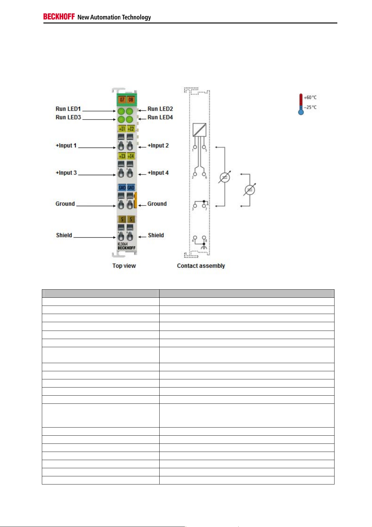
LED display
The four RUN LEDs indicate the operating state of the affiliated terminal
channel.
RUN LED:
On – normal opeation
Off – a watchdog-timer overflow has occurred. The green LEDs go off if no
process data is transferred by the bus coupler for 100 ms.
Process data
The process data that is transferred to the bus coupler is calculated on the
basis of the following equations:
X_adc: AD convertor output values
Y_aus : Process data to the PLC
B_a,A_a : Manufacturer gain und offset adjustment (R17,R18)
B_h,A_h : Manufacturer scaling (R19,R20)
B_w,A_w : User scaling (R33,R34)
a) neither user nor manufacturer scaling active:
Y_a = (B_a+X_adc)* A_a (1.0)
Y_aus =Y_a
b) Manufacturer scaling active: (default)
Y_1 =B_h + A_h * Y_a (1.1)
Y_aus= Y_1
c) User scaling active:
Y_2 =B_w + A_w * Y_a (1.2)
Y_aus= Y_2
d) Manufacturer and user scaling active:
Y_1 = B_h + A_h * Y_a (1.3)
Y_2 =B_w + A_w * Y_1 (1.4)
Y_aus = Y_2
The straight-line equations are activated by means of R32.
KL3064 7
Page 8

Terminal configuration
Beckhoff Lightbus
Coupler BK2000
Terminal configuration
The terminal can be configured and parametrized by way of the internal
register structure.
Each terminal channel is mapped in the bus coupler. The terminal’s data is
mapped differently in the bus coupler’s memory depending on the type of
the bus coupler and on the set mapping configuration (eg.Motorola / Intel
format, word alignment,...). For parametrization of a terminal, the control
/status byte must also be mapped.
In the case of the Beckhoff Lightbus coupler BK2000, the control /status
byte is always mapped besides the data bytes. It is always in the low byte
at the offset address of the terminal channel.
amount rep.
add. bits
user scalingmanuf. scal.Gain, Offset adjust.
Profibus Coupler BK3000
Beckhoff-Lightbus
User dat allocation depending
on mapping
bus coupler
BK2000
The terminal is
mapped in the
bus coupler.
C/S
D1 - 3
D1 -20
D1 - 1
D1 - 0
0 Offset Terminal1 Channel1 = 0
D0 - 3
C/S - 1
D0 - 2
C/S - 0
D0 - 1
C/S - 1
D0 - 0
C/S - 0
Offset Terminal2 Channel1 = 8
KL3064, Channel 3 + 4
Offset Terminal1 Channel3 = 4
KL3064, Channel 1 + 2
LH
K-Bus
To the bus terminal
In the case of the Profibus coupler BK3000, for which terminal channels
the control /status byte is also to be inserted must be defined in the master
configuration .If the control /status byte is not evaluated, the KL3064 occupies 8 bytes of input data (2 bytes of user data per channel).
8 KL3064
Page 9

Terminal configuration
Interbus Coupler BK4000
The control/staus byte
must be inserted for
parameterization.
Profibus bus coupler
BK3000
The terminal is
mapped in the
bus coupler
D0 - 3
D1 - 3
C/S - 3
D0 - 2
D1 - 2
C/S - 2
D0 - 1
D1 - 1
C/S - 1
D0 - 0
D1 - 0
C/S - 0
0
KL3064 Channel 4
Offset Terminal1 Channel3 = 9
KL3064 Channel 3
Offset Terminal1 Channel3 = 6
KL3064 Channel2
Offset Terminal1 Channel2 = 3
KL3064 Channel1
Offset Terminal1 Channel1 = 0
K-Bus
To the bus terminal
By default, the Interbus coupler BK4000 maps the KL3064 with 8 bytes of
input data (2 bytes of user data per channel). Parametrization via the field
bus is not possible. The KS2000 software is required for configuration if
use is to be made of the control /status byte.
Interbus bus coupler
BK4000
The terminal is
mapped in the
bus coupler
D0 - 3
D1 - 3
D0 - 2
D1 - 2
D0 - 1
D1 - 1
D0 - 0
D1 - 0
0
The control/status byte
must be inserted for
parameterization (KS2000).
Offset Terminal1 Channel4 = 6
Offset Termianl1 Channel3 = 4
Offset Terminal1 Channel2 = 2
Offset Terminal1 Channel1 = 0
K-Bus
To the bus terminal
Other bus couplers and
further information
i
Note
Parametrization with the
KS2000 software
KL3064 9
You will find further information on the mapping configuration of bus couplers in the annex of the respective bus coupler manual under the heading
of "Configuration of masters".
The annex contains an overview of the possible mapping configurations
depending on the adjustable parameters.
Parametrization operations can be carried out independantly of the field
bus system using the Beckhoff KS2000 configuration software via the serial configuration interface in the bus coupler.
Page 10

Register description
Register description
Process variables R0 - R7: Registers in the terminal’s internal RAM:
The complex terminals can be adjusted to different operating modes or
functionalities. The " general description of register " describes the contents of the registers, which are identical for all complex terminals.
The terminal-specific registers are explained in the section following to it.
The access to the internal registers of the terminal is described in the sec-
tion " register communication ".
General register description
Complex terminals that possess a processor are capable of bidirectionally
ex-changing data with the higher-level control system. Below, these terminals are referred to as intelligent bus terminals. They include the analog
inputs (0-10V, -10-10V, 0-20mA, 4-20mA), the analog outputs (0-10V, -1010V, 0-20mA, 4-20mA), serial interface terminals (RS485, RS232, TTY,
data transfer terminals), counter terminals, encoder interfaces, SSI interfaces, PWM terminals and all other parametrizable terminals.
Internally, all intelligent terminals possess a data structure that is identical
in terms of it's essential characteristics. This data area is organized in
words and embraces 64 memory locations. The essential data and parameters of the terminal can be read and adjusted by way of the structure.
Function calls with corresponding parameters are also possible. Each logical channel of an intelligent terminal has such a structure (therefore, 4channel analog terminals have 4 register sets.
This structure is broken down into the following areas:
(You will find a list of all registers at the end of this documentation).
Area Address
Process variables
Type registers
Manufacturer parameters
User parameters
Extended user area
The process variables can be used in additional to the actual process image and their functions are specific to the terminal.
R0 - R5: These registers have a function that depends on the terminal
type.
R6: Diagnostic register
The diagnostic register may contain additional diagnostic information. In
the case of serial interface terminals, for example, parity errors that have
occurred during data transfer are indicated.
R7: Command register
High-Byte_Write = function parameter
Low-Byte _Write = function number
High-Byte _Read = function result
Low-Byte_ Read = function number
0-7
8-15
16-30
31-47
48-63
10 KL3064
Page 11

Register description
Type registers R8 - R15 Registers in the terminal’s internal ROM der Klemme
The type and system parameters are programmed permanently by the
manufacturer and can only be read by the user but cannot be modified.
R8: Terminal type:
The terminal type in register R8 is needed to identify the terminal.
R9: Software version X.y
The software version can be read as an ASCII character string.
R10: Data length
R10 contains the number of multiplexed shift registers and their length in
bits.
The bus coupler sees this structure.
R11: Signal channels
In comparison with R10, the number of logically existing channels is located here. For example, one physically existing shift register may consist
of several signal channels.
R12: Minimum data length
The respective byte contains the minimum data length of a channel to be
transferred. If the MSB is set, then the control/status byte is not necessarily
needed for the function of the terminal and, with appropriate configuration
of the coupler, is not transferred to the control system.
R13: Data type register
Data type register
0x00
0x01
0x02
0x03
0x04
0x05
0x06
0x07
0x08
0x11
0x12 1 byte n bytes structure with a variable logical channel
0x13
0x14 1 byte n words structure with a variable logical channel
0x15
0x16 1 byte n double words structure with a variable logical
Terminal without valid data type
Byte array
1 byte n bytes structure
Word array
1 byte n words structure
Double word array
1 byte n double words structure
1 byte 1 double word structure
1 byte 1 double word structure
Byte-array with a variable logical channel length
length (eg 60xx)
Word-array with a variable logical channel length
length
Double word array with a variable logical channel length
channel length
R14: not used
R15: Alignment bits (RAM)
The analog terminal is set to a byte limit in the terminal bus with the alignment bits.
Manufacturer parameters R16 - R30 is the area of the "Manufacturer parameters" (SEEROM)
The manufacturer parameters are specific to each terminal type. They are
programmed by the manufacturer but can also be modified from the control
system. The manufacturer parameters are stored permanently in a serial
EEPROM and are therefore not destroyed by power failures.
These registers can only be modified after setting a code word in R31.
KL3064
11
Page 12

Register description
User parameters
i
Note
Extended application area R47 - R63
Process variables R0: Raw ADC value X_R
Manufacturer's Parameters R17: Offset – Hardware B_a
12 KL3064
R31 - R47 "Application parameters" area (SEEROM)
The application parameters are specific to each terminal type. They can be
modified by the programmer. The application parameters are stored permanently in a serial EEPROM in the terminal and cannot be destroyed by
power failures. The user area is write protected over a Codeword.
R31: Code word-register in the RAM
The code word 0x1235 must be entered here to enable modification of
parameters in the user area. Write-protection is set if a different value is
entered in this register. When write protection is inactive, the code word is
returned during reading of the register. The register contains the value zero
when write protection is active.
R32: Feature-register
This register defines the operating modes of the terminal. For example, a
user-specific scaling can be activated for the analog I/O’s.
R33 - R47
Registers that depend on the terminal type
These registers have not yet been implemented.
Terminal-specific register description
This register contains the ADC raw value afflicted with gain and offset errors.
R1 - R5: No function
R6: Diagnostic register
High byte: not used
Low byte: status byte
16 bit signed integer
The terminal’s offset is adjusted via this register (Eq. 1.1).
Register value approximately 0xFFXX
R18: Gain-Hardware A_a
16 bit * 2 ^-12
The terminal’s gain is adjusted by means of this register (Eq. 1.1).
In doing so a 1 corresponds to 0x1000.
Register value approximately 0x11XX
R19: Manufacturer –Offset B_h
16 bit signed integer [0x0000]
This register contains the offset of the manufacturer‘s straight-line equation
(1.3). The straight-line equation is activiated via R32.
R20: Manufacturer scaling A_h
16 bit signed integer *2^-10 [0x2002]
This register contains the scaling factor of the manufacturer’s straight-line
equation (1.3). The straight-line equation is activated via R32.
A 1 corresponds to the register value 0x0400.
R21: Over range limit: OVRL
16 bit signed integer in Y_a Gl 1.0 [0x0FFF]
This limit limits the maximum measured range of the input terminal. If it is
exceeded, the corresponding status bit is set and the maximum value is
Page 13

Register description
output.
R22: Under range limit: UNRL
16 bit signed integer in Y_a Gl.1.0 [0x0000]
If the actual value drops below this limit, the corresponding status bit is set
and the minimum value is output.
R23: ADC-Hardware preset
[0x1000]
Initialization of the ADC offset register.
Application parameters R32: Feature register:
[0x1106]
The feature register determines the operating modes of the terminal.
Feature Bit No. Mode description
Bit 0
Bit 1
Bit 2
Bit 3
Bit 4
Bits 7-5
Bit 8
Bit 9
Bit 10
Bits 15-11
1 User scaling (R33, R44) active [0]
1 Manufacturer scaling (R19, R20) active [1]
1 Watchdog timer active [1]
By default, the watchdog-timer is on.
1 Signed amount representation [0]
The signed amount format is active instead of
the 2’s complement. (-1 = 0x8001)
1 Siemens output format [0]
With this bit, status flags are inserted in the 3
least significant bits (see below).
- not used, don't change
1 Over range protection [1]
If values exceed or fall below the limits of the
registers OVRL (R21), UNRL (R22), the status
bits are set accordingly and the measure d range
is appropriately restricted.
1 Limit 1 active [0]
The process data is compared against limit 1
(R35) and corresponding status bits are set.
1 Limit 2 active [0]
The process data is compared against limit 1
(R36) and corresponding status bits are set.
- not used, don't change
The three least significant bits are used for status evaluation if the Siemens
output format is chosen. The process data item is mapped in bits 3-15, and
bit 15 is the sign bit. The scaling of the process data in accordance with the
Siemens-format must take place over the user scaling (R33, R34)
Measured value Bits 3-15 Bit 2 Bit 1 Bit 0
X ERROR Overflow
>10 V
<10 V Process
0 0 1
0 0 0
data item
R33: User-Offset B_w
16 bit signed integer
This register contains the offset of the user straight-line equation (1.4). The
straight-line equation is activated via R32.
R34: User scaling A_w
16 bit signed integer * 2^-8
This register contains the scaling factor of the user straight-line equation
(1.4). The straight-line equation is activated via R32.
R35: Limit 1 in Y_2
If the process data exceeds or falls below this limit, the corresponding bits
KL3064
13
Page 14

Register description
are set in the status byte.
R36: Limit 2 in Y_2
If the process data exceeds or falls below this limit, the corresponding bits
are set in the status byte.
Control/Status byte
CONTROL byte
in process data transfer
Gain and offset adjustment
The control byte is transferred from the controller to the terminal. It can be
used in the register mode (REG = 1) or in process data transfer (REG = 0).
The gain and offset of the terminal can be adjusted with the control byte
(process data transfer). The code word must be entered in R31 to enable
adjustment of the terminal. The terminal’s gain and offset can then be adjusted.
The parameters are not permanently stored until the code word is reset!
Control byte:
Bit7 = 0
Bit6 = 1 Terminal adjustment function is activated
Bit4 = 1 gain adjustment
Bit2 = 0 slow clock = 1000ms
1 fast clock = 50ms
Bit1 = 1 up
Bit0 = 1 down
Bit3 = 1 offset adjustment
Bit2 = 0 slow clock = 1000ms
1 fast clock = 50ms
Bit1 = 1 up
Bit0 = 1 down
Status byte
in process data transfer
The status byte is transferred from the terminal to the controller. The status
byte contains various status bits of the analog input terminal KL3064:
Status byte:
Bit 7 = 0
Bit6= 1: ERROR – General error bit
Bit5 | Bit4
0 | 0 Limit 2 not activated
0 | 1 Process data less than Limit 2
1 | 0 Process data more than Limit 2
1 | 1 Process data equal to Limit 2
Bit3 | Bit2
0 | 0 Limit 1 not activated
0 | 1 Process data less than Limit 1
1 | 0 Process data more than Limit 1
1 | 1 Process data equal to Limit 1
Bit1= 1: Over range
Bit0= 1: Under range
14 KL3064
Page 15

Register description
Register communication KL3064
Register access via
process data transfer
Bit 7=1: register mode
When bit 7 of the control byte is set, the first two bytes of the user data are
not used for process data transfer, but are written into or read out of the
terminal’s register.
Bit 6=0: read
Bit 6=1: write
In bit 6 of the control byte, you define whether a register is to be read or
written. When bit 6 is not set, a register is read without modification. The
value can be taken from the input process image.
When bit 6 is set, the user data is written into a register. The operation is
concluded as soon as the status byte in the input process image has supplied an acknowledgement (see examples).
Bits 0 to 5: address
The address of the register to be addressed is entered in bits 0 to 5 of the
control byte.
Control byte in the
register mode
MSB
REG=1 W/R A5 A4 A3 A2 A1 A0
REG = 0 : Process data transfer
REG = 1 : Access to register structure
W/R = 0 : Read register
W/R = 1 : Write register
A5..A0 = Register address
A total of 64 registers can be addressed with the addresses A5....A0.
To the bus coupler
K-Bus
Control-/
status byte
C/S-bit 7
If control bit 6=0: read
If control bit 6=1: write
Complex bus te rmina l
KL3064
15
The control or status byte occupies the lowest address of a logical channel.
The corresponding register values are located in the following 2 data bytes
(the BK2000 is an exception to the rule: here, an unused data byte is inserted after the control or status byte, thus setting the register value to a
word limit).
User data
2 or mors bytes
H
L
If contr ol bit 7=0 : input/o utput
If contr ol bit 7=1 :
registerconfiguration
If control bit 7=1:
adress in the control bit 0-5
Terminal´s
register set
64 words
63
0
H
L
Page 16

Register description
Example
A further example
Reading register 8 in the BK2000 with a Kl3022 and the end terminal.
If the following bytes are transferred from the controller to the terminal,
Byte0
Control
Byte1
Not used
Byte2
Data OUT, high byte
Byte3
Data OUT, low byte
0x88 0xXX 0xXX 0xXX
the terminal returns the following type designation (0x0BCE corresponds to
the unsigned integer 3022).
Byte0
Status
Byte1
Not used
Byte2
Data IN, high byte
Byte3
Data IN, low byte
0x88 0x00 0x0B 0xCE
Writing register 31 in the BK2000 with an intelligent terminal and the end
terminal.
If the following bytes (user code word) are transferred from the controller to
the terminal,
Byte0
Control
Byte1
Not used
Byte2
Data OUT, high byte
Byte3
Data OUT, low byte
0xDF 0xXX 0x12 0x35
the user code word is set and the terminal returns the register address with
the bit 7 for register access and the acknowledgement.
Byte0
Status
Byte1
Not used
Byte2
Data IN, high byte
Byte3
Data IN, low byte
0x9F 0x00 0x00 0x00
16 KL3064
Page 17

Annex
Mapping in the bus coupler
Default: CANCAL,
CANopen, RS232,
RS485, ControlNet,
DeviceNet
Default: Interbus,
Profibus
Default: Lightbus,
Bus Terminal Controller
(BCxxxx)
Annex
As already described in the chapter terminal configuration, each bus terminal is mapped in the bus coupler. In the standard case, this mapping is
done with the default setting in the bus coupler / bus terminal. This default
setting can be modified with the Beckhoff KS2000 configuration software or
using master configuration software (e.g. ComProfibus or TwinCAT System
Manager). The following tables provide information on how the KL3064
maps itself in the bus coupler depending on the set parameters.
Mapping in the bus coupler
The KL3064 is mapped in the bus coupler depending on the set parameters. If the terminal is evaluated completely, the terminal occupies memory
space in the process image of the inputs and
I/O Offset High Byte Low Byte
Complete evaluation = 0 3 D1 – 3 D0 - 3
MOTOROLA format = 0 2 D1 – 2 D0 – 2
Word alignment = X 1 D1 – 1 D0 - 1
0 D1 – 0 D0 - 0
I/O Offset High Byte Low Byte
Complete evaluation = 0 3 D0 - 3 D1 – 3
MOTOROLA format = 1 2 D0 – 2 D1 – 2
Word alignment = X 1 D0 - 1 D1 – 1
0 D0 - 0 D1 – 0
I/O Offset High Byte Low Byte
Complete evaluation = 1 5 D1 - 3 D0 – 3
MOTOROLA format = 0 4 CT/ST – 3 D1 – 2
Wordalignment = 0 3 D0 - 2 CT/ST - 2
2 D1 - 1 D0 – 1
1 CT/ST - 1 D1 – 0
0 D0 - 0 CT/ST - 0
I/O Offset High Byte Low Byte
Complete evaluation = 1 5 D0 - 3 D1 – 3
MOTOROLA format = 1 4 CT/ST – 3 D0 – 2
Wordalignment = 0 3 D1 – 2 CT/ST - 2
2 D0 - 1 D1 – 1
1 CT/ST - 1 D0 – 0
0 D1 - 0 CT/ST - 0
I/O Offset High Byte Low Byte
Complete evaluation = 1 7 D1 – 3 D0 - 3
MOTOROLA format = 0 6 - CT/ST – 3
Wordalignment = 1 5 D1 - 2 D0 - 2
4 - CT/ST - 2
3 D1 - 1 D0 - 1
2 - CT/ST - 1
1 D1 - 0 D0 - 0
0 - CT/ST - 0
outputs.
KL3064
17
Page 18

Annex
I/O Offset High Byte Low Byte
Complete evaluation = 1 7 D0 - 3 D1 – 3
MOTOROLA format = 1 6 - CT/ST – 3
Wordalignment = 1 5 D0 – 2 D1 – 2
4 - CT/ST - 2
3 D0 - 1 D1 - 1
2 - CT/ST - 1
1 D0 - 0 D1 – 0
0 - CT/ST - 0
Legend
Complete evaluation: the terminal is mapped with control / status byte.
Motorola format: The Motorola or Intel format can be set.
Word alignment: The terminal is at a word limit in the bus coupler.
CT: Control Byte (appears in the PI of the outputs).
ST: Status Byte (appears in the PI of the inputs).
D0 - 0 : D0 = Data-Low-Byte, 0 = Channel 0
D1 – 1 : D1 = Data-High-Byte, 1 = Channel 1
18 KL3064
Page 19

Annex
Table of the register
Register set
Address Description Default R/W Storage medium
R0
Raw ADC value variable R RAM
R1
not used 0x0000 R
R2
not used 0x0000 R
R3
not used 0x0000 R
R4
not used 0x0000 R
R5
not used 0x0000 R
R6
Diagnostic register variable R RAM
R7
Command register - not used 0x0000 R
R8
Terminal type 3064 R ROM
R9
Software version number 0x???? R ROM
R10
R11
R12
R13
R14
R15
R16
R17
R18
R19
R20
R21
R22
R23
R24
R25
R26
R27
R28
R29
R30
R31
R32
R33
R34
R35
R36
R37
R38
R39
R40
R41
R42
R43
R44
R45
R46
R47
Multiplex-shift register 0x0218 R ROM
Signal channels 0x0218 R ROM
minimum data length 0x0098 R ROM
Data structure 0x0000 R ROM
not used 0x0000 R
Alignment-register variable R/W RAM
Hardware version number 0x???? R/W SEEROM
Hardware offset adjustment specific R/W SEEROM
Hardware gain adjustment specific R/W SEEROM
Manufacturer scaling: offset 0x0000 R/W SEEROM
Manufacturer scaling: gain 0x2002 R/W SEEROM
Over range limit 0x0FFF R/W SEEROM
Under range limit 0x0000 R/W SEEROM
ADC hardware preset 0x1000 R/W SEEROM
not used 0x0000 R/W SEEROM
not used 0x0000 R/W SEEROM
not used 0x0000 R/W SEEROM
not used 0x0000 R/W SEEROM
not used 0x0000 R/W SEEROM
not used 0x0000 R/W SEEROM
not used 0x0000 R/W SEEROM
Code word register variable R/W RAM
Feature register 0x1106 R/W SEEROM
User offset 0x0000 R/W SEEROM
User gain 0x0100 R/W SEEROM
Limit 1 0x0000 R/W SEEROM
Limit 2 0x0000 R/W SEEROM
not used 0x0000 R/W SEEROM
not used 0x0000 R/W SEEROM
not used 0x0000 R/W SEEROM
not used 0x0000 R/W SEEROM
not used 0x0000 R/W SEEROM
not used 0x0000 R/W SEEROM
not used 0x0000 R/W SEEROM
not used 0x0000 R/W SEEROM
not used 0x0000 R/W SEEROM
not used 0x0000 R/W SEEROM
not used 0x0000 R/W SEEROM
KL3064
19
Page 20

Appendix
Appendix
Support and Service
Beckhoff and their partners around the world offer comprehensive support and service, making available
fast and competent assistance with all questions related to Beckhoff products and system solutions.
Beckhoff's branch offices and representatives
Please contact your Beckhoff branch office or representative for local support and service on Beckhoff
products!
The addresses of Beckhoff's branch offices and representatives round the world can be found on her
internet pages: http://www.beckhoff.com
You will also find further documentation for Beckhoff components there.
Beckhoff Headquarters
Beckhoff Automation GmbH
Eiserstr. 5
33415 Verl
Germany
phone: + 49 (0) 5246/963-0
fax: + 49 (0) 5246/963-198
e-mail: info@beckhoff.com
web: www.beckhoff.com
Beckhoff Support
Support offers you comprehensive technical assistance, helping you no only with the application of individual Beckhoff products, but also with other, wide-ranging services:
• support
• design, programming and commissioning of complex automation systems
• and extensive training program for Beckhoff system components
hotline: + 49 (0) 5246/963-157
fax: + 49 (0) 5246/963-9157
e-mail: support@beckhoff.com
Beckhoff Service
The Beckhoff Service Center supports you in all matters of after-sales service:
• on-site service
• repair service
spare parts servive
•
• hotline service
hotline: + 49 (0) 5246/963-460
fax: + 49 (0) 5246/963-479
e-mail: service@beckhoff.com
20 KL3064
 Loading...