

Page 1
Operating manual | EN
ELX3152 and ELX3158
Two- and eight-channel analog input terminals, 0/4 … 20 mA,
single ended, 16 Bit, Ex i
2020-11-10 | Version: 2.1.0
Page 2

Page 3

Table of contents
Table of contents
1 Foreword ....................................................................................................................................................5
1.1 Notes on the documentation..............................................................................................................5
1.2 Safety instructions .............................................................................................................................6
1.3 Documentation Issue Status..............................................................................................................7
1.4 Marking of ELX terminals ..................................................................................................................8
2 Product overview.....................................................................................................................................12
2.1 ELX3152 - Introduction....................................................................................................................12
2.2 ELX3158 - Introduction....................................................................................................................13
2.3 Technical data .................................................................................................................................14
2.4 Intended use....................................................................................................................................15
3 Mounting and wiring................................................................................................................................16
3.1 Special conditions of use for ELX terminals ....................................................................................16
3.2 Installation notes for ELX terminals .................................................................................................16
3.3 Arrangement of ELX terminals within a bus terminal block .............................................................18
3.4 Installation position and minimum distances ...................................................................................21
3.5 Installation of ELX terminals on mounting rails................................................................................22
3.6 Connection ......................................................................................................................................23
3.6.1 Connection system .......................................................................................................... 23
3.6.2 Wiring............................................................................................................................... 24
3.6.3 Proper line connection ..................................................................................................... 26
3.6.4 Shielding and potential separation................................................................................... 26
3.6.5 ELX3152 - Contact assignment ....................................................................................... 27
3.6.6 ELX3158 - Contact assignment ....................................................................................... 29
4 Basic function principles........................................................................................................................31
4.1 EtherCAT basics..............................................................................................................................31
4.2 Notices on analog specifications .....................................................................................................31
4.2.1 Full scale value (FSV)...................................................................................................... 31
4.2.2 Measuring error/ measurement deviation ........................................................................ 31
4.2.3 Temperature coefficient tK [ppm/K] ................................................................................. 32
4.2.4 Single-ended/differential typification ................................................................................ 33
4.2.5 Common-mode voltage and reference ground (based on differential inputs).................. 36
4.2.6 Dielectric strength ............................................................................................................ 36
4.2.7 Temporal aspects of analog/digital conversion................................................................ 37
4.3 NAMUR basic information ...............................................................................................................40
5 Parameterization and programming ......................................................................................................41
5.1 TwinCAT Quick Start .......................................................................................................................41
5.1.1 TwinCAT 2 ....................................................................................................................... 44
5.1.2 TwinCAT 3 ....................................................................................................................... 54
5.2 TwinCAT Development Environment ..............................................................................................67
5.2.1 Installation of the TwinCAT real-time driver..................................................................... 68
5.2.2 Notes regarding ESI device description........................................................................... 73
5.2.3 TwinCAT ESI Updater ..................................................................................................... 77
5.2.4 Distinction between Online and Offline............................................................................ 77
ELX3152 and ELX3158 3Version: 2.1.0
Page 4

Table of contents
5.2.5 OFFLINE configuration creation ...................................................................................... 78
5.2.6 ONLINE configuration creation ........................................................................................ 83
5.2.7 EtherCAT subscriber configuration.................................................................................. 91
5.3 General Notes - EtherCAT Slave Application................................................................................100
5.4 Process data and operation modes...............................................................................................108
5.4.1 Parameterization............................................................................................................ 108
5.4.2 Settings and operating modes ....................................................................................... 108
5.4.3 Process data.................................................................................................................. 114
5.4.4 Data stream and measurement ranges ......................................................................... 119
5.5 TwinSAFE SC................................................................................................................................123
5.5.1 TwinSAFE SC - operating principle ............................................................................... 123
5.5.2 TwinSAFE SC - configuration ........................................................................................ 123
5.5.3 TwinSAFE SC process data ELX3152-0090 ................................................................. 127
5.6 CoE object description and parameterization................................................................................128
5.6.1 Restore object................................................................................................................ 128
5.6.2 Configuration data ......................................................................................................... 129
5.6.3 Input data....................................................................................................................... 130
5.6.4 Output data .................................................................................................................... 130
5.6.5 Standard objects............................................................................................................ 130
5.6.6 Objects TwinSAFE Single Channel (ELX3152-0090).................................................... 134
5.7 Error messages and diagnosis ......................................................................................................135
6 Appendix ................................................................................................................................................136
6.1 EtherCAT AL Status Codes...........................................................................................................136
6.2 UL notice .......................................................................................................................................136
6.3 FM notice.......................................................................................................................................137
6.4 Support and Service ......................................................................................................................138
ELX3152 and ELX31584 Version: 2.1.0
Page 5

Foreword
1 Foreword
1.1 Notes on the documentation
Intended audience
This description is only intended for the use of trained specialists in control and automation engineering who
are familiar with the applicable national standards.
It is essential that the documentation and the following notes and explanations are followed when installing
and commissioning these components.
It is the duty of the technical personnel to use the documentation published at the respective time of each
installation and commissioning.
The responsible staff must ensure that the application or use of the products described satisfy all the
requirements for safety, including all the relevant laws, regulations, guidelines and standards.
Disclaimer
The documentation has been prepared with care. The products described are, however, constantly under
development.
We reserve the right to revise and change the documentation at any time and without prior announcement.
No claims for the modification of products that have already been supplied may be made on the basis of the
data, diagrams and descriptions in this documentation.
Trademarks
Beckhoff®, TwinCAT®, EtherCAT®, EtherCATG®, EtherCATG10®, EtherCATP®, SafetyoverEtherCAT®,
TwinSAFE®, XFC®, XTS® and XPlanar® are registered trademarks of and licensed by Beckhoff Automation
GmbH. Other designations used in this publication may be trademarks whose use by third parties for their
own purposes could violate the rights of the owners.
Patent Pending
The EtherCAT Technology is covered, including but not limited to the following patent applications and
patents: EP1590927, EP1789857, EP1456722, EP2137893, DE102015105702 with corresponding
applications or registrations in various other countries.
EtherCAT® is registered trademark and patented technology, licensed by Beckhoff Automation GmbH,
Germany.
Copyright
© Beckhoff Automation GmbH & Co. KG, Germany.
The reproduction, distribution and utilization of this document as well as the communication of its contents to
others without express authorization are prohibited.
Offenders will be held liable for the payment of damages. All rights reserved in the event of the grant of a
patent, utility model or design.
ELX3152 and ELX3158 5Version: 2.1.0
Page 6
Foreword
1.2 Safety instructions
Safety regulations
Please note the following safety instructions and explanations!
Product-specific safety instructions can be found on following pages or in the areas mounting, wiring,
commissioning etc.
Exclusion of liability
All the components are supplied in particular hardware and software configurations appropriate for the
application. Modifications to hardware or software configurations other than those described in the
documentation are not permitted, and nullify the liability of Beckhoff Automation GmbH & Co. KG.
Personnel qualification
This description is only intended for trained specialists in control, automation and drive engineering who are
familiar with the applicable national standards.
Description of instructions
In this documentation the following instructions are used.
These instructions must be read carefully and followed without fail!
DANGER
Serious risk of injury!
Failure to follow this safety instruction directly endangers the life and health of persons.
WARNING
Risk of injury!
Failure to follow this safety instruction endangers the life and health of persons.
CAUTION
Personal injuries!
Failure to follow this safety instruction can lead to injuries to persons.
NOTE
Damage to environment/equipment or data loss
Failure to follow this instruction can lead to environmental damage, equipment damage or data loss.
Tip or pointer
This symbol indicates information that contributes to better understanding.
ELX3152 and ELX31586 Version: 2.1.0
Page 7

1.3 Documentation Issue Status
Version Comment
2.1.0 • Chapter Basic function principles and Parameterization and programming added
• Technical data updated
2.0.0 • ELX3158 added
1.6.0 • FM notice regarding ANSI/ISA EX added
• Chapter Marking of ELX terminals updated
1.5.0 • Contact assignment extended with sensor illustration
• Chapter Arrangement of ELX terminals within a bus terminal block updated
• Chapter Marking of ELX terminals updated
• Technical data updated
1.4.0 • Chapter Arrangement of ELX terminals at the bus terminal updated
1.3.0 • Chapter Installation notes for ELX terminals updated
1.2.0 • Chapter Marking of ELX-Terminals updated
• Technical data updated
1.1.0 • Chapter Marking of ELX-Terminals updated
1.0.0 • Chapter Intended use updated
• Technical data updated
• Mounting and wiring updated
0.2 • Chapter Intended use added
• Mounting and wiring updated
0.1 • First preliminary version
Foreword
ELX3152 and ELX3158 7Version: 2.1.0
Page 8

Foreword
1.4 Marking of ELX terminals
Name
An ELX terminal has a 15-digit technical designation, composed of
• family key
• type
• software variant
• revision
example family type software variant revision
ELX1052-0000-0001 ELX terminal 1052: two-channel digital input terminal
for NAMUR sensors, Ex i
ELX9560-0000-0001 ELX terminal 9560: power supply terminal 0000: basic type 0001
Notes
• The elements mentioned above result in the technical designation. ELX1052-0000-0001 is used in
the example below.
• Of these, ELX1052-0000 is the order identifier, commonly called just ELX1052 in the "-0000" revision.
“-0001” is the EtherCAT revision.
• The order identifier is made up of
- family key (ELX)
- type (1052)
- software version (-0000)
• The Revision -0001 shows the technical progress, such as the extension of features with regard to the
EtherCAT communication, and is managed by Beckhoff.
In principle, a device with a higher revision can replace a device with a lower revision, unless specified
otherwise, e.g. in the documentation.
Associated and synonymous with each revision there is usually a description (ESI, EtherCAT Slave
Information) in the form of an XML file, which is available for download from the Beckhoff website.
The revision has been applied to the terminals on the outside, see ELX1052 with date code
3218FMFM, BTN 10000100 and Ex marking.
• The hyphen is omitted in the labeling on the side of the terminal. Example:
Name: ELX1052-0000
Label: ELX1052
• The type, software version and revision are read as decimal numbers, even if they are technically
saved in hexadecimal.
0000
0000: basic type 0001
Identification numbers
ELX terminals have two different identification numbers:
• date code (batch number)
• Beckhoff Traceability Number, or BTN for short (as a serial number it clearly identifies each terminal)
Datecode
The date code is an eight-digit number given by Beckhoff and printed on the ELX terminal. The date code
indicates the build version in the delivery state and thus identifies an entire production batch, but does not
distinguish between the terminals in a batch.
Structure of the date code: WWYYFFHH
WW - week of production (calendar week)
YY - year of production
FF - firmware version
HH - hardware version
Example with date code: 02180100:
02 - week of production 02
18 - year of production 2018
01 - firmware version 01
00 - hardware version 00
ELX3152 and ELX31588 Version: 2.1.0
Page 9
Beckhoff Traceability Number (BTN)
In addition, each ELX terminal has a unique Beckhoff Traceability Number (BTN).
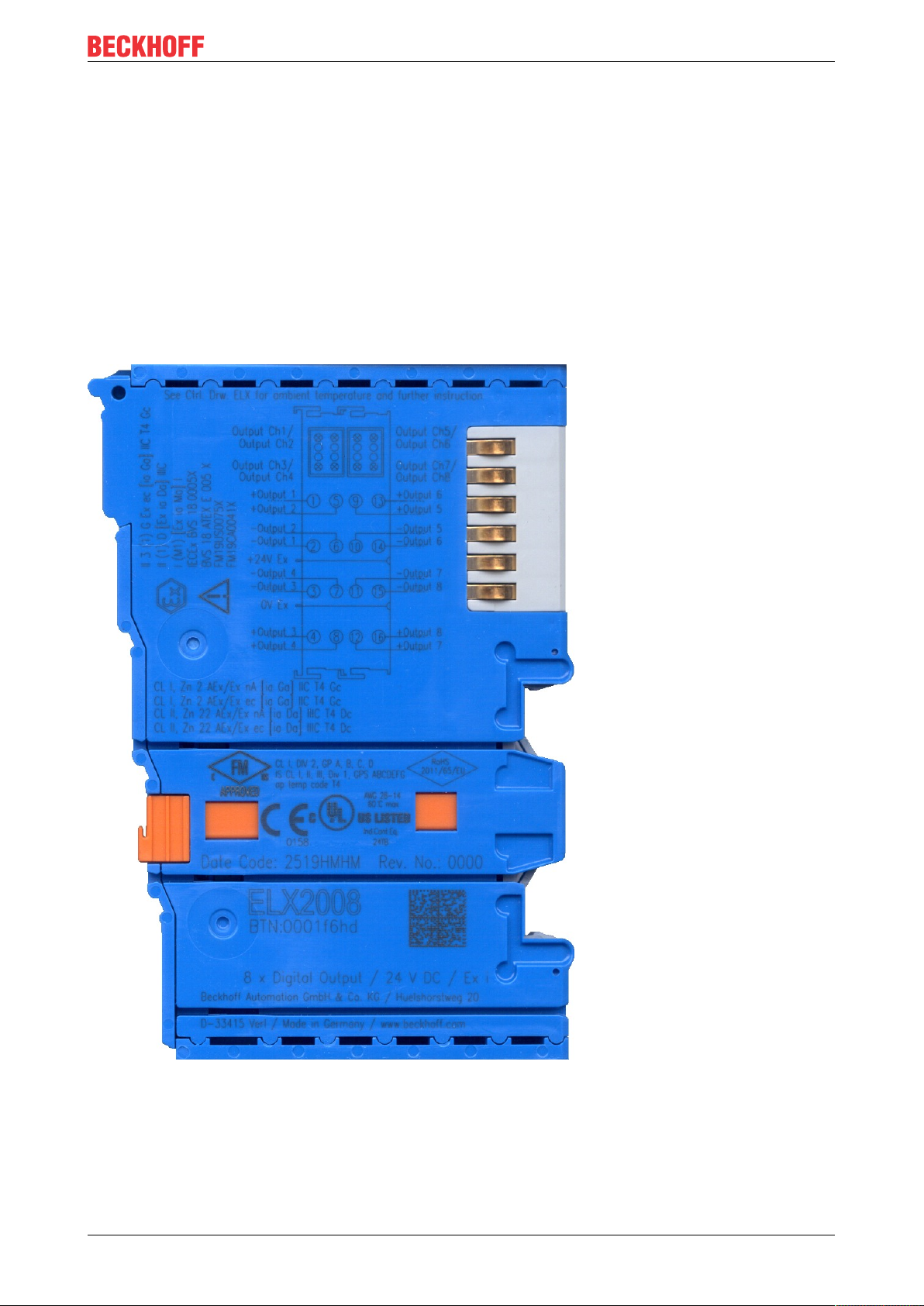
Ex marking
The Ex marking can be found at the top left on the terminal:
II 3 (1) G Ex ec [ia Ga] IIC T4 Gc
II (1) D [Ex ia Da] IIIC
I (M1) [Ex ia Ma] I
IECEx BVS 18.0005X
BVS 18 ATEX E 005 X
Examples
Foreword
Fig.1: ELX2008-0000 with date code 2519HMHM, BTN 0001f6hd and Ex marking
ELX3152 and ELX3158 9Version: 2.1.0
Page 10
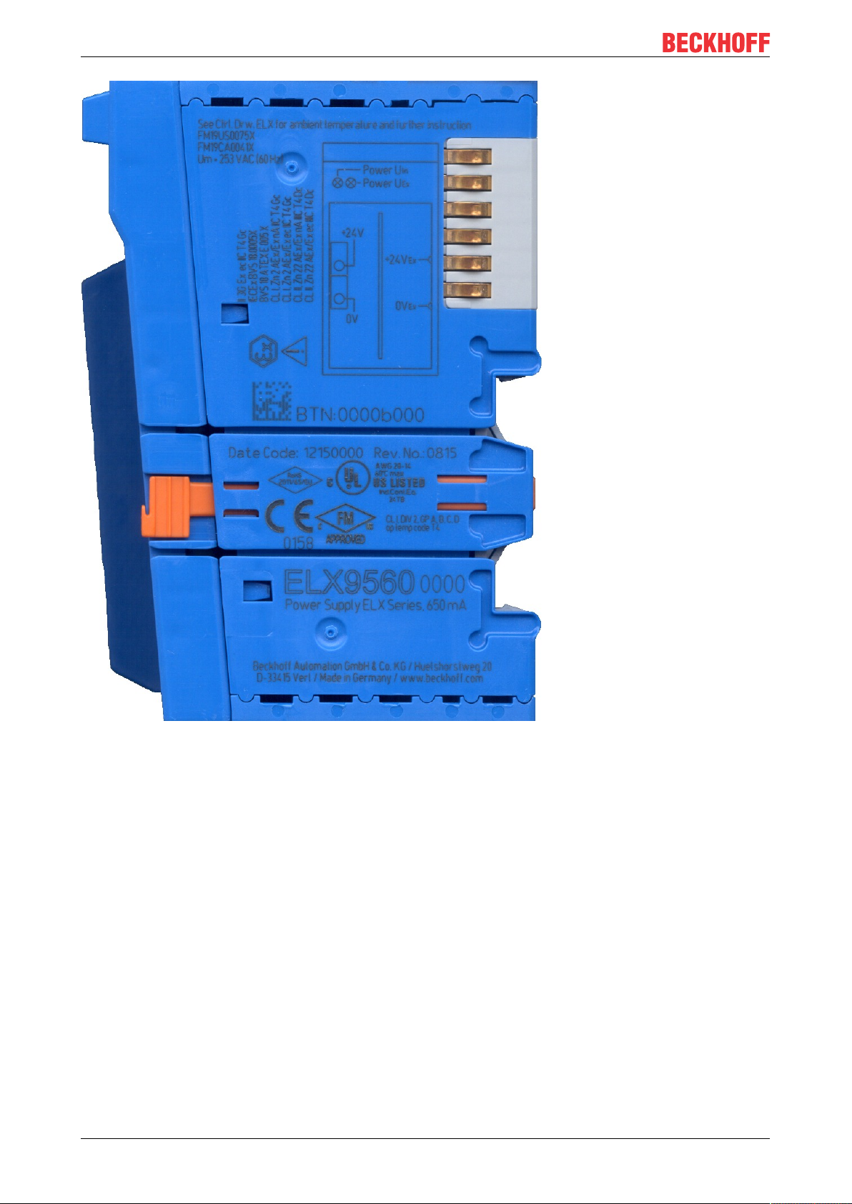
Foreword
Fig.2: ELX9560-0000 with date code 12150000, BTN 000b000 and Ex marking
ELX3152 and ELX315810 Version: 2.1.0
Page 11
Foreword
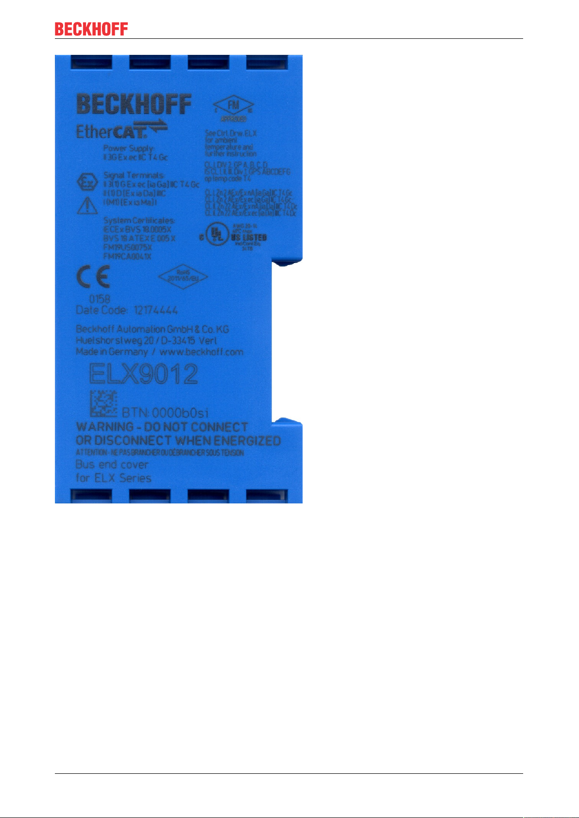
Fig.3: ELX9012 with date code 12174444, BTN 0000b0si and Ex marking
ELX3152 and ELX3158 11Version: 2.1.0
Page 12
Product overview
2 Product overview
2.1 ELX3152 - Introduction
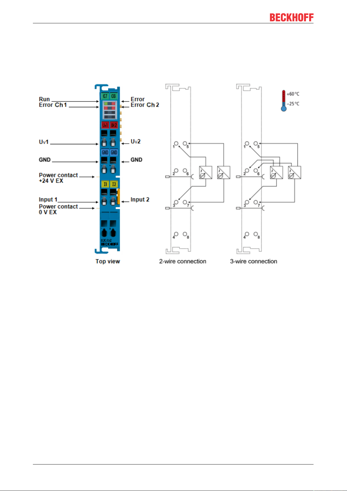
Fig.4: ELX3152 - Two channel, analog input terminal, 0/4 … 20mA, single ended, 16bit, Exi
The ELX3152 analog input terminal is suitable for operation in zone2 and in not explosive areas. It allows
the direct connection of intrinsically safe field devices located in hazardous areas classified Zone 0/20 or
1/21. It supplies measuring transducers located in the field and transmits their analog measuring signals
electrically isolated to the automation device. The EtherCAT terminal indicates the signal state by means of
light emitting diodes. The error LEDs indicate an overload condition and wire breakage.
ELX3152 and ELX315812 Version: 2.1.0
Page 13
2.2 ELX3158 - Introduction
Product overview
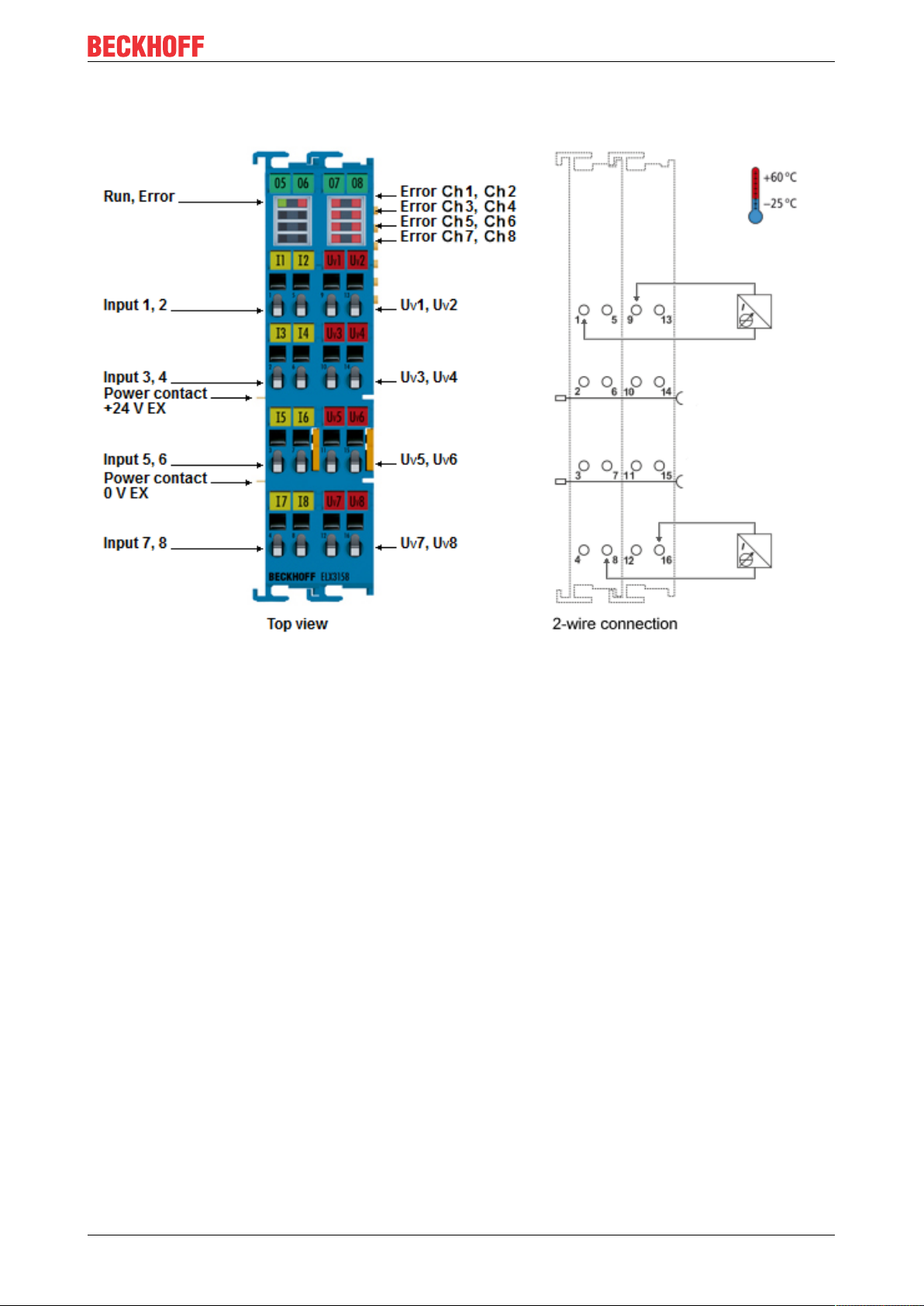
Fig.5: ELX3158 - Eight channel, analog input terminal, 4 … 20mA, single ended, 16bit, Exi
The analog input terminal ELX3158 allows the direct connection of intrinsically safe field devices located in
hazardous areas classified Zone 0/20 or 1/21. It supplies measuring transducers in the field and transmits
their analog measuring signals, electrically isolated, to the automation device. Overload and wire breakage
are indicated by the error LEDs.
ELX3152 and ELX3158 13Version: 2.1.0
Page 14

Product overview
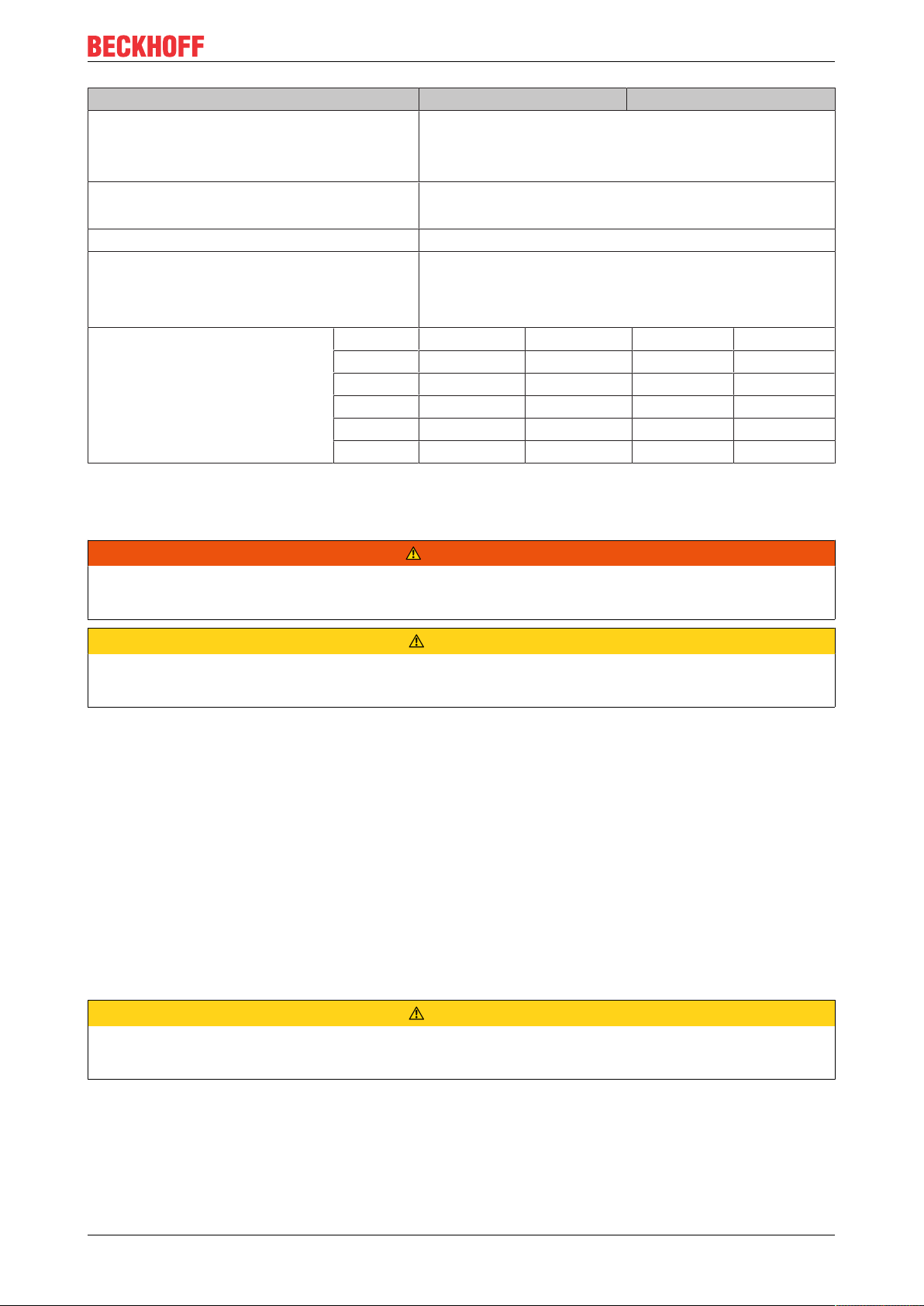
2.3 Technical data
Technical data ELX3152-0000 ELX3158-0000
Technology intrinsically safe sensors
Number of inputs 2 (single ended) 8 (single ended)
Connection technology 2-wire, 3-wire 2-wire
Nominal voltage 24V
Signal current 0/4…20mA 4…20mA
Technical measuring range 107%*
Resolution 16 bit (incl. sign)
Measuring error < ±0.3% (relative to full scale value)
Measuring resistance typically 100Ω
Input filter limit frequency 5kHz
Conversion time typically 1ms
Supply voltage electronics via E-Bus (5VDC) and Power Contacts (24V
Current consumption from the E-Bus typically 85mA typically 75mA
Current consumption from Power Contacts
(ELX9560 power supply)
Electrical isolation 1500V (E-Bus/ field voltage)
Configuration no address or configuration settings required
Distributed Clocks yes
Bit width in the
process image
standard PDO (default) 2 x 4byte 8 x 4byte
compact PDO 2 x 2byte 8 x 2byte
Special features standard and compact process image, activatable FIR/IIR filters,
Weight app. 60g
Permissible ambient temperature range
during operation
Permissible ambient temperature range
during storage
Permissible relative humidity 95%, no condensation
Permissible air pressure
(operation, storage, transport)
Dimensions (W x H x D) app. 15mm x 100mm x 70mm
Mounting on 35mm mounting rail conforms to EN 60715
Vibration/ shock resistance conforms to EN60068-2-6/ EN60068-2-27
EMC immunity/ emission conforms to EN61000-6-2/ EN61000-6-4
Protect. class IP20
Permissible installation position
Markings/ Approvals CE, UL, ATEX, IECEx, cFMus CE, ATEX, IECEx, cFMus
DC
Ex, feeding by
DC
ELX9560)
typically 10 mA + load
limit value monitoring, NE43 NAMUR
-25°C ... + 60°C
-40°C ... + 85°C
800hPa to 1100hPa
(this corresponds to a height of approx. -690m to 2000m over
sea level assuming an international standard atmosphere)
app. 27mm x 100mm x 70mm
(width aligned: 12mm)
(width aligned: 24mm)
See chapter Installation position and minimum distances [}21]
*) With a technical measuring range of 107% of the nominal range, the terminal also supports commissioning
with sensor values in the limit range and an evaluation according to NAMURNE43.
ELX3152 and ELX315814 Version: 2.1.0
Page 15
Product overview
Technical data for explosion protection ELX3152-0000 ELX3158-0000
Ex marking II 3 (1) G Ex ec [ia Ga] IIC T4 Gc
II (1) D [Ex ia Da] IIIC
I (M1) [Ex ia Ma] I
Certificate numbers IECEx BVS 18.0005X
BVS 18 ATEX E 005 X
Power supply Invariable in connection with ELX9560
Field interfaces UO = 27.7V
IO = 85mA
PO = 565mW
Characteristic curve: linear
Reactance (without consideration
of the simultaneousness)
Ex ia I 43mH 3.45µF 43mH 3.45µF
L
0
C
0
L
0
Ex ia IIA 30mH 2.2µF 30mH 2.2µF
Ex ia IIB 18mH 663nF 18mH 663nF
Ex ia IIC 2mH 85nF 2mH 85nF
Ex ia IIIC 18mH 663nF 18mH 663nF
C
0
2.4 Intended use
WARNING
Endangering the safety of persons and equipment!
The ELX components may only be used for the purposes described below!
CAUTION
Observe ATEX and IECEx!
The ELX components may only be used in accordance with the ATEX directive and the IECEx scheme!
The ELX terminals extend the field of application of the Beckhoff bus terminal system with functions for
integrating intrinsically safe field devices from hazardous areas. The intended field of application is data
acquisition and control tasks in discrete and process engineering automation, taking into account explosion
protection requirements.
The ELX terminals are protected by the type of protection "Increased safety" (Exe) according to
IEC60079-7 and must only be operated in hazardous areas of Zone2 or in non-hazardous areas.
The field interfaces of the ELX terminals achieve explosion protection through the type of protection "intrinsic
safety" (Exi) according to IEC60079-11. For this reason, only appropriately certified, intrinsically safe
devices may be connected to the ELX terminals. Observe the maximum permissible connection values for
voltages, currents and reactances. Any infringement can damage the ELX terminals and thus eliminate the
explosion protection.
The ELX terminals are open, electrical equipment for installation in lockable cabinets, enclosures or
operating rooms. Make sure that access to the equipment is only possible for authorized personnel.
CAUTION
Ensure traceability!
The buyer has to ensure the traceability of the device via the Beckhoff Traceability Number (BTN).
ELX3152 and ELX3158 15Version: 2.1.0
Page 16

Mounting and wiring
3 Mounting and wiring
3.1 Special conditions of use for ELX terminals
WARNING
Observe the special conditions of use for the intended use of Beckhoff ELX terminals in
potentially explosive areas (ATEX directive 2014/34/EU)!
• The certified components are to be installed in a suitable housing that guarantees an ingress protection
of at least IP54 in accordance with EN60079-0 and EN60529! The prescribed environmental conditions
during installation, operation and maintenance are thereby to be taken into account! Inside the housing,
pollution degree 1 and 2 are permissible.
• If the temperatures during rated operation are higher than 70°C at the feed-in points of cables, lines or
pipes, or higher than 80°C at the wire branching points, then cables must be selected whose temperature data correspond to the actual measured temperature values!
• Observe the permissible ambient temperature range of -25 to +60°C of Beckhoff ELX terminals!
• Measures must be taken to protect against the rated operating voltage being exceeded by more than
40% due to short-term interference voltages! The power supply of the ELX9560 power supply terminal
must correspond to overvoltage categoryII according to EN60664-1
• The individual terminals may only be unplugged or removed from the bus terminal system if all supply
voltages have been switched off or if a non-explosive atmosphere is ensured!
• The connections of the ELX9560 power supply terminal may only be connected or disconnected if all
supply voltages have been switched off or if a non-explosive atmosphere is ensured!
• The fuses of the EL92xx power feed terminals may only be exchanged if all supply voltages have been
switched off or if a non-explosive atmosphere is ensured!
• Address selectors and switches may only be adjusted if all supply voltages have been switched off or if a
non-explosive atmosphere is ensured!
3.2 Installation notes for ELX terminals
NOTE
Storage, transport and mounting
• Transport and storage are permitted only in the original packaging!
• Store in a dry place, free from vibrations.
• A brand new ELX terminal with a certified build version is delivered only in a sealed carton. Therefore,
check that the carton and all seals are intact before unpacking.
• Do not use the ELX terminal if
- its packaging is damaged
- the terminal is visibly damaged or
- you cannot be sure of the origin of the terminal.
• ELX terminals with a damaged packaging seal are regarded as used.
WARNING
Observe the accident prevention regulations
During mounting, commissioning, operation and maintenance, adhere to the safety regulations, accident
prevention regulations and general technical rules applicable to your devices, machines and plants.
CAUTION
Observe the erection regulations
Observe the applicable erection regulations.
ELX3152 and ELX315816 Version: 2.1.0
Page 17

Mounting and wiring
NOTE
Protect the terminals against electrostatic discharge (ESD)
Electronic components can be destroyed by electrostatic discharge. Therefore, take the safety measures to
protect against electrostatic discharge as described in DIN EN 61340-5-1 among others. In conjunction with
this, ensure that the personnel and surroundings are suitably earthed.
NOTE
Do not place terminals on E-bus contacts
Do not place the ELX terminals on the E-bus contacts located on the right-hand side. The function of the Ebus contacts can be negatively affected by damage caused by this, e.g. scratches.
NOTE
Protect the terminals against dirt
To ensure the functionality of the ELX terminals they must be protected against dirt, especially on the contact points. For this reason use only clean tools and materials.
NOTE
Handling
• It is forbidden to insert conductive or non-conductive objects of any kind into the interior of the housing
(e.g. through the ventilation slots in the housing).
• Use only the openings provided in the housing front and appropriate tools to actuate the spring-loaded
terminal contacts on the front side for attaching connection cables to the terminal; see chapter Wiring
[}24].
• The opening of the housing, the removal of parts and any mechanical deformation or machining of an
ELX terminal are not permitted!
If an ELX terminal is defective or damaged it must be replaced by an equivalent terminal. Do not carry out
any repairs to the devices. For safety reasons repairs may only be carried out by the manufacturer.
NOTE
Contact marking and pin assignment
The colored inscription labels above the front connection contacts shown in the illustrations in the introduction chapter are only examples and are not part of the scope of delivery!
A clear assignment of channel and terminal designation according to the chapter contact assignment to the
actual terminal point can be made via the lasered channel numbers 1 to 8 on the left above the respective
terminal point as well as via the laser image.
Observe any possible polarity dependency of connected intrinsically safe circuits!
ELX3152 and ELX3158 17Version: 2.1.0
Page 18
Mounting and wiring
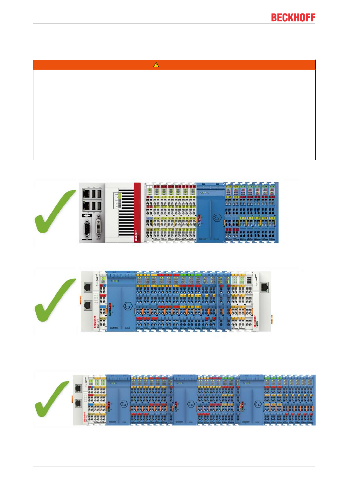
3.3 Arrangement of ELX terminals within a bus terminal block
WARNING
Observe the following instructions for the arrangement of ELX terminals!
• ELX signal terminals must always be installed behind an ELX9560 power supply terminal, without exception!
• Only signal terminals of the ELX series may be installed behind an ELX9560 power supply terminal!
• Multiple ELX9560 power supply terminals may be set in one terminal block as long as one ELX9410 is
placed before each additional ELX9560!
• An ELX9410 power supply terminal must not be mounted to the right of an ELX9560 nor to the left of any
ELX signal terminal!
• The last terminal of each ELX segment is to be covered by an ELX9012 bus end cover, unless two
ELX9410 power supply terminals are installed in direct succession for continuing the same terminal segment with standard Beckhoff EtherCAT terminals (e.g. EL/ES/EK)!
Examples for the arrangement of ELX terminals
Fig.6: Valid arrangement of the ELX terminals (right terminal block).
Fig.7: Valid arrangement - terminals that do not belong to the ELX series are set before and after the ELX
terminal segment. The separation is realized by the ELX9560 at the beginning of the ELX terminal segment
and two ELX9410 at the end of the ELX terminal segment.
Fig.8: Valid arrangement - multiple power supplies by ELX9560, each with an upstream ELX9410.
ELX3152 and ELX315818 Version: 2.1.0
Page 19
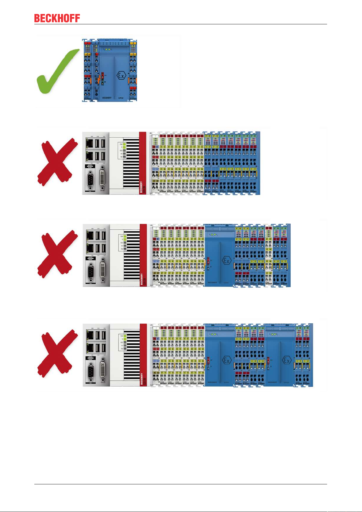
Fig.9: Valid arrangement - ELX9410 in front of an ELX9560 power supply terminal.
Mounting and wiring
Fig.10: Invalid arrangement - missing ELX9560 power supply terminal.
Fig.11: Invalid arrangement - terminal that does not belong to the ELX series within the ELX terminal
segment.
Fig.12: Invalid arrangement - second ELX9560 power supply terminal within the ELX terminal segment
without an upstream ELX9410.
ELX3152 and ELX3158 19Version: 2.1.0
Page 20
Mounting and wiring
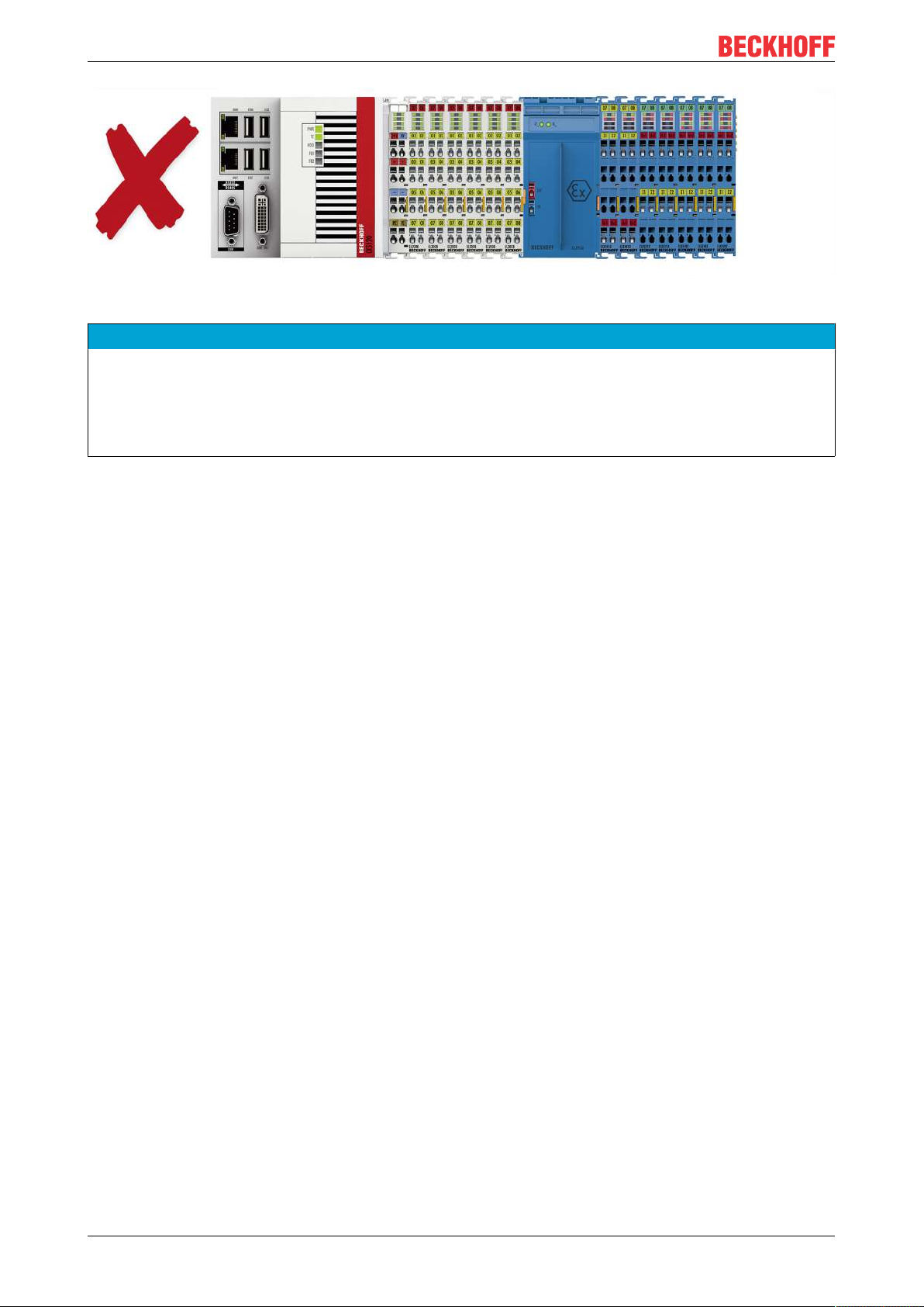
Fig.13: Invalid arrangement - missing ELX9012 bus end cover.
NOTE
Observe the maximum output current of the ELX9560
When configuring the ELX terminal segment, please note the maximum available output current of the
ELX9560 power supply terminal in accordance with the specified technical data.
If required, an additional power supply terminal ELX9560 with an upstream ELX9410 connected (see
mounting examples) must be installed or a completely new terminal block must be assembled.
ELX3152 and ELX315820 Version: 2.1.0
Page 21
Mounting and wiring
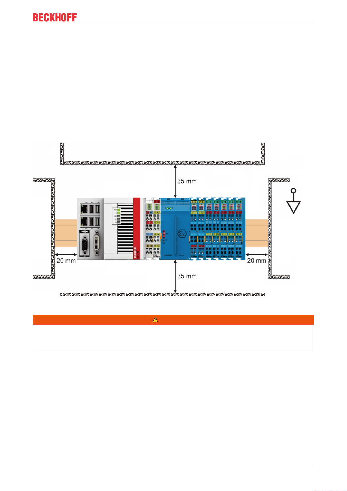
3.4 Installation position and minimum distances
Installation position
For the prescribed installation position the mounting rail is installed horizontally and the mating surfaces of
the ELX terminals point toward the front (see illustration below). The terminals are ventilated from below,
which enables optimum cooling of the electronics through convection. The direction indication “down”
corresponds to the direction of positive acceleration due to gravity.
Minimum distances
Observe the following minimum distances to ensure optimum convection cooling:
• above and below the ELX terminals: 35mm (required!)
• besides the bus terminal block: 20mm (recommended)
Fig.14: Installation position and minimum distances
WARNING
Observe the minimum separation distances according to IEC 60079-14!
Observe the prescribed minimum separation distances between intrinsically safe and non-intrinsically safe
circuits according to IEC 60079-14.
ELX3152 and ELX3158 21Version: 2.1.0
Page 22
Mounting and wiring
3.5 Installation of ELX terminals on mounting rails
WARNING
Risk of electric shock and damage of device!
Bring the bus terminal system into a safe, powered down state before starting installation, disassembly or
wiring of the bus terminals!
CAUTION
Danger of injury due to power contacts!
For your own protection, pay attention to careful and careful handling of the ELX terminals. In particular, the
left side mounted, sharp-edged blade contacts pose a potential risk of injury.
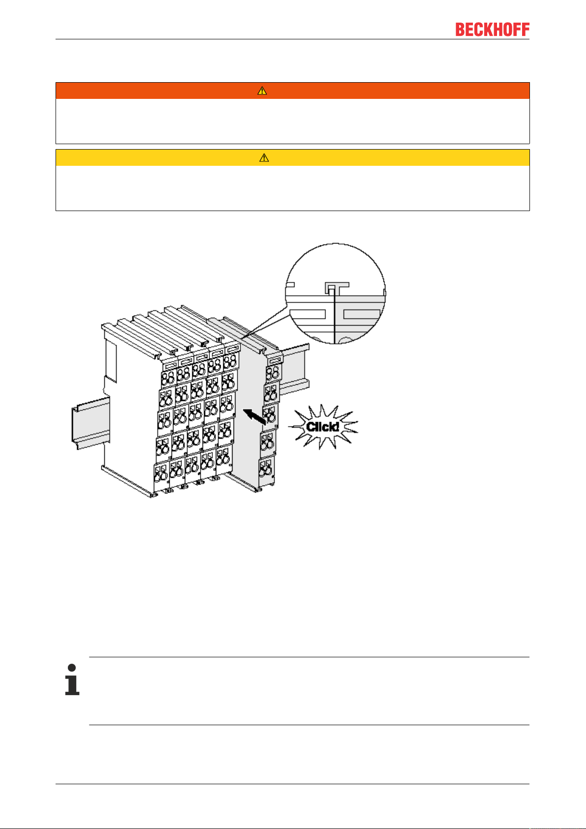
Assembly
Fig.15: Attaching on mounting rail
The bus coupler and bus terminals are attached to commercially available 35mm mounting rails (DIN rails
according to EN60715) by applying slight pressure:
1. First attach the fieldbus coupler to the mounting rail.
2. The bus terminals are now attached on the right-hand side of the fieldbus coupler. Join the components with tongue and groove and push the terminals against the mounting rail, until the lock clicks
onto the mounting rail.
If the terminals are clipped onto the mounting rail first and then pushed together without tongue and
groove, the connection will not be operational! When correctly assembled, no significant gap should
be visible between the housings.
Fixing of mounting rails
The locking mechanism of the terminals and couplers extends to the profile of the mounting rail. At
the installation, the locking mechanism of the components must not come into conflict with the fixing
bolts of the mounting rail. To mount the mounting rails with a height of 7.5mm under the terminals
and couplers, you should use flat mounting connections (e.g. countersunk screws or blind rivets).
ELX3152 and ELX315822 Version: 2.1.0
Page 23
Mounting and wiring
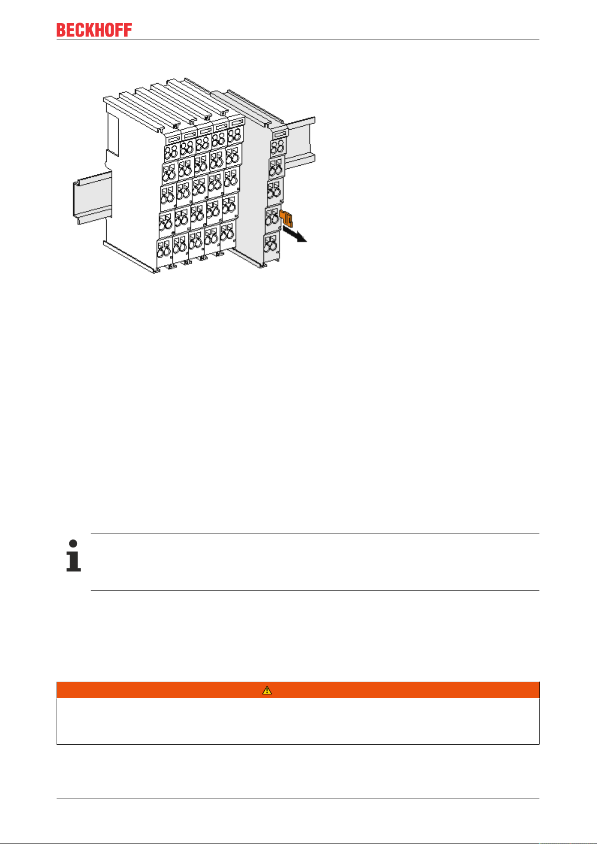
Disassembly
Fig.16: Disassembling of terminal
Each terminal is secured by a lock on the mounting rail, which must be released for disassembly:
1. Pull the terminal by its orange-colored lugs approximately 1cm away from the mounting rail. In doing
so for this terminal the mounting rail lock is released automatically and you can pull the terminal out of
the bus terminal block easily without excessive force.
2. Grasp the released terminal with thumb and index finger simultaneous at the upper and lower grooved
housing surfaces and pull the terminal out of the bus terminal block.
Connections within a bus terminal block
The electric connections between the Bus Coupler and the Bus Terminals are automatically realized by
joining the components:
• The six spring contacts of the E-Bus deal with the transfer of the data and the supply of the Bus
Terminal electronics.
• The power contacts deal with the supply for the field electronics and thus represent a supply rail within
the bus terminal block.
The power contacts of the ELX terminals are supplied by the ELX9560 power terminal. This interrupts
the power contacts and thus represents the beginning of a new supply rail.
Power Contacts
During the design of a bus terminal block, the pin assignment of the individual Bus Terminals must
be taken account of, since some types (e.g. analog Bus Terminals or digital 4-channel Bus Terminals) do not or not fully loop through the power contacts.
3.6 Connection
3.6.1 Connection system
WARNING
Risk of electric shock and damage of device!
Bring the bus terminal system into a safe, powered down state before starting installation, disassembly or
wiring of the bus terminals!
The terminals of ELXxxxx series include electronics and connection level in a single enclosure.
ELX3152 and ELX3158 23Version: 2.1.0
Page 24
Mounting and wiring
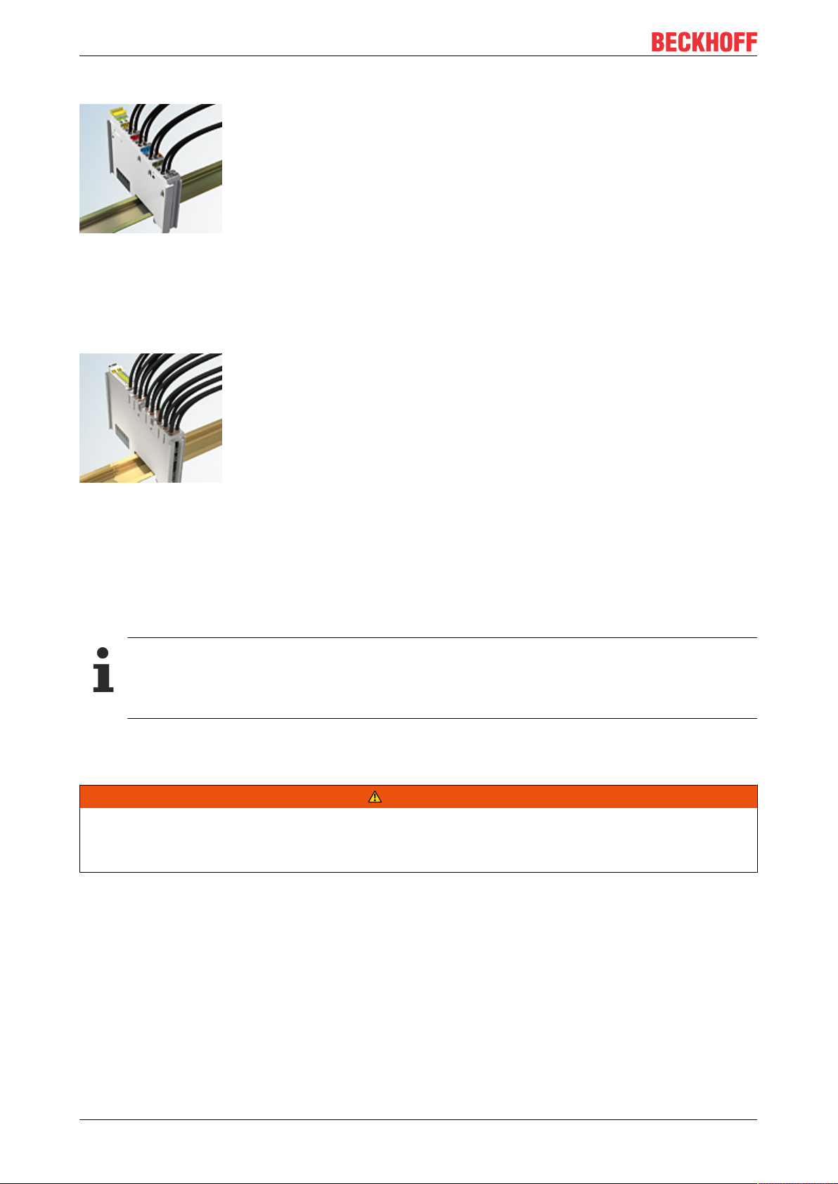
Standard wiring
Fig.17: Standard wiring
The terminals of ELXxxxx series feature integrated screwless spring force technology for fast and simple
assembly.
High Density Terminals (HD Terminals)
Fig.18: High Density Terminals
The Bus Terminals from these series with 16 connection points are distinguished by a particularly compact
design, as the packaging density is twice as large as that of the standard 12mm Bus Terminals. Massive
conductors and conductors with a wire end sleeve can be inserted directly into the spring loaded terminal
point without tools.
Ultrasonically "bonded" (ultrasonically welded) conductors
Ultrasonically “bonded" conductors
It is also possible to connect the Standard and High Density Terminals with ultrasonically
"bonded" (ultrasonically welded) conductors. In this case, please note the tables concerning the
wire-size width below!
3.6.2 Wiring
WARNING
Risk of electric shock and damage of device!
Bring the bus terminal system into a safe, powered down state before starting installation, disassembly or
wiring of the bus terminals!
ELX3152 and ELX315824 Version: 2.1.0
Page 25
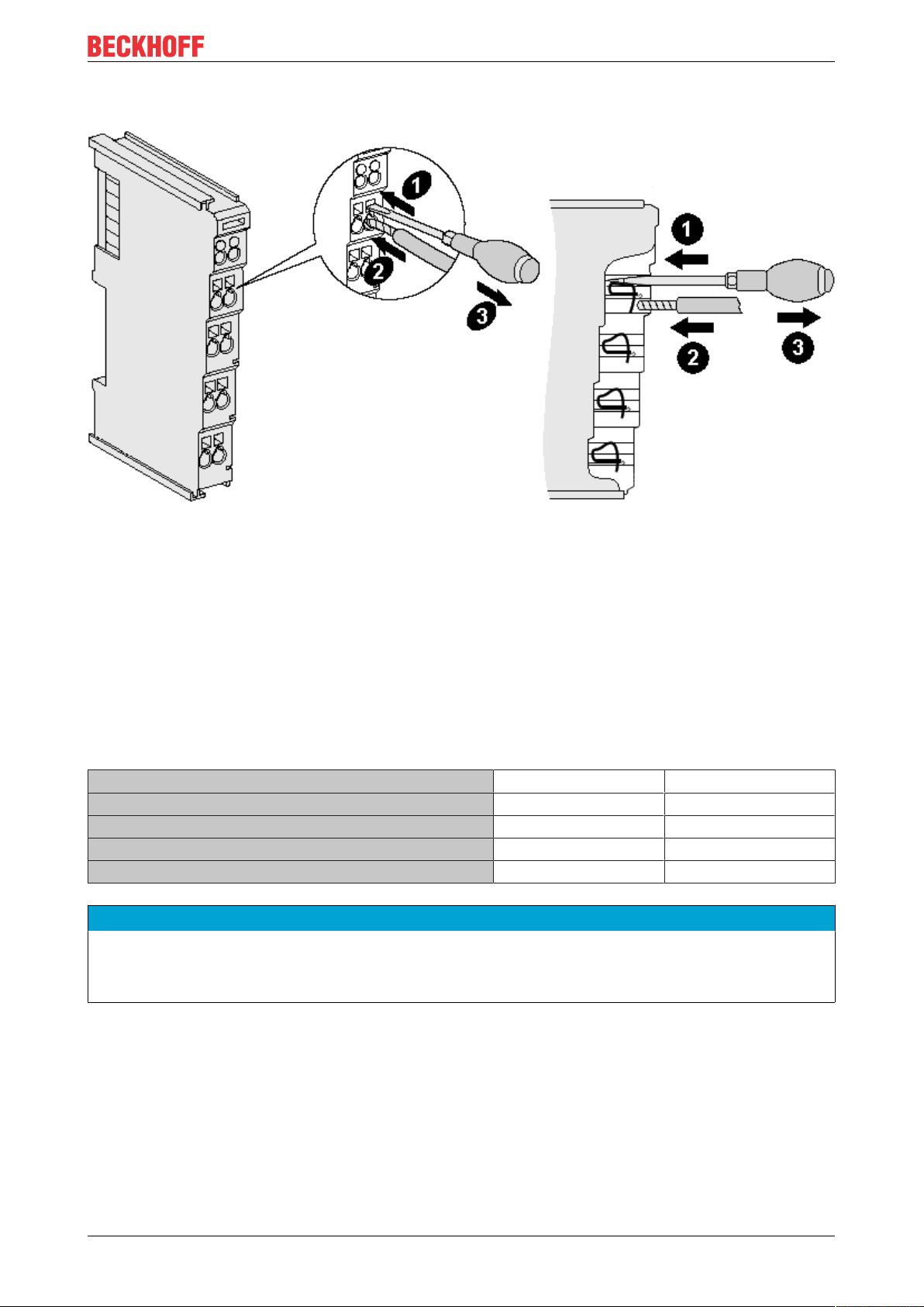
Terminals for standard wiring
Mounting and wiring
Fig.19: Connecting a cable on a terminal point
Up to eight terminal points enable the connection of solid or finely stranded cables to the Bus Terminal. The
terminal points are implemented in spring force technology. Connect the cables as follows:
1. Open a terminal point by pushing a screwdriver straight against the stop into the square opening
above the terminal point. Do not turn the screwdriver or move it alternately (don't toggle).
2. The wire can now be inserted into the round terminal opening without any force.
3. The terminal point closes automatically when the pressure is released, holding the wire securely and
permanently.
Observe the requirements for connecting cables and cross sections according to IEC 60079-7 and IEC
60079-11. See the following tables for the suitable wire size width.
Terminal housing Standard wiring ELX9560
Wire size width (single core wires) 0.08 ... 2.5mm
Wire size width (fine-wire conductors) 0.08 ... 2.5mm
Wire size width (conductors with a wire end sleeve) 0.14 ... 1.5mm
2
2
2
0.14 ... 1.5mm
0.14 ... 1.5mm
0.14 ... 1.0mm
2
2
2
Wire stripping length 8 ... 9mm 8 ... 9mm
NOTE
Maximum screwdriver width for ELX9560
Use a screwdriver with a maximum width of 2mm to wire the ELX9560 power supply terminal. Wider
screwdrivers can damage the terminal points.
High Density Terminals (HD Terminals) with 16 terminal points
The conductors of the HD Terminals are connected without tools for single-wire conductors using the direct
plug-in technique, i.e. after stripping the wire is simply plugged into the terminal point. The cables are
released, as usual, using the contact release with the aid of a screwdriver. See the following table for the
suitable wire size width.
ELX3152 and ELX3158 25Version: 2.1.0
Page 26
Mounting and wiring
Terminal housing High Density Housing
Wire size width (single core wires) 0.08 ... 1.5mm
Wire size width (fine-wire conductors) 0.25 ... 1.5mm
Wire size width (conductors with a wire end sleeve) 0.14 ... 0.75mm
Wire size width (ultrasonically “bonded" conductors) only 1.5mm
2
2
2
2
Wire stripping length 8 ... 9mm
3.6.3 Proper line connection
Always connect only one wire per terminal point.
When using fine-wire conductors it is recommended to connect them with wire end sleeves in order to
establish a safe, conductive connection.
In addition, make sure that the pin assignment is correct to prevent damage to the ELX terminals and the
connected devices.
3.6.4 Shielding and potential separation
Shielding
Encoder, analog sensors and actors should always be connected with shielded, twisted paired
wires.
CAUTION
Observe installation requirements in areas of potentially explosive atmospheres!
During installation, observe the requirements for cables, shielding and earth potential equalization in areas
of potentially explosive atmospheres according to IEC60079-11, IEC60079-14 and IEC60079-25.
WARNING
Ensure potential separation of the 24V Ex busbar!
In any case, make sure that the galvanic isolation made by the ELX9560 between the 24V Ex busbar
(power contacts +24VEx and 0VEx) and other system potentials (if applicable also functional or protective earths) is not removed.
ELX3152 and ELX315826 Version: 2.1.0
Page 27
3.6.5 ELX3152 - Contact assignment
Mounting and wiring
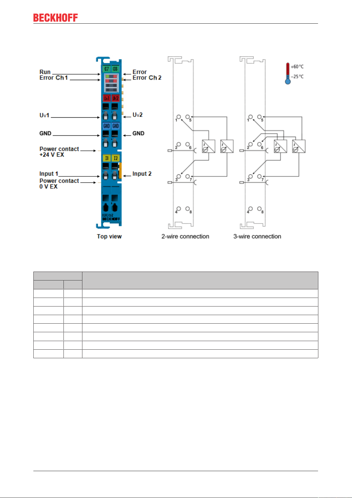
Fig.20: ELX3152 - Contact assignment
Terminal point Description
Name No.
Uv1 1 Supply voltage for channel 1
GND 2 Ground for channel 1 (for using a 3-wire connection)
Input 1 3 Signal input channel 1
4 not implemented
Uv2 5 Supply voltage for channel 2
GND 6 Ground for channel 2 (for using a 3-wire connection)
Input 2 7 Signal input channel 2
8 not implemented
ELX3152 and ELX3158 27Version: 2.1.0
Page 28

Mounting and wiring
LED display
LED Color Meaning
Run green This LED indicates the terminal's operating state:
off State of the EtherCAT State Machine: INIT = initialization of the terminal or
BOOTSTRAP = function for firmware updates of the terminal
flashing State of the EtherCAT State Machine: PREOP = function for mailbox
communication and different standard-settings set
single
flash
on State of the EtherCAT State Machine: OP = normal operating state; mailbox and
Error red General error of the A/D converter
Error Ch 1 red Fault indication in the event of broken wire or undershooting or overshooting of the
measuring range for channel1
Error Ch 2 red Fault indication in the event of broken wire or undershooting or overshooting of the
measuring range for channel2
State of the EtherCAT State Machine: SAFEOP = verification of the Sync
Manager [}91] channels and the distributed clocks.
Outputs remain in safe state
process data communication is possible
ELX3152 and ELX315828 Version: 2.1.0
Page 29
3.6.6 ELX3158 - Contact assignment
Mounting and wiring
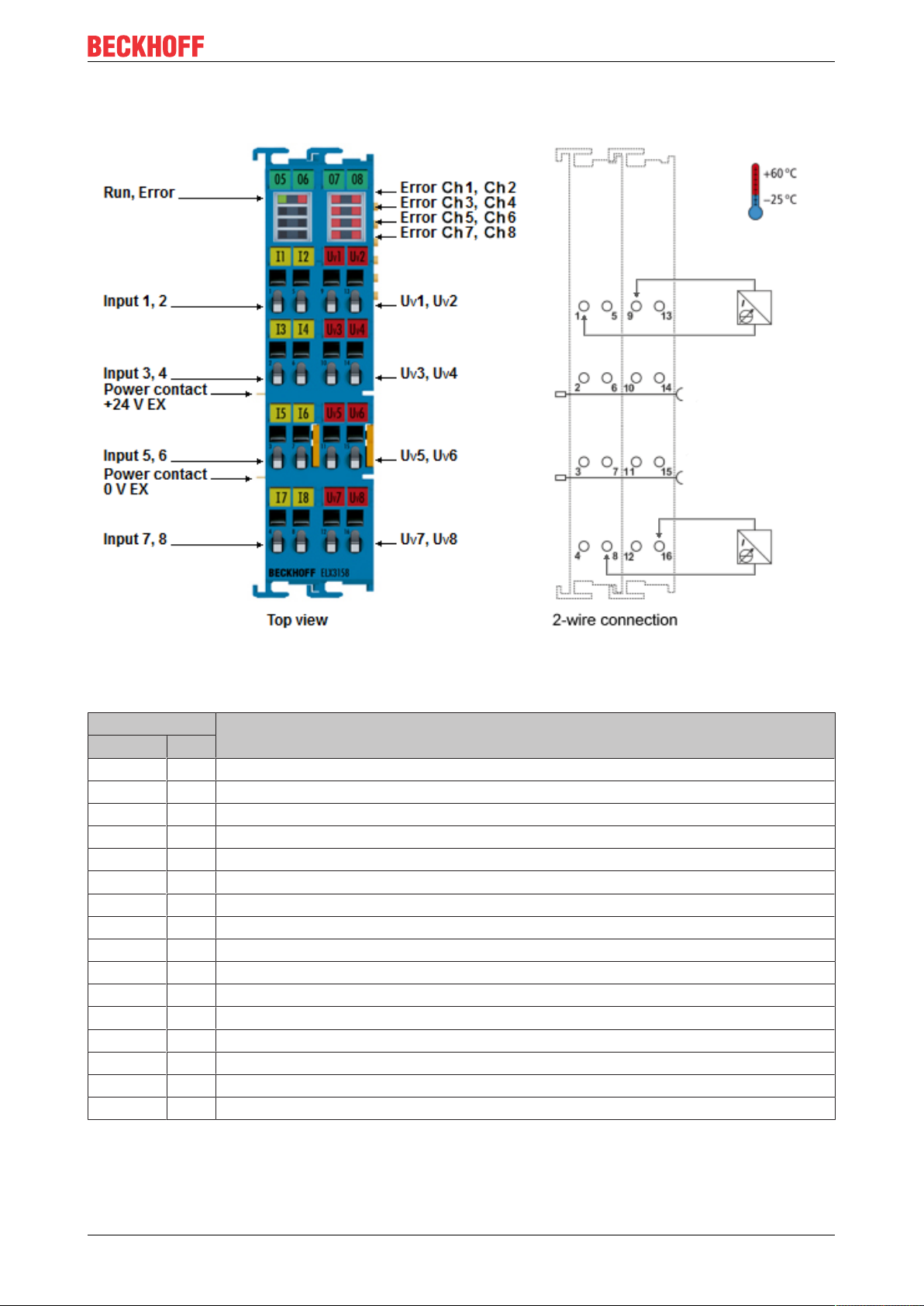
Fig.21: ELX3158 - Contact assignment
Terminal point Description
Name No.
Input 1 1 Signal input channel 1
Input 3 2 Signal input channel 3
Input 5 3 Signal input channel 5
Input 7 4 Signal input channel 7
Input 2 5 Signal input channel 2
Input 4 6 Signal input channel 4
Input 6 7 Signal input channel 6
Input 8 8 Signal input channel 8
Uv1 9 Supply voltage for channel 1
Uv3 10 Supply voltage for channel 3
Uv5 11 Supply voltage for channel 5
Uv7 12 Supply voltage for channel 7
Uv2 13 Supply voltage for channel 2
Uv4 14 Supply voltage for channel 4
Uv6 15 Supply voltage for channel 6
Uv8 16 Supply voltage for channel 8
ELX3152 and ELX3158 29Version: 2.1.0
Page 30

Mounting and wiring
LED display
LED Color Meaning
Run green This LED indicates the terminal's operating state:
off State of the EtherCAT State Machine: INIT = initialization of the terminal or
BOOTSTRAP = function for firmware updates of the terminal
flashing State of the EtherCAT State Machine: PREOP = function for mailbox
communication and different standard-settings set
single
flash
on State of the EtherCAT State Machine: OP = normal operating state; mailbox and
Error red General error of the A/D converter
Error Ch 1 red Fault indication in the event of broken wire or undershooting or overshooting of the
measuring range for channel1
Error Ch 2 red Fault indication in the event of broken wire or undershooting or overshooting of the
measuring range for channel2
Error Ch 3 red Fault indication in the event of broken wire or undershooting or overshooting of the
measuring range for channel3
Error Ch 4 red Fault indication in the event of broken wire or undershooting or overshooting of the
measuring range for channel4
Error Ch 5 red Fault indication in the event of broken wire or undershooting or overshooting of the
measuring range for channel5
Error Ch 6 red Fault indication in the event of broken wire or undershooting or overshooting of the
measuring range for channel6
Error Ch 7 red Fault indication in the event of broken wire or undershooting or overshooting of the
measuring range for channel7
Error Ch 8 red Fault indication in the event of broken wire or undershooting or overshooting of the
measuring range for channel8
State of the EtherCAT State Machine: SAFEOP = verification of the Sync
Manager [}91] channels and the distributed clocks.
Outputs remain in safe state
process data communication is possible
ELX3152 and ELX315830 Version: 2.1.0
Page 31

Basic function principles
4 Basic function principles
4.1 EtherCAT basics
Please refer to the EtherCAT System Documentation for the EtherCAT fieldbus basics, also available as PDF
file from www.beckhoff.com.
4.2 Notices on analog specifications
Beckhoff I/O devices (terminals, boxes, modules) with analog inputs are characterized by a number of
technical characteristic data; refer to the technical data in the respective documents.
Some explanations are given below for the correct interpretation of these characteristic data.
4.2.1 Full scale value (FSV)
An I/O device with an analog input measures over a nominal measuring range that is limited by an upper and
a lower limit (initial value and end value); these can usually be taken from the device designation.
The range between the two limits is called the measuring span and corresponds to the equation (end value initial value). Analogous to pointing devices this is the measuring scale (see IEC61131) or also the dynamic
range.
For analog I/O devices from Beckhoff the rule is that the limit with the largest value is chosen as the full scale
value of the respective product (also called the reference value) and is given a positive sign. This applies to
both symmetrical and asymmetrical measuring spans.
Fig.22: Full scale value, measuring span
For the above examples this means:
• Measuring range 0...10V: asymmetric unipolar, full scale value=10V, measuring span=10V
• Measuring range 4...20 mA: asymmetric unipolar, full scale value = 20mA, measuring span=16mA
• Measuring range -200...1370°C: asymmetric bipolar, full scale value=1370°C, measuring
span=1570°C
• Measuring range -10...+10V: symmetric bipolar, full scale value = 10V, measuring span=20V
This applies to analog output terminals/ boxes (and related Beckhoff product groups).
4.2.2 Measuring error/ measurement deviation
The relative measuring error (% of the full scale value) is referenced to the full scale value and is calculated
as the quotient of the largest numerical deviation from the true value (‘measuring error’) referenced to the full
scale value.
ELX3152 and ELX3158 31Version: 2.1.0
Page 32

Basic function principles
The measuring error is generally valid for the entire permitted operating temperature range, also called the
‘usage error limit’ and contains random and systematic portions of the referred device (i.e. ‘all’ influences
such as temperature, inherent noise, aging, etc.).
It is always to be regarded as a positive/negative span with ±, even if it is specified without ± in some cases.
The maximum deviation can also be specified directly.
Example: Measuring range 0...10V and measuring error <±0.3% full scale value → maximum deviation ±
30mV in the permissible operating temperature range.
Lower measuring error
Since this specification also includes the temperature drift, a significantly lower measuring error can
usually be assumed in case of a constant ambient temperature of the device and thermal stabilization after a user calibration.
This applies to analog output devices.
4.2.3 Temperature coefficient tK [ppm/K]
An electronic circuit is usually temperature dependent to a greater or lesser degree. In analog measurement
technology this means that when a measured value is determined by means of an electronic circuit, its
deviation from the “true” value is reproducibly dependent on the ambient/operating temperature.
A manufacturer can alleviate this by using components of a higher quality or by software means.
The temperature coefficient, when indicated, specified by Beckhoff allows the user to calculate the expected
measuring error outside the basic accuracy at 23 °C.
Due to the extensive uncertainty considerations that are incorporated in the determination of the basic
accuracy (at 23 °C), Beckhoff recommends a quadratic summation.
Example: Let the basic accuracy at 23 °C be ±0.01% typ. (full scale value), tK = 20 ppm/K typ.; the accuracy
A35 at 35 °C is wanted, hence ΔT = 12 K
Remarks: ppm ≙ 10
-6
% ≙ 10
-2
ELX3152 and ELX315832 Version: 2.1.0
Page 33

Basic function principles
4.2.4 Single-ended/differential typification
For analog inputs Beckhoff makes a basic distinction between two types: single-ended (SE) and differential
(DIFF), referring to the difference in electrical connection with regard to the potential difference.
The diagram shows two-channel versions of an SE module and a DIFF module as examples for all multichannel versions.
Fig.23: SE and DIFF module as 2-channel version
Note: Dashed lines indicate that the respective connection may not necessarily be present in each SE or
DIFF module. Electrical isolated channels are operating as differential type in general, hence there is no
direct relation (voltaic) to ground within the module established at all. Indeed, specified information to
recommended and maximum voltage levels have to be taken into account.
The basic rule:
• Analog measurements always take the form of voltage measurements between two potential points.
For voltage measurements a large R is used, in order to ensure a high impedance. For current
measurements a small R is used as shunt. If the purpose is resistance measurement, corresponding
considerations are applied.
◦ Beckhoff generally refers to these two points as input+/signal potential and input-/reference
potential.
◦ For measurements between two potential points two potentials have to be supplied.
◦ Regarding the terms “single-wire connection” or “three-wire connection”, please note the following
for pure analog measurements: three- or four-wire connections can be used for sensor supply, but
are not involved in the actual analog measurement, which always takes place between two
potentials/wires.
In particular this also applies to SE, even though the term suggest that only one wire is required.
• The term “electrical isolation” should be clarified in advance.
Beckhoff IO modules feature 1..8 or more analog channels; with regard to the channel connection a
distinction is made in terms of:
◦ how the channels WITHIN a module relate to each other, or
◦ how the channels of SEVERAL modules relate to each other.
ELX3152 and ELX3158 33Version: 2.1.0
Page 34

Basic function principles
The property of electrical isolation indicates whether the channels are directly connected to each
other.
◦ Beckhoff terminals/ boxes (and related product groups) always feature electrical isolation between
the field/analog side and the bus/EtherCAT side. In other words, if two analog terminals/ boxes are
not connected via the power contacts (cable), the modules are effectively electrically isolated.
◦ If channels within a module are electrically isolated, or if a single-channel module has no power
contacts, the channels are effectively always differential. See also explanatory notes below.
Differential channels are not necessarily electrically isolated.
• Analog measuring channels are subject to technical limits, both in terms of the recommended operating
range (continuous operation) and the destruction limit. Please refer to the respective terminal/ box
documentation for further details.
Explanation
• differential (DIFF)
◦ Differential measurement is the most flexible concept. The user can freely choose both connection
points, input+/signal potential and input-/reference potential, within the framework of the technical
specification.
◦ A differential channel can also be operated as SE, if the reference potential of several sensors is
linked. This interconnection may take place via the system GND.
◦ Since a differential channel is configured symmetrically internally (cf. Fig. SE and DIFF module as
2-channel variant), there will be a mid-potential (X) between the two supplied potentials that is the
same as the internal ground/reference ground for this channel. If several DIFF channels are used
in a module without electrical isolation, the technical property VCM (common-mode voltage)
indicates the degree to which the mean voltage of the channels may differ.
◦ The internal reference ground may be accessible as connection point at the terminal/ box, in order
to stabilize a defined GND potential in the terminal/ box. In this case it is particularly important to
pay attention to the quality of this potential (noiselessness, voltage stability). At this GND point a
wire may be connected to make sure that V
If differential channels are not electrically isolated, usually only one V
is not exceeded in the differential sensor cable.
CM,max
is permitted. If the
CM, max
channels are electrically isolated this limit should not apply, and the channels voltages may differ
up to the specified separation limit.
◦ Differential measurement in combination with correct sensor wiring has the special advantage that
any interference affecting the sensor cable (ideally the feed and return line are arranged side by
side, so that interference signals have the same effect on both wires) has very little effect on the
measurement, since the potential of both lines varies jointly (hence the term common mode). In
simple terms: Common-mode interference has the same effect on both wires in terms of amplitude
and phasing.
◦ Nevertheless, the suppression of common-mode interference within a channel or between
channels is subject to technical limits, which are specified in the technical data.
◦ Further helpfully information on this topic can be found on the documentation page Configuration
of 0/4..20mA differential inputs (see documentation for the EL30xx terminals, for example).
• Single Ended (SE)
◦ If the analog circuit is designed as SE, the input/reference wire is internally fixed to a certain
potential that cannot be changed. This potential must be accessible from outside on at least one
point for connecting the reference potential, e.g. via the power contacts (cable).
◦ In other words, in situations with several channels SE offers users the option to avoid returning at
least one of the two sensor cables to the terminal/ box (in contrast to DIFF). Instead, the reference
wire can be consolidated at the sensors, e.g. in the system GND.
◦ A disadvantage of this approach is that the separate feed and return line can result in voltage/
current variations, which a SE channel may no longer be able to handle. See common-mode
interference. A VCM effect cannot occur, since the module channels are internally always 'hardwired' through the input/reference potential.
ELX3152 and ELX315834 Version: 2.1.0
Page 35

Basic function principles
Typification of the 2/3/4-wire connection of current sensors
Current transducers/sensors/field devices (referred to in the following simply as ‘sensor’) with the industrial
0/4-20 mA interface typically have internal transformation electronics for the physical measured variable
(temperature, current, etc.) at the current control output. These internal electronics must be supplied with
energy (voltage, current). The type of cable for this supply thus separates the sensors into self-supplied or
externally supplied sensors:
Self-supplied sensors
• The sensor draws the energy for its own operation via the sensor/signal cable + and -.
So that enough energy is always available for the sensor’s own operation and open-circuit detection is
possible, a lower limit of 4mA has been specified for the 4-20mA interface; i.e. the sensor allows a
minimum current of 4mA and a maximum current of 20mA to pass.
• 2-wire connection see Fig. 2-wire connection, cf. IEC60381-1
• Such current transducers generally represent a current sink and thus like to sit between + and – as a
‘variable load’. Refer also to the sensor manufacturer’s information.
Fig.24: 2-wire connection
Therefore, they are to be connected according to the Beckhoff terminology as follows:
preferably to ‘single-ended’ inputs if the +Supply connections of the terminal/ box are also to be used connect to +Supply and Signal
they can, however, also be connected to ‘differential’ inputs, if the termination to GND is then
manufactured on the application side – to be connected with the right polarity to +Signal and –Signal
It is important to refer to the information page Configuration of 0/4..20mA differential inputs (see
documentation for the EL30xx terminals, for example)!
Externally supplied sensors
WARNING
An external supply of sensors / actuators, which are connected to signal terminals of the
ELX series is not permitted!
In terms of intrinsic safety, all signal terminals of the ELX series are energy-supplying, associated equipment. For this reason, connected sensors or actuators are supplied exclusively via the respective channel
of the terminal and must not be externally supplied in any form (e.g. via an additional, external supply voltage).
This limitation is also independent of whether the additional, external supply is energy limited in the sense
of IEC60079-11.
Connecting any externally powered, intrinsically safe circuits to a ELX signal terminal contradicts the intended use and the specified technical data for explosion protection. The explosion protection provided by
the specified type of protection thus automatically expires.
ELX3152 and ELX3158 35Version: 2.1.0
Page 36

Basic function principles
4.2.5 Common-mode voltage and reference ground (based on differential inputs)
Common-mode voltage (Vcm) is defined as the average value of the voltages of the individual connections/
inputs and is measured/specified against reference ground.
Fig.25: Common-mode voltage (Vcm)
The definition of the reference ground is important for the definition of the permitted common-mode voltage
range and for measurement of the common-mode rejection ratio (CMRR) for differential inputs.
The reference ground is also the potential against which the input resistance and the input impedance for
single-ended inputs or the common-mode resistance and the common-mode impedance for differential
inputs is measured.
The reference ground is usually accessible at or near the terminal/ box, e.g. at the terminal contacts, power
contacts (cable) or a mounting rail. Please refer to the documentation regarding positioning. The reference
ground should be specified for the device under consideration.
For multi-channel terminals/ boxes with resistive (=direct, ohmic, galvanic) or capacitive connection between
the channels, the reference ground should preferably be the symmetry point of all channels, taking into
account the connection resistances.
Reference ground samples for Beckhoff IO devices:
1. Internal AGND fed out: EL3102/EL3112, resistive connection between the channels
2. 0V power contact: EL3104/EL3114, resistive connection between the channels and AGND; AGND
connected to 0V power contact with low-resistance
3. Earth or SGND (shield GND):
◦ EL3174-0002: Channels have no resistive connection between each other, although they are
capacitively coupled to SGND via leakage capacitors
◦ EL3314: No internal ground fed out to the terminal points, although capacitive coupling to SGND
4.2.6 Dielectric strength
A distinction should be made between:
• Dielectric strength (destruction limit): Exceedance can result in irreversible changes to the electronics
◦ Against a specified reference ground
◦ Differential
• Recommended operating voltage range: If the range is exceeded, it can no longer be assumed that the
system operates as specified
◦ Against a specified reference ground
◦ Differential
ELX3152 and ELX315836 Version: 2.1.0
Page 37

Basic function principles
Fig.26: Recommended operating voltage range
The device documentation may contain particular specifications and timings, taking into account:
• Self-heating
• Rated voltage
• Insulating strength
• Edge steepness of the applied voltage or holding periods
• Normative environment (e.g. PELV)
4.2.7 Temporal aspects of analog/digital conversion
The conversion of the constant electrical input signal to a value-discrete digital and machine-readable form
takes place in the analog Beckhoff EL/KL/EP input modules with ADC (analog digital converter). Although
different ADC technologies are in use, from a user perspective they all have a common characteristic: after
the conversion a certain digital value is available in the controller for further processing. This digital value,
the so-called analog process data, has a fixed temporal relationship with the “original parameter”, i.e. the
electrical input value. Therefore, corresponding temporal characteristic data can be determined and specified
for Beckhoff analogue input devices.
This process involves several functional components, which act more or less strongly in every AI (analog
input) module:
• the electrical input circuit
• the analog/digital conversion
• the digital further processing
• the final provision of the process and diagnostic data for collection at the fieldbus (EtherCAT, K‑bus,
etc.)
Fig.27: Signal processing analog input
Two aspects are crucial from a user perspective:
ELX3152 and ELX3158 37Version: 2.1.0
Page 38

Basic function principles
• “How often do I receive new values?”, i.e. a sampling rate in terms of speed with regard to the device/
channel
• What delay does the (whole) AD conversion of the device/channel cause?
I.e. the hardware and firmware components in its entirety. For technological reasons, the signal
characteristics must be taken into account when determining this information: the run times through the
system differ, depending on the signal frequency.
This is the “external” view of the “Beckhoff AI channel” system – internally the signal delay in particular is
composed of different components: hardware, amplifier, conversion itself, data transport and processing.
Internally a higher sampling rate may be used (e.g. in the deltaSigma converters) than is offered “externally”
from the user perspective. From a user perspective of the “BeckhoffAIchannel” component this is usually
irrelevant or is specified accordingly, if it is relevant for the function.
For Beckhoff AI devices the following specification parameters for the AI channel are available for the user
from a temporal perspective:
1. Minimum conversion time [ms, µs]
This is the reciprocal value of the maximum sampling rate [sps, samples per second]:
Indicates how often the analog channel makes a newly detected process data value available for collection
by the fieldbus. Whether the fieldbus (EtherCAT, K-bus) fetches the value with the same speed (i.e.
synchronous), or more quickly (if the AI channel operates in slow FreeRun mode) or more slowly (e.g. with
oversampling), is then a question of the fieldbus setting and which modes the AI device supports.
For EtherCAT devices the so-called toggle bit indicates (by toggling) for the diagnostic PDOs when a newly
determined analog value is available.
Accordingly, a maximum conversion time, i.e. a smallest sampling rate supported by the AI device, can be
specified.
Corresponds to IEC 61131-2, section 7.10.2 2, “Sampling repeat time”
2. Typical signal delay
Corresponds to IEC 61131-2, section 7.10.2 1, “Sampling duration”. From this perspective it includes all
internal hardware and firmware components, but not “external” delay components from the fieldbus or the
controller (TwinCAT).
This delay is particularly relevant for absolute time considerations, if AI channels also provide a time stamp
that corresponds to the amplitude value – which can be assumed to match the physically prevailing
amplitude value at the time.
Due to the frequency-dependent signal delay time, a dedicated value can only be specified for a given
signal. The value also depends on potentially variable filter settings of the channel.
A typical characterization in the device documentation may be:
2.1 Signal delay (step response)
Keywords: Settling time
The square wave signal can be generated externally with a frequency generator (note impedance!)
The 90% limit is used as detection threshold.
The signal delay [ms, µs] is then the time interval between the (ideal) electrical square wave signal and the
time at which the analog process value has reached the 90% amplitude.
ELX3152 and ELX315838 Version: 2.1.0
Page 39

Fig.28: Diagram signal delay (step response)
2.2 Signal delay (linear)
Basic function principles
Keyword: Group delay
Describes the delay of a signal with constant frequency
A test signal can be generated externally with a frequency generator, e.g. as sawtooth or sine. A
simultaneous square wave signal would be used as reference.
The signal delay [ms, µs] is then the interval between the applied electrical signal with a particular amplitude
and the moment at which the analog process value reaches the same value.
A meaningful range must be selected for the test frequency, e.g. 1/20 of the maximum sampling rate.
Fig.29: Diagram signal delay (linear)
3. Additional Information
May be provided in the specification, e.g.
• Actual sampling rate of the ADC (if different from the channel sampling rate)
• Time correction values for run times with different filter settings
• etc.
ELX3152 and ELX3158 39Version: 2.1.0
Page 40

Basic function principles
4.3 NAMUR basic information
The abbreviation of NAMUR, “User Association of Automation Technology in Process Industries” identifies
an international association for users of automation technology that considers the interests related to
standardization, devices and measurement control (or similar) of the Process Industries as its major task. In
this role, the NAMUR releases the so called NE (proposed standards), each numbered continuously.
Information with regard to the implementation of this recommendation in Beckhoff products are specified in
sections “Technicaldata” and “Processdata” of this documentation.
Analog measured values
The analog output value of a sensor that can be measured among other things as a certain current value
represents the measurement information (M).
By means of NAMUR NE43 a recommendation – irrespective of the sensor manufacturer – for standardized
failure information (A) is defined in addition to the measurement information (e.g. malfunction of a
measurement converter, error in connective wires, failure of an auxiliary energy etc.). The failure information
states that there is an error in the measuring system. This concerns the analog output signal of sensors in a
current loop and therefore in the form of a current value. A current value lying outside of the limits defined by
NAMUR is defined as invalid and is thus interpreted as failure information. The following diagram illustrates
this:
Fig.30: Representation of the definitions from NAMUR recommendation NE43, version 03/02/2003
ELX3152 and ELX315840 Version: 2.1.0
Page 41

Parameterization and programming
5 Parameterization and programming
5.1 TwinCAT Quick Start
TwinCAT is a development environment for real-time control including multi-PLC system, NC axis control,
programming and operation. The whole system is mapped through this environment and enables access to a
programming environment (including compilation) for the controller. Individual digital or analog inputs or
outputs can also be read or written directly, in order to verify their functionality, for example.
For further information please refer to http://infosys.beckhoff.com:
• EtherCAT Systemmanual:
Fieldbus Components → EtherCAT Terminals → EtherCAT System Documentation → Setup in the
TwinCAT System Manager
• TwinCAT2 → TwinCAT System Manager → I/O - Configuration
• In particular, TwinCAT driver installation:
Fieldbus components → Fieldbus Cards and Switches → FC900x – PCI Cards for Ethernet →
Installation
Devices contain the terminals for the actual configuration. All configuration data can be entered directly via
editor functions (offline) or via the “Scan” function (online):
• “offline”: The configuration can be customized by adding and positioning individual components.
These can be selected from a directory and configured.
◦ The procedure for offline mode can be found under http://infosys.beckhoff.com:
TwinCAT2 → TwinCAT System Manager → IO - Configuration → Adding an I/O Device
• “online”: The existing hardware configuration is read
◦ See also http://infosys.beckhoff.com:
Fieldbus components → Fieldbus cards and switches → FC900x – PCI Cards for Ethernet →
Installation → Searching for devices
The following relationship is envisaged from user PC to the individual control elements:
ELX3152 and ELX3158 41Version: 2.1.0
Page 42

Parameterization and programming
Fig.31: Relationship between user side (commissioning) and installation
The user inserting of certain components (I/O device, terminal, box...) is the same in TwinCAT2 and
TwinCAT3. The descriptions below relate to the online procedure.
Sample configuration (actual configuration)
Based on the following sample configuration, the subsequent subsections describe the procedure for
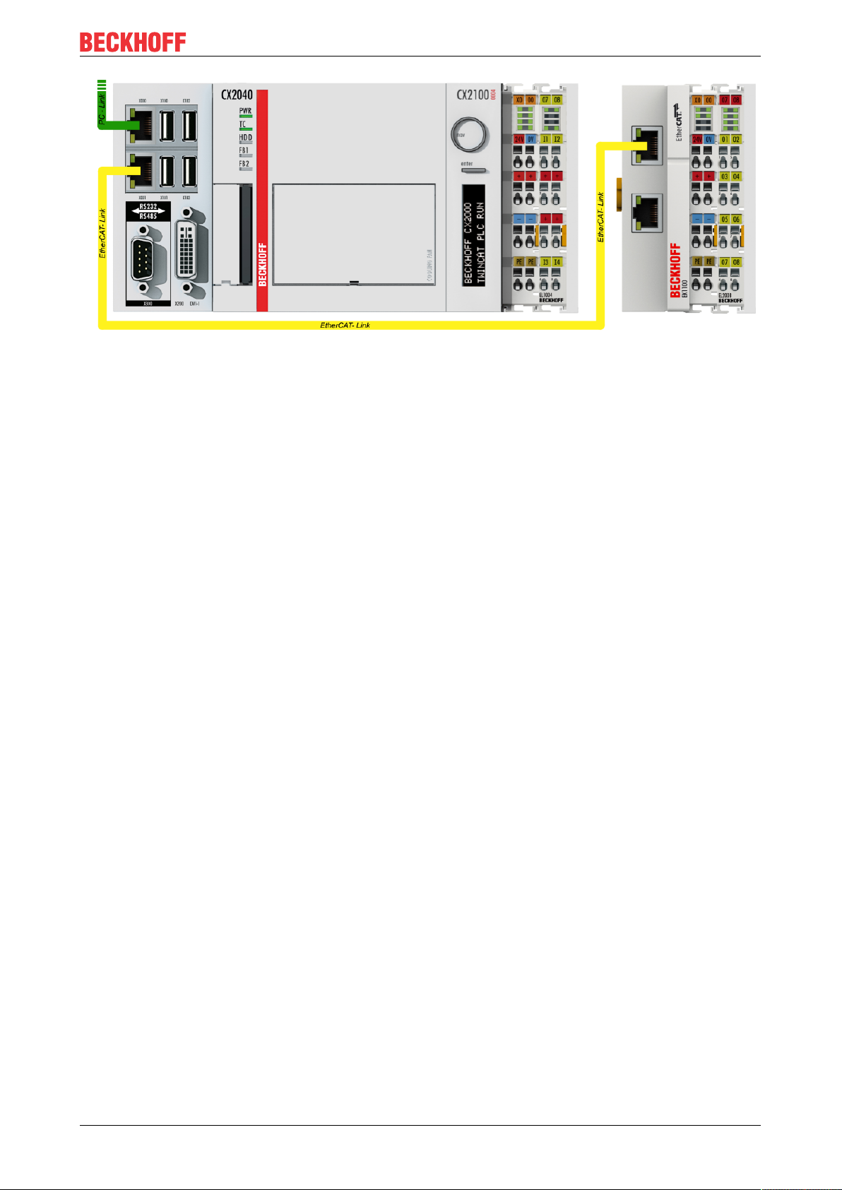
TwinCAT2 and TwinCAT3:
• Control system (PLC) CX2040 including CX2100-0004 power supply unit
• Connected to the CX2040 on the right (E-bus):
EL1004 (4-channel digital input terminal 24VDC)
• Linked via the X001 port (RJ-45): EK1100 EtherCAT Coupler
• Connected to the EK1100 EtherCAT coupler on the right (E-bus):
EL2008 (8-channel digital output terminal 24VDC;0.5A)
• (Optional via X000: a link to an external PC for the user interface)
ELX3152 and ELX315842 Version: 2.1.0
Page 43
Parameterization and programming
Fig.32: Control configuration with Embedded PC, input (EL1004) and output (EL2008)
Note that all combinations of a configuration are possible; for example, the EL1004 terminal could also be
connected after the coupler, or the EL2008 terminal could additionally be connected to the CX2040 on the
right, in which case the EK1100 coupler wouldn’t be necessary.
ELX3152 and ELX3158 43Version: 2.1.0
Page 44

Parameterization and programming
5.1.1 TwinCAT 2
Startup
TwinCAT basically uses two user interfaces: the TwinCAT System Manager for communication with the
electromechanical components and TwinCAT PLC Control for the development and compilation of a
controller. The starting point is the TwinCAT System Manager.
After successful installation of the TwinCAT system on the PC to be used for development, the TwinCAT2
System Manager displays the following user interface after startup:
Fig.33: Initial TwinCAT2 user interface
Generally, TwinCAT can be used in local or remote mode. Once the TwinCAT system including the user
interface (standard) is installed on the respective PLC, TwinCAT can be used in local mode and thereby the
next step is “Insert Device [}46]”.
If the intention is to address the TwinCAT runtime environment installed on a PLC as development
environment remotely from another system, the target system must be made known first. In the menu under
“Actions” → “Choose Target System...”, via the symbol “ ” or the “F8” key, open the following window:
ELX3152 and ELX315844 Version: 2.1.0
Page 45

Parameterization and programming
Fig.34: Selection of the target system
Use “Search (Ethernet)...” to enter the target system. Thus a next dialog opens to either:
• enter the known computer name after “Enter Host Name / IP:” (as shown in red)
• perform a “Broadcast Search” (if the exact computer name is not known)
• enter the known computer IP or AmsNetID.
Fig.35: Specify the PLC for access by the TwinCAT System Manager: selection of the target system
Once the target system has been entered, it is available for selection as follows (a password may have to be
entered):
After confirmation with “OK” the target system can be accessed via the System Manager.
ELX3152 and ELX3158 45Version: 2.1.0
Page 46

Parameterization and programming
Adding devices
In the configuration tree of the TwinCAT2 System Manager user interface on the left, select “I/ODevices”
and then right-click to open a context menu and select “ScanDevices…”, or start the action in the menu bar
via . The TwinCAT System Manager may first have to be set to “Configmode” via or via menu
“Actions” → “Set/Reset TwinCAT to Config Mode…” (Shift + F4).
Fig.36: Select “Scan Devices...”
Confirm the warning message, which follows, and select “EtherCAT” in the dialog:
Fig.37: Automatic detection of I/O devices: selection the devices to be integrated
Confirm the message “Find new boxes”, in order to determine the terminals connected to the devices. “Free
Run” enables manipulation of input and output values in “Config mode” and should also be acknowledged.
Based on the sample configuration [}42] described at the beginning of this section, the result is as follows:
ELX3152 and ELX315846 Version: 2.1.0
Page 47

Parameterization and programming
Fig.38: Mapping of the configuration in the TwinCAT2 System Manager
The whole process consists of two stages, which may be performed separately (first determine the devices,
then determine the connected elements such as boxes, terminals, etc.). A scan can also be initiated by
selecting “Device ...” from the context menu, which then reads the elements present in the configuration
below:
Fig.39: Reading of individual terminals connected to a device
This functionality is useful if the actual configuration is modified at short notice.
Programming and integrating the PLC
TwinCAT PLC Control is the development environment for the creation of the controller in different program
environments: TwinCAT PLC Control supports all languages described in IEC 61131-3. There are two textbased languages and three graphical languages.
• Text-based languages
◦ Instruction List (IL)
ELX3152 and ELX3158 47Version: 2.1.0
Page 48

Parameterization and programming
◦ Structured Text (ST)
• Graphical languages
◦ Function Block Diagram (FBD)
◦ Ladder Diagram (LD)
◦ The Continuous Function Chart Editor (CFC)
◦ Sequential Function Chart (SFC)
The following section refers to Structured Text (ST).
After starting TwinCAT PLC Control, the following user interface is shown for an initial project:
Fig.40: TwinCAT PLC Control after startup
Sample variables and a sample program have been created and stored under the name “PLC_example.pro”:
ELX3152 and ELX315848 Version: 2.1.0
Page 49

Parameterization and programming
Fig.41: Sample program with variables after a compile process (without variable integration)
Warning 1990 (missing “VAR_CONFIG”) after a compile process indicates that the variables defined as
external (with the ID “AT%I*” or “AT%Q*”) have not been assigned. After successful compilation, TwinCAT
PLC Control creates a “*.tpy” file in the directory in which the project was stored. This file (“*.tpy”) contains
variable assignments and is not known to the System Manager, hence the warning. Once the System
Manager has been notified, the warning no longer appears.
First, integrate the TwinCAT PLC Control project in the System Manager via the context menu of the PLC
configuration; right-click and select “Append PLC Project…”:
Fig.42: Appending the TwinCAT PLC Control project
ELX3152 and ELX3158 49Version: 2.1.0
Page 50

Parameterization and programming
Select the PLC configuration “PLC_example.tpy” in the browser window that opens. The project including the
two variables identified with “AT” are then integrated in the configuration tree of the System Manager:
Fig.43: PLC project integrated in the PLC configuration of the System Manager
The two variables “bEL1004_Ch4” and “nEL2008_value” can now be assigned to certain process objects of
the I/O configuration.
Assigning variables
Open a window for selecting a suitable process object (PDO) via the context menu of a variable of the
integrated project “PLC_example” and via “Modify Link...” “Standard”:
Fig.44: Creating the links between PLC variables and process objects
In the window that opens, the process object for the variable “bEL1004_Ch4” of type BOOL can be selected
from the PLC configuration tree:
ELX3152 and ELX315850 Version: 2.1.0
Page 51

Parameterization and programming
Fig.45: Selecting PDO of type BOOL
According to the default setting, certain PDO objects are now available for selection. In this sample the input
of channel 4 of the EL1004 terminal is selected for linking. In contrast, the checkbox “All types” must be
ticked for creating the link for the output variables, in order to allocate a set of eight separate output bits to a
byte variable. The following diagram shows the whole process:
Fig.46: Selecting several PDOs simultaneously: activate “Continuous” and “All types”
Note that the “Continuous” checkbox was also activated. This is designed to allocate the bits contained in the
byte of the variable “nEL2008_value” sequentially to all eight selected output bits of the EL2008 terminal. In
this way it is possible to subsequently address all eight outputs of the terminal in the program with a byte
corresponding to bit 0 for channel 1 to bit 7 for channel 8 of the PLC. A special symbol ( ) at the yellow or
red object of the variable indicates that a link exists. The links can also be checked by selecting a “Goto Link
Variable” from the context menu of a variable. The object opposite, in this case the PDO, is automatically
selected:
ELX3152 and ELX3158 51Version: 2.1.0
Page 52

Parameterization and programming
Fig.47: Application of a “Goto Link” variable, using “MAIN.bEL1004_Ch4” as a sample
The process of assigning variables to the PDO is completed via the menu selection “Actions” → “Generate
Mappings”, key Ctrl+M or by clicking on the symbol in the menu.
This can be visualized in the configuration:
The process of creating links can also take place in the opposite direction, i.e. starting with individual PDOs
to variable. However, in this example it would then not be possible to select all output bits for the EL2008,
since the terminal only makes individual digital outputs available. If a terminal has a byte, word, integer or
similar PDO, it is possible to allocate this a set of bit-standardized variables (type “BOOL”). Here, too, a
“Goto Link Variable” from the context menu of a PDO can be executed in the other direction, so that the
respective PLC instance can then be selected.
Activation of the configuration
The allocation of PDO to PLC variables has now established the connection from the controller to the inputs
and outputs of the terminals. The configuration can now be activated. First, the configuration can be verified
via (or via “Actions” → “Check Configuration”). If no error is present, the configuration can be
activated via (or via “Actions” → “Activate Configuration…”) to transfer the System Manager settings
to the runtime system. Confirm the messages “Old configurations are overwritten!” and “Restart TwinCAT
system in Run mode” with “OK”.
A few seconds later the real-time status is displayed at the bottom right in the System Manager.
The PLC system can then be started as described below.
Starting the controller
Starting from a remote system, the PLC control has to be linked with the Embedded PC over Ethernet via
“Online” → “Choose Run-Time System…”:
ELX3152 and ELX315852 Version: 2.1.0
Page 53

Parameterization and programming
Fig.48: Choose target system (remote)
In this sample “Runtime system 1 (port 801)” is selected and confirmed. Link the PLC with the real-time
system via menu option “Online” → “Login”, the F11 key or by clicking on the symbol .The control
program can then be loaded for execution. This results in the message “No program on the controller!
Should the new program be loaded?”, which should be acknowledged with “Yes”. The runtime environment
is ready for the program start:
ELX3152 and ELX3158 53Version: 2.1.0
Page 54

Parameterization and programming
Fig.49: PLC Control logged in, ready for program startup
The PLC can now be started via “Online” → “Run”, F5 key or .
5.1.2 TwinCAT 3
Startup
TwinCAT makes the development environment areas available together with Microsoft Visual Studio: after
startup, the project folder explorer appears on the left in the general window area (cf. “TwinCAT System
Manager” of TwinCAT2) for communication with the electromechanical components.
After successful installation of the TwinCAT system on the PC to be used for development, TwinCAT3
(shell) displays the following user interface after startup:
ELX3152 and ELX315854 Version: 2.1.0
Page 55

Parameterization and programming
Fig.50: Initial TwinCAT3 user interface
First create a new project via (or under “File”→“New”→ “Project…”). In the
following dialog make the corresponding entries as required (as shown in the diagram):
Fig.51: Create new TwinCAT project
The new project is then available in the project folder explorer:
ELX3152 and ELX3158 55Version: 2.1.0
Page 56

Parameterization and programming
Fig.52: New TwinCAT3 project in the project folder explorer
Generally, TwinCAT can be used in local or remote mode. Once the TwinCAT system including the user
interface (standard) is installed on the respective PLC, TwinCAT can be used in local mode and thereby the
next step is “Insert Device [}57]”.
If the intention is to address the TwinCAT runtime environment installed on a PLC as development
environment remotely from another system, the target system must be made known first. Via the symbol in
the menu bar:
expand the pull-down menu:
and open the following window:
Fig.53: Selection dialog: Choose the target system
ELX3152 and ELX315856 Version: 2.1.0
Page 57

Parameterization and programming
Use “Search (Ethernet)...” to enter the target system. Thus a next dialog opens to either:
• enter the known computer name after “Enter Host Name / IP:” (as shown in red)
• perform a “Broadcast Search” (if the exact computer name is not known)
• enter the known computer IP or AmsNetID.
Fig.54: Specify the PLC for access by the TwinCAT System Manager: selection of the target system
Once the target system has been entered, it is available for selection as follows (a password may have to be
entered):
After confirmation with “OK” the target system can be accessed via the Visual Studio shell.
Adding devices
In the project folder explorer of the Visual Studio shell user interface on the left, select “Devices” within
element “I/O”, then right-click to open a context menu and select “Scan” or start the action via in the
menu bar. The TwinCAT System Manager may first have to be set to “Config mode” via or via the
menu “TwinCAT” → “Restart TwinCAT (Config mode)”.
Fig.55: Select “Scan”
Confirm the warning message, which follows, and select “EtherCAT” in the dialog:
ELX3152 and ELX3158 57Version: 2.1.0
Page 58

Parameterization and programming
Fig.56: Automatic detection of I/O devices: selection the devices to be integrated
Confirm the message “Find new boxes”, in order to determine the terminals connected to the devices. “Free
Run” enables manipulation of input and output values in “Config mode” and should also be acknowledged.
Based on the sample configuration [}42] described at the beginning of this section, the result is as follows:
Fig.57: Mapping of the configuration in VS shell of the TwinCAT3 environment
The whole process consists of two stages, which may be performed separately (first determine the devices,
then determine the connected elements such as boxes, terminals, etc.). A scan can also be initiated by
selecting “Device ...” from the context menu, which then reads the elements present in the configuration
below:
ELX3152 and ELX315858 Version: 2.1.0
Page 59

Parameterization and programming
Fig.58: Reading of individual terminals connected to a device
This functionality is useful if the actual configuration is modified at short notice.
Programming the PLC
TwinCAT PLC Control is the development environment for the creation of the controller in different program
environments: TwinCAT PLC Control supports all languages described in IEC 61131-3. There are two textbased languages and three graphical languages.
• Text-based languages
◦ Instruction List (IL)
◦ Structured Text (ST)
• Graphical languages
◦ Function Block Diagram (FBD)
◦ Ladder Diagram (LD)
◦ The Continuous Function Chart Editor (CFC)
◦ Sequential Function Chart (SFC)
The following section refers to Structured Text (ST).
In order to create a programming environment, a PLC subproject is added to the project sample via the
context menu of “PLC” in the project folder explorer by selecting “Add New Item….”:
ELX3152 and ELX3158 59Version: 2.1.0
Page 60

Parameterization and programming
Fig.59: Adding the programming environment in “PLC”
In the dialog that opens select “Standard PLC project” and enter “PLC_example” as project name, for
example, and select a corresponding directory:
Fig.60: Specifying the name and directory for the PLC programming environment
The “Main” program, which already exists by selecting “Standard PLC project”, can be opened by doubleclicking on “PLC_example_project” in “POUs”. The following user interface is shown for an initial project:
ELX3152 and ELX315860 Version: 2.1.0
Page 61

Parameterization and programming
Fig.61: Initial “Main” program of the standard PLC project
To continue, sample variables and a sample program have now been created:
ELX3152 and ELX3158 61Version: 2.1.0
Page 62

Parameterization and programming
Fig.62: Sample program with variables after a compile process (without variable integration)
The control program is now created as a project folder, followed by the compile process:
Fig.63: Start program compilation
The following variables, identified in the ST/ PLC program with “AT%”, are then available in under
“Assignments” in the project folder explorer:
Assigning variables
Via the menu of an instance - variables in the “PLC” context, use the “Modify Link…” option to open a
window for selecting a suitable process object (PDO) for linking:
ELX3152 and ELX315862 Version: 2.1.0
Page 63

Parameterization and programming
Fig.64: Creating the links between PLC variables and process objects
In the window that opens, the process object for the variable “bEL1004_Ch4” of type BOOL can be selected
from the PLC configuration tree:
Fig.65: Selecting PDO of type BOOL
According to the default setting, certain PDO objects are now available for selection. In this sample the input
of channel 4 of the EL1004 terminal is selected for linking. In contrast, the checkbox “All types” must be
ticked for creating the link for the output variables, in order to allocate a set of eight separate output bits to a
byte variable. The following diagram shows the whole process:
ELX3152 and ELX3158 63Version: 2.1.0
Page 64

Parameterization and programming
Fig.66: Selecting several PDOs simultaneously: activate “Continuous” and “All types”
Note that the “Continuous” checkbox was also activated. This is designed to allocate the bits contained in the
byte of the variable “nEL2008_value” sequentially to all eight selected output bits of the EL2008 terminal. In
this way it is possible to subsequently address all eight outputs of the terminal in the program with a byte
corresponding to bit 0 for channel 1 to bit 7 for channel 8 of the PLC. A special symbol ( ) at the yellow or
red object of the variable indicates that a link exists. The links can also be checked by selecting a “Goto Link
Variable” from the context menu of a variable. The object opposite, in this case the PDO, is automatically
selected:
Fig.67: Application of a “Goto Link” variable, using “MAIN.bEL1004_Ch4” as a sample
The process of creating links can also take place in the opposite direction, i.e. starting with individual PDOs
to variable. However, in this example it would then not be possible to select all output bits for the EL2008,
since the terminal only makes individual digital outputs available. If a terminal has a byte, word, integer or
ELX3152 and ELX315864 Version: 2.1.0
Page 65

Parameterization and programming
similar PDO, it is possible to allocate this a set of bit-standardized variables (type “BOOL”). Here, too, a
“Goto Link Variable” from the context menu of a PDO can be executed in the other direction, so that the
respective PLC instance can then be selected.
Note on the type of variable assignment
The following type of variable assignment can only be used from TwinCAT version V3.1.4024.4 onwards and is only available for terminals with a microcontroller.
In TwinCAT it is possible to create a structure from the mapped process data of a terminal. An instance of
this structure can then be created in the PLC, so it is possible to access the process data directly from the
PLC without having to declare own variables.
The procedure for the EL3001 1-channel analog input terminal -10...+10V is shown as an example.
1. First the required process data must be selected in the “Process data” tab in TwinCAT.
2. After that, the PLC data type must be generated in the tab “PLC” via the check box.
3. The data type in the “Data Type” field can then be copied using the “Copy” button.
Fig.68: Creating a PLC data type
4. An instance of the data structure of the copied data type must then be created in the PLC.
Fig.69: Instance_of_struct
5. Then the project folder must be created. This can be done either via the key combination “CTRL +
Shift + B” or via the “Build” tab in TwinCAT.
6. The structure in the “PLC” tab of the terminal must then be linked to the created instance.
ELX3152 and ELX3158 65Version: 2.1.0
Page 66

Parameterization and programming
Fig.70: Linking the structure
7. In the PLC the process data can then be read or written via the structure in the program code.
Fig.71: Reading a variable from the structure of the process data
Activation of the configuration
The allocation of PDO to PLC variables has now established the connection from the controller to the inputs
and outputs of the terminals. The configuration can now be activated with or via the menu under
“TwinCAT” in order to transfer settings of the development environment to the runtime system. Confirm the
messages “Old configurations are overwritten!” and “Restart TwinCAT system in Run mode” with “OK”. The
corresponding assignments can be seen in the project folder explorer:
A few seconds later the corresponding status of the Run mode is displayed in the form of a rotating symbol
at the bottom right of the VS shell development environment. The PLC system can then be started as
described below.
ELX3152 and ELX315866 Version: 2.1.0
Page 67

Parameterization and programming
Starting the controller
Select the menu option “PLC” → “Login” or click on to link the PLC with the real-time system and load
the control program for execution. This results in the message No program on the controller! Should the new
program be loaded?, which should be acknowledged with “Yes”. The runtime environment is ready for
program start by click on symbol , the “F5” key or via “PLC” in the menu selecting “Start”. The started
programming environment shows the runtime values of individual variables:
Fig.72: TwinCAT development environment (VS shell): logged-in, after program startup
The two operator control elements for stopping and logout result in the required action
(accordingly also for stop “Shift + F5”, or both actions can be selected via the PLC menu).
5.2 TwinCAT Development Environment
The Software for automation TwinCAT (The Windows Control and Automation Technology) will be
distinguished into:
• TwinCAT2: System Manager (Configuration) & PLC Control (Programming)
• TwinCAT3: Enhancement of TwinCAT2 (Programming and Configuration takes place via a common
Development Environment)
Details:
• TwinCAT2:
◦ Connects I/O devices to tasks in a variable-oriented manner
◦ Connects tasks to tasks in a variable-oriented manner
◦ Supports units at the bit level
◦ Supports synchronous or asynchronous relationships
◦ Exchange of consistent data areas and process images
◦ Datalink on NT - Programs by open Microsoft Standards (OLE, OCX, ActiveX, DCOM+, etc.)
ELX3152 and ELX3158 67Version: 2.1.0
Page 68

Parameterization and programming
◦ Integration of IEC 61131-3-Software-SPS, Software- NC and Software-CNC within Windows
NT/2000/XP/Vista, Windows 7, NT/XP Embedded, CE
◦ Interconnection to all common fieldbusses
◦ More…
Additional features:
• TwinCAT3 (eXtended Automation):
◦ Visual-Studio®-Integration
◦ Choice of the programming language
◦ Supports object orientated extension of IEC 61131-3
◦ Usage of C/C++ as programming language for real time applications
◦ Connection to MATLAB®/Simulink®
◦ Open interface for expandability
◦ Flexible run-time environment
◦ Active support of Multi-Core- und 64-Bit-Operatingsystem
◦ Automatic code generation and project creation with the TwinCAT Automation Interface
◦ More…
Within the following sections commissioning of the TwinCAT Development Environment on a PC System for
the control and also the basically functions of unique control elements will be explained.
Please see further information to TwinCAT2 and TwinCAT3 at http://infosys.beckhoff.com.
5.2.1 Installation of the TwinCAT real-time driver
In order to assign real-time capability to a standard Ethernet port of an IPC controller, the Beckhoff real-time
driver has to be installed on this port under Windows.
This can be done in several ways. One option is described here.
In the System Manager call up the TwinCAT overview of the local network interfaces via Options → Show
Real Time Ethernet Compatible Devices.
Fig.73: System Manager “Options” (TwinCAT2)
This have to be called up by the Menü “TwinCAT” within the TwinCAT3 environment:
Fig.74: Call up under VS Shell (TwinCAT3)
ELX3152 and ELX315868 Version: 2.1.0
Page 69

Parameterization and programming
The following dialog appears:
Fig.75: Overview of network interfaces
Interfaces listed under “Compatible devices” can be assigned a driver via the “Install” button. A driver should
only be installed on compatible devices.
A Windows warning regarding the unsigned driver can be ignored.
Alternatively an EtherCAT-device can be inserted first of all as described in chapter Offline configuration
creation, section “Creating the EtherCAT device” [}78] in order to view the compatible ethernet ports via its
EtherCAT properties (tab “Adapter”, button “Compatible Devices…”):
Fig.76: EtherCAT device properties(TwinCAT2): click on “Compatible Devices…” of tab “Adapte””
TwinCAT 3: the properties of the EtherCAT device can be opened by double click on “Device .. (EtherCAT)”
within the Solution Explorer under “I/O”:
After the installation the driver appears activated in the Windows overview for the network interface
(Windows Start → System Properties → Network)
ELX3152 and ELX3158 69Version: 2.1.0
Page 70

Parameterization and programming
Fig.77: Windows properties of the network interface
A correct setting of the driver could be:
Fig.78: Exemplary correct driver setting for the Ethernet port
Other possible settings have to be avoided:
ELX3152 and ELX315870 Version: 2.1.0
Page 71

Parameterization and programming
Fig.79: Incorrect driver settings for the Ethernet port
ELX3152 and ELX3158 71Version: 2.1.0
Page 72

Parameterization and programming
IP address of the port used
IP address/DHCP
In most cases an Ethernet port that is configured as an EtherCAT device will not transport general
IP packets. For this reason and in cases where an EL6601 or similar devices are used it is useful to
specify a fixed IP address for this port via the “Internet Protocol TCP/IP” driver setting and to disable
DHCP. In this way the delay associated with the DHCP client for the Ethernet port assigning itself a
default IP address in the absence of a DHCP server is avoided. A suitable address space is
192.168.x.x, for example.
Fig.80: TCP/IP setting for the Ethernet port
ELX3152 and ELX315872 Version: 2.1.0
Page 73

Parameterization and programming
5.2.2 Notes regarding ESI device description
Installation of the latest ESI device description
The TwinCAT EtherCAT master/System Manager needs the device description files for the devices to be
used in order to generate the configuration in online or offline mode. The device descriptions are contained
in the so-called ESI files (EtherCAT Slave Information) in XML format. These files can be requested from the
respective manufacturer and are made available for download. An *.xml file may contain several device
descriptions.
The ESI files for Beckhoff EtherCAT devices are available on the Beckhoff website.
The ESI files should be stored in the TwinCAT installation directory.
Default settings:
• TwinCAT2: C:\TwinCAT\IO\EtherCAT
• TwinCAT3: C:\TwinCAT\3.1\Config\Io\EtherCAT
The files are read (once) when a new System Manager window is opened, if they have changed since the
last time the System Manager window was opened.
A TwinCAT installation includes the set of Beckhoff ESI files that was current at the time when the TwinCAT
build was created.
For TwinCAT2.11/TwinCAT3 and higher, the ESI directory can be updated from the System Manager, if the
programming PC is connected to the Internet; by
• TwinCAT2: Option → “Update EtherCAT Device Descriptions”
• TwinCAT3: TwinCAT → EtherCAT Devices → “Update Device Descriptions (via ETG Website)…”
The TwinCAT ESI Updater [}77] is available for this purpose.
ESI
The *.xml files are associated with *.xsd files, which describe the structure of the ESI XML files. To
update the ESI device descriptions, both file types should therefore be updated.
Device differentiation
EtherCAT devices/slaves are distinguished by four properties, which determine the full device identifier. For
example, the device identifier EL2521-0025-1018 consists of:
• family key “EL”
• name “2521”
• type “0025”
• and revision “1018”
Fig.81: Identifier structure
The order identifier consisting of name + type (here: EL2521-0010) describes the device function. The
revision indicates the technical progress and is managed by Beckhoff. In principle, a device with a higher
revision can replace a device with a lower revision, unless specified otherwise, e.g. in the documentation.
Each revision has its own ESI description. See further notes.
ELX3152 and ELX3158 73Version: 2.1.0
Page 74

Parameterization and programming
Online description
If the EtherCAT configuration is created online through scanning of real devices (see section Online setup)
and no ESI descriptions are available for a slave (specified by name and revision) that was found, the
System Manager asks whether the description stored in the device should be used. In any case, the System
Manager needs this information for setting up the cyclic and acyclic communication with the slave correctly.
Fig.82: OnlineDescription information window (TwinCAT2)
In TwinCAT3 a similar window appears, which also offers the Web update:
Fig.83: Information window OnlineDescription (TwinCAT3)
If possible, the Yes is to be rejected and the required ESI is to be requested from the device manufacturer.
After installation of the XML/XSD file the configuration process should be repeated.
NOTE
Changing the “usual” configuration through a scan
ü If a scan discovers a device that is not yet known to TwinCAT, distinction has to be made between two
cases. Taking the example here of the EL2521-0000 in the revision 1019
a) no ESI is present for the EL2521-0000 device at all, either for the revision 1019 or for an older revision.
The ESI must then be requested from the manufacturer (in this case Beckhoff).
b) an ESI is present for the EL2521-0000 device, but only in an older revision, e.g. 1018 or 1017.
In this case an in-house check should first be performed to determine whether the spare parts stock allows the integration of the increased revision into the configuration at all. A new/higher revision usually
also brings along new features. If these are not to be used, work can continue without reservations with
the previous revision 1018 in the configuration. This is also stated by the Beckhoff compatibility rule.
Refer in particular to the chapter “General notes on the use of Beckhoff EtherCAT IO components” and for
manual configuration to the chapter “Offline configuration creation [}78]”.
If the OnlineDescription is used regardless, the System Manager reads a copy of the device description from
the EEPROM in the EtherCAT slave. In complex slaves the size of the EEPROM may not be sufficient for the
complete ESI, in which case the ESI would be incomplete in the configurator. Therefore it’s recommended
using an offline ESI file with priority in such a case.
The System Manager creates for online recorded device descriptions a new file
“OnlineDescription0000...xml” in its ESI directory, which contains all ESI descriptions that were read online.
ELX3152 and ELX315874 Version: 2.1.0
Page 75

Parameterization and programming
Fig.84: File OnlineDescription.xml created by the System Manager
Is a slave desired to be added manually to the configuration at a later stage, online created slaves are
indicated by a prepended symbol “>” in the selection list (see Figure Indication of an online recorded ESI of
EL2521 as an example).
Fig.85: Indication of an online recorded ESI of EL2521 as an example
If such ESI files are used and the manufacturer's files become available later, the file OnlineDescription.xml
should be deleted as follows:
• close all System Manager windows
• restart TwinCAT in Config mode
• delete “OnlineDescription0000...xml”
• restart TwinCAT System Manager
This file should not be visible after this procedure, if necessary press <F5> to update
OnlineDescription for TwinCAT3.x
In addition to the file described above “OnlineDescription0000...xml”, a so called EtherCAT cache
with new discovered devices is created by TwinCAT3.x, e.g. under Windows 7:
(Please note the language settings of the OS!)
You have to delete this file, too.
Faulty ESI file
If an ESI file is faulty and the System Manager is unable to read it, the System Manager brings up an
information window.
Fig.86: Information window for faulty ESI file (left: TwinCAT2; right: TwinCAT3)
ELX3152 and ELX3158 75Version: 2.1.0
Page 76

Parameterization and programming
Reasons may include:
• Structure of the *.xml does not correspond to the associated *.xsd file → check your schematics
• Contents cannot be translated into a device description → contact the file manufacturer
ELX3152 and ELX315876 Version: 2.1.0
Page 77

Parameterization and programming
5.2.3 TwinCAT ESI Updater
For TwinCAT2.11 and higher, the System Manager can search for current Beckhoff ESI files automatically, if
an online connection is available:
Fig.87: Using the ESI Updater (>= TwinCAT2.11)
The call up takes place under:
“Options” → “Update EtherCAT Device Descriptions”
Selection under TwinCAT3:
Fig.88: Using the ESI Updater (TwinCAT3)
The ESI Updater (TwinCAT3) is a convenient option for automatic downloading of ESI data provided by
EtherCAT manufacturers via the Internet into the TwinCAT directory (ESI = EtherCAT slave information).
TwinCAT accesses the central ESI ULR directory list stored at ETG; the entries can then be viewed in the
Updater dialog, although they cannot be changed there.
The call up takes place under:
“TwinCAT” → “EtherCAT Devices” → “Update Device Description (via ETG Website)…”.
5.2.4 Distinction between Online and Offline
The distinction between online and offline refers to the presence of the actual I/O environment (drives,
terminals, EJ-modules). If the configuration is to be prepared in advance of the system configuration as a
programming system, e.g. on a laptop, this is only possible in “Offline configuration” mode. In this case all
components have to be entered manually in the configuration, e.g. based on the electrical design.
If the designed control system is already connected to the EtherCAT system and all components are
energised and the infrastructure is ready for operation, the TwinCAT configuration can simply be generated
through “scanning” from the runtime system. This is referred to as online configuration.
In any case, during each startup the EtherCAT master checks whether the slaves it finds match the
configuration. This test can be parameterised in the extended slave settings. Refer to note “Installation of
the latest ESI-XML device description” [}73].
For preparation of a configuration:
• the real EtherCAT hardware (devices, couplers, drives) must be present and installed
• the devices/modules must be connected via EtherCAT cables or in the terminal/ module strand in the
same way as they are intended to be used later
ELX3152 and ELX3158 77Version: 2.1.0
Page 78

Parameterization and programming
• the devices/modules be connected to the power supply and ready for communication
• TwinCAT must be in CONFIG mode on the target system.
The online scan process consists of:
• detecting the EtherCAT device [}83] (Ethernet port at the IPC)
• detecting the connected EtherCAT devices [}84]. This step can be carried out independent of the
preceding step
• troubleshooting [}87]
The scan with existing configuration [}88] can also be carried out for comparison.
5.2.5 OFFLINE configuration creation
Creating the EtherCAT device
Create an EtherCAT device in an empty System Manager window.
Fig.89: Append EtherCAT device (left: TwinCAT2; right: TwinCAT3)
Select type “EtherCAT” for an EtherCAT I/O application with EtherCAT slaves. For the present publisher/
subscriber service in combination with an EL6601/EL6614 terminal select “EtherCAT Automation Protocol
via EL6601”.
Fig.90: Selecting the EtherCAT connection (TwinCAT2.11, TwinCAT3)
Then assign a real Ethernet port to this virtual device in the runtime system.
Fig.91: Selecting the Ethernet port
ELX3152 and ELX315878 Version: 2.1.0
Page 79

Parameterization and programming
This query may appear automatically when the EtherCAT device is created, or the assignment can be set/
modified later in the properties dialog; see Fig. “EtherCAT device properties (TwinCAT2)”.
Fig.92: EtherCAT device properties (TwinCAT2)
TwinCAT 3: the properties of the EtherCAT device can be opened by double click on “Device .. (EtherCAT)”
within the Solution Explorer under “I/O”:
Selecting the Ethernet port
Ethernet ports can only be selected for EtherCAT devices for which the TwinCAT real-time driver is
installed. This has to be done separately for each port. Please refer to the respective installation
page [}68].
Defining EtherCAT slaves
Further devices can be appended by right-clicking on a device in the configuration tree.
Fig.93: Appending EtherCAT devices (left: TwinCAT2; right: TwinCAT3)
The dialog for selecting a new device opens. Only devices for which ESI files are available are displayed.
Only devices are offered for selection that can be appended to the previously selected device. Therefore the
physical layer available for this port is also displayed (Fig. “Selection dialog for new EtherCAT device”, A). In
the case of cable-based Fast-Ethernet physical layer with PHY transfer, then also only cable-based devices
are available, as shown in Fig. “Selection dialog for new EtherCAT device”. If the preceding device has
several free ports (e.g. EK1122 or EK1100), the required port can be selected on the right-hand side (A).
Overview of physical layer
• “Ethernet”: cable-based 100BASE-TX: EK couplers, EP boxes, devices with RJ45/M8/M12 connector
ELX3152 and ELX3158 79Version: 2.1.0
Page 80

Parameterization and programming
• “E-Bus”: LVDS “terminal bus”, “EJ-module”: EL/ES terminals, various modular modules
The search field facilitates finding specific devices (since TwinCAT2.11 or TwinCAT3).
Fig.94: Selection dialog for new EtherCAT device
By default only the name/device type is used as selection criterion. For selecting a specific revision of the
device the revision can be displayed as “Extended Information”.
Fig.95: Display of device revision
In many cases several device revisions were created for historic or functional reasons, e.g. through
technological advancement. For simplification purposes (see Fig. “Selection dialog for new EtherCAT
device”) only the last (i.e. highest) revision and therefore the latest state of production is displayed in the
selection dialog for Beckhoff devices. To show all device revisions available in the system as ESI
descriptions tick the “Show Hidden Devices” check box, see Fig. “Display of previous revisions”.
ELX3152 and ELX315880 Version: 2.1.0
Page 81
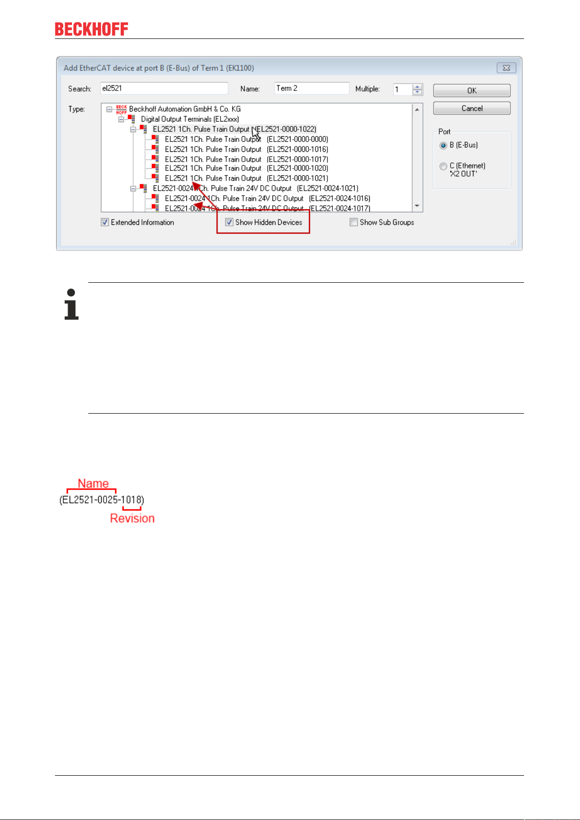
Fig.96: Display of previous revisions
Device selection based on revision, compatibility
The ESI description also defines the process image, the communication type between master and
slave/device and the device functions, if applicable. The physical device (firmware, if available) has
to support the communication queries/settings of the master. This is backward compatible, i.e.
newer devices (higher revision) should be supported if the EtherCAT master addresses them as an
older revision. The following compatibility rule of thumb is to be assumed for Beckhoff EtherCAT
Terminals/ Boxes/ EJ-modules:
device revision in the system >= device revision in the configuration
This also enables subsequent replacement of devices without changing the configuration (different
specifications are possible for drives).
Parameterization and programming
Example
If an EL2521-0025-1018 is specified in the configuration, an EL2521-0025-1018 or higher (-1019, -1020) can
be used in practice.
Fig.97: Name/revision of the terminal
If current ESI descriptions are available in the TwinCAT system, the last revision offered in the selection
dialog matches the Beckhoff state of production. It is recommended to use the last device revision when
creating a new configuration, if current Beckhoff devices are used in the real application. Older revisions
should only be used if older devices from stock are to be used in the application.
In this case the process image of the device is shown in the configuration tree and can be parameterized as
follows: linking with the task, CoE/DC settings, plug-in definition, startup settings, ...
ELX3152 and ELX3158 81Version: 2.1.0
Page 82

Parameterization and programming
Fig.98: EtherCAT terminal in the TwinCAT tree (left: TwinCAT2; right: TwinCAT3)
ELX3152 and ELX315882 Version: 2.1.0
Page 83

Parameterization and programming
5.2.6 ONLINE configuration creation
Detecting/scanning of the EtherCAT device
The online device search can be used if the TwinCAT system is in CONFIG mode. This can be indicated by
a symbol right below in the information bar:
• on TwinCAT2 by a blue display “Config Mode” within the System Manager window: .
• on TwinCAT3 within the user interface of the development environment by a symbol .
TwinCAT can be set into this mode:
• TwinCAT2: by selection of in the Menubar or by “Actions” → “Set/Reset TwinCATtoConfig
Mode…”
• TwinCAT3: by selection of in the Menubar or by “TwinCAT” → “RestartTwinCAT(ConfigMode)”
Online scanning in Config mode
The online search is not available in RUN mode (production operation). Note the differentiation between TwinCAT programming system and TwinCAT target system.
The TwinCAT2 icon ( ) or TwinCAT3 icon ( ) within the Windows-Taskbar always shows the
TwinCAT mode of the local IPC. Compared to that, the System Manager window of TwinCAT2 or the user
interface of TwinCAT3 indicates the state of the target system.
Fig.99: Differentiation local/target system (left: TwinCAT2; right: TwinCAT3)
Right-clicking on “I/O Devices” in the configuration tree opens the search dialog.
Fig.100: Scan Devices (left: TwinCAT2; right: TwinCAT3)
This scan mode attempts to find not only EtherCAT devices (or Ethernet ports that are usable as such), but
also NOVRAM, fieldbus cards, SMB etc. However, not all devices can be found automatically.
Fig.101: Note for automatic device scan (left: TwinCAT2; right: TwinCAT3)
ELX3152 and ELX3158 83Version: 2.1.0
Page 84

Parameterization and programming
Ethernet ports with installed TwinCAT real-time driver are shown as “RT Ethernet” devices. An EtherCAT
frame is sent to these ports for testing purposes. If the scan agent detects from the response that an
EtherCAT slave is connected, the port is immediately shown as an “EtherCAT Device” .
Fig.102: Detected Ethernet devices
Via respective checkboxes devices can be selected (as illustrated in Fig. “Detected Ethernet devices” e.g.
Device 3 and Device 4 were chosen). After confirmation with “OK” a device scan is suggested for all selected
devices, see Fig.: “Scan query after automatic creation of an EtherCAT device”.
Selecting the Ethernet port
Ethernet ports can only be selected for EtherCAT devices for which the TwinCAT real-time driver is
installed. This has to be done separately for each port. Please refer to the respective installation
page [}68].
Detecting/Scanning the EtherCAT devices
Online scan functionality
During a scan the master queries the identity information of the EtherCAT slaves from the slave
EEPROM. The name and revision are used for determining the type. The respective devices are located in the stored ESI data and integrated in the configuration tree in the default state defined
there.
Fig.103: Example default state
NOTE
Slave scanning in practice in series machine production
The scanning function should be used with care. It is a practical and fast tool for creating an initial configuration as a basis for commissioning. In series machine production or reproduction of the plant, however, the
function should no longer be used for the creation of the configuration, but if necessary for comparison
[}88] with the defined initial configuration.Background: since Beckhoff occasionally increases the revision
version of the delivered products for product maintenance reasons, a configuration can be created by such
a scan which (with an identical machine construction) is identical according to the device list; however, the
respective device revision may differ from the initial configuration.
Example:
Company A builds the prototype of a machine B, which is to be produced in series later on. To do this the
prototype is built, a scan of the IO devices is performed in TwinCAT and the initial configuration “B.tsm” is
created. The EL2521-0025 EtherCAT terminal with the revision 1018 is located somewhere. It is thus built
into the TwinCAT configuration in this way:
ELX3152 and ELX315884 Version: 2.1.0
Page 85

Parameterization and programming
Fig.104: Installing EthetCAT terminal with revision -1018
Likewise, during the prototype test phase, the functions and properties of this terminal are tested by the
programmers/commissioning engineers and used if necessary, i.e. addressed from the PLC “B.pro” or the
NC. (the same applies correspondingly to the TwinCAT3 solution files).
The prototype development is now completed and series production of machine B starts, for which Beckhoff
continues to supply the EL2521-0025-0018. If the commissioning engineers of the series machine production
department always carry out a scan, a B configuration with the identical contents results again for each
machine. Likewise, A might create spare parts stores worldwide for the coming series-produced machines
with EL2521-0025-1018 terminals.
After some time Beckhoff extends the EL2521-0025 by a new feature C. Therefore the FW is changed,
outwardly recognizable by a higher FW version and a new revision -1019. Nevertheless the new device
naturally supports functions and interfaces of the predecessor version(s); an adaptation of “B.tsm” or even
“B.pro” is therefore unnecessary. The series-produced machines can continue to be built with “B.tsm” and
“B.pro”; it makes sense to perform a comparative scan [}88] against the initial configuration “B.tsm” in order
to check the built machine.
However, if the series machine production department now doesn’t use “B.tsm”, but instead carries out a
scan to create the productive configuration, the revision -1019 is automatically detected and built into the
configuration:
Fig.105: Detection of EtherCAT terminal with revision -1019
This is usually not noticed by the commissioning engineers. TwinCAT cannot signal anything either, since
virtually a new configuration is created. According to the compatibility rule, however, this means that no
EL2521-0025-1018 should be built into this machine as a spare part (even if this nevertheless works in the
vast majority of cases).
In addition, it could be the case that, due to the development accompanying production in company A, the
new feature C of the EL2521-0025-1019 (for example, an improved analog filter or an additional process
data for the diagnosis) is discovered and used without in-house consultation. The previous stock of spare
part devices are then no longer to be used for the new configuration “B2.tsm” created in this way. Þ if series
machine production is established, the scan should only be performed for informative purposes for
comparison with a defined initial configuration. Changes are to be made with care!
If an EtherCAT device was created in the configuration (manually or through a scan), the I/O field can be
scanned for devices/slaves.
Fig.106: Scan query after automatic creation of an EtherCAT device (left: TwinCAT2; right: TwinCAT3)
ELX3152 and ELX3158 85Version: 2.1.0
Page 86

Parameterization and programming
Fig.107: Manual triggering of a device scan on a specified EtherCAT device (left: TwinCAT2; right:
TwinCAT3)
In the System Manager (TwinCAT2) or the User Interface (TwinCAT3) the scan process can be monitored
via the progress bar at the bottom in the status bar.
Fig.108: Scan progressexemplary by TwinCAT2
The configuration is established and can then be switched to online state (OPERATIONAL).
Fig.109: Config/FreeRun query (left: TwinCAT2; right: TwinCAT3)
In Config/FreeRun mode the System Manager display alternates between blue and red, and the EtherCAT
device continues to operate with the idling cycle time of 4ms (default setting), even without active task (NC,
PLC).
Fig.110: Displaying of “Free Run” and “Config Mode” toggling right below in the status bar
Fig.111: TwinCAT can also be switched to this state by using a button (left: TwinCAT2; right: TwinCAT3)
The EtherCAT system should then be in a functional cyclic state, as shown in Fig. Online display example.
ELX3152 and ELX315886 Version: 2.1.0
Page 87

Parameterization and programming
Fig.112: Online display example
Please note:
• all slaves should be in OP state
• the EtherCAT master should be in “Actual State” OP
• “frames/sec” should match the cycle time taking into account the sent number of frames
• no excessive “LostFrames” or CRC errors should occur
The configuration is now complete. It can be modified as described under manual procedure [}78].
Troubleshooting
Various effects may occur during scanning.
• An unknown device is detected, i.e. an EtherCAT slave for which no ESI XML description is available.
In this case the System Manager offers to read any ESI that may be stored in the device. This case is
described in the chapter “Notes regarding ESI device description”.
• Device are not detected properly
Possible reasons include:
◦ faulty data links, resulting in data loss during the scan
◦ slave has invalid device description
The connections and devices should be checked in a targeted manner, e.g. via the emergency
scan.
Then re-run the scan.
Fig.113: Faulty identification
In the System Manager such devices may be set up as EK0000 or unknown devices. Operation is not
possible or meaningful.
ELX3152 and ELX3158 87Version: 2.1.0
Page 88

Parameterization and programming
Scan over existing Configuration
NOTE
Change of the configuration after comparison
With this scan (TwinCAT2.11 or 3.1) only the device properties vendor (manufacturer), device name and
revision are compared at present! A “ChangeTo” or “Copy” should only be carried out with care, taking into
consideration the Beckhoff IO compatibility rule (see above). The device configuration is then replaced by
the revision found; this can affect the supported process data and functions.
If a scan is initiated for an existing configuration, the actual I/O environment may match the configuration
exactly or it may differ. This enables the configuration to be compared.
Fig.114: Identical configuration (left: TwinCAT2; right: TwinCAT3)
If differences are detected, they are shown in the correction dialog, so that the user can modify the
configuration as required.
Fig.115: Correction dialog
It is advisable to tick the “Extended Information” check box to reveal differences in the revision.
ELX3152 and ELX315888 Version: 2.1.0
Page 89

Parameterization and programming
Color Explanation
green This EtherCAT slave matches the entry on the other side. Both type and revision match.
blue This EtherCAT slave is present on the other side, but in a different revision. This other revision can
have other default values for the process data as well as other/additional functions.
If the found revision is higher than the configured revision, the slave may be used provided
compatibility issues are taken into account.
If the found revision is lower than the configured revision, it is likely that the slave cannot be used.
The found device may not support all functions that the master expects based on the higher
revision number.
light
blue
red • This EtherCAT slave is not present on the other side.
This EtherCAT slave is ignored (“Ignore” button)
• It is present, but in a different revision, which also differs in its properties from the one specified.
The compatibility principle then also applies here: if the found revision is higher than the
configured revision, use is possible provided compatibility issues are taken into account, since
the successor devices should support the functions of the predecessor devices.
If the found revision is lower than the configured revision, it is likely that the slave cannot be
used. The found device may not support all functions that the master expects based on the
higher revision number.
Device selection based on revision, compatibility
The ESI description also defines the process image, the communication type between master and
slave/device and the device functions, if applicable. The physical device (firmware, if available) has
to support the communication queries/settings of the master. This is backward compatible, i.e.
newer devices (higher revision) should be supported if the EtherCAT master addresses them as an
older revision. The following compatibility rule of thumb is to be assumed for Beckhoff EtherCAT
Terminals/ Boxes/ EJ-modules:
device revision in the system >= device revision in the configuration
This also enables subsequent replacement of devices without changing the configuration (different
specifications are possible for drives).
Example
If an EL2521-0025-1018 is specified in the configuration, an EL2521-0025-1018 or higher (-1019, -1020) can
be used in practice.
Fig.116: Name/revision of the terminal
If current ESI descriptions are available in the TwinCAT system, the last revision offered in the selection
dialog matches the Beckhoff state of production. It is recommended to use the last device revision when
creating a new configuration, if current Beckhoff devices are used in the real application. Older revisions
should only be used if older devices from stock are to be used in the application.
In this case the process image of the device is shown in the configuration tree and can be parameterized as
follows: linking with the task, CoE/DC settings, plug-in definition, startup settings, ...
ELX3152 and ELX3158 89Version: 2.1.0
Page 90

Parameterization and programming
Fig.117: Correction dialog with modifications
Once all modifications have been saved or accepted, click “OK” to transfer them to the real *.tsm
configuration.
Change to Compatible Type
TwinCAT offers a function Change to Compatible Type… for the exchange of a device whilst retaining the
links in the task.
Fig.118: Dialog “Change to Compatible Type…” (left: TwinCAT2; right: TwinCAT3)
This function is preferably to be used on AX5000 devices.
Change to Alternative Type
The TwinCAT System Manager offers a function for the exchange of a device: Change to Alternative Type
Fig.119: TwinCAT2 Dialog Change to Alternative Type
ELX3152 and ELX315890 Version: 2.1.0
Page 91

Parameterization and programming
If called, the System Manager searches in the procured device ESI (in this example: EL1202-0000) for
details of compatible devices contained there. The configuration is changed and the ESI-EEPROM is
overwritten at the same time – therefore this process is possible only in the online state (ConfigMode).
5.2.7 EtherCAT subscriber configuration
In the left-hand window of the TwinCAT2 System Manager or the Solution Explorer of the TwinCAT3
Development Environment respectively, click on the element of the terminal within the tree you wish to
configure (in the example: EL3751 Terminal 3).
Fig.120: Branch element as terminal EL3751
In the right-hand window of the TwinCAT System Manager (TwinCAT2) or the Development Environment
(TwinCAT3), various tabs are now available for configuring the terminal. And yet the dimension of
complexity of a subscriber determines which tabs are provided. Thus as illustrated in the example above the
terminal EL3751 provides many setup options and also a respective number of tabs are available. On the
contrary by the terminal EL1004 for example the tabs “General”, “EtherCAT”, “Process Data” and “Online“
are available only. Several terminals, as for instance the EL6695 provide special functions by a tab with its
own terminal name, so “EL6695” in this case. A specific tab “Settings” by terminals with a wide range of
setup options will be provided also (e.g. EL3751).
“General” tab
Fig.121: “General” tab
Name Name of the EtherCAT device
Id Number of the EtherCAT device
Type EtherCAT device type
Comment Here you can add a comment (e.g. regarding the system).
Disabled Here you can deactivate the EtherCAT device.
Create symbols Access to this EtherCAT slave via ADS is only available if this control box is
activated.
ELX3152 and ELX3158 91Version: 2.1.0
Page 92

Parameterization and programming
“EtherCAT” tab
Fig.122: “EtherCAT” tab
Type EtherCAT device type
Product/Revision Product and revision number of the EtherCAT device
Auto Inc Addr. Auto increment address of the EtherCAT device. The auto increment address can
be used for addressing each EtherCAT device in the communication ring through
its physical position. Auto increment addressing is used during the start-up phase
when the EtherCAT master allocates addresses to the EtherCAT devices. With
auto increment addressing the first EtherCAT slave in the ring has the address
0000
. For each further slave the address is decremented by 1 (FFFF
hex
, FFFE
hex
etc.).
EtherCAT Addr. Fixed address of an EtherCAT slave. This address is allocated by the EtherCAT
master during the start-up phase. Tick the control box to the left of the input field in
order to modify the default value.
Previous Port Name and port of the EtherCAT device to which this device is connected. If it is
possible to connect this device with another one without changing the order of the
EtherCAT devices in the communication ring, then this combination field is
activated and the EtherCAT device to which this device is to be connected can be
selected.
Advanced Settings This button opens the dialogs for advanced settings.
hex
The link at the bottom of the tab points to the product page for this EtherCAT device on the web.
“Process Data” tab
Indicates the configuration of the process data. The input and output data of the EtherCAT slave are
represented as CANopen process data objects (Process Data Objects, PDOs). The user can select a PDO
via PDO assignment and modify the content of the individual PDO via this dialog, if the EtherCAT slave
supports this function.
ELX3152 and ELX315892 Version: 2.1.0
Page 93

Fig.123: “Process Data” tab
Parameterization and programming
The process data (PDOs) transferred by an EtherCAT slave during each cycle are user data which the
application expects to be updated cyclically or which are sent to the slave. To this end the EtherCAT master
(Beckhoff TwinCAT) parameterizes each EtherCAT slave during the start-up phase to define which process
data (size in bits/bytes, source location, transmission type) it wants to transfer to or from this slave. Incorrect
configuration can prevent successful start-up of the slave.
For Beckhoff EtherCAT EL, ES, EM, EJ and EP slaves the following applies in general:
• The input/output process data supported by the device are defined by the manufacturer in the ESI/XML
description. The TwinCAT EtherCAT Master uses the ESI description to configure the slave correctly.
• The process data can be modified in the System Manager. See the device documentation.
Examples of modifications include: mask out a channel, displaying additional cyclic information, 16-bit
display instead of 8-bit data size, etc.
• In so-called “intelligent” EtherCAT devices the process data information is also stored in the CoE
directory. Any changes in the CoE directory that lead to different PDO settings prevent successful
startup of the slave. It is not advisable to deviate from the designated process data, because the
device firmware (if available) is adapted to these PDO combinations.
If the device documentation allows modification of process data, proceed as follows (see Figure Configuring
the process data).
• A: select the device to configure
• B: in the “Process Data” tab select Input or Output under SyncManager (C)
• D: the PDOs can be selected or deselected
• H: the new process data are visible as linkable variables in the System Manager
The new process data are active once the configuration has been activated and TwinCAT has been
restarted (or the EtherCAT master has been restarted)
• E: if a slave supports this, Input and Output PDO can be modified simultaneously by selecting a socalled PDO record (“predefined PDO settings”).
ELX3152 and ELX3158 93Version: 2.1.0
Page 94

Parameterization and programming
Fig.124: Configuring the process data
Manual modification of the process data
According to the ESI description, a PDO can be identified as “fixed” with the flag “F” in the PDO
overview (Fig. Configuring the process data, J). The configuration of such PDOs cannot be
changed, even if TwinCAT offers the associated dialog (“Edit”). In particular, CoE content cannot be
displayed as cyclic process data. This generally also applies in cases where a device supports
download of the PDO configuration, “G”. In case of incorrect configuration the EtherCAT slave usually refuses to start and change to OP state. The System Manager displays an “invalid SM cfg” logger message: This error message (“invalid SM IN cfg” or “invalid SM OUT cfg”) also indicates the
reason for the failed start.
A detailed description [}99] can be found at the end of this section.
“Startup” tab
The Startup tab is displayed if the EtherCAT slave has a mailbox and supports the CANopen over EtherCAT
(CoE) or Servo drive over EtherCAT protocol. This tab indicates which download requests are sent to the
mailbox during startup. It is also possible to add new mailbox requests to the list display. The download
requests are sent to the slave in the same order as they are shown in the list.
ELX3152 and ELX315894 Version: 2.1.0
Page 95

Fig.125: “Startup” tab
Column Description
Transition Transition to which the request is sent. This can either be
• the transition from pre-operational to safe-operational (PS), or
• the transition from safe-operational to operational (SO).
If the transition is enclosed in “<>” (e.g. <PS>), the mailbox request is fixed and cannot be
modified or deleted by the user.
Protocol Type of mailbox protocol
Index Index of the object
Data Date on which this object is to be downloaded.
Comment Description of the request to be sent to the mailbox
Parameterization and programming
Move Up This button moves the selected request up by one position in the list.
Move Down This button moves the selected request down by one position in the list.
New This button adds a new mailbox download request to be sent during startup.
Delete This button deletes the selected entry.
Edit This button edits an existing request.
“CoE - Online” tab
The additional CoE - Online tab is displayed if the EtherCAT slave supports the CANopen over EtherCAT
(CoE) protocol. This dialog lists the content of the object list of the slave (SDO upload) and enables the user
to modify the content of an object from this list. Details for the objects of the individual EtherCAT devices can
be found in the device-specific object descriptions.
ELX3152 and ELX3158 95Version: 2.1.0
Page 96

Parameterization and programming
Fig.126: “CoE - Online” tab
Object list display
Column Description
Index Index and sub-index of the object
Name Name of the object
Flags RW The object can be read, and data can be written to the object (read/write)
RO The object can be read, but no data can be written to the object (read only)
P An additional P identifies the object as a process data object.
Value Value of the object
Update List The Update list button updates all objects in the displayed list
Auto Update If this check box is selected, the content of the objects is updated automatically.
Advanced The Advanced button opens the Advanced Settings dialog. Here you can specify which
objects are displayed in the list.
ELX3152 and ELX315896 Version: 2.1.0
Page 97

Parameterization and programming
Fig.127: Dialog “Advanced settings”
Online - via SDO Information If this option button is selected, the list of the objects included in the object
list of the slave is uploaded from the slave via SDO information. The list
below can be used to specify which object types are to be uploaded.
Offline - via EDS File If this option button is selected, the list of the objects included in the object
list is read from an EDS file provided by the user.
“Online” tab
Fig.128: “Online” tab
ELX3152 and ELX3158 97Version: 2.1.0
Page 98

Parameterization and programming
State Machine
Init This button attempts to set the EtherCAT device to the Init state.
Pre-Op This button attempts to set the EtherCAT device to the pre-operational state.
Op This button attempts to set the EtherCAT device to the operational state.
Bootstrap This button attempts to set the EtherCAT device to the Bootstrap state.
Safe-Op This button attempts to set the EtherCAT device to the safe-operational state.
Clear Error This button attempts to delete the fault display. If an EtherCAT slave fails during
change of state it sets an error flag.
Example: An EtherCAT slave is in PREOP state (pre-operational). The master now
requests the SAFEOP state (safe-operational). If the slave fails during change of
state it sets the error flag. The current state is now displayed as ERR PREOP.
When the Clear Error button is pressed the error flag is cleared, and the current
state is displayed as PREOP again.
Current State Indicates the current state of the EtherCAT device.
Requested State Indicates the state requested for the EtherCAT device.
DLL Status
Indicates the DLL status (data link layer status) of the individual ports of the EtherCAT slave. The DLL status
can have four different states:
Status Description
No Carrier / Open No carrier signal is available at the port, but the port is open.
No Carrier / Closed No carrier signal is available at the port, and the port is closed.
Carrier / Open A carrier signal is available at the port, and the port is open.
Carrier / Closed A carrier signal is available at the port, but the port is closed.
File Access over EtherCAT
Download With this button a file can be written to the EtherCAT device.
Upload With this button a file can be read from the EtherCAT device.
“DC” tab (Distributed Clocks)
Fig.129: “DC” tab (Distributed Clocks)
Operation Mode Options (optional):
• FreeRun
• SM-Synchron
• DC-Synchron (Input based)
• DC-Synchron
Advanced Settings… Advanced settings for readjustment of the real time determinant TwinCAT-clock
Detailed information to Distributed Clocks is specified on http://infosys.beckhoff.com:
Fieldbus Components → EtherCAT Terminals → EtherCAT System documentation → EtherCAT basics →
Distributed Clocks
ELX3152 and ELX315898 Version: 2.1.0
Page 99

Parameterization and programming
5.2.7.1 Detailed description of Process Data tab
Sync Manager
Lists the configuration of the Sync Manager (SM).
If the EtherCAT device has a mailbox, SM0 is used for the mailbox output (MbxOut) and SM1 for the mailbox
input (MbxIn).
SM2 is used for the output process data (outputs) and SM3 (inputs) for the input process data.
If an input is selected, the corresponding PDO assignment is displayed in the PDO Assignment list below.
PDO Assignment
PDO assignment of the selected Sync Manager. All PDOs defined for this Sync Manager type are listed
here:
• If the output Sync Manager (outputs) is selected in the Sync Manager list, all RxPDOs are displayed.
• If the input Sync Manager (inputs) is selected in the Sync Manager list, all TxPDOs are displayed.
The selected entries are the PDOs involved in the process data transfer. In the tree diagram of the System
Manager these PDOs are displayed as variables of the EtherCAT device. The name of the variable is
identical to the Name parameter of the PDO, as displayed in the PDO list. If an entry in the PDO assignment
list is deactivated (not selected and greyed out), this indicates that the input is excluded from the PDO
assignment. In order to be able to select a greyed out PDO, the currently selected PDO has to be deselected
first.
Activation of PDO assignment
ü If you have changed the PDO assignment, in order to activate the new PDO assignment,
a) the EtherCAT slave has to run through the PS status transition cycle (from pre-operational to
safe-operational) once (see Online tab [}97]),
b) and the System Manager has to reload the EtherCAT slaves
( button for TwinCAT2 or button for TwinCAT3)
PDO list
List of all PDOs supported by this EtherCAT device. The content of the selected PDOs is displayed in the
PDO Content list. The PDO configuration can be modified by double-clicking on an entry.
Column Description
Index PDO index.
Size Size of the PDO in bytes.
Name Name of the PDO.
If this PDO is assigned to a Sync Manager, it appears as a variable of the slave with this
parameter as the name.
Flags F Fixed content: The content of this PDO is fixed and cannot be changed by the
System Manager.
M Mandatory PDO. This PDO is mandatory and must therefore be assigned to a
Sync Manager! Consequently, this PDO cannot be deleted from the PDO
Assignment list
SM Sync Manager to which this PDO is assigned. If this entry is empty, this PDO does not take
part in the process data traffic.
SU Sync unit to which this PDO is assigned.
PDO Content
Indicates the content of the PDO. If flag F (fixed content) of the PDO is not set the content can be modified.
ELX3152 and ELX3158 99Version: 2.1.0
Page 100

Parameterization and programming
Download
If the device is intelligent and has a mailbox, the configuration of the PDO and the PDO assignments can be
downloaded to the device. This is an optional feature that is not supported by all EtherCAT slaves.
PDO Assignment
If this check box is selected, the PDO assignment that is configured in the PDO Assignment list is
downloaded to the device on startup. The required commands to be sent to the device can be viewed in the
Startup [}94] tab.
PDO Configuration
If this check box is selected, the configuration of the respective PDOs (as shown in the PDO list and the
PDO Content display) is downloaded to the EtherCAT slave.
5.3 General Notes - EtherCAT Slave Application
This summary briefly deals with a number of aspects of EtherCAT Slave operation under TwinCAT. More
detailed information on this may be found in the corresponding sections of, for instance, the EtherCAT
System Documentation.
Diagnosis in real time: WorkingCounter, EtherCAT State and Status
Generally speaking an EtherCAT Slave provides a variety of diagnostic information that can be used by the
controlling task.
This diagnostic information relates to differing levels of communication. It therefore has a variety of sources,
and is also updated at various times.
Any application that relies on I/O data from a fieldbus being correct and up to date must make diagnostic
access to the corresponding underlying layers. EtherCAT and the TwinCAT System Manager offer
comprehensive diagnostic elements of this kind. Those diagnostic elements that are helpful to the controlling
task for diagnosis that is accurate for the current cycle when in operation (not during commissioning) are
discussed below.
Fig.130: Selection of the diagnostic information of an EtherCAT Slave
In general, an EtherCAT Slave offers
ELX3152 and ELX3158100 Version: 2.1.0
 Loading...