

Page 1
Documentation | EN
EL5112
2-Channel-Incremental Encoder Interface, 5 V (2xAB or 1xABC RS422, TTL)
2021-03-11 | Version: 1.1
Page 2

Page 3

Table of content
Table of content
1 Foreword ....................................................................................................................................................7
1.1 Notes on the documentation..............................................................................................................7
1.2 Safety instructions .............................................................................................................................8
1.3 Documentation issue status ..............................................................................................................9
1.4 Version identification of EtherCAT devices .....................................................................................10
1.4.1 Beckhoff Identification Code (BIC)................................................................................... 12
2 Product overview.....................................................................................................................................14
2.1 EL5112 - Introduction ......................................................................................................................14
2.2 EL5112 - Technical data..................................................................................................................15
2.3 Overview of functions in single-channel and two-channel mode.....................................................16
2.4 Start .................................................................................................................................................16
2.5 EL51xx series overview...................................................................................................................17
2.6 Technology ......................................................................................................................................18
2.7 Technical properties ........................................................................................................................19
2.7.1 Signal types ..................................................................................................................... 19
2.7.2 Latch and Gate/Latch inputs............................................................................................ 23
2.7.3 Status Input...................................................................................................................... 24
2.7.4 EL5112 - Encoder operating voltage (supply voltage)..................................................... 24
3 Basics communication ...........................................................................................................................25
3.1 EtherCAT basics..............................................................................................................................25
3.2 EtherCAT cabling – wire-bound.......................................................................................................25
3.3 General notes for setting the watchdog...........................................................................................26
3.4 EtherCAT State Machine.................................................................................................................28
3.5 CoE Interface...................................................................................................................................29
3.6 Distributed Clock .............................................................................................................................34
4 Mounting and wiring................................................................................................................................35
4.1 Instructions for ESD protection........................................................................................................35
4.2 Installation on mounting rails ...........................................................................................................35
4.3 Installation instructions for enhanced mechanical load capacity .....................................................39
4.4 Connection ......................................................................................................................................39
4.4.1 Connection system .......................................................................................................... 39
4.4.2 Wiring............................................................................................................................... 42
4.4.3 Shielding .......................................................................................................................... 43
4.5 Installation positions ........................................................................................................................43
4.6 Positioning of passive Terminals .....................................................................................................46
4.7 EL5112 - Connection.......................................................................................................................47
4.7.1 Single-channel mode (1 x A, B, C) .................................................................................. 49
4.7.2 Two-channel mode (2 x A, B) .......................................................................................... 55
4.8 EL5112 - LEDs ................................................................................................................................61
5 Commissioning........................................................................................................................................63
5.1 TwinCAT Quick Start .......................................................................................................................63
5.1.1 TwinCAT 2 ....................................................................................................................... 66
5.1.2 TwinCAT 3 ....................................................................................................................... 76
EL5112 3Version: 1.1
Page 4

Table of content
5.2 TwinCAT Development Environment ..............................................................................................89
5.2.1 Installation of the TwinCAT real-time driver..................................................................... 90
5.2.2 Notes regarding ESI device description........................................................................... 95
5.2.3 TwinCAT ESI Updater ..................................................................................................... 99
5.2.4 Distinction between Online and Offline............................................................................ 99
5.2.5 OFFLINE configuration creation .................................................................................... 100
5.2.6 ONLINE configuration creation ...................................................................................... 105
5.2.7 EtherCAT subscriber configuration................................................................................ 113
5.2.8 NC configuration (motion).............................................................................................. 122
5.3 General Notes - EtherCAT Slave Application................................................................................126
6 EL5112 - Commissioning in single-channel mode.............................................................................134
6.1 Overview of functions ....................................................................................................................134
6.2 Process data for single-channel mode ..........................................................................................136
6.2.1 Sync Manager (SM)....................................................................................................... 136
6.2.2 PDO assignment for single-channel mode .................................................................... 137
6.2.3 Predefined PDO Assignment for single-channel mode ................................................. 143
6.2.4 Synchronicity mode ....................................................................................................... 145
6.2.5 EtherCAT cycle time ...................................................................................................... 145
6.2.6 "Legacy EL5101" mode ................................................................................................. 146
6.3 Basic functions in single-channel mode 1xABC ............................................................................147
6.3.1 Counter value ................................................................................................................ 147
6.3.2 Counter value reset ....................................................................................................... 153
6.3.3 Set counter value........................................................................................................... 154
6.3.4 Detect counting direction ............................................................................................... 156
6.3.5 Save counter value ........................................................................................................ 159
6.3.6 Lock counter value......................................................................................................... 163
6.4 Extended functionalities single-channel mode 1xABC ..................................................................164
6.4.1 Frequency measurement............................................................................................... 164
6.4.2 Period value measurement............................................................................................ 166
6.4.3 Velocity, speed calculation ............................................................................................ 167
6.4.4 Duty cycle evaluation..................................................................................................... 168
6.4.5 Micro-increments ........................................................................................................... 169
6.4.6 Timestamp function ....................................................................................................... 171
6.4.7 Adjustable interference pulse filters............................................................................... 172
6.4.8 Plausibility check ........................................................................................................... 173
6.5 Inputs in single-channel mode.......................................................................................................175
6.5.1 Zero pulse C input ......................................................................................................... 175
6.5.2 Latch input (Latch extern) .............................................................................................. 177
6.5.3 Gate/Latch input ............................................................................................................ 178
6.5.4 Input Status Input........................................................................................................... 180
7 EL5112 - Commissioning in two-channel mode .................................................................................181
7.1 Overview of functions ....................................................................................................................181
7.2 Process data for two-channel mode ..............................................................................................182
7.2.1 Sync Manager (SM)....................................................................................................... 182
7.2.2 PDO assignment in two-channel mode ......................................................................... 183
EL51124 Version: 1.1
Page 5

Table of content
7.2.3 Predefined PDO Assignment for two-channel mode ..................................................... 189
7.2.4 Synchronicity mode ....................................................................................................... 191
7.2.5 EtherCAT cycle time ...................................................................................................... 191
7.2.6 "Legacy EL5101" mode ................................................................................................. 192
7.3 Basic functions in single-channel mode 2xAB...............................................................................193
7.3.1 Counter value ................................................................................................................ 193
7.3.2 Reset counter value via gate/latch combination input ................................................... 199
7.3.3 Set counter value via gate/latch combination input ....................................................... 199
7.3.4 Save counter value ........................................................................................................ 200
7.3.5 Lock counter value......................................................................................................... 202
7.4 Extended functionalities two-channel mode 2xAB.........................................................................203
7.4.1 Frequency measurement............................................................................................... 203
7.4.2 Period value measurement............................................................................................ 204
7.4.3 Velocity, speed calculation ............................................................................................ 206
7.4.4 Adjustable interference pulse filters............................................................................... 207
7.4.5 Plausibility check ........................................................................................................... 209
7.5 Inputs in two-channel mode...........................................................................................................210
7.5.1 Gate/Latch combination input ........................................................................................ 210
8 Diagnostics ............................................................................................................................................213
8.1 Diagnostics – basic principles of diag messages ..........................................................................213
8.2 EL5112 diagnostics .......................................................................................................................223
9 EL5112 - Object description and parameterization ............................................................................226
9.1 Restore object ...............................................................................................................................226
9.2 Configuration data .........................................................................................................................227
9.3 Command object ...........................................................................................................................229
9.4 Input data.......................................................................................................................................230
9.5 Output data....................................................................................................................................231
9.6 Information / diagnostic data (channel specific) ............................................................................232
9.7 Information / diagnostic data (device specific)...............................................................................232
9.8 Standard objects............................................................................................................................232
10 Appendix ................................................................................................................................................257
10.1 EtherCAT AL Status Codes...........................................................................................................257
10.2 Firmware compatibility...................................................................................................................257
10.3 Firmware Update EL/ES/EM/ELM/EPxxxx ....................................................................................257
10.3.1 Device description ESI file/XML..................................................................................... 258
10.3.2 Firmware explanation .................................................................................................... 261
10.3.3 Updating controller firmware *.efw................................................................................. 262
10.3.4 FPGA firmware *.rbf....................................................................................................... 264
10.3.5 Simultaneous updating of several EtherCAT devices.................................................... 268
10.4 Restoring the delivery state ...........................................................................................................269
10.5 Support and Service ......................................................................................................................270
EL5112 5Version: 1.1
Page 6

Table of content
EL51126 Version: 1.1
Page 7

Foreword
1 Foreword
1.1 Notes on the documentation
Intended audience
This description is only intended for the use of trained specialists in control and automation engineering who
are familiar with the applicable national standards.
It is essential that the documentation and the following notes and explanations are followed when installing
and commissioning these components.
It is the duty of the technical personnel to use the documentation published at the respective time of each
installation and commissioning.
The responsible staff must ensure that the application or use of the products described satisfy all the
requirements for safety, including all the relevant laws, regulations, guidelines and standards.
Disclaimer
The documentation has been prepared with care. The products described are, however, constantly under
development.
We reserve the right to revise and change the documentation at any time and without prior announcement.
No claims for the modification of products that have already been supplied may be made on the basis of the
data, diagrams and descriptions in this documentation.
Trademarks
Beckhoff®, TwinCAT®, EtherCAT®, EtherCATG®, EtherCATG10®, EtherCATP®, SafetyoverEtherCAT®,
TwinSAFE®, XFC®, XTS® and XPlanar® are registered trademarks of and licensed by Beckhoff Automation
GmbH. Other designations used in this publication may be trademarks whose use by third parties for their
own purposes could violate the rights of the owners.
Patent Pending
The EtherCAT Technology is covered, including but not limited to the following patent applications and
patents: EP1590927, EP1789857, EP1456722, EP2137893, DE102015105702 with corresponding
applications or registrations in various other countries.
EtherCAT® is registered trademark and patented technology, licensed by Beckhoff Automation GmbH,
Germany.
Copyright
© Beckhoff Automation GmbH & Co. KG, Germany.
The reproduction, distribution and utilization of this document as well as the communication of its contents to
others without express authorization are prohibited.
Offenders will be held liable for the payment of damages. All rights reserved in the event of the grant of a
patent, utility model or design.
EL5112 7Version: 1.1
Page 8

Foreword
1.2 Safety instructions
Safety regulations
Please note the following safety instructions and explanations!
Product-specific safety instructions can be found on following pages or in the areas mounting, wiring,
commissioning etc.
Exclusion of liability
All the components are supplied in particular hardware and software configurations appropriate for the
application. Modifications to hardware or software configurations other than those described in the
documentation are not permitted, and nullify the liability of Beckhoff Automation GmbH & Co. KG.
Personnel qualification
This description is only intended for trained specialists in control, automation and drive engineering who are
familiar with the applicable national standards.
Description of instructions
In this documentation the following instructions are used.
These instructions must be read carefully and followed without fail!
DANGER
Serious risk of injury!
Failure to follow this safety instruction directly endangers the life and health of persons.
WARNING
Risk of injury!
Failure to follow this safety instruction endangers the life and health of persons.
CAUTION
Personal injuries!
Failure to follow this safety instruction can lead to injuries to persons.
NOTE
Damage to environment/equipment or data loss
Failure to follow this instruction can lead to environmental damage, equipment damage or data loss.
Tip or pointer
This symbol indicates information that contributes to better understanding.
EL51128 Version: 1.1
Page 9

1.3 Documentation issue status
Version Comment
1.1 • Update chapter “EL51xx series overview”
• Update chapter “EL5112 - Object description and parameterization”
1.0 • First release
0.1 • First preliminary documentation for EL5112
Foreword
EL5112 9Version: 1.1
Page 10

Foreword
1.4 Version identification of EtherCAT devices
Designation
A Beckhoff EtherCAT device has a 14-digit designation, made up of
• family key
• type
• version
• revision
Example Family Type Version Revision
EL3314-0000-0016 EL terminal
(12 mm, nonpluggable connection
level)
ES3602-0010-0017 ES terminal
(12 mm, pluggable
connection level)
CU2008-0000-0000 CU device 2008 (8-port fast ethernet switch) 0000 (basic type) 0000
3314 (4-channel thermocouple
terminal)
3602 (2-channel voltage
measurement)
0000 (basic type) 0016
0010 (highprecision version)
0017
Notes
• The elements mentioned above result in the technical designation. EL3314-0000-0016 is used in the
example below.
• EL3314-0000 is the order identifier, in the case of “-0000” usually abbreviated to EL3314. “-0016” is the
EtherCAT revision.
• The order identifier is made up of
- family key (EL, EP, CU, ES, KL, CX, etc.)
- type (3314)
- version (-0000)
• The revision -0016 shows the technical progress, such as the extension of features with regard to the
EtherCAT communication, and is managed by Beckhoff.
In principle, a device with a higher revision can replace a device with a lower revision, unless specified
otherwise, e.g. in the documentation.
Associated and synonymous with each revision there is usually a description (ESI, EtherCAT Slave
Information) in the form of an XML file, which is available for download from the Beckhoff web site.
From 2014/01 the revision is shown on the outside of the IP20 terminals, see Fig. “EL5021 EL terminal,
standard IP20 IO device with batch number and revision ID (since 2014/01)”.
• The type, version and revision are read as decimal numbers, even if they are technically saved in
hexadecimal.
Identification number
Beckhoff EtherCAT devices from the different lines have different kinds of identification numbers:
Production lot/batch number/serial number/date code/D number
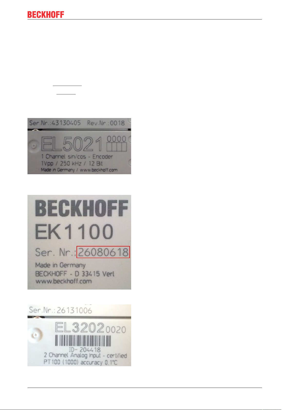
The serial number for Beckhoff IO devices is usually the 8-digit number printed on the device or on a sticker.
The serial number indicates the configuration in delivery state and therefore refers to a whole production
batch, without distinguishing the individual modules of a batch.
Structure of the serial number: KKYYFFHH
KK - week of production (CW, calendar week)
YY - year of production
FF - firmware version
HH - hardware version
EL511210 Version: 1.1
Page 11
Foreword
Example with
Ser. no.: 12063A02: 12 - production week 12 06 - production year 2006 3A - firmware version 3A 02 hardware version 02
Unique serial number/ID, ID number
In addition, in some series each individual module has its own unique serial number.
See also the further documentation in the area
• IP67: EtherCAT Box
• Safety: TwinSafe
• Terminals with factory calibration certificate and other measuring terminals
Examples of markings
Fig.1: EL5021 EL terminal, standard IP20 IO device with serial/ batch number and revision ID (since
2014/01)
Fig.2: EK1100 EtherCAT coupler, standard IP20 IO device with serial/ batch number
Fig.3: EL3202-0020 with serial/ batch number 26131006 and unique ID-number 204418
EL5112 11Version: 1.1
Page 12
Foreword
1.4.1 Beckhoff Identification Code (BIC)
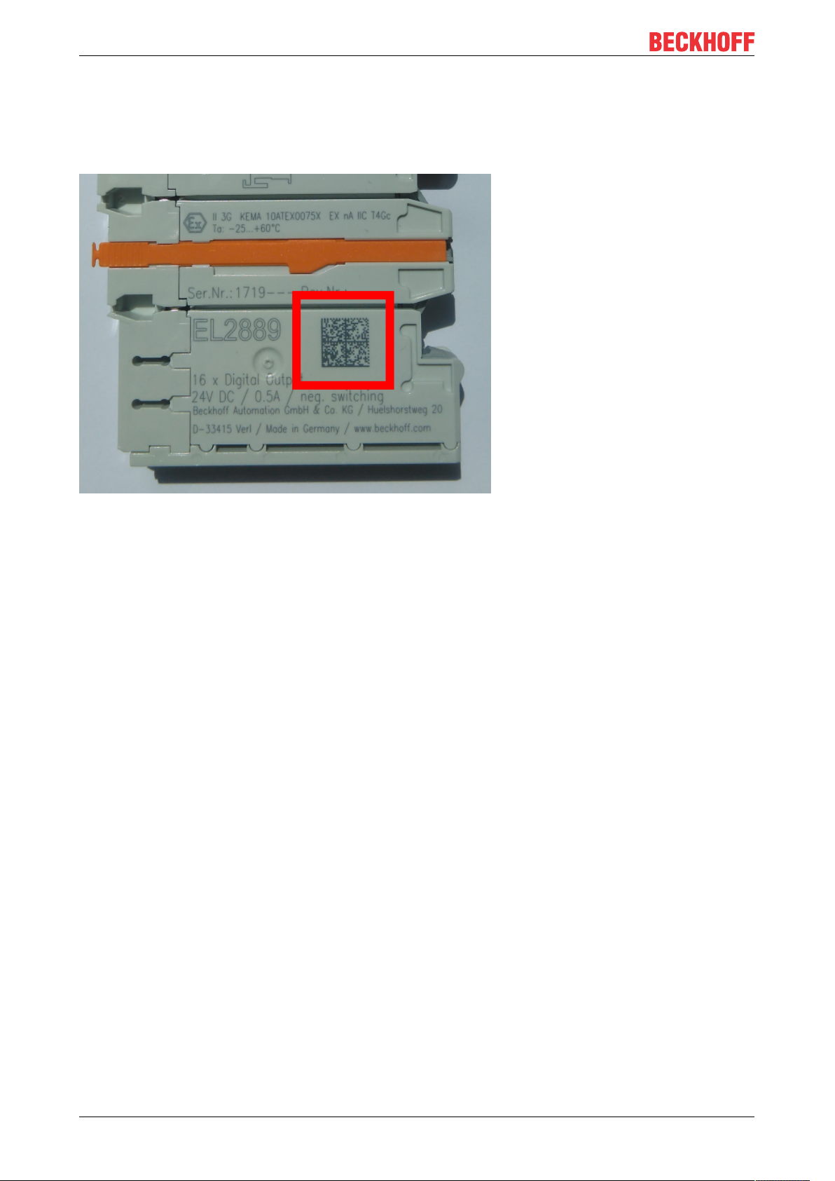
The Beckhoff Identification Code (BIC) is increasingly being applied to Beckhoff products to uniquely identify
the product. The BIC is represented as a Data Matrix Code (DMC, code scheme ECC200), the content is
based on the ANSI standard MH10.8.2-2016.
Fig.4: BIC as data matrix code (DMC, code scheme ECC200)
The BIC will be introduced step by step across all product groups.
Depending on the product, it can be found in the following places:
• on the packaging unit
• directly on the product (if space suffices)
• on the packaging unit and the product
The BIC is machine-readable and contains information that can also be used by the customer for handling
and product management.
Each piece of information can be uniquely identified using the so-called data identifier
(ANSIMH10.8.2-2016). The data identifier is followed by a character string. Both together have a maximum
length according to the table below. If the information is shorter, spaces are added to it. The data under
positions 1 to 4 are always available.
The following information is contained:
EL511212 Version: 1.1
Page 13

Item
Type of
no.
information
1 Beckhoff order
number
2 Beckhoff Traceability
Number (BTN)
3 Article description Beckhoff article
4 Quantity Quantity in packaging
5 Batch number Optional: Year and week
6 ID/serial number Optional: Present-day
7 Variant number Optional: Product variant
...
Explanation Data
Beckhoff order number 1P 8 1P072222
Unique serial number,
see note below
description, e.g.
EL1008
unit, e.g. 1, 10, etc.
of production
serial number system,
e.g. with safety products
or calibrated terminals
number on the basis of
standard products
Foreword
Number of digits
identifier
S 12 SBTNk4p562d7
1K 32 1KEL1809
Q 6 Q1
2P 14 2P401503180016
51S 12 51S678294104
30P 32 30PF971, 2*K183
incl. data identifier
Example
Further types of information and data identifiers are used by Beckhoff and serve internal processes.
Structure of the BIC
Example of composite information from item 1 to 4 and 6. The data identifiers are marked in red for better
display:
BTN
An important component of the BIC is the Beckhoff Traceability Number (BTN, item no.2). The BTN is a
unique serial number consisting of eight characters that will replace all other serial number systems at
Beckhoff in the long term (e.g. batch designations on IO components, previous serial number range for
safety products, etc.). The BTN will also be introduced step by step, so it may happen that the BTN is not yet
coded in the BIC.
NOTE
This information has been carefully prepared. However, the procedure described is constantly being further
developed. We reserve the right to revise and change procedures and documentation at any time and without prior notice. No claims for changes can be made from the information, illustrations and descriptions in
this information.
EL5112 13Version: 1.1
Page 14
Product overview
2 Product overview
2.1 EL5112 - Introduction
Two-channel incremental encoder interface terminal 5V (2xAB or 1xABC RS422, TTL)
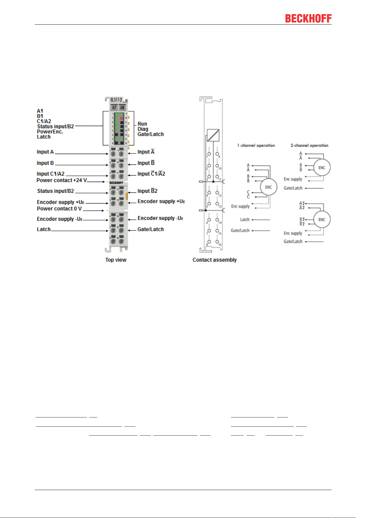
Fig.5: EL5112
The EL5112 EtherCAT Terminal is an interface for the direct connection of two incremental encoders with A
and B tracks or one encoder with A, B and C tracks. Encoders with differential signals (RS422) or singleended signals (TTL and Open Collector) can be connected and supplied with power directly from the
terminal.
In 2-channel mode, both channels of the gate can be used for locking the counter and optionally as a latch
for the separate storage of the counter value. Up to two latch inputs are available in single-channel mode.
The EL5112 enables the measurement of period, frequency and speed with a resolution of 10ns. In addition,
duty cycle measurement of the incoming signal is implemented.
Due to the optional interpolating micro-increment function, the EL5112 can supply even more precise axis
positions for dynamic axes. In addition to that it supports the synchronous reading of the encoder value
together with other input data in the EtherCAT system via high-precision EtherCAT Distributed Clocks (DC).
In addition, timestamps can be output for the last registered incremental edge, the edge at the latch input
and the zero pulse track C.
Quick links
Basics communication [}25]
Creation of the TwinCAT configuration [}105]
EL5112 - Process data (single-channel mode [}136], two-channel mode [}182])
Configuration data [}227]
EL5112 - Object description [}226]
LEDs [}61] and connection [}47]
EL511214 Version: 1.1
Page 15

Product overview
2.2 EL5112 - Technical data
Technical data EL5112
Single-channel mode Two-channel mode
Encoder type Incremental, differential (RS422), single-ended (TTL, open collector), counter, pulse gen-
Encoder connection Differential inputs (RS422): A, A, B, B, C, C
Number of channels 1 x A, B, C 2 x A, B
Additional inputs Latch, Gate/Latch (24VDC, t
Encoder operating voltage 5V
Counter 32bit (default) or 16bit switchable
Cut-off frequency RS422 mode: 20million increments with 4-fold evaluation, corresponds to 5MHz
Quadrature decoder 4-fold evaluation (preset), 2-fold, 1-fold evaluation switchable
Micro-increments resolution 1/256bit micro-increments no
Broken wire detection to encoder yes for RS422 encoder
Distributed Clocks yes
Timestamp Resolution 1ns no
Special functions Period duration, frequency and speed mea-
Cycle time min. 100µs
Current consumption via E-bus typ. 190mA
Current consumption from power contacts typ.10mA+load
Electrical isolation 500V (E-bus/field voltage)
Configuration
Weight approx.50g
Permissible ambient temperature range
during operation
Permissible ambient temperature range
during storage
Permissible relative air humidity 95%, no condensation
Dimensions (W x H x D) approx. 15mm x100mm x 70mm (width aligned: 12mm)
Assembly [}35]
Vibration/shock resistance conforms to EN60068-2-6 / EN60068-2-27,
EMC immunity/emission conforms to EN61000-6-2/ EN61000-6-4
Protection class IP20
Installation position variable
Approval CE
erator
Differential inputs (RS422): A, A, B, B
Single-ended connection (TTL, Open Collector): A, B, C
Single-ended connection (TTL, Open Collector): A, B
Counters, pulse generators: A, B
>1µs),
ON
Gate/Latch (24VDC, t
>1µs) per channel
ON
Status Input input (max. 5VDC, negative
switching, t
DC
power contacts)
>10µs)
ON
(preset), 12VDC, 24V
switchable, 0.3A sum current (generated from the 24VDC-
DC
TTL mode: 4million increments with 4-fold evaluation, corresponds to 1MHz
Open Collector: 400,000 increments with 4-fold evaluation, corresponds to 100kHz
Period duration, frequency and speed mea-
surement,
surement
Duty Cycle measurement, micro-increments,
filters,
Timestamp on: last incremental edge, zero
pulse C, Latch input and Gate/Latch input
via TwinCAT System Manager [}113]
0°C ... +55°C
-25°C ... +85 °C
on 35mm support rail according to EN60715
see also Installation instructions [}39] for enhanced mechanical load capacity
EL5112 15Version: 1.1
Page 16

Product overview
2.3 Overview of functions in single-channel and twochannel mode
Function
Set counter value via PLC variable X X
zero pulse C X /
Latch input X /
Gate/Latch
combination input
Reset counter value via zero pulse C X /
Latch input X /
Gate/Latch
combination input
Save counter value via zero pulse C X /
Latch input X /
Gate/Latch input X /
Gate/Latch
combination input
Lock counter value via PLC variable X X
Gate/Latch input X /
Gate/Latch
combination input
Detect counting direction X /
Detect reversion of rotation X /
Frequency calculation X X
Period duration calculation X X
Duty cycle evaluation X /
Micro-increments X /
Timestamp function X /
Filter function X X
Plausibility check X X
Single-channel mode 1
x ABC [}134]
/ X
/ X
/ X
/ X
Two-channel mode 2 x AB
[}181]
2.4 Start
For commissioning:
• mount the EL5112 as described in the chapter Mounting and wiring [}35]
• configure the EL5112 in TwinCAT as described in the chapter Commissioning [}63].
• Parameterize the EL5112 as described in chapters EL5112 - Commissioning in single-channel mode
[}134] and EL5112 - Commissioning in two-channel mode [}181].
EL511216 Version: 1.1
Page 17

2.5 EL51xx series overview
Product overview
Technical data EL5102
2 x A, B, C
Number of channels 2 1 2 2 1
Encoder
type,
incremental
Number of digital inputs per
channel
Number of digital outputs per
channel
Encoder operating voltage
switchable between 5VDC,
12VDC, 24V
Encoder output current per
channel
Cut-off frequency 20 million in-
Differential RS422 X X X / X
Single-ended TTL X X X X X
OpenCollector X X X X X
Counter / pulse
generator
DC
X X X X X
2 2 1 1 2
/ / / / 2
X X X X X
0.3 A 0.3 A Sum current
crements,
correspond-
ing to 5 MHz
1 x A, B, C 2 x A, B
20 million in-
crements,
correspond-
ing to 5 MHz
EL5112 EL5122
2 x A, B
Sum current
0.3 A
20 million in-
crements,
correspond-
ing to 5 MHz
0.3 A
4 million in-
crements,
correspond-
ing to 1 MHz
EL5131
1 x A, B, C
0.3 A
20 million in-
crements,
correspond-
ing to 5 MHz
Functions EL5102
2 x A, B, C
Reset
counter
value via
Set counter
value via
Save
counter
value via
Lock counter
value via
Switching at comparison values
(Counter / Frequency / Period
value)
Detect counting direction X X / / X
Detect reversion of rotation X X / / X
Frequency measurement X X X X X
Period value measurement X X X X X
Velocity, speed calculation X X X X X
Duty cycle evaluation X X / / X
Micro-increments X X / / X
Timestamp function X X / / X
Adjustable interference pulse
filters
Plausibility check X X X X X
zero pulse C X X / / X
Latch input X X X X X
PLC variable X X X X X
zero pulse C X X / / X
Latch input X X X / X
Gate/Latch input / / X X /
zero pulse C X X / / X
Latch input X X X / X
Gate/Latch input X X / X X
PLC variable X X X X X
Gate/Latch input X X X X X
/ / / / X
X X X X X
1 x A, B, C 2 x A, B
EL5112 EL5122
2 x A, B
EL5131
1 x A, B, C
EL5112 17Version: 1.1
Page 18
Product overview
2.6 Technology
The incremental encoder interface terminals of the EL51xx series enable the connection of incremental
encoders to Bus Couplers or the PLC.
Incremental encoder basics
Incremental encoders divide a 360° rotation of the encoder axis into individual steps (increments) and mark a
full revolution by means of a special mark (zero pulse). An RS422 encoder transmits the signal symmetrically
as a differential line pair. TTL and Open Collector encoders use single signal lines (single-ended).
The terminal evaluates the 90° phase-shifted square wave signals of an incremental encoder on tracks A
and B. The zero pulse is captured on track C. With a differential connection, the inverted signals (A, B, C)
are also recorded.
These signals are converted by means of the quadrature decoder and the 32-bit counter into a position value
with optional quadruple, double or single evaluation. The digital inputs enable latch, reset and set
functionalities and thus exact and speed-independent referencing and storage of the counter value.
Encoder type Incremental signals
RS422 encoder with zero pulse A, A, B, B, C, C
RS422 encoder without zero pulse A, A, B, B
RS422 counter or pulse generator with zero pulse A, A, C, C;
Counting direction specification via track B (B, B)
RS422 counter or pulse generator without zero pulse A, A;
Counting direction specification via track B (B, B)
TTL, Open Collector encoder with zero pulse A, B, C
TTL, Open Collector encoder without zero pulse A, B
TTL, Open Collector counter or pulse generator with zero pulse A, C;
Counting direction specification via B
TTL, Open Collector counter or pulse generator without zero pulse A,
Counting direction specification via B
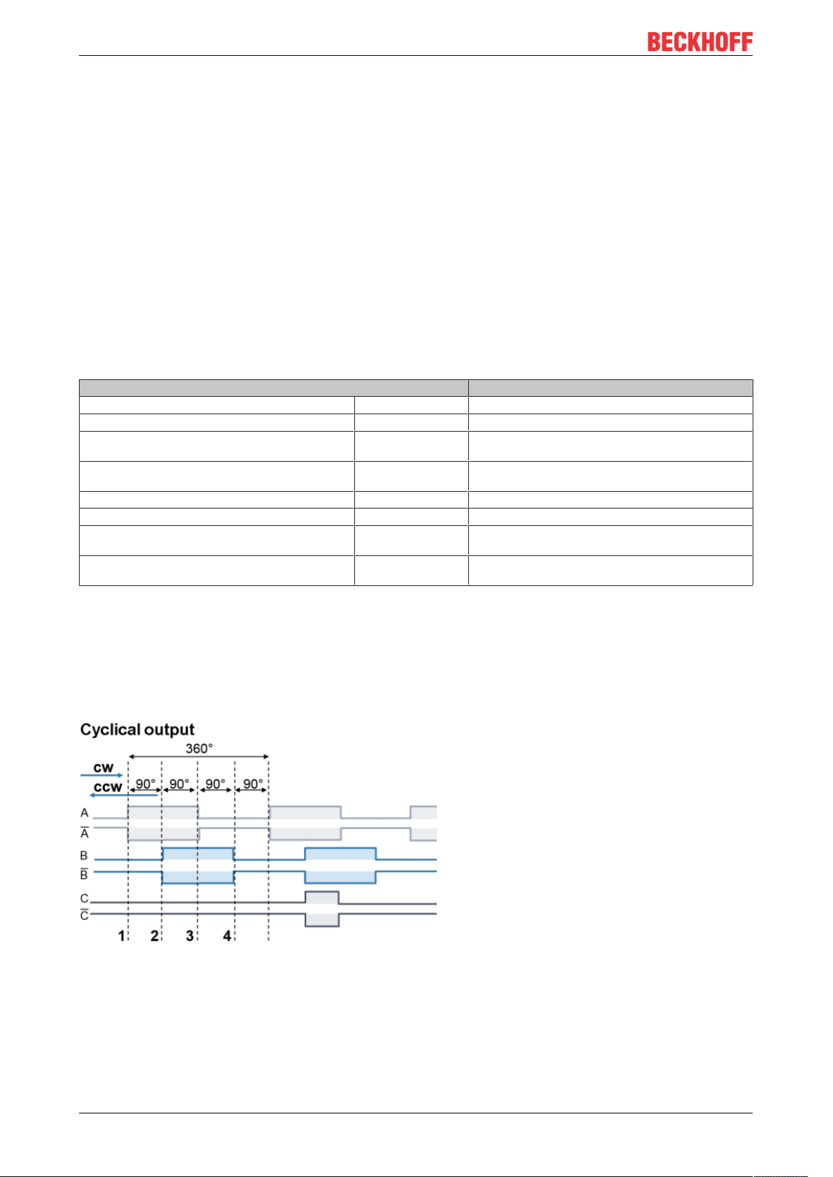
The phase position between the signals on track A and track B determines the counting direction.
Forward (cw): Signal on track A leads track B by 90°
Reverse (ccw): Signal on track A lags track B by 90°.
With single evaluation the rising edges on track A are counted.
With double evaluation the rising and falling edges on track A are counted.
With quadruple evaluation the rising and falling edges on track A and track B are counted.
Fig.6: Incremental signals
Absolute value encoders provide an absolute position value directly after switch-on, which is unambiguous
over the entire travel path. With incremental encoders, homing must be performed after switch-on in order to
be able to determine an unambiguous position.
Referencing can be carried out, for example, with the aid of referencing cams or using the zero pulse of the
encoder.
EL511218 Version: 1.1
Page 19

Product overview
NOTE
Differential and single-ended connection
• The RS422 signal transmits a differential voltage, which makes the signal less sensitive to interference
compared to a single-ended signal.
ð If the encoder signal is to be transmitted over longer distances or at higher frequencies, an encoder
with RS422 signals is recommended.
ð Shielded and twisted pair cables should be used.
2.7 Technical properties
The EL51xx series incremental encoder interface terminals enable connection of incremental encoders. In
addition to the encoder inputs A, B and optional zero pulse C, up to two additional 24VDC inputs are available
(latch and gate/latch), which can be used for resetting, setting, blocking and storing the counter value. If the
incremental encoder has a fault signal output, this can be connected to the Status Input input (5VDC).
The following inputs are available with the respective technical characteristics:
• Encoder connection: differential signals according to RS422 and single-ended signals from TTL
encoders and Open Collector encoders are supported.
• Latch input and Gate/Latch input
• Status Input
The terminal also provides a parameterizable encoder supply.
• Encoder operating voltage
NOTE
Fast digital inputs – interference from interfering devices
Please note that the input wiring has very little filtering. It has been optimized for fast signal transmission
from the input to the evaluation unit. In other words, rapid level changes/pulses in the µs range and/or highfrequency interference signals from devices (e.g. proportional valves, stepper motor or DC motor output
stages) arrive at the evaluation unit almost unfiltered/unattenuated. These interferences can be incorrectly
detected as a signal.
To suppress interference, an additional input filter can be parameterized. Furthermore, EMC-compliant cabling and the use of separate power supply units for the terminal and the devices causing interference are
recommended.
2.7.1 Signal types
Supported encoders / signal types
Differential signals according to RS422 are provided as encoder connection. Single-ended signals from TTL
encoders and also signals from Open Collector encoders are possible through internal pull-up resistors.
The following signal types are supported:
EL5112 19Version: 1.1
Page 20
Product overview
Encoder Signal type Setting in
Encoder
with or without zero pulse track C
Counter/pulse generator
with or without zero pulse track C
Encoder
with or without zero pulse track C
Counter/pulse generator
with or without zero pulse track C
Encoder
with or without zero pulse track C
Counter/pulse generator
with or without zero pulse track C
RS422
(diff. input)
TTL
(single ended)
open collector 4 400,000 increments
index 0x80n1:1D
"Counter mode"
0 20 million increments
1
2 4 million increments
3
5
Cut-off frequency Comments
with 4-fold evaluation,
corresponds to 5MHz per
track
with 4-fold evaluation,
corresponds to 1MHz per
track
with 4-fold evaluation,
corresponds to 100kHz per
track
Signal levels according to
RS422 are expected
Detection of
broken wire and short circuit
A voltage level of nominally
2.0V to 6.0V with a current
of 2.1mA or higher is expected.
No broken wire detection
No broken wire detection
The correct wiring for the respective encoder can be found in chapter Connection.
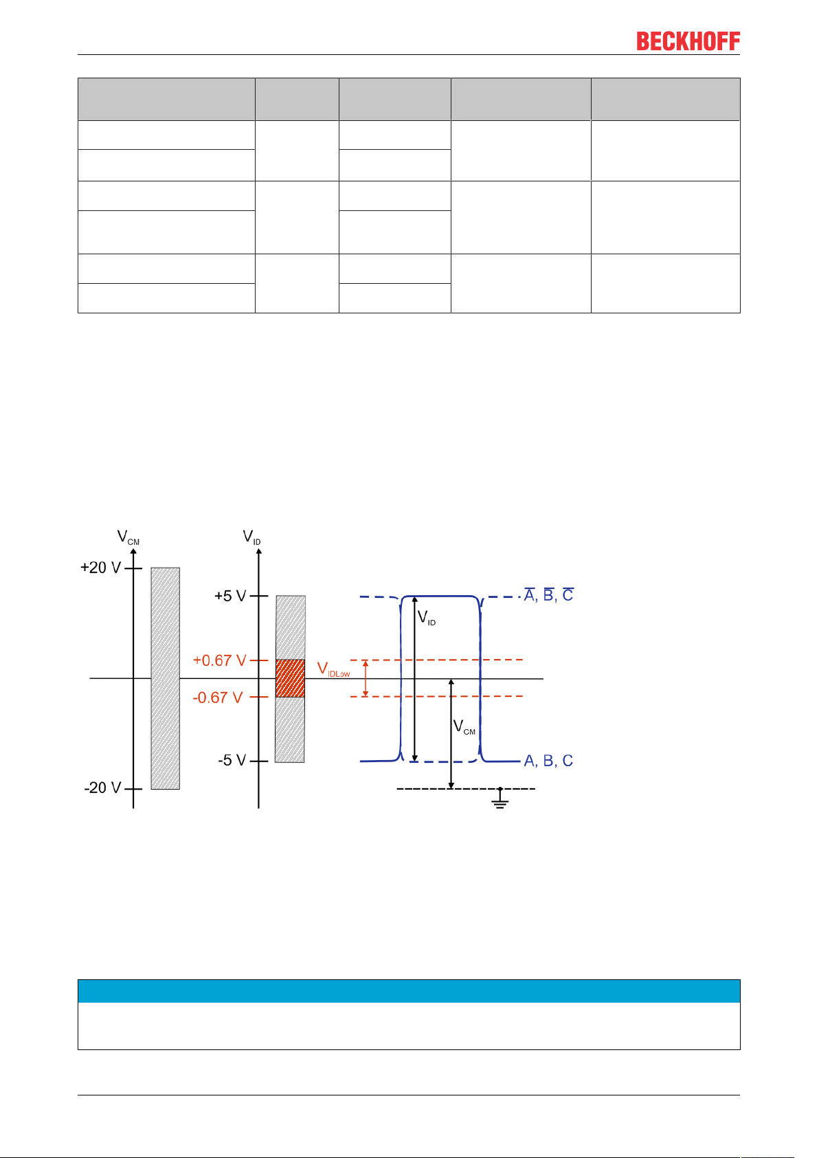
Signal type RS422 (diff. input)
The terminal expects the differential signal levels according to RS422 with the following settings in "Counter
mode" (0x80n1:1D):
• 0: Encoder RS422 (diff. input)
• 1: Counter RS422 (diff. input)
A cut-off frequency of up to 20million increments per second is permissible with 4-fold evaluation. This
corresponds to 5MHz.
Fig.7: RS422 signal level
Key:
V
CM
V
ID
V
IDLow
A, B, C Signals A, B, C
A, B, C
Common mode voltage range
Differential voltage
Differential voltage too low
Inverted signals A, B, C
NOTE
Exceeding of Common Mode range
Exceeding the Common Mode voltage range can lead to destruction of the device.
EL511220 Version: 1.1
Page 21

Product overview
RS422 - broken wire and short-circuit detection (open circuit)
In the RS422 (differential input) modes it is possible to detect a broken wire or short circuit at the individual
encoder inputs.
• In case of a broken wire, e.g. between input A and input A,
◦ the differential voltage VID is almost 0V,
◦ which leads to an error with low differential voltage.
• In case of a short circuit, e.g. between input A and input A, the error behavior is similar to a broken wire
and also leads to error detection.
Activation of error detection for each channel
Index (hex) Name Description
80n0:0B Error detection A TRUE Broken wire and short circuit detection for encoder input A enabled
FALSE Broken wire and short circuit detection for encoder input A disabled
80n0:0C Error detection B TRUE Broken wire and short circuit detection for encoder input B enabled
FALSE Broken wire and short circuit detection for encoder input B disabled
80n0:0D Error detection C TRUE Broken wire and short circuit detection for encoder input C enabled
FALSE Broken wire and short circuit detection for encoder input C disabled
Error detection using the example of a broken wire or short circuit between inputs A and A.
Error diagnosis Display Description
LED A1 Green A TRUE level is present
Red An error (open circuit) was detected
0x60n07 "Open circuit" TRUE Group error message for "Open circuit"
FALSE There is no "open circuit" error.
0xA0n0:01 "Error A" TRUE An "open circuit" error (broken wire or short circuit) has occurred at encoder input A.
FALSE There is no "open circuit" error.
A broken wire or short circuit has occurred at one of the encoder inputs
NOTE
Differential and single-ended connection
• The RS422 signal transmits a differential voltage, which makes the signal less sensitive to interference
compared to a single-ended signal.
ð If the encoder signal is to be transmitted over longer distances or at higher frequencies, an encoder
with RS422 signals is recommended.
ð Shielded and twisted pair cables should be used.
EL5112 21Version: 1.1
Page 22
Product overview
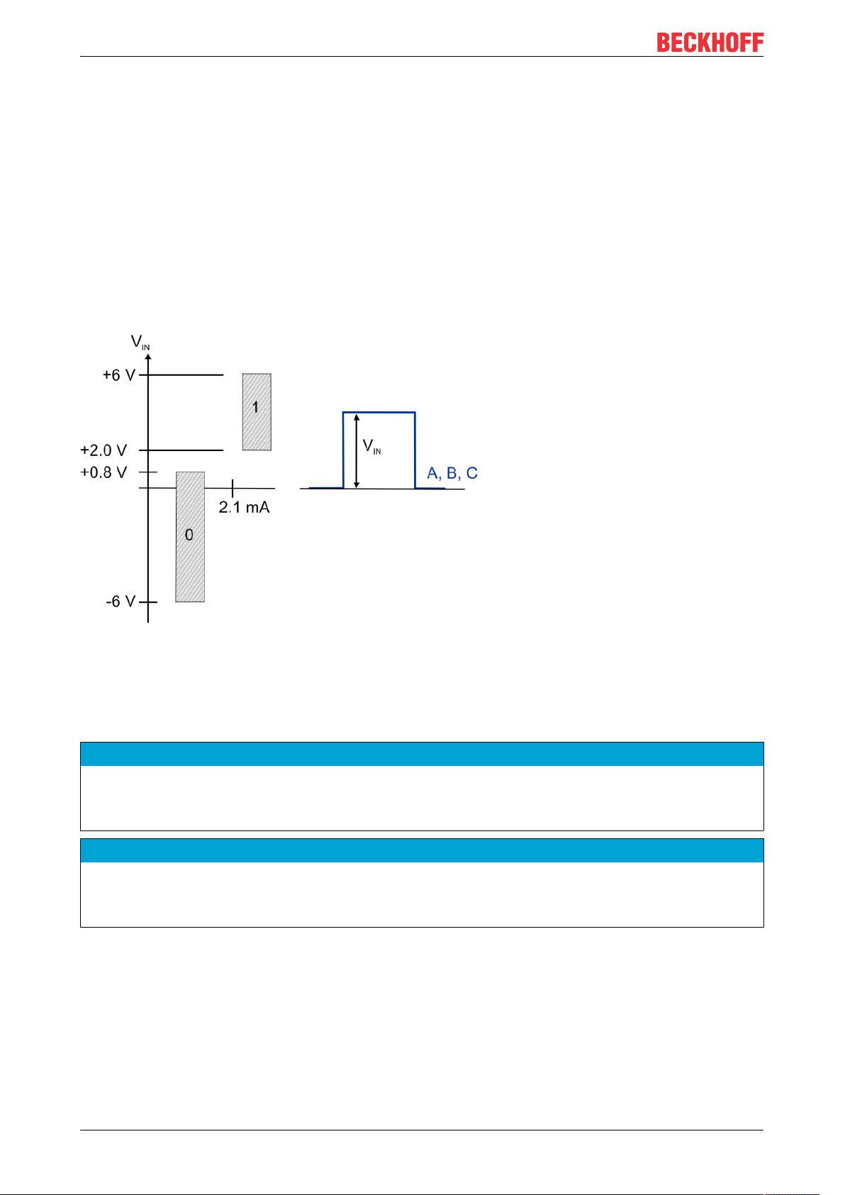
Signal type TTL (single-ended) and Open Collector
With the following settings in "Counter mode" (0x80n1:1D), a voltage level of nominally 2.0V to 6.0V with a
current of 2.1mA or higher is expected:
• 2: Encoder TTL (single-ended)
• 3: Counter TTL (single-ended)
• 4: Encoder open collector
• 5: Counter open collector
For TTL encoders a cut-off frequency of up to 4 million increments per second is permissible with 4-fold
evaluation. This corresponds to 1MHz.
For Open Collector encoders, a cut-off frequency of up to 400,000 increments per second is permissible with
4-fold evaluation. This corresponds to 100kHz.
Fig.8: TTL, Open Collector signal level (single-ended signal)
Key:
V
IN
A, B, C Encoder signals A, B, C
Single-ended input voltage
NOTE
Open circuit detection
Open circuit detection inherently does not work with single-ended lines: TTL and Open Collector encoders
and counters/pulse generators.
NOTE
Open Collector wiring
When selecting an Open Collector encoder under "Counter mode" (0x80n1:1D), the inputs A, B, C are connected to 5V via pull-up resistors (1kΩ).
EL511222 Version: 1.1
Page 23
Product overview
2.7.2 Latch and Gate/Latch inputs
The terminal provides two digital 24VDC inputs. The function of these inputs is described in the respective
chapter.
• Latch input [}177] (Latch extern)
• Gate/latch input [}178] (Latch extern 2)
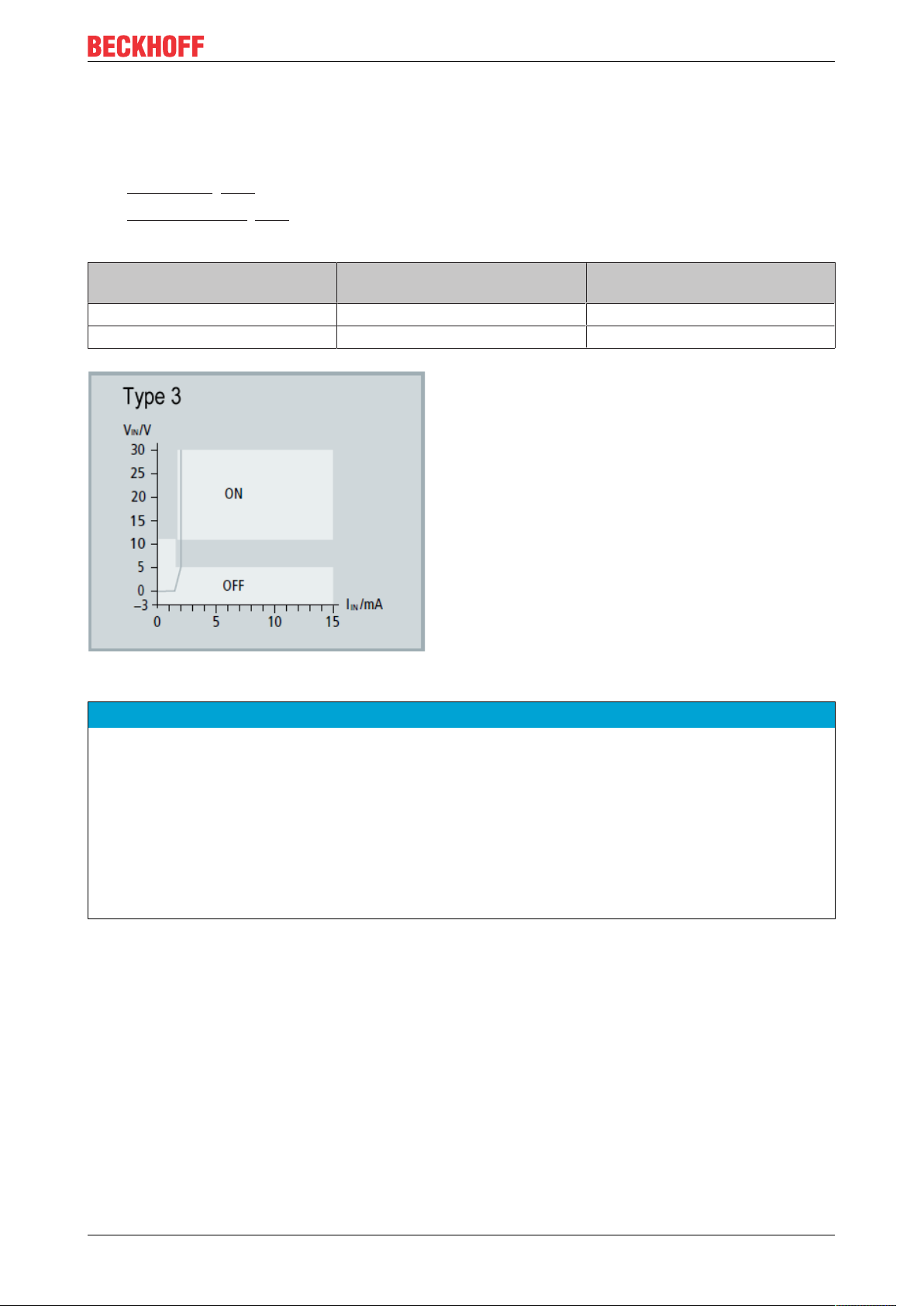
Both inputs are type 3 inputs according to EN61131-2, with a minimum pulse duration of tON>1µs.
Digital input type 3, according to
EN61131-2
Signal voltage "0 - LOW" -3V ... +5V typ. 0mA ... 2.6mA typ.
Signal voltage "1 - HIGH" 11V ... 30V typ. typ. 2.5mA
Fig.9: Characteristic 24VDC Input type 3
Voltage [V] Input current [mA]
NOTE
Be aware of bouncing when using electromechanical switches and push buttons
When using electromechanical switches and push buttons, repeated closing and opening of the switch or
push button can occur when the switch or push button is actuated, which is referred to as bouncing.
• If the function 0x80n0:22 "Enable continuous latch extern" or 0x80n0:23 "Enable continuous latch extern
2" is active, the stored value is overwritten several times due to the bouncing. As a result, parameter
0x60n0: 12 "Latch value" or 0x60n0: 22 "Latch value 2" contains the value that was saved last, not the
value that was saved first.
• If the function is deactivated, only the first opening or closing of the switch or push button is detected and
saved as a value in the corresponding parameter. No other transactions are taken into account.
EL5112 23Version: 1.1
Page 24

Product overview
2.7.3 Status Input
The terminal provides a Status Input. The function is described in chapter Status Input. [}180]
The input is 5V compatible.
Digital input,
5V TTL input characteristic
Signal voltage "0 - LOW" -6V … + 0.8V typ. 5mA
Signal voltage "1 - HIGH" +2V … +6V typ. 0mA
Voltage [V] Input current [mA]
NOTE
Wiring of the Status Input
In the terminal the Status Input is internally connected to 5V via a pull-up resistor (1kΩ). The encoder output must actively pull the signal against GND. The resistance must be dimensioned so that it is less than
120Ω.
External power supply is not recommended. If an external supply is used, the maximum permitted voltage
is 5V against GND.
2.7.4 EL5112 - Encoder operating voltage (supply voltage)
The encoder supply is generated internally from the 24V of the power contacts. The encoder supply can be
set in index 0x8001 [}228]:17 "Supply voltage". An operating voltage of 5VDC is preset. Voltage values of
5VDC, 12VDC and 24VDC can be selected. The setting applies to both channels. Before switching to higher
voltages, ensure that both encoders support the voltage range.
The following tolerances apply
Voltage range Tolerance
5V
12V
24V
DC
DC
DC
+/- 5% (4.75V … 5.25V)
+/- 10% (10.8V … 13.2V)
-15% to +20% (20.4V … 28.8V)
Setting the encoder supply via index 0x8001:17 [}228]
The encoder supply is set centrally for both terminal channels via the index 0x8001:17 [}228] (channel 1). The corresponding index 0x8011:17 of the second channel has no parameterization function.
NOTE
Setting the encoder supply voltage
• Before switching to a higher voltage, make sure that the connected encoders support the selected voltage range!
• To write to 0x80n1:17 "Supply voltage" you have to set the value 0x72657375 (ASCII: "user") in index
0xF008 [}256] "Code word".
EL511224 Version: 1.1
Page 25

Basics communication
3 Basics communication
3.1 EtherCAT basics
Please refer to the EtherCAT System Documentation for the EtherCAT fieldbus basics.
3.2 EtherCAT cabling – wire-bound
The cable length between two EtherCAT devices must not exceed 100 m. This results from the FastEthernet
technology, which, above all for reasons of signal attenuation over the length of the cable, allows a maximum
link length of 5 + 90 + 5 m if cables with appropriate properties are used. See also the Design
recommendations for the infrastructure for EtherCAT/Ethernet.
Cables and connectors
For connecting EtherCAT devices only Ethernet connections (cables + plugs) that meet the requirements of
at least category 5 (CAt5) according to EN 50173 or ISO/IEC 11801 should be used. EtherCAT uses 4 wires
for signal transfer.
EtherCAT uses RJ45 plug connectors, for example. The pin assignment is compatible with the Ethernet
standard (ISO/IEC 8802-3).
Pin Color of conductor Signal Description
1 yellow TD + Transmission Data +
2 orange TD - Transmission Data 3 white RD + Receiver Data +
6 blue RD - Receiver Data -
Due to automatic cable detection (auto-crossing) symmetric (1:1) or cross-over cables can be used between
EtherCAT devices from Beckhoff.
Recommended cables
It is recommended to use the appropriate Beckhoff components e.g.
- cable sets ZK1090-9191-xxxx respectively
- RJ45 connector, field assembly ZS1090-0005
- EtherCAT cable, field assembly ZB9010, ZB9020
Suitable cables for the connection of EtherCAT devices can be found on the Beckhoff website!
E-Bus supply
A bus coupler can supply the EL terminals added to it with the E-bus system voltage of 5V; a coupler is
thereby loadable up to 2A as a rule (see details in respective device documentation).
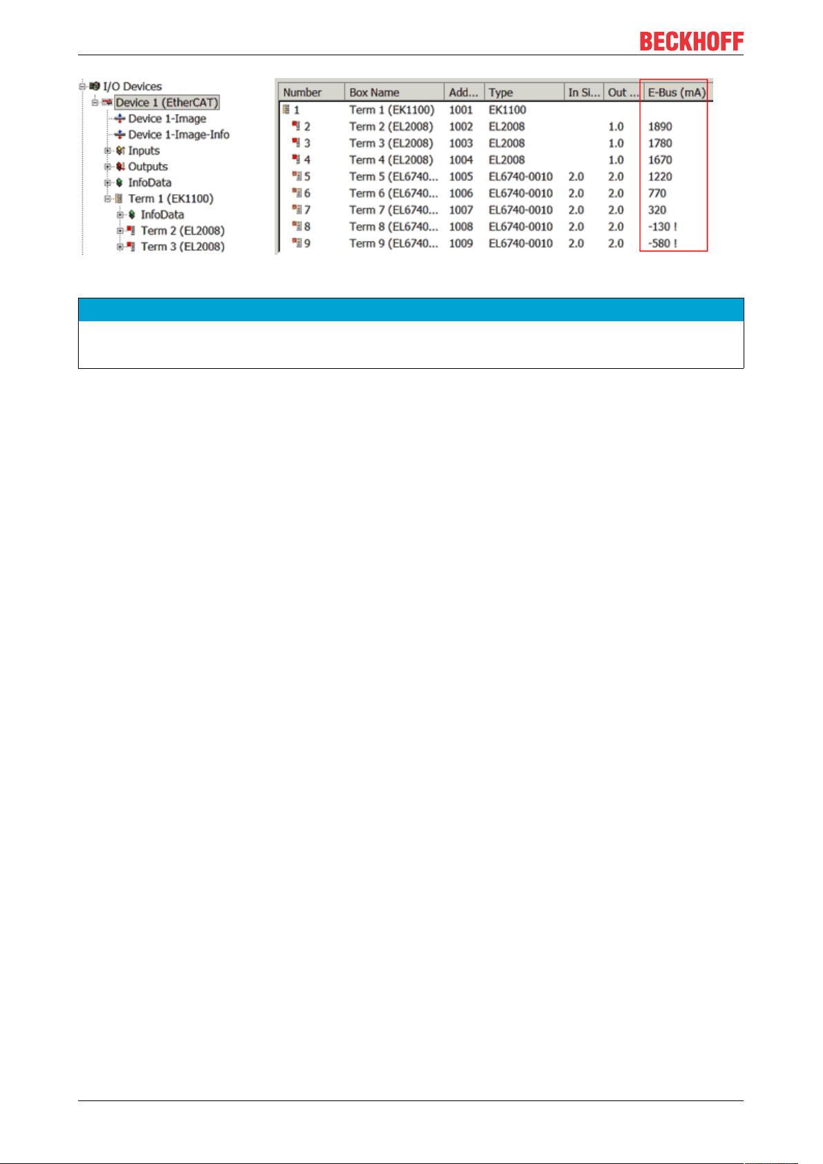
Information on how much current each EL terminal requires from the E-bus supply is available online and in
the catalogue. If the added terminals require more current than the coupler can supply, then power feed
terminals (e.g. EL9410) must be inserted at appropriate places in the terminal strand.
The pre-calculated theoretical maximum E-Bus current is displayed in the TwinCAT System Manager. A
shortfall is marked by a negative total amount and an exclamation mark; a power feed terminal is to be
placed before such a position.
EL5112 25Version: 1.1
Page 26
Basics communication
Fig.10: System manager current calculation
NOTE
Malfunction possible!
The same ground potential must be used for the E-Bus supply of all EtherCAT terminals in a terminal block!
3.3 General notes for setting the watchdog
ELxxxx terminals are equipped with a safety feature (watchdog) that switches off the outputs after a
specifiable time e.g. in the event of an interruption of the process data traffic, depending on the device and
settings, e.g. in OFF state.
The EtherCAT slave controller (ESC) in the EL2xxx terminals features two watchdogs:
• SM watchdog (default: 100 ms)
• PDI watchdog (default: 100 ms)
SM watchdog (SyncManager Watchdog)
The SyncManager watchdog is reset after each successful EtherCAT process data communication with the
terminal. If no EtherCAT process data communication takes place with the terminal for longer than the set
and activated SM watchdog time, e.g. in the event of a line interruption, the watchdog is triggered and the
outputs are set to FALSE. The OP state of the terminal is unaffected. The watchdog is only reset after a
successful EtherCAT process data access. Set the monitoring time as described below.
The SyncManager watchdog monitors correct and timely process data communication with the ESC from the
EtherCAT side.
PDI watchdog (Process Data Watchdog)
If no PDI communication with the EtherCAT slave controller (ESC) takes place for longer than the set and
activated PDI watchdog time, this watchdog is triggered.
PDI (Process Data Interface) is the internal interface between the ESC and local processors in the EtherCAT
slave, for example. The PDI watchdog can be used to monitor this communication for failure.
The PDI watchdog monitors correct and timely process data communication with the ESC from the
application side.
The settings of the SM- and PDI-watchdog must be done for each slave separately in the TwinCAT System
Manager.
EL511226 Version: 1.1
Page 27
Basics communication
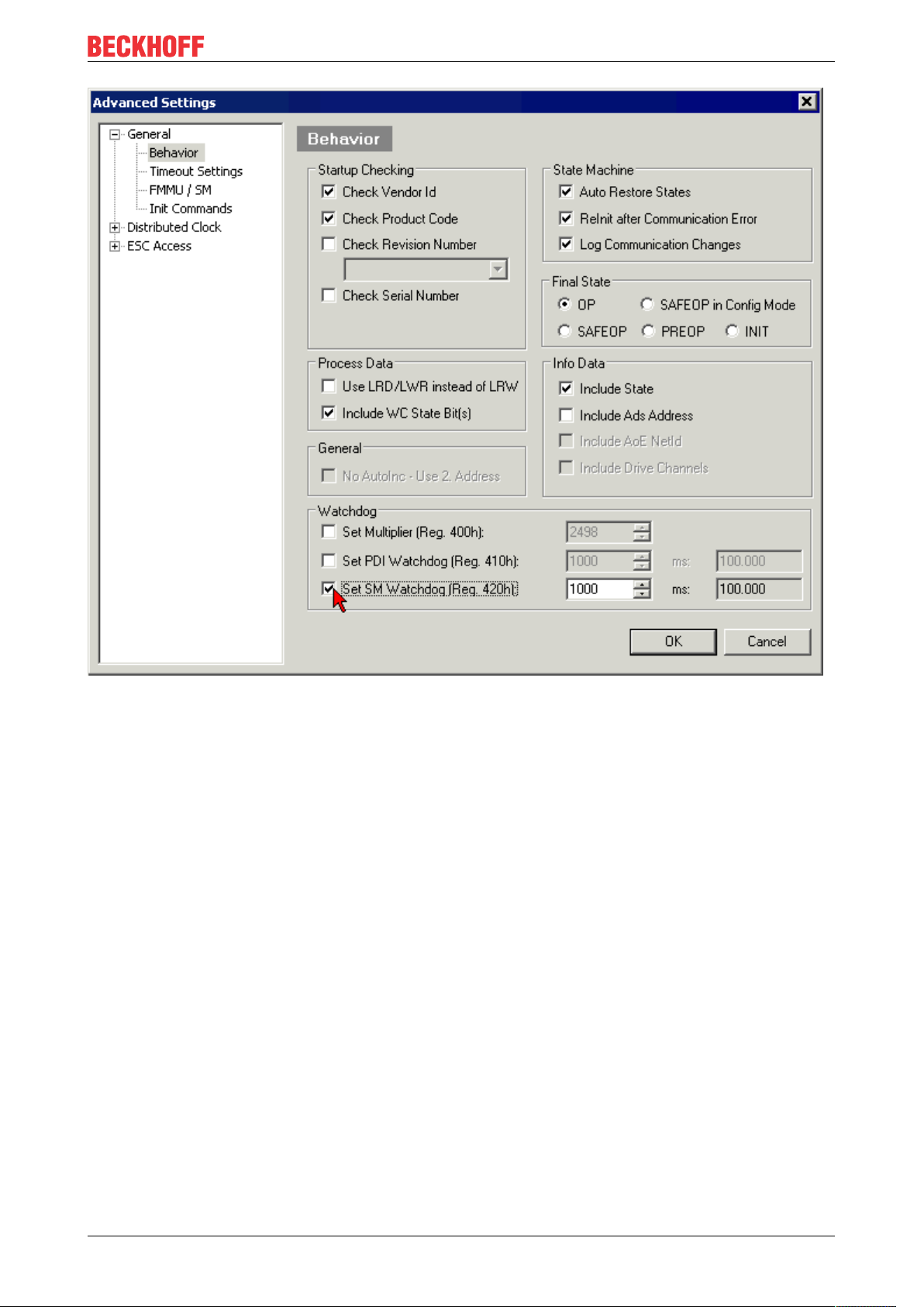
Fig.11: EtherCAT tab -> Advanced Settings -> Behavior -> Watchdog
Notes:
• the multiplier is valid for both watchdogs.
• each watchdog has its own timer setting, the outcome of this in summary with the multiplier is a
resulting time.
• Important: the multiplier/timer setting is only loaded into the slave at the start up, if the checkbox is
activated.
If the checkbox is not activated, nothing is downloaded and the ESC settings remain unchanged.
Multiplier
Both watchdogs receive their pulses from the local terminal cycle, divided by the watchdog multiplier:
1/25 MHz * (watchdog multiplier + 2) = 100µs (for default setting of 2498 for the multiplier)
The standard setting of 1000 for the SM watchdog corresponds to a release time of 100ms.
The value in multiplier + 2 corresponds to the number of basic 40 ns ticks representing a watchdog tick.
The multiplier can be modified in order to adjust the watchdog time over a larger range.
Example “Set SM watchdog”
This checkbox enables manual setting of the watchdog times. If the outputs are set and the EtherCAT
communication is interrupted, the SM watchdog is triggered after the set time and the outputs are erased.
This setting can be used for adapting a terminal to a slower EtherCAT master or long cycle times. The
default SM watchdog setting is 100ms. The setting range is 0...65535. Together with a multiplier with a
range of 1...65535 this covers a watchdog period between 0...~170 seconds.
EL5112 27Version: 1.1
Page 28
Basics communication
Calculation
Multiplier = 2498 → watchdog base time = 1 / 25MHz * (2498 + 2) = 0.0001seconds = 100µs
SM watchdog = 10000 → 10000 * 100µs = 1second watchdog monitoring time
CAUTION
Undefined state possible!
The function for switching off of the SM watchdog via SM watchdog = 0 is only implemented in terminals
from version -0016. In previous versions this operating mode should not be used.
CAUTION
Damage of devices and undefined state possible!
If the SM watchdog is activated and a value of 0 is entered the watchdog switches off completely. This is
the deactivation of the watchdog! Set outputs are NOT set in a safe state, if the communication is interrupted.
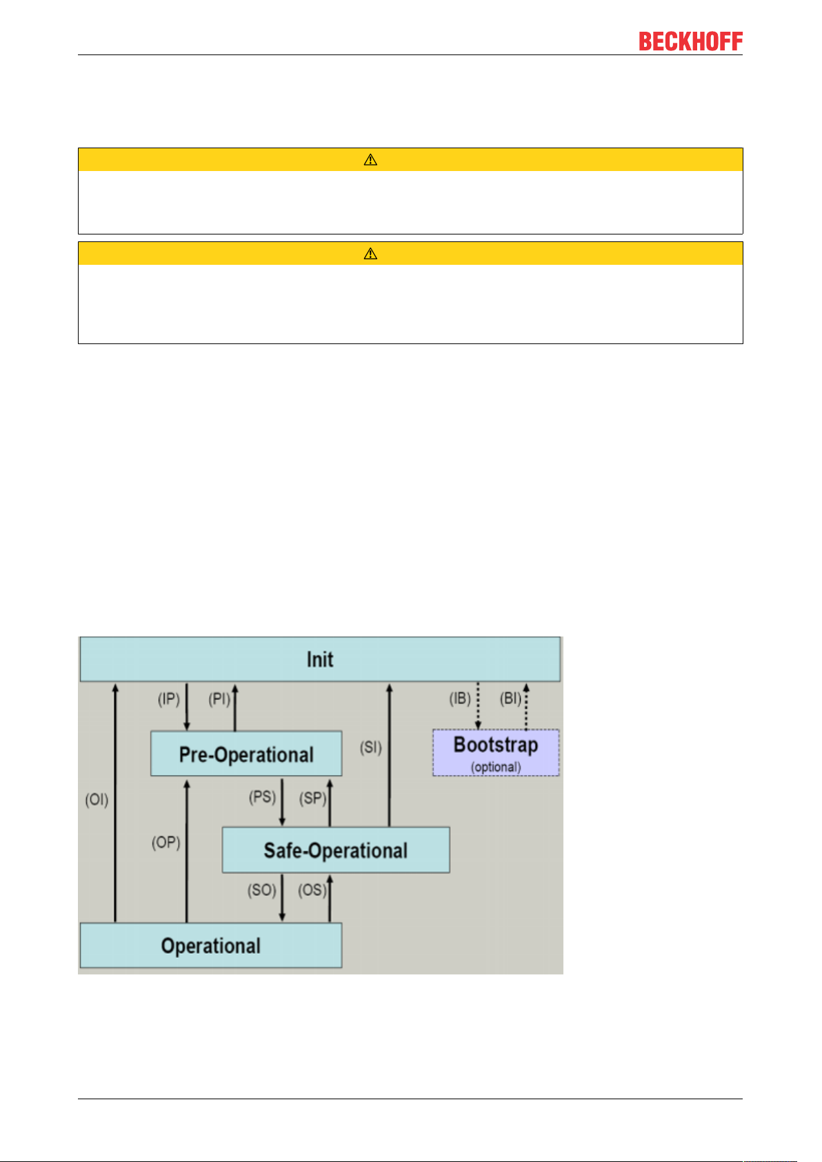
3.4 EtherCAT State Machine
The state of the EtherCAT slave is controlled via the EtherCAT State Machine (ESM). Depending upon the
state, different functions are accessible or executable in the EtherCAT slave. Specific commands must be
sent by the EtherCAT master to the device in each state, particularly during the bootup of the slave.
A distinction is made between the following states:
• Init
• Pre-Operational
• Safe-Operational and
• Operational
• Boot
The regular state of each EtherCAT slave after bootup is the OP state.
Fig.12: States of the EtherCAT State Machine
EL511228 Version: 1.1
Page 29

Basics communication
Init
After switch-on the EtherCAT slave in the Init state. No mailbox or process data communication is possible.
The EtherCAT master initializes sync manager channels 0 and 1 for mailbox communication.
Pre-Operational (Pre-Op)
During the transition between Init and Pre-Op the EtherCAT slave checks whether the mailbox was initialized
correctly.
In Pre-Op state mailbox communication is possible, but not process data communication. The EtherCAT
master initializes the sync manager channels for process data (from sync manager channel 2), the FMMU
channels and, if the slave supports configurable mapping, PDO mapping or the sync manager PDO
assignment. In this state the settings for the process data transfer and perhaps terminal-specific parameters
that may differ from the default settings are also transferred.
Safe-Operational (Safe-Op)
During transition between Pre-Op and Safe-Op the EtherCAT slave checks whether the sync manager
channels for process data communication and, if required, the distributed clocks settings are correct. Before
it acknowledges the change of state, the EtherCAT slave copies current input data into the associated DPRAM areas of the EtherCAT slave controller (ECSC).
In Safe-Op state mailbox and process data communication is possible, although the slave keeps its outputs
in a safe state, while the input data are updated cyclically.
Outputs in SAFEOP state
The default set watchdog [}26] monitoring sets the outputs of the module in a safe state - depending on the settings in SAFEOP and OP - e.g. in OFF state. If this is prevented by deactivation of the
watchdog monitoring in the module, the outputs can be switched or set also in the SAFEOP state.
Operational (Op)
Before the EtherCAT master switches the EtherCAT slave from Safe-Op to Op it must transfer valid output
data.
In the Op state the slave copies the output data of the masters to its outputs. Process data and mailbox
communication is possible.
Boot
In the Boot state the slave firmware can be updated. The Boot state can only be reached via the Init state.
In the Boot state mailbox communication via the file access over EtherCAT (FoE) protocol is possible, but no
other mailbox communication and no process data communication.
3.5 CoE Interface
General description
The CoE interface (CAN application protocol over EtherCAT)) is used for parameter management of
EtherCAT devices. EtherCAT slaves or the EtherCAT master manage fixed (read only) or variable
parameters which they require for operation, diagnostics or commissioning.
CoE parameters are arranged in a table hierarchy. In principle, the user has read access via the fieldbus.
The EtherCAT master (TwinCAT System Manager) can access the local CoE lists of the slaves via
EtherCAT in read or write mode, depending on the attributes.
EL5112 29Version: 1.1
Page 30
Basics communication
Different CoE parameter types are possible, including string (text), integer numbers, Boolean values or larger
byte fields. They can be used to describe a wide range of features. Examples of such parameters include
manufacturer ID, serial number, process data settings, device name, calibration values for analog
measurement or passwords.
The order is specified in two levels via hexadecimal numbering: (main)index, followed by subindex. The
value ranges are
• Index: 0x0000 …0xFFFF (0...65535
• SubIndex: 0x00…0xFF (0...255
dez
)
dez
)
A parameter localized in this way is normally written as 0x8010:07, with preceding “0x” to identify the
hexadecimal numerical range and a colon between index and subindex.
The relevant ranges for EtherCAT fieldbus users are:
• 0x1000: This is where fixed identity information for the device is stored, including name, manufacturer,
serial number etc., plus information about the current and available process data configurations.
• 0x8000: This is where the operational and functional parameters for all channels are stored, such as
filter settings or output frequency.
Other important ranges are:
• 0x4000: here are the channel parameters for some EtherCAT devices. Historically, this was the first
parameter area before the 0x8000 area was introduced. EtherCAT devices that were previously
equipped with parameters in 0x4000 and changed to 0x8000 support both ranges for compatibility
reasons and mirror internally.
• 0x6000: Input PDOs (“input” from the perspective of the EtherCAT master)
• 0x7000: Output PDOs (“output” from the perspective of the EtherCAT master)
Availability
Not every EtherCAT device must have a CoE list. Simple I/O modules without dedicated processor
usually have no variable parameters and therefore no CoE list.
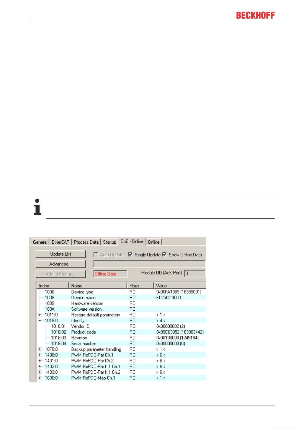
If a device has a CoE list, it is shown in the TwinCAT System Manager as a separate tab with a listing of the
elements:
Fig.13: “CoE Online” tab
EL511230 Version: 1.1
Page 31

Basics communication
The figure above shows the CoE objects available in device “EL2502”, ranging from 0x1000 to 0x1600. The
subindices for 0x1018 are expanded.
Data management and function “NoCoeStorage”
Some parameters, particularly the setting parameters of the slave, are configurable and writeable. This can
be done in write or read mode
• via the System Manager (Fig. “CoE Online” tab) by clicking
This is useful for commissioning of the system/slaves. Click on the row of the index to be
parameterized and enter a value in the “SetValue” dialog.
• from the control system/PLC via ADS, e.g. through blocks from the TcEtherCAT.lib library
This is recommended for modifications while the system is running or if no System Manager or
operating staff are available.
Data management
If slave CoE parameters are modified online, Beckhoff devices store any changes in a fail-safe
manner in the EEPROM, i.e. the modified CoE parameters are still available after a restart.
The situation may be different with other manufacturers.
An EEPROM is subject to a limited lifetime with respect to write operations. From typically 100,000
write operations onwards it can no longer be guaranteed that new (changed) data are reliably saved
or are still readable. This is irrelevant for normal commissioning. However, if CoE parameters are
continuously changed via ADS at machine runtime, it is quite possible for the lifetime limit to be
reached. Support for the NoCoeStorage function, which suppresses the saving of changed CoE values, depends on the firmware version.
Please refer to the technical data in this documentation as to whether this applies to the respective
device.
• If the function is supported: the function is activated by entering the code word 0x12345678 once
in CoE 0xF008 and remains active as long as the code word is not changed. After switching the
device on it is then inactive. Changed CoE values are not saved in the EEPROM and can thus
be changed any number of times.
• Function is not supported: continuous changing of CoE values is not permissible in view of the
lifetime limit.
Startup list
Changes in the local CoE list of the terminal are lost if the terminal is replaced. If a terminal is replaced with a new Beckhoff terminal, it will have the default settings. It is therefore advisable to link
all changes in the CoE list of an EtherCAT slave with the Startup list of the slave, which is processed whenever the EtherCAT fieldbus is started. In this way a replacement EtherCAT slave can
automatically be parameterized with the specifications of the user.
If EtherCAT slaves are used which are unable to store local CoE values permanently, the Startup
list must be used.
Recommended approach for manual modification of CoE parameters
• Make the required change in the System Manager
The values are stored locally in the EtherCAT slave
• If the value is to be stored permanently, enter it in the Startup list.
The order of the Startup entries is usually irrelevant.
EL5112 31Version: 1.1
Page 32

Basics communication
Fig.14: Startup list in the TwinCAT System Manager
The Startup list may already contain values that were configured by the System Manager based on the ESI
specifications. Additional application-specific entries can be created.
Online/offline list
While working with the TwinCAT System Manager, a distinction has to be made whether the EtherCAT
device is “available”, i.e. switched on and linked via EtherCAT and therefore online, or whether a
configuration is created offline without connected slaves.
In both cases a CoE list as shown in Fig. “CoE online tab” is displayed. The connectivity is shown as offline/
online.
• If the slave is offline
◦ The offline list from the ESI file is displayed. In this case modifications are not meaningful or
possible.
◦ The configured status is shown under Identity.
◦ No firmware or hardware version is displayed, since these are features of the physical device.
◦ Offline is shown in red.
Fig.15: Offline list
EL511232 Version: 1.1
Page 33
Basics communication
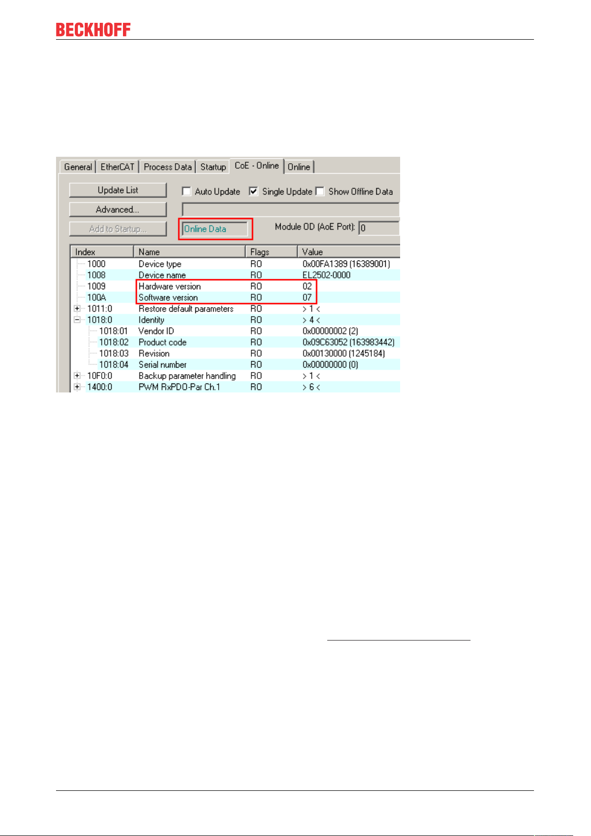
• If the slave is online
◦ The actual current slave list is read. This may take several seconds, depending on the size and
cycle time.
◦ The actual identity is displayed
◦ The firmware and hardware version of the equipment according to the electronic information is
displayed
◦ Online is shown in green.
Fig.16: Online list
Channel-based order
The CoE list is available in EtherCAT devices that usually feature several functionally equivalent channels.
For example, a 4-channel analog 0...10V input terminal also has four logical channels and therefore four
identical sets of parameter data for the channels. In order to avoid having to list each channel in the
documentation, the placeholder “n” tends to be used for the individual channel numbers.
In the CoE system 16 indices, each with 255 subindices, are generally sufficient for representing all channel
parameters. The channel-based order is therefore arranged in 16
dec
/10
steps. The parameter range
hex
0x8000 exemplifies this:
• Channel 0: parameter range 0x8000:00 ... 0x800F:255
• Channel 1: parameter range 0x8010:00 ... 0x801F:255
• Channel 2: parameter range 0x8020:00 ... 0x802F:255
• ...
This is generally written as 0x80n0.
Detailed information on the CoE interface can be found in the EtherCAT system documentation on the
Beckhoff website.
EL5112 33Version: 1.1
Page 34

Basics communication
3.6 Distributed Clock
The distributed clock represents a local clock in the EtherCAT slave controller (ESC) with the following
characteristics:
• Unit 1 ns
• Zero point 1.1.2000 00:00
• Size 64 bit (sufficient for the next 584 years; however, some EtherCAT slaves only offer 32-bit support,
i.e. the variable overflows after approx. 4.2 seconds)
• The EtherCAT master automatically synchronizes the local clock with the master clock in the EtherCAT
bus with a precision of < 100 ns.
For detailed information please refer to the EtherCAT system description.
EL511234 Version: 1.1
Page 35
Mounting and wiring
4 Mounting and wiring
4.1 Instructions for ESD protection
NOTE
Destruction of the devices by electrostatic discharge possible!
The devices contain components at risk from electrostatic discharge caused by improper handling.
• Please ensure you are electrostatically discharged and avoid touching the contacts of the device directly.
• Avoid contact with highly insulating materials (synthetic fibers, plastic film etc.).
• Surroundings (working place, packaging and personnel) should by grounded probably, when handling
with the devices.
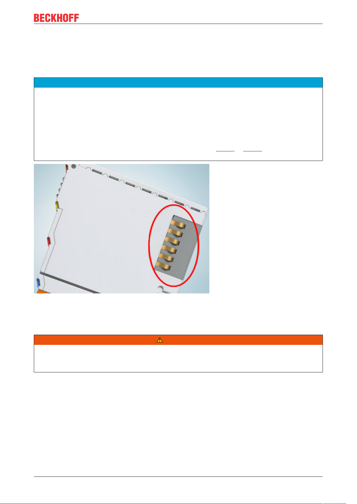
• Each assembly must be terminated at the right hand end with an EL9011 or EL9012 bus end cap, to ensure the protection class and ESD protection.
Fig.17: Spring contacts of the Beckhoff I/O components
4.2 Installation on mounting rails
WARNING
Risk of electric shock and damage of device!
Bring the bus terminal system into a safe, powered down state before starting installation, disassembly or
wiring of the bus terminals!
EL5112 35Version: 1.1
Page 36
Mounting and wiring
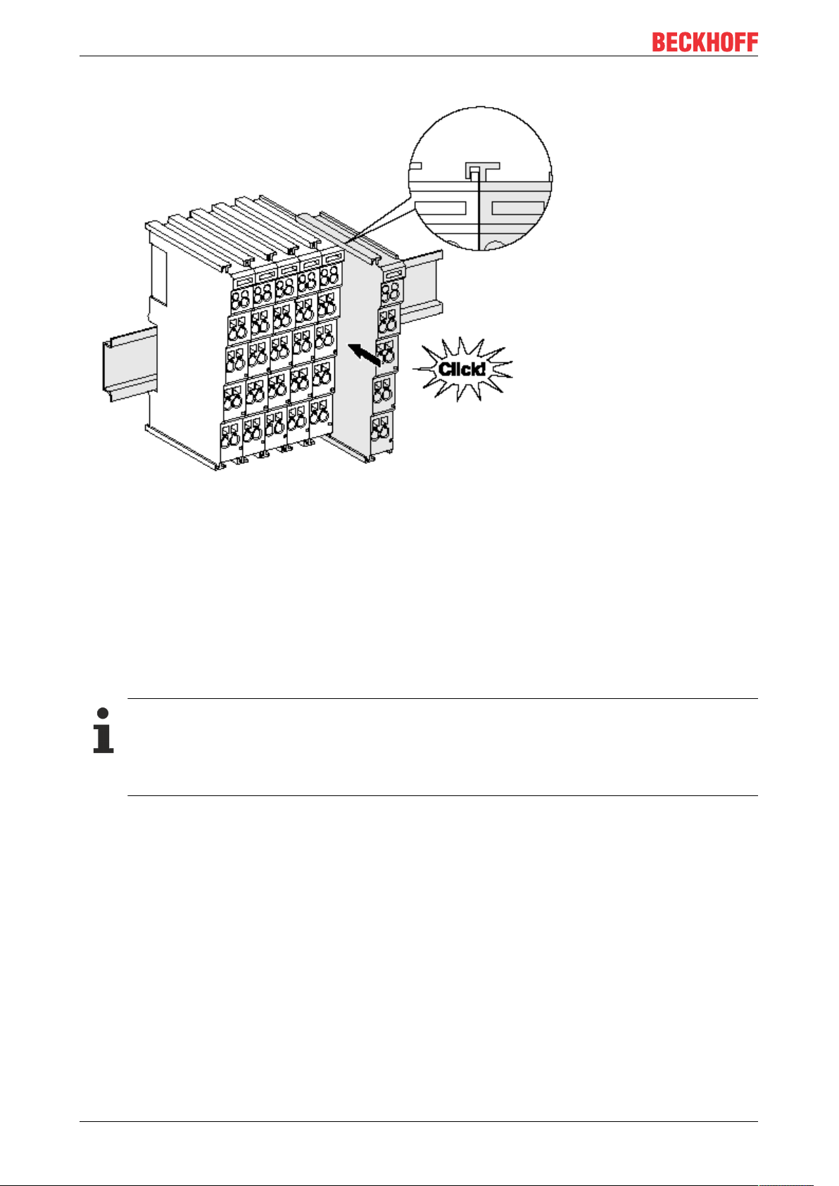
Assembly
Fig.18: Attaching on mounting rail
The bus coupler and bus terminals are attached to commercially available 35mm mounting rails (DIN rails
according to EN60715) by applying slight pressure:
1. First attach the fieldbus coupler to the mounting rail.
2. The bus terminals are now attached on the right-hand side of the fieldbus coupler. Join the components with tongue and groove and push the terminals against the mounting rail, until the lock clicks
onto the mounting rail.
If the terminals are clipped onto the mounting rail first and then pushed together without tongue and
groove, the connection will not be operational! When correctly assembled, no significant gap should
be visible between the housings.
Fixing of mounting rails
The locking mechanism of the terminals and couplers extends to the profile of the mounting rail. At
the installation, the locking mechanism of the components must not come into conflict with the fixing
bolts of the mounting rail. To mount the mounting rails with a height of 7.5mm under the terminals
and couplers, you should use flat mounting connections (e.g. countersunk screws or blind rivets).
EL511236 Version: 1.1
Page 37
Mounting and wiring
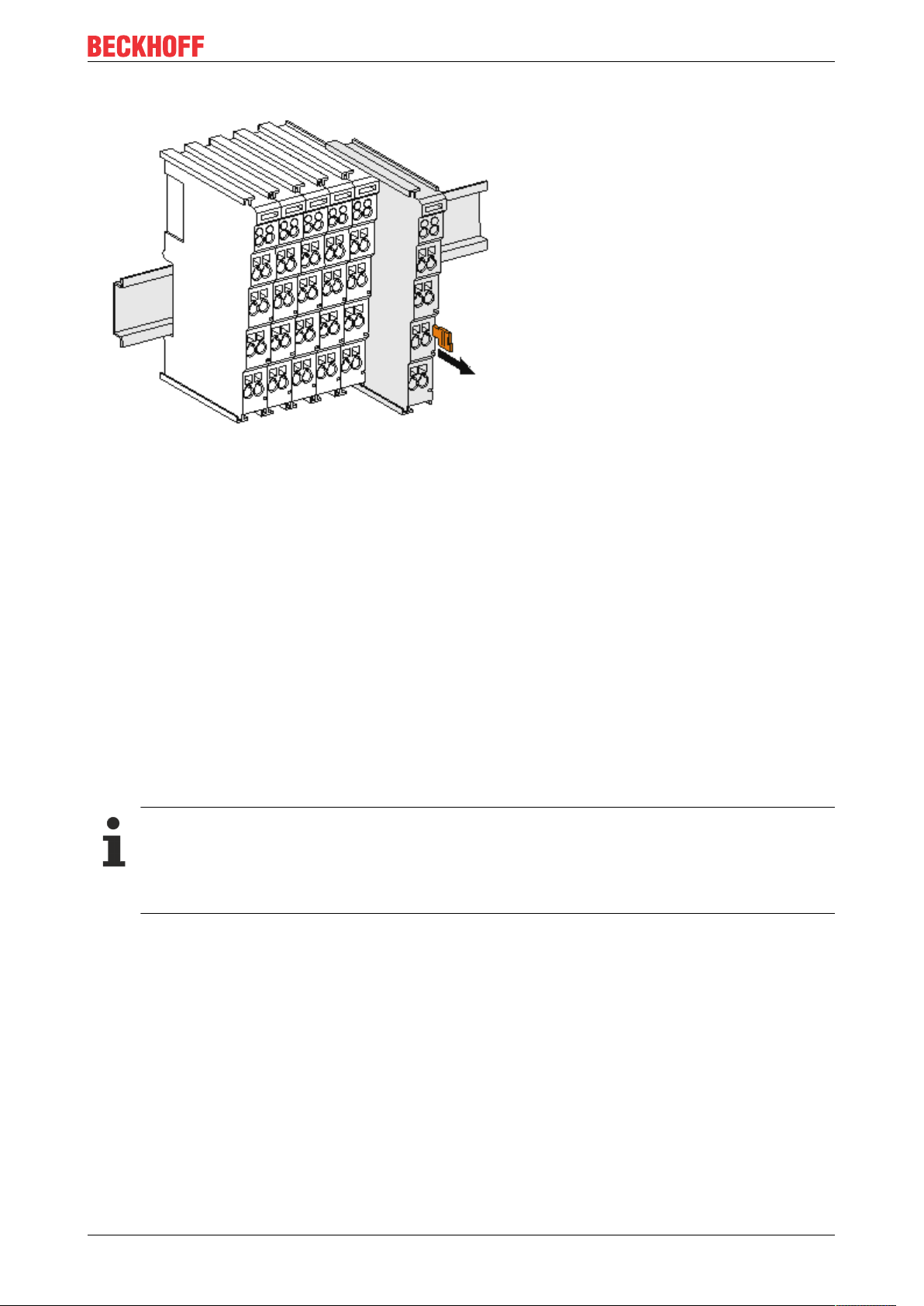
Disassembly
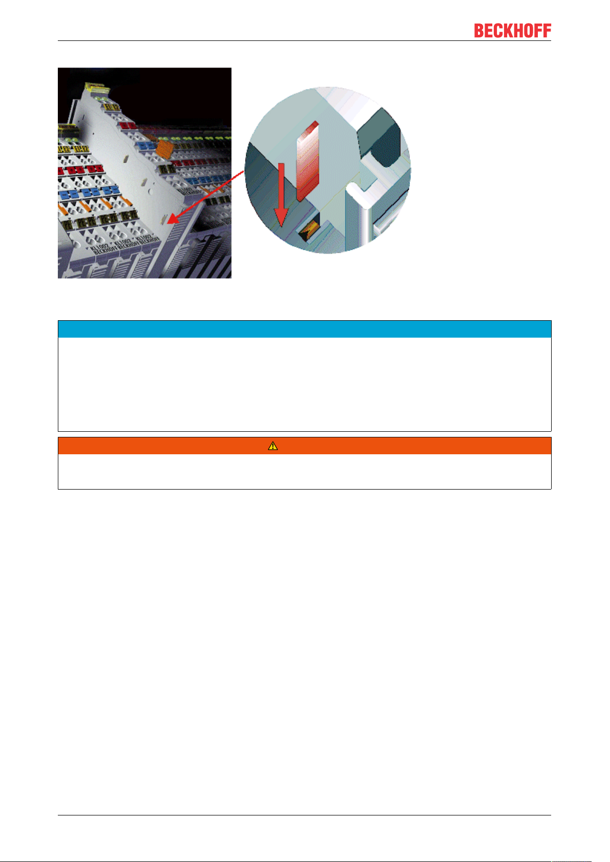
Fig.19: Disassembling of terminal
Each terminal is secured by a lock on the mounting rail, which must be released for disassembly:
1. Pull the terminal by its orange-colored lugs approximately 1cm away from the mounting rail. In doing
so for this terminal the mounting rail lock is released automatically and you can pull the terminal out of
the bus terminal block easily without excessive force.
2. Grasp the released terminal with thumb and index finger simultaneous at the upper and lower grooved
housing surfaces and pull the terminal out of the bus terminal block.
Connections within a bus terminal block
The electric connections between the Bus Coupler and the Bus Terminals are automatically realized by
joining the components:
• The six spring contacts of the K-Bus/E-Bus deal with the transfer of the data and the supply of the Bus
Terminal electronics.
• The power contacts deal with the supply for the field electronics and thus represent a supply rail within
the bus terminal block. The power contacts are supplied via terminals on the Bus Coupler (up to 24V)
or for higher voltages via power feed terminals.
Power Contacts
During the design of a bus terminal block, the pin assignment of the individual Bus Terminals must
be taken account of, since some types (e.g. analog Bus Terminals or digital 4-channel Bus Terminals) do not or not fully loop through the power contacts. Power Feed Terminals (KL91xx, KL92xx
or EL91xx, EL92xx) interrupt the power contacts and thus represent the start of a new supply rail.
PE power contact
The power contact labeled PE can be used as a protective earth. For safety reasons this contact mates first
when plugging together, and can ground short-circuit currents of up to 125A.
EL5112 37Version: 1.1
Page 38
Mounting and wiring
Fig.20: Power contact on left side
NOTE
Possible damage of the device
Note that, for reasons of electromagnetic compatibility, the PE contacts are capacitatively coupled to the
mounting rail. This may lead to incorrect results during insulation testing or to damage on the terminal (e.g.
disruptive discharge to the PE line during insulation testing of a consumer with a nominal voltage of 230V).
For insulation testing, disconnect the PE supply line at the Bus Coupler or the Power Feed Terminal! In order to decouple further feed points for testing, these Power Feed Terminals can be released and pulled at
least 10mm from the group of terminals.
WARNING
Risk of electric shock!
The PE power contact must not be used for other potentials!
EL511238 Version: 1.1
Page 39

Mounting and wiring
4.3 Installation instructions for enhanced mechanical load capacity
WARNING
Risk of injury through electric shock and damage to the device!
Bring the Bus Terminal system into a safe, de-energized state before starting mounting, disassembly or
wiring of the Bus Terminals!
Additional checks
The terminals have undergone the following additional tests:
Verification Explanation
Vibration 10 frequency runs in 3 axes
6 Hz < f < 60 Hz displacement 0.35 mm, constant amplitude
60.1Hz<f<500Hz acceleration 5g, constant amplitude
Shocks 1000 shocks in each direction, in 3 axes
25 g, 6 ms
Additional installation instructions
For terminals with enhanced mechanical load capacity, the following additional installation instructions apply:
• The enhanced mechanical load capacity is valid for all permissible installation positions
• Use a mounting rail according to EN 60715 TH35-15
• Fix the terminal segment on both sides of the mounting rail with a mechanical fixture, e.g. an earth
terminal or reinforced end clamp
• The maximum total extension of the terminal segment (without coupler) is:
64 terminals (12mm mounting with) or 32 terminals (24mm mounting with)
• Avoid deformation, twisting, crushing and bending of the mounting rail during edging and installation of
the rail
• The mounting points of the mounting rail must be set at 5 cm intervals
• Use countersunk head screws to fasten the mounting rail
• The free length between the strain relief and the wire connection should be kept as short as possible. A
distance of approx. 10cm should be maintained to the cable duct.
4.4 Connection
4.4.1 Connection system
WARNING
Risk of electric shock and damage of device!
Bring the bus terminal system into a safe, powered down state before starting installation, disassembly or
wiring of the bus terminals!
Overview
The bus terminal system offers different connection options for optimum adaptation to the respective
application:
• The terminals of ELxxxx and KLxxxx series with standard wiring include electronics and connection
level in a single enclosure.
EL5112 39Version: 1.1
Page 40

Mounting and wiring
• The terminals of ESxxxx and KSxxxx series feature a pluggable connection level and enable steady
wiring while replacing.
• The High Density Terminals (HD Terminals) include electronics and connection level in a single
enclosure and have advanced packaging density.
Standard wiring (ELxxxx / KLxxxx)
Fig.21: Standard wiring
The terminals of ELxxxx and KLxxxx series have been tried and tested for years.
They feature integrated screwless spring force technology for fast and simple assembly.
Pluggable wiring (ESxxxx / KSxxxx)
Fig.22: Pluggable wiring
The terminals of ESxxxx and KSxxxx series feature a pluggable connection level.
The assembly and wiring procedure is the same as for the ELxxxx and KLxxxx series.
The pluggable connection level enables the complete wiring to be removed as a plug connector from the top
of the housing for servicing.
The lower section can be removed from the terminal block by pulling the unlocking tab.
Insert the new component and plug in the connector with the wiring. This reduces the installation time and
eliminates the risk of wires being mixed up.
The familiar dimensions of the terminal only had to be changed slightly. The new connector adds about 3
mm. The maximum height of the terminal remains unchanged.
A tab for strain relief of the cable simplifies assembly in many applications and prevents tangling of individual
connection wires when the connector is removed.
Conductor cross sections between 0.08mm2 and 2.5mm2 can continue to be used with the proven spring
force technology.
The overview and nomenclature of the product names for ESxxxx and KSxxxx series has been retained as
known from ELxxxx and KLxxxx series.
EL511240 Version: 1.1
Page 41

Mounting and wiring
High Density Terminals (HD Terminals)
Fig.23: High Density Terminals
The terminals from these series with 16 terminal points are distinguished by a particularly compact design,
as the packaging density is twice as large as that of the standard 12mm bus terminals. Massive conductors
and conductors with a wire end sleeve can be inserted directly into the spring loaded terminal point without
tools.
Wiring HD Terminals
The High Density Terminals of the ELx8xx and KLx8xx series doesn't support pluggable wiring.
Ultrasonically “bonded” (ultrasonically welded) conductors
Ultrasonically “bonded” conductors
It is also possible to connect the Standard and High Density Terminals with ultrasonically
“bonded” (ultrasonically welded) conductors. In this case, please note the tables concerning the
wire-size width!
EL5112 41Version: 1.1
Page 42

Mounting and wiring
4.4.2 Wiring
WARNING
Risk of electric shock and damage of device!
Bring the bus terminal system into a safe, powered down state before starting installation, disassembly or
wiring of the bus terminals!
Terminals for standard wiring ELxxxx/KLxxxx and for pluggable wiring ESxxxx/KSxxxx
Fig.24: Connecting a cable on a terminal point
Up to eight terminal points enable the connection of solid or finely stranded cables to the bus terminal. The
terminal points are implemented in spring force technology. Connect the cables as follows:
1. Open a terminal point by pushing a screwdriver straight against the stop into the square opening
above the terminal point. Do not turn the screwdriver or move it alternately (don't toggle).
2. The wire can now be inserted into the round terminal opening without any force.
3. The terminal point closes automatically when the pressure is released, holding the wire securely and
permanently.
See the following table for the suitable wire size width.
Terminal housing ELxxxx, KLxxxx ESxxxx, KSxxxx
Wire size width (single core wires) 0.08 ... 2.5mm
Wire size width (fine-wire conductors) 0.08 ... 2.5mm
Wire size width (conductors with a wire end sleeve) 0.14 ... 1.5mm
2
2
2
0.08 ... 2.5mm
0,08 ... 2.5mm
0.14 ... 1.5mm
2
2
2
Wire stripping length 8 ... 9mm 9 ... 10mm
High Density Terminals (HD Terminals [}41]) with 16 terminal points
The conductors of the HD Terminals are connected without tools for single-wire conductors using the direct
plug-in technique, i.e. after stripping the wire is simply plugged into the terminal point. The cables are
released, as usual, using the contact release with the aid of a screwdriver. See the following table for the
suitable wire size width.
EL511242 Version: 1.1
Page 43

Mounting and wiring
Terminal housing High Density Housing
Wire size width (single core wires) 0.08 ... 1.5mm
Wire size width (fine-wire conductors) 0.25 ... 1.5mm
Wire size width (conductors with a wire end sleeve) 0.14 ... 0.75mm
Wire size width (ultrasonically “bonded" conductors) only 1.5mm
2
2
2
2
Wire stripping length 8 ... 9mm
4.4.3 Shielding
Shielding
Encoder, analog sensors and actors should always be connected with shielded, twisted paired
wires.
4.5 Installation positions
NOTE
Constraints regarding installation position and operating temperature range
Please refer to the technical data for a terminal to ascertain whether any restrictions regarding the installation position and/or the operating temperature range have been specified. When installing high power dissipation terminals ensure that an adequate spacing is maintained between other components above and below the terminal in order to guarantee adequate ventilation!
Optimum installation position (standard)
The optimum installation position requires the mounting rail to be installed horizontally and the connection
surfaces of the EL/KL terminals to face forward (see Fig. Recommended distances for standard installation
position). The terminals are ventilated from below, which enables optimum cooling of the electronics through
convection. “From below” is relative to the acceleration of gravity.
EL5112 43Version: 1.1
Page 44

Mounting and wiring
Fig.25: Recommended distances for standard installation position
Compliance with the distances shown in Fig. Recommended distances for standard installation position is
recommended.
Other installation positions
All other installation positions are characterized by different spatial arrangement of the mounting rail - see
Fig Other installation positions.
The minimum distances to ambient specified above also apply to these installation positions.
EL511244 Version: 1.1
Page 45

Fig.26: Other installation positions
Mounting and wiring
EL5112 45Version: 1.1
Page 46

Mounting and wiring
4.6 Positioning of passive Terminals
Hint for positioning of passive terminals in the bus terminal block
EtherCAT Terminals (ELxxxx / ESxxxx), which do not take an active part in data transfer within the
bus terminal block are so called passive terminals. The passive terminals have no current consumption out of the E-Bus.
To ensure an optimal data transfer, you must not directly string together more than two passive terminals!
Examples for positioning of passive terminals (highlighted)
Fig.27: Correct positioning
Fig.28: Incorrect positioning
EL511246 Version: 1.1
Page 47

4.7 EL5112 - Connection
Mounting and wiring
Fig.29: EL5112 - Connection
Terminal point No. Comment
Single-channel mode 1xABC Two-channel mode 2xAB
A1 1 Encoder input A1 Encoder input A1
B1 2 Encoder input B1 Encoder input B1
C1 / A2 3 Encoder input C1 Encoder input A2
Status input / B2 4 Status input
The Status Input input is internally connected to 5V
via a pull-up resistor. The encoder fault signal output
must actively pull the signal against GND.
External power supply is not recommended. If an external supply is used, the maximum permitted voltage
is 5V against GND.
+ Ue 5 Encoder supply (5V default, parameterizable 12V,
24V)
-Uo 6 0Vencoder supply 0Vencoder supply
Latch 7 Latch extern input Gate/Latch combination input for encoder 1
n.c. 8 Do not connect the terminal point Do not connect the terminal point
A1 9 Encoder input A1 (Encoder 1) Encoder input A1 (Encoder 1)
B1 10 Encoder input B1 (Encoder 1) Encoder input B1 (Encoder 1)
C1 / A2 11 Encoder input C1 (Encoder 1) Encoder input A2 (Encoder 2)
B2 12 Do not connect the terminal point Encoder input B2 (Encoder 2)
+ Ue 13 Encoder supply (5V default, parameterizable 12V,
24V)
-Uo 14 0Vencoder supply 0Vencoder supply
Gate 15 Input gate, can also be used as external latch 2 input
for encoder 1
n.c. 16 Do not connect the terminal point Do not connect the terminal point
Encoder input B2
Encoder supply (5V default, parameterizable 12V,
24V)
Encoder supply (5V default, parameterizable 12V,
24V)
Gate/Latch combination input for encoder 2
Setting the encoder supply via index 0x8001:17 [}228]
The encoder supply is set centrally for both terminal channels via the index 0x8001:17 [}228] (channel 1). The corresponding index 0x8011:17 of the second channel has no parameterization function.
EL5112 47Version: 1.1
Page 48

Mounting and wiring
NOTE
Setting the encoder supply voltage
• Before switching to a higher voltage, make sure that the connected encoders support the selected voltage range!
• To write to 0x80n1:17 "Supply voltage" you have to set the value 0x72657375 (ASCII: "user") in index
0xF008 [}256] "Code word".
EL511248 Version: 1.1
Page 49

Mounting and wiring
4.7.1 Single-channel mode (1 x A, B, C)
4.7.1.1 RS422 mode
NOTE
Differential and single-ended connection
The RS422 signal transmits a differential voltage, which makes the signal less sensitive to interference
compared to a single-ended signal.
If the encoder signal is to be transmitted over longer distances or at higher frequencies, an encoder with
RS422 signals is recommended.
Shielded and twisted pair cables should be used.
Connection of RS422 encoders with or without zero pulse
Fig.30: Connection of RS422 encoders with zero pulse in single-channel mode
Connection instructions
• When using an encoder without zero pulse C, the terminal points for the C track are not connected.
EL5112 49Version: 1.1
Page 50
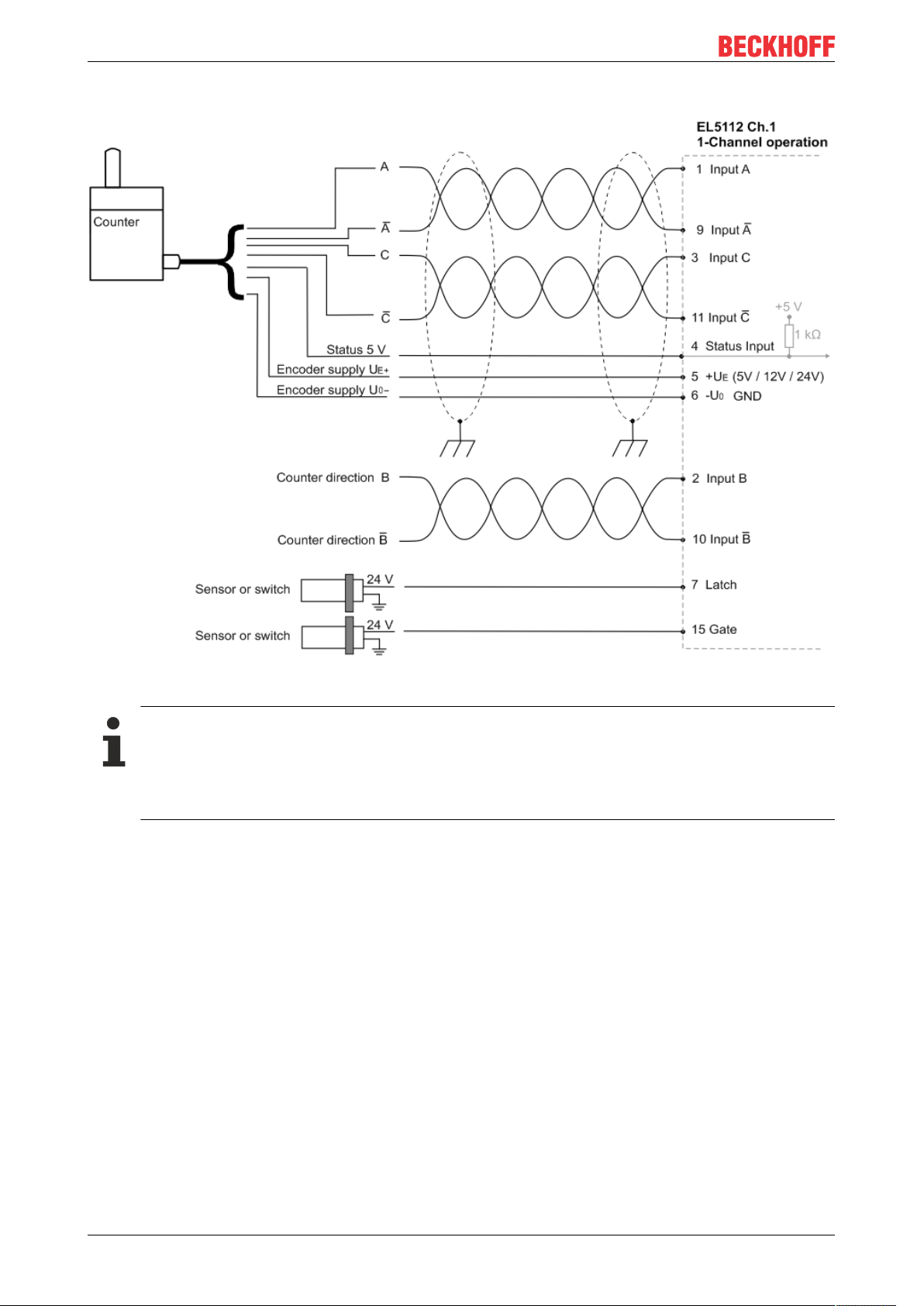
Mounting and wiring
Connection of RS422 counters / pulse generators with or without zero pulse
Fig.31: Connection of RS422 counter / pulse generators with zero pulse in single-channel mode
Connection instructions
• If a counter / pulse generator is connected, the B track determines the counting direction.
In RS422 mode a differential signal is expected on the B track.
• When using a counter / pulse generator without zero pulse C, the terminal points for the C track
are not connected.
EL511250 Version: 1.1
Page 51
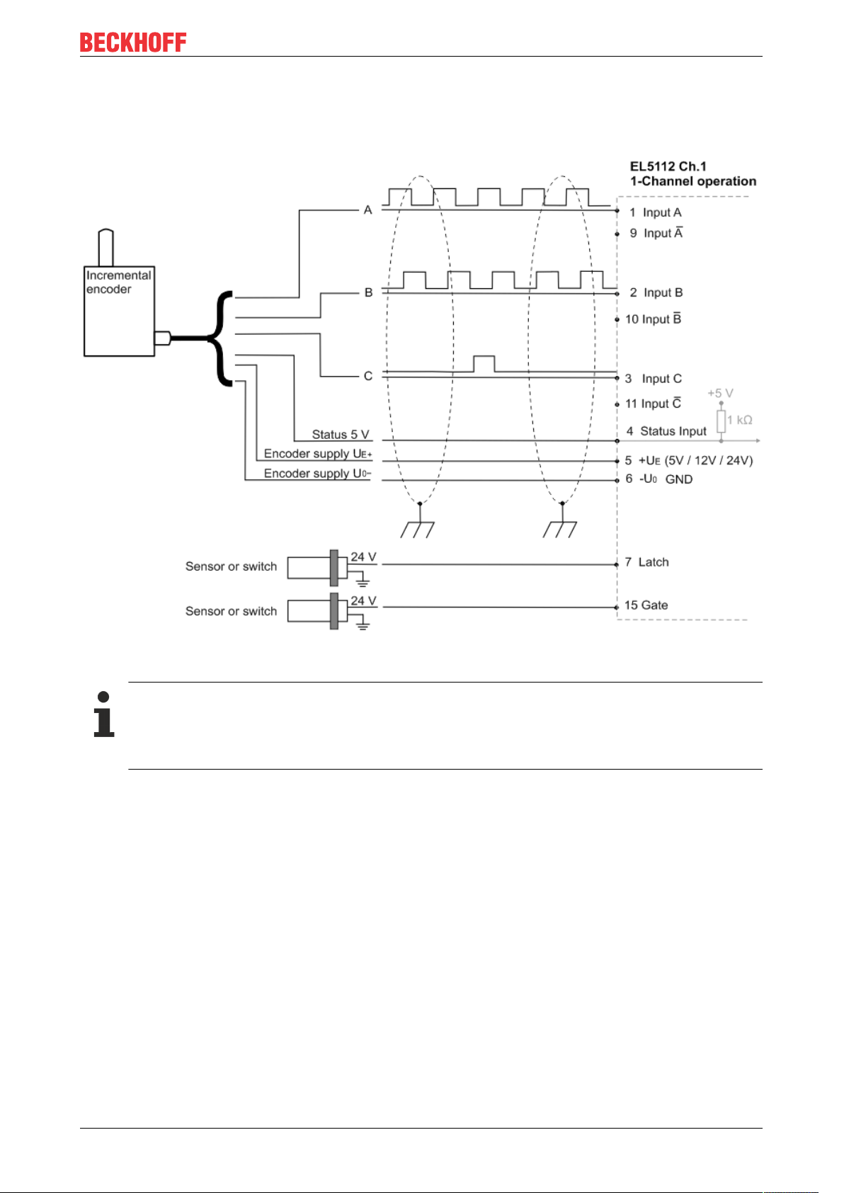
4.7.1.2 TTL mode
Connection of TTL encoders with or without zero pulse
Mounting and wiring
Fig.32: Connection of encoders in TTL mode with zero pulse in single-channel mode
Connection instructions
• In TTL mode the inverse inputs are not connected.
• When using an encoder without zero pulse C, the terminal points for the C track are not connected.
EL5112 51Version: 1.1
Page 52
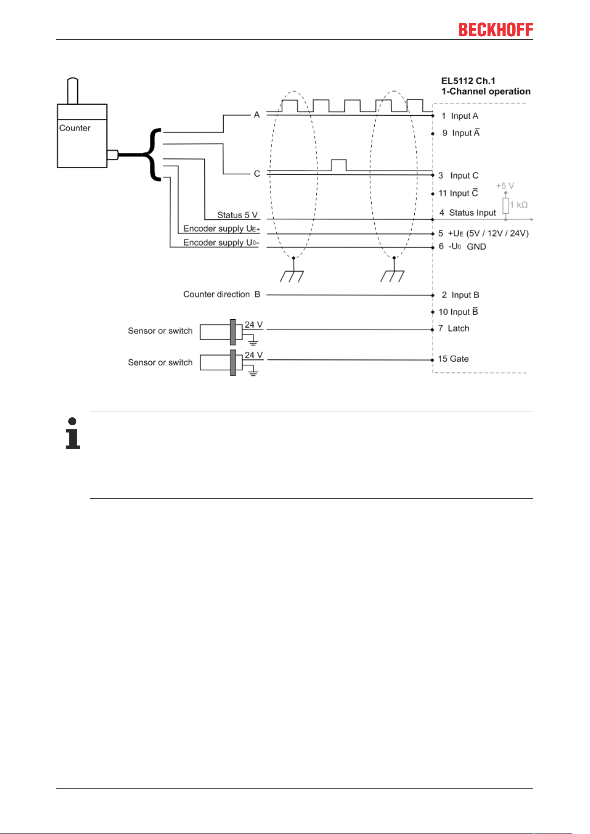
Mounting and wiring
Connection of TTL counters / pulse generators with or without zero pulse
Fig.33: Connection of counters / pulse generators in TTL mode with zero pulse in single-channel mode
Connection instructions
• In TTL mode the inverse inputs are not connected.
• If a counter / pulse generator is connected, the B track determines the counting direction.
Input B is not connected.
• When using a counter / pulse generator without zero pulse C, the terminal points for the C track
are not connected.
EL511252 Version: 1.1
Page 53

4.7.1.3 Open Collector mode
Connection of Open Collector encoders with or without zero pulse
Mounting and wiring
Fig.34: Connection of encoders in Open Collector mode with zero pulse in single-channel mode
Connection instructions
• In Open Collector mode the inverse inputs are not connected.
• When using an encoder without zero pulse C, the terminal points for the C track are not connected.
EL5112 53Version: 1.1
Page 54
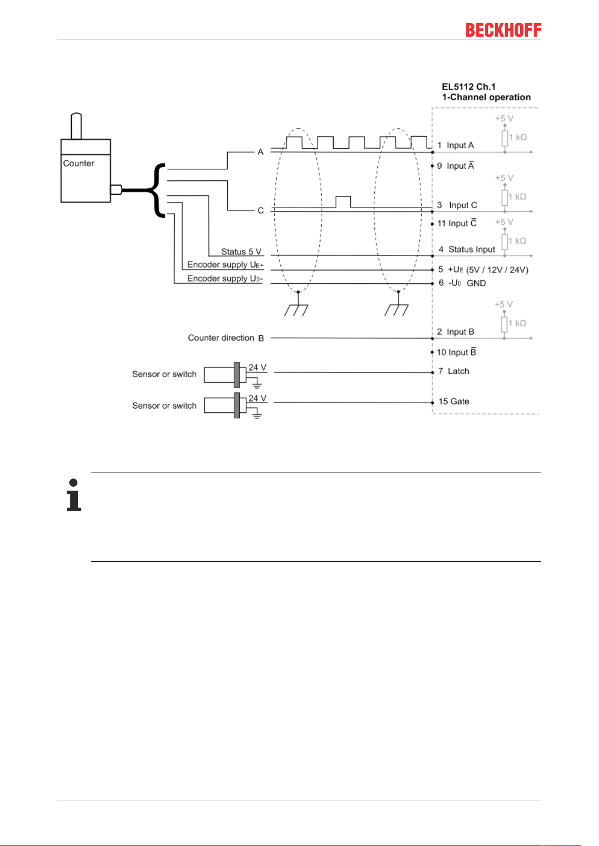
Mounting and wiring
Connection of Open Collector counters / pulse generators with or without zero pulse
Fig.35: Connection of counters / pulse generators in Open Collector mode with zero pulse in single-channel
mode
Connection instructions
• In Open Collector mode the inverse inputs are not connected.
• If a counter / pulse generator is connected, the B track determines the counting direction.
Input B is not connected.
• When using a counter / pulse generator without zero pulse C, the terminal points for the C track
are not connected.
EL511254 Version: 1.1
Page 55

Mounting and wiring
4.7.2 Two-channel mode (2 x A, B)
4.7.2.1 RS422 mode
NOTE
Differential and single-ended connection
The RS422 signal transmits a differential voltage, which makes the signal less sensitive to interference
compared to a single-ended signal.
If the encoder signal is to be transmitted over longer distances or at higher frequencies, an encoder with
RS422 signals is recommended.
Shielded and twisted pair cables should be used.
Connection of RS422 encoders without zero pulse in two-channel mode
Fig.36: Connection of encoders in RS422 mode without zero pulse in two-channel mode
Connection instructions
• In two-channel mode only encoders without zero pulse C can be used. The terminal points for
the C track are assigned the signals of the second A track.
EL5112 55Version: 1.1
Page 56
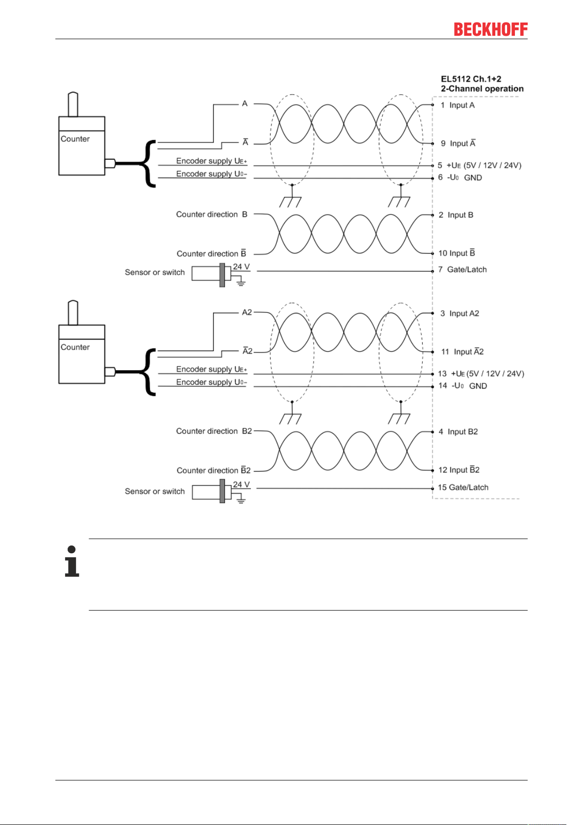
Mounting and wiring
Connection of RS422 counters / pulse generators without zero pulse in two-channel mode
Fig.37: Connection of counters / pulse generators in RS422 mode without zero pulse in two-channel mode
Connection instructions
• If a counter / pulse generator is connected, the B track determines the counting direction.
In RS422 mode a differential signal is expected on the B track.
• Only counters / pulse generators without zero pulse are suitable for use in two-channel mode.
The terminal points of the C track are assigned the signals of the second A track.
EL511256 Version: 1.1
Page 57
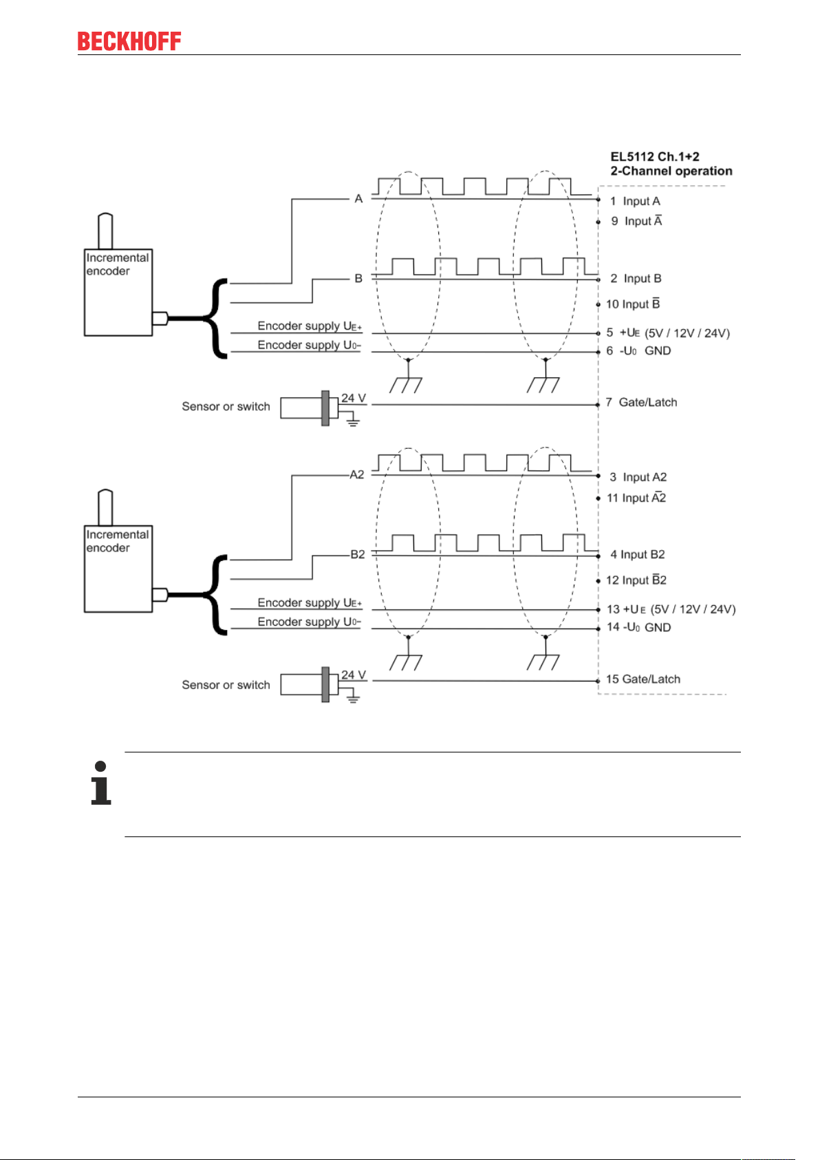
4.7.2.2 TTL mode
Connection of TTL encoders without zero pulse in two-channel mode
Mounting and wiring
Fig.38: Connection of encoders in TTL mode without zero pulse in two-channel mode
Connection instructions
• In TTL mode the inverse inputs are not connected.
• Only encoders without zero pulse are suitable for use in two-channel mode. The terminal points
for the C track are assigned the signals of the second A track.
EL5112 57Version: 1.1
Page 58

Mounting and wiring
Connection of TTL counters / pulse generators without zero pulse in two-channel mode
Fig.39: Connection of counters / pulse generators in TTL mode without zero pulse in two-channel mode
Connection instructions
• In TTL mode the inverse inputs are not connected.
• If a counter / pulse generator is connected, the B track determines the counting direction.
Input B is not connected.
• Only counters / pulse generators without zero pulse are suitable for use in two-channel mode.
The terminal points for the C track are assigned the signals of the second A track.
EL511258 Version: 1.1
Page 59

4.7.2.3 Open Collector mode
Connection of Open Collector encoders without zero pulse in two-channel mode
Mounting and wiring
Fig.40: Connection of encoders in Open Collector mode without zero pulse in two-channel mode
Connection instructions
• In Open Collector mode the inverse inputs are not connected.
• Only encoders without zero pulse are suitable for use in two-channel mode. The terminal points
for the C track are assigned the signals of the second A track.
EL5112 59Version: 1.1
Page 60

Mounting and wiring
Connection of Open Collector counters / pulse generators without zero pulse in two-channel mode
Fig.41: Connection of counters / pulse generators in Open Collector mode without zero pulse in two-channel
mode
Connection instructions
• In Open Collector mode the inverse inputs are not connected.
• If a counter / pulse generator is connected, the B track determines the counting direction.
Input B is not connected.
• Only counters / pulse generators without zero pulse are suitable for use in two-channel mode.
The terminal points for the C track are assigned the signals of the second A track.
EL511260 Version: 1.1
Page 61

4.8 EL5112 - LEDs
Single-channel mode (1xABC)
Fig.42: EL5112 - LEDs in single-channel mode
Mounting and wiring
No. Name Color Description
1 A1 green, red Green: indicates TRUE level
2 B1
3 C1
4 Status Input red Fault signal input from encoder. Input is internally connected to 5V via a pull-up resistor. The en-
5 PowerEnc. green Operating voltage display for incremental encoder power supply
7 Latch green is lit, if a signal (+24V) is connected to the latch input
9 Run green This LED indicates the terminal's operating state:
10 Diag red Initialization process active or state of the EtherCAT State Machine: BOOT
15 Gate/Latch green is lit if a signal (+24V) is present at the gate/latch input
Red: There is a broken wire at the respective input. Diagnosis is only possible if the following
three conditions are met.
• The corresponding input is differentially wired, i.e.:
„Counter mode“ 0x8001:1D =0 (Encoder RS422 (diff. Input))
or
„Counter mode“ 0x8001:1D =1 (Counter RS422 (diff. Input))
• "Error Detection" for the respective input is enabled:
„Error Detection A“ 0x8000:0B = TRUE
„Error Detection B“ 0x8000:0C = TRUE
„Error Detection C“ 0x8000:0D = TRUE
• The differential voltage V
coder output must actively pull the signal against GND.
on Output active at the encoder, a fault message is present at the encoder
off Output not active at the encoder; no fault message is present
off
flashing State of the EtherCAT State Machine: PREOP = function for mailbox communication
Single flash
on State of the EtherCAT State Machine: OP = normal operating state; mailbox and
State of the EtherCAT State Machine [}28]: INIT = initialization of the terminal or
BOOTSTRAP = function for firmware updates [}257] of the terminal
and different default settings set
State of the EtherCAT State Machine: SAFEOP = verification of the Sync Manager
[}113] channels and the distributed clocks.
Outputs remain in safe state
process data communication is possible
is typically less than 0.67V (subject to change).
ID Low
EL5112 61Version: 1.1
Page 62

Mounting and wiring
Two-channel mode (2xAB)
Fig.43: EL5112 - LEDs in two-channel mode
No. Name Color Description
1 A1 green, red Green: indicates TRUE level
2 B1
3 A2
4 B2
5 PowerEnc. green Operating voltage display for incremental encoder power supply
7 Latch green is lit, if a signal (+24V) is connected to the latch input
9 Run green This LED indicates the terminal's operating state:
10 Diag red Initialization process active or state of the EtherCAT State Machine: BOOT
15 Gate/Latch green is lit if a signal (+24V) is present at the gate/latch input
Red: There is a broken wire at the respective input. Diagnosis is only possible if the following
three conditions are met.
• The corresponding input is differentially wired, i.e.:
„Counter mode“ 0x8001:1D =0 (Encoder RS422 (diff. Input))
or
„Counter mode“ 0x8001:1D =1 (Counter RS422 (diff. Input))
• "Error Detection" for the respective input is enabled:
„Error Detection A“ 0x8000:0B = TRUE
„Error Detection B“ 0x8000:0C = TRUE
• The differential voltage V
off
flashing State of the EtherCAT State Machine: PREOP = function for mailbox communication
Single flash
on State of the EtherCAT State Machine: OP = normal operating state; mailbox and
State of the EtherCAT State Machine [}28]: INIT = initialization of the terminal or
BOOTSTRAP = function for firmware updates [}257] of the terminal
and different default settings set
State of the EtherCAT State Machine: SAFEOP = verification of the Sync Manager
[}113] channels and the distributed clocks.
Outputs remain in safe state
process data communication is possible
is typically less than 0.67V (subject to change).
ID Low
EL511262 Version: 1.1
Page 63

Commissioning
5 Commissioning
5.1 TwinCAT Quick Start
TwinCAT is a development environment for real-time control including multi-PLC system, NC axis control,
programming and operation. The whole system is mapped through this environment and enables access to a
programming environment (including compilation) for the controller. Individual digital or analog inputs or
outputs can also be read or written directly, in order to verify their functionality, for example.
For further information please refer to http://infosys.beckhoff.com:
• EtherCAT Systemmanual:
Fieldbus Components → EtherCAT Terminals → EtherCAT System Documentation → Setup in the
TwinCAT System Manager
• TwinCAT2 → TwinCAT System Manager → I/O - Configuration
• In particular, TwinCAT driver installation:
Fieldbus components → Fieldbus Cards and Switches → FC900x – PCI Cards for Ethernet →
Installation
Devices contain the terminals for the actual configuration. All configuration data can be entered directly via
editor functions (offline) or via the “Scan” function (online):
• “offline”: The configuration can be customized by adding and positioning individual components.
These can be selected from a directory and configured.
◦ The procedure for offline mode can be found under http://infosys.beckhoff.com:
TwinCAT2 → TwinCAT System Manager → IO - Configuration → Adding an I/O Device
• “online”: The existing hardware configuration is read
◦ See also http://infosys.beckhoff.com:
Fieldbus components → Fieldbus cards and switches → FC900x – PCI Cards for Ethernet →
Installation → Searching for devices
The following relationship is envisaged from user PC to the individual control elements:
EL5112 63Version: 1.1
Page 64
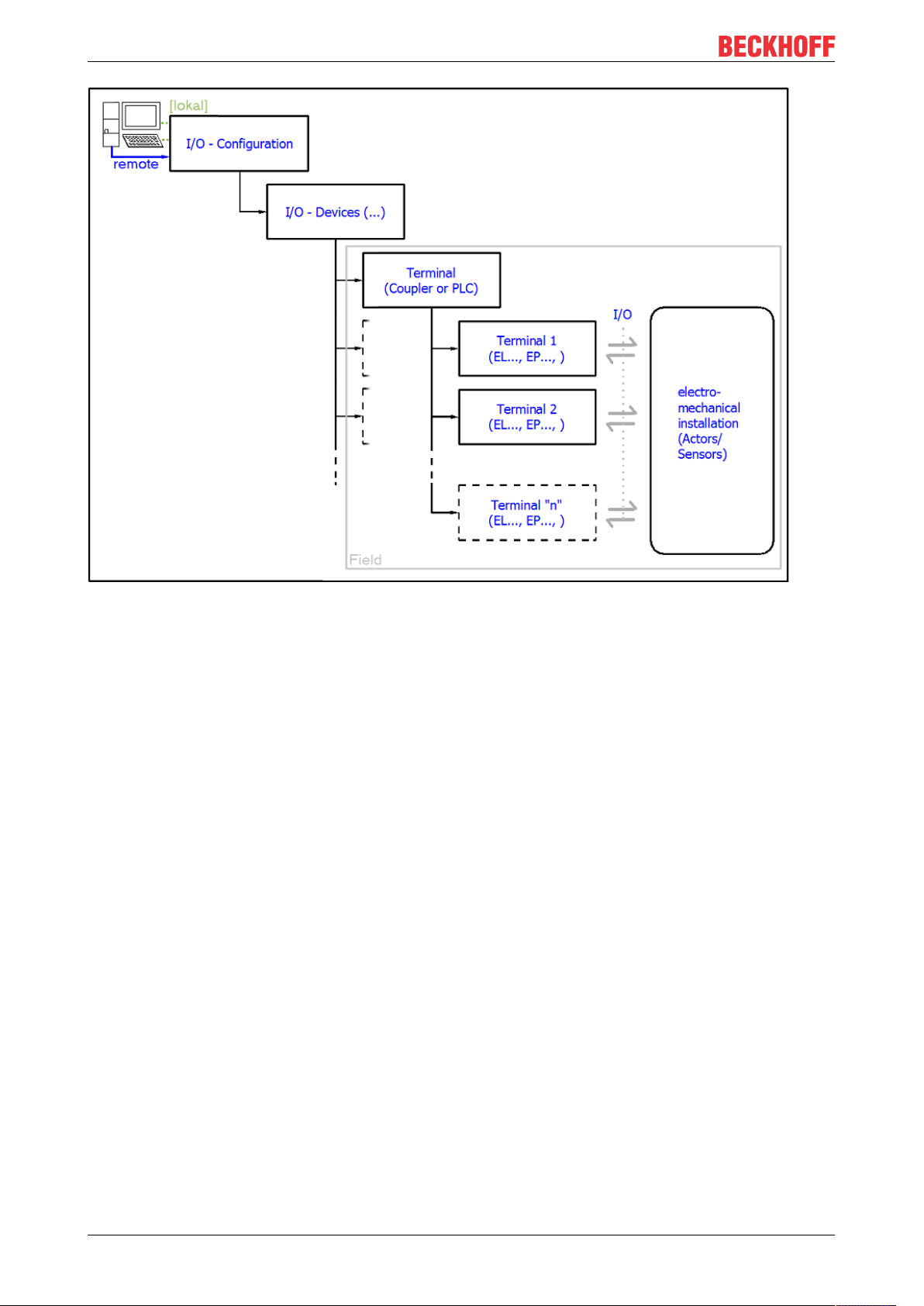
Commissioning
Fig.44: Relationship between user side (commissioning) and installation
The user inserting of certain components (I/O device, terminal, box...) is the same in TwinCAT2 and
TwinCAT3. The descriptions below relate to the online procedure.
Sample configuration (actual configuration)
Based on the following sample configuration, the subsequent subsections describe the procedure for
TwinCAT2 and TwinCAT3:
• Control system (PLC) CX2040 including CX2100-0004 power supply unit
• Connected to the CX2040 on the right (E-bus):
EL1004 (4-channel digital input terminal 24VDC)
• Linked via the X001 port (RJ-45): EK1100 EtherCAT Coupler
• Connected to the EK1100 EtherCAT coupler on the right (E-bus):
EL2008 (8-channel digital output terminal 24VDC;0.5A)
• (Optional via X000: a link to an external PC for the user interface)
EL511264 Version: 1.1
Page 65
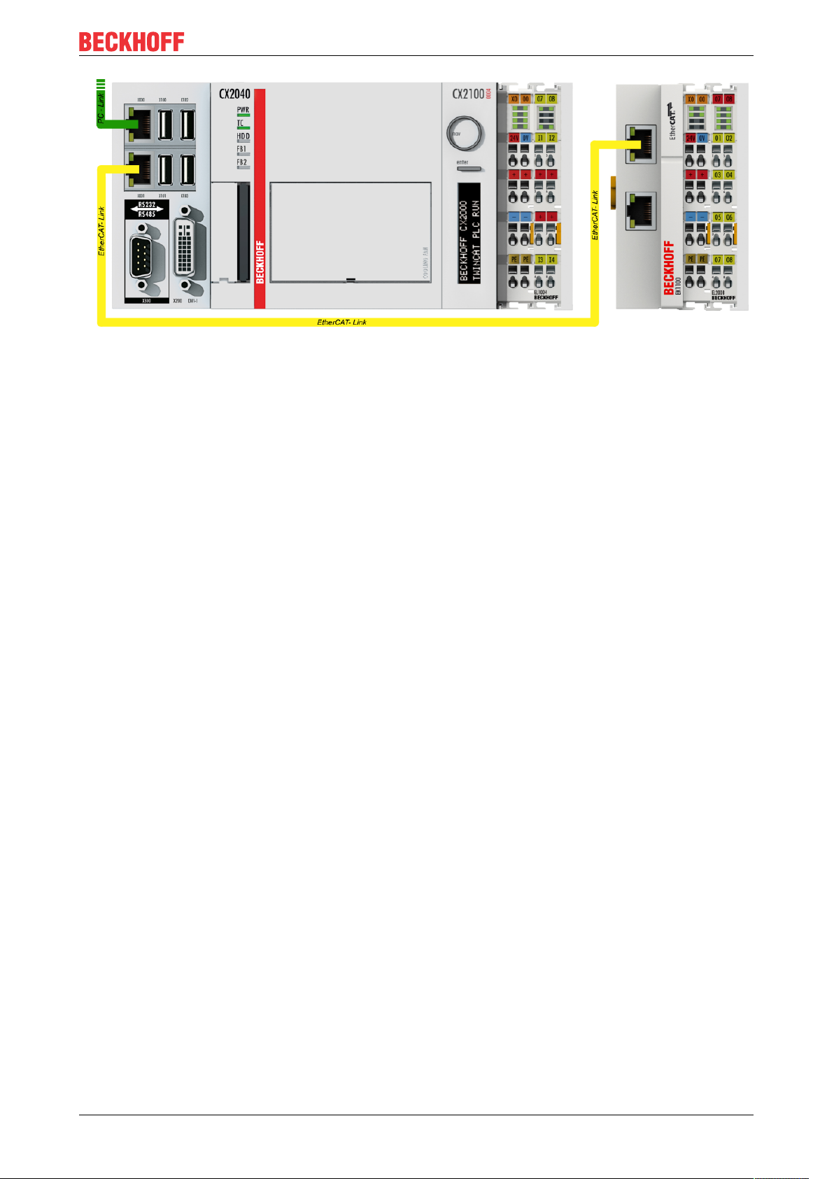
Commissioning
Fig.45: Control configuration with Embedded PC, input (EL1004) and output (EL2008)
Note that all combinations of a configuration are possible; for example, the EL1004 terminal could also be
connected after the coupler, or the EL2008 terminal could additionally be connected to the CX2040 on the
right, in which case the EK1100 coupler wouldn’t be necessary.
EL5112 65Version: 1.1
Page 66
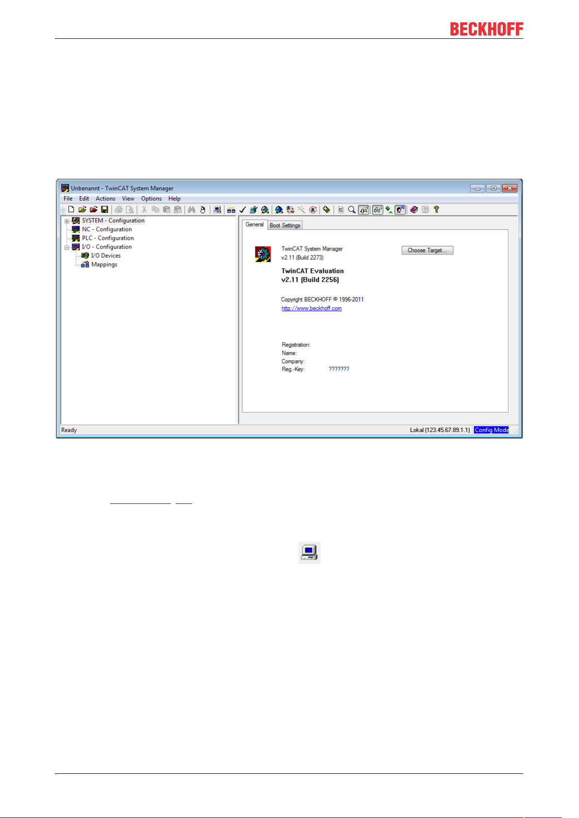
Commissioning
5.1.1 TwinCAT 2
Startup
TwinCAT basically uses two user interfaces: the TwinCAT System Manager for communication with the
electromechanical components and TwinCAT PLC Control for the development and compilation of a
controller. The starting point is the TwinCAT System Manager.
After successful installation of the TwinCAT system on the PC to be used for development, the TwinCAT2
System Manager displays the following user interface after startup:
Fig.46: Initial TwinCAT2 user interface
Generally, TwinCAT can be used in local or remote mode. Once the TwinCAT system including the user
interface (standard) is installed on the respective PLC, TwinCAT can be used in local mode and thereby the
next step is “Insert Device [}68]”.
If the intention is to address the TwinCAT runtime environment installed on a PLC as development
environment remotely from another system, the target system must be made known first. In the menu under
“Actions” → “Choose Target System...”, via the symbol “ ” or the “F8” key, open the following window:
EL511266 Version: 1.1
Page 67
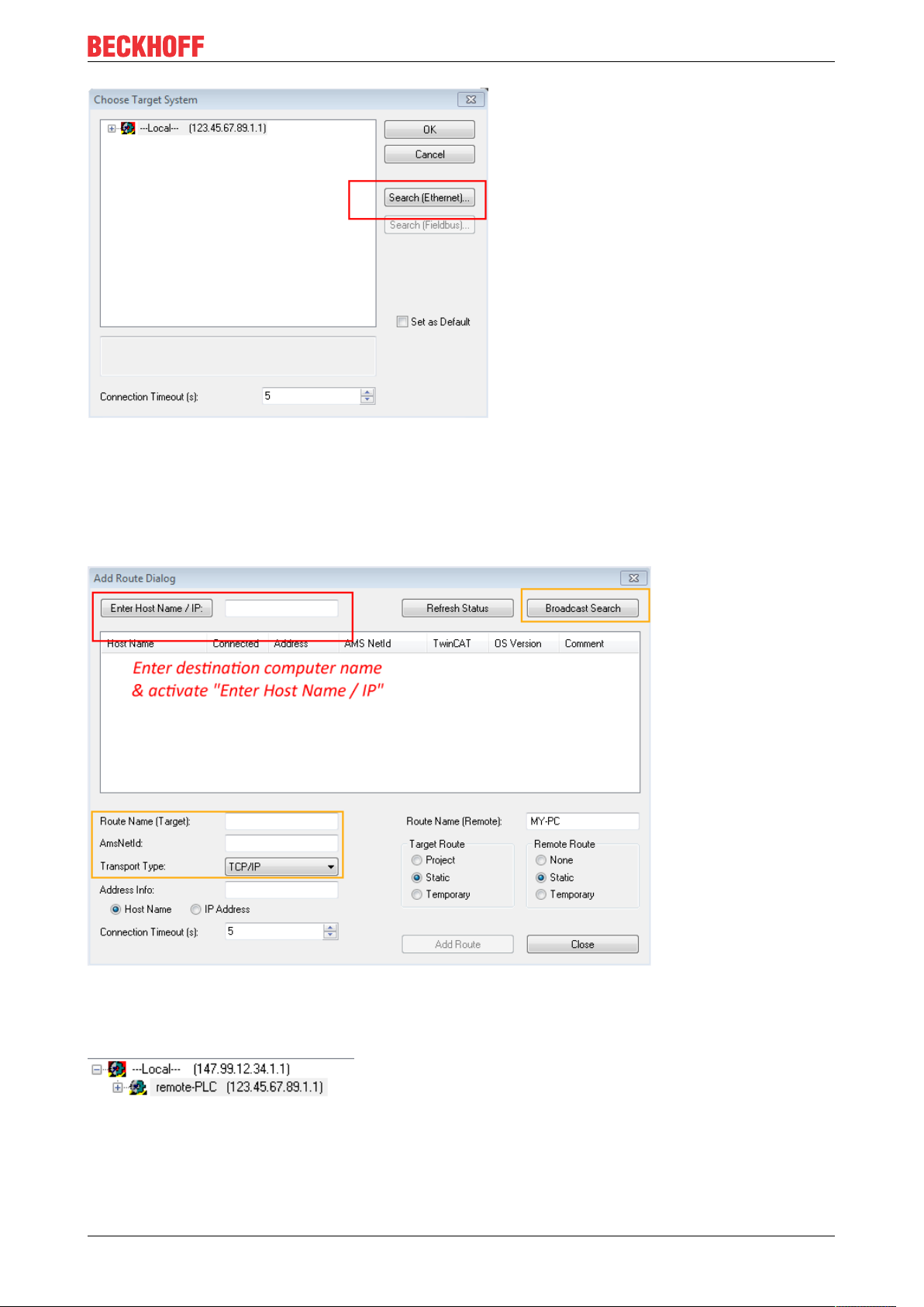
Fig.47: Selection of the target system
Use “Search (Ethernet)...” to enter the target system. Thus a next dialog opens to either:
Commissioning
• enter the known computer name after “Enter Host Name / IP:” (as shown in red)
• perform a “Broadcast Search” (if the exact computer name is not known)
• enter the known computer IP or AmsNetID.
Fig.48: Specify the PLC for access by the TwinCAT System Manager: selection of the target system
Once the target system has been entered, it is available for selection as follows (a password may have to be
entered):
After confirmation with “OK” the target system can be accessed via the System Manager.
EL5112 67Version: 1.1
Page 68
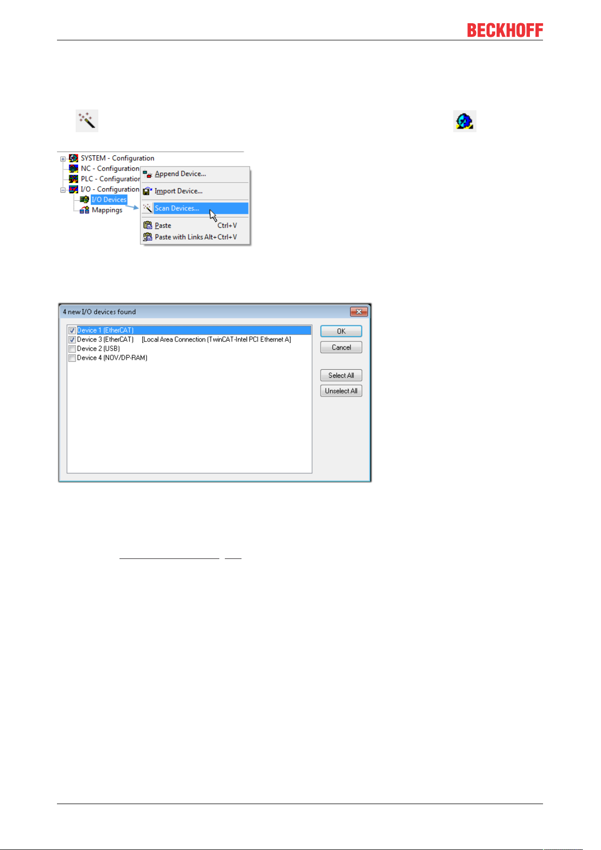
Commissioning
Adding devices
In the configuration tree of the TwinCAT2 System Manager user interface on the left, select “I/ODevices”
and then right-click to open a context menu and select “ScanDevices…”, or start the action in the menu bar
via . The TwinCAT System Manager may first have to be set to “Configmode” via or via menu
“Actions” → “Set/Reset TwinCAT to Config Mode…” (Shift + F4).
Fig.49: Select “Scan Devices...”
Confirm the warning message, which follows, and select “EtherCAT” in the dialog:
Fig.50: Automatic detection of I/O devices: selection the devices to be integrated
Confirm the message “Find new boxes”, in order to determine the terminals connected to the devices. “Free
Run” enables manipulation of input and output values in “Config mode” and should also be acknowledged.
Based on the sample configuration [}64] described at the beginning of this section, the result is as follows:
EL511268 Version: 1.1
Page 69
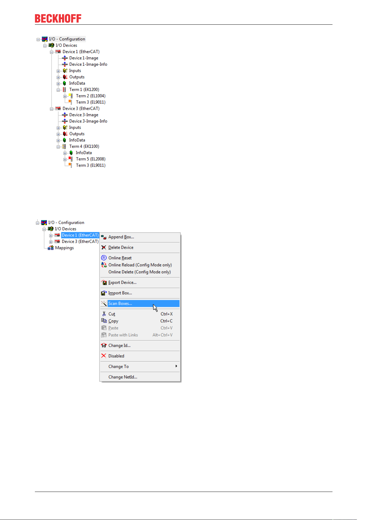
Commissioning
Fig.51: Mapping of the configuration in the TwinCAT2 System Manager
The whole process consists of two stages, which may be performed separately (first determine the devices,
then determine the connected elements such as boxes, terminals, etc.). A scan can also be initiated by
selecting “Device ...” from the context menu, which then reads the elements present in the configuration
below:
Fig.52: Reading of individual terminals connected to a device
This functionality is useful if the actual configuration is modified at short notice.
Programming and integrating the PLC
TwinCAT PLC Control is the development environment for the creation of the controller in different program
environments: TwinCAT PLC Control supports all languages described in IEC 61131-3. There are two textbased languages and three graphical languages.
• Text-based languages
◦ Instruction List (IL)
EL5112 69Version: 1.1
Page 70
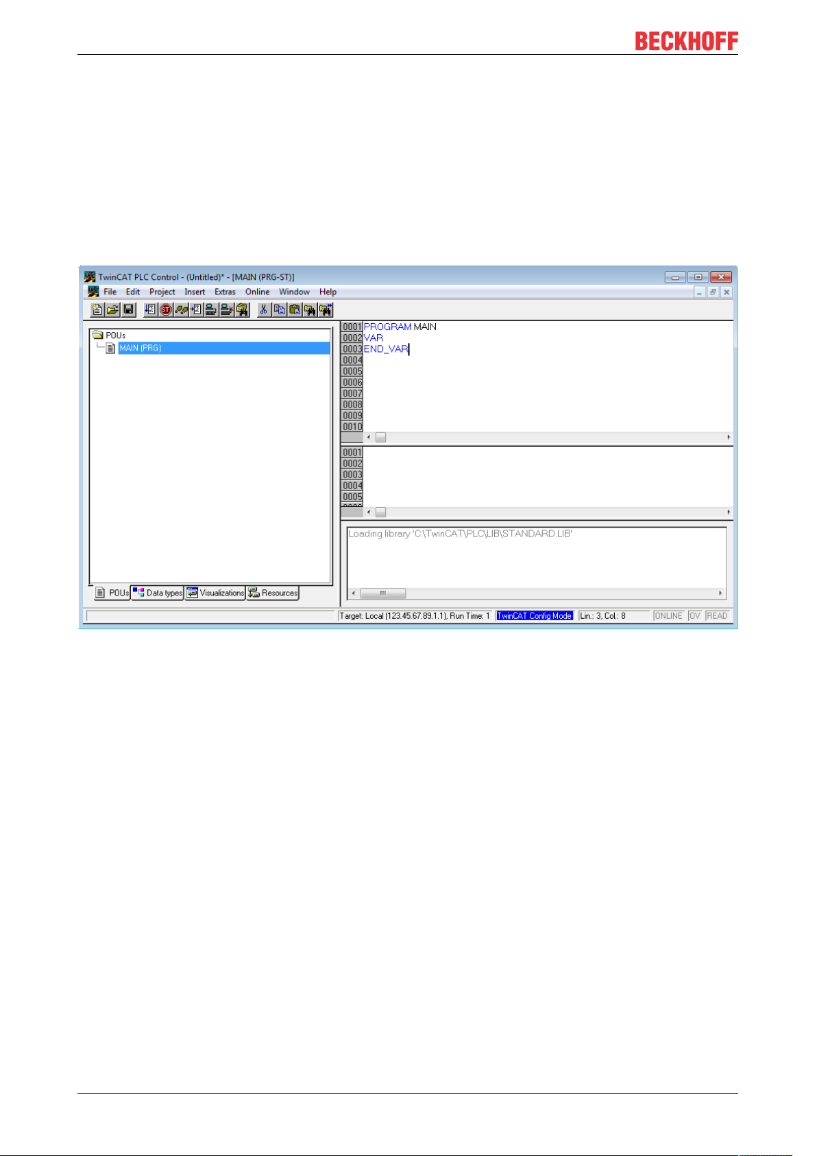
Commissioning
◦ Structured Text (ST)
• Graphical languages
◦ Function Block Diagram (FBD)
◦ Ladder Diagram (LD)
◦ The Continuous Function Chart Editor (CFC)
◦ Sequential Function Chart (SFC)
The following section refers to Structured Text (ST).
After starting TwinCAT PLC Control, the following user interface is shown for an initial project:
Fig.53: TwinCAT PLC Control after startup
Sample variables and a sample program have been created and stored under the name “PLC_example.pro”:
EL511270 Version: 1.1
Page 71
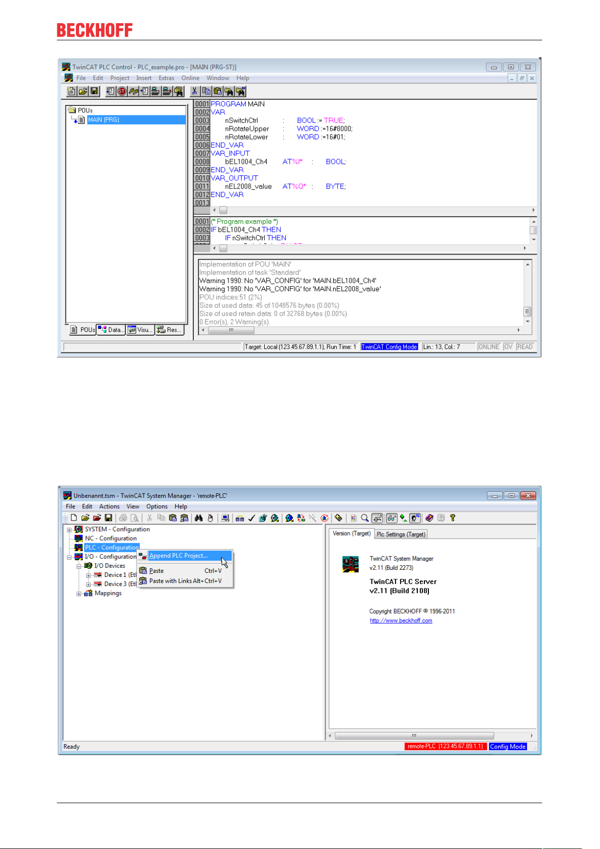
Commissioning
Fig.54: Sample program with variables after a compile process (without variable integration)
Warning 1990 (missing “VAR_CONFIG”) after a compile process indicates that the variables defined as
external (with the ID “AT%I*” or “AT%Q*”) have not been assigned. After successful compilation, TwinCAT
PLC Control creates a “*.tpy” file in the directory in which the project was stored. This file (“*.tpy”) contains
variable assignments and is not known to the System Manager, hence the warning. Once the System
Manager has been notified, the warning no longer appears.
First, integrate the TwinCAT PLC Control project in the System Manager via the context menu of the PLC
configuration; right-click and select “Append PLC Project…”:
Fig.55: Appending the TwinCAT PLC Control project
EL5112 71Version: 1.1
Page 72
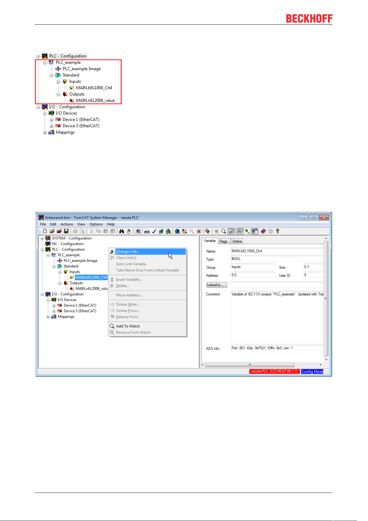
Commissioning
Select the PLC configuration “PLC_example.tpy” in the browser window that opens. The project including the
two variables identified with “AT” are then integrated in the configuration tree of the System Manager:
Fig.56: PLC project integrated in the PLC configuration of the System Manager
The two variables “bEL1004_Ch4” and “nEL2008_value” can now be assigned to certain process objects of
the I/O configuration.
Assigning variables
Open a window for selecting a suitable process object (PDO) via the context menu of a variable of the
integrated project “PLC_example” and via “Modify Link...” “Standard”:
Fig.57: Creating the links between PLC variables and process objects
In the window that opens, the process object for the variable “bEL1004_Ch4” of type BOOL can be selected
from the PLC configuration tree:
EL511272 Version: 1.1
Page 73
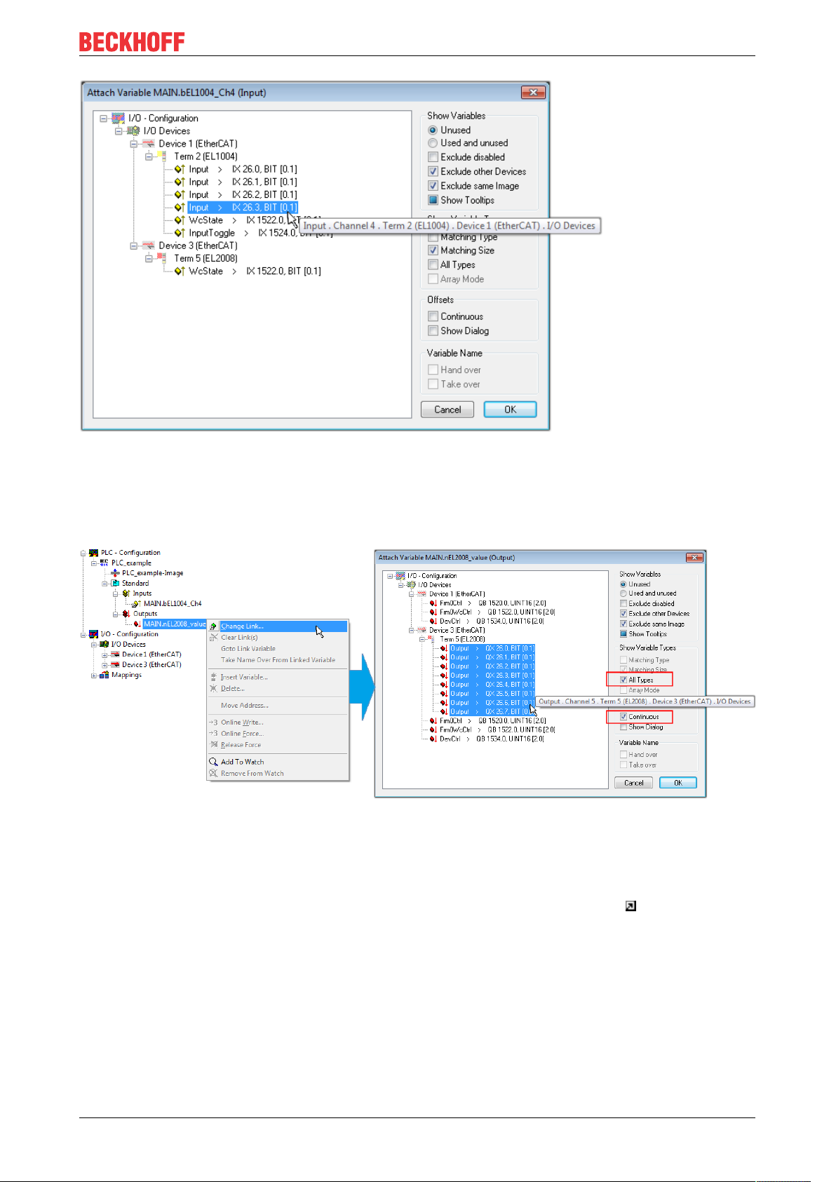
Commissioning
Fig.58: Selecting PDO of type BOOL
According to the default setting, certain PDO objects are now available for selection. In this sample the input
of channel 4 of the EL1004 terminal is selected for linking. In contrast, the checkbox “All types” must be
ticked for creating the link for the output variables, in order to allocate a set of eight separate output bits to a
byte variable. The following diagram shows the whole process:
Fig.59: Selecting several PDOs simultaneously: activate “Continuous” and “All types”
Note that the “Continuous” checkbox was also activated. This is designed to allocate the bits contained in the
byte of the variable “nEL2008_value” sequentially to all eight selected output bits of the EL2008 terminal. In
this way it is possible to subsequently address all eight outputs of the terminal in the program with a byte
corresponding to bit 0 for channel 1 to bit 7 for channel 8 of the PLC. A special symbol ( ) at the yellow or
red object of the variable indicates that a link exists. The links can also be checked by selecting a “Goto Link
Variable” from the context menu of a variable. The object opposite, in this case the PDO, is automatically
selected:
EL5112 73Version: 1.1
Page 74

Commissioning
Fig.60: Application of a “Goto Link” variable, using “MAIN.bEL1004_Ch4” as a sample
The process of assigning variables to the PDO is completed via the menu selection “Actions” → “Generate
Mappings”, key Ctrl+M or by clicking on the symbol in the menu.
This can be visualized in the configuration:
The process of creating links can also take place in the opposite direction, i.e. starting with individual PDOs
to variable. However, in this example it would then not be possible to select all output bits for the EL2008,
since the terminal only makes individual digital outputs available. If a terminal has a byte, word, integer or
similar PDO, it is possible to allocate this a set of bit-standardized variables (type “BOOL”). Here, too, a
“Goto Link Variable” from the context menu of a PDO can be executed in the other direction, so that the
respective PLC instance can then be selected.
Activation of the configuration
The allocation of PDO to PLC variables has now established the connection from the controller to the inputs
and outputs of the terminals. The configuration can now be activated. First, the configuration can be verified
via (or via “Actions” → “Check Configuration”). If no error is present, the configuration can be
activated via (or via “Actions” → “Activate Configuration…”) to transfer the System Manager settings
to the runtime system. Confirm the messages “Old configurations are overwritten!” and “Restart TwinCAT
system in Run mode” with “OK”.
A few seconds later the real-time status is displayed at the bottom right in the System Manager.
The PLC system can then be started as described below.
Starting the controller
Starting from a remote system, the PLC control has to be linked with the Embedded PC over Ethernet via
“Online” → “Choose Run-Time System…”:
EL511274 Version: 1.1
Page 75

Commissioning
Fig.61: Choose target system (remote)
In this sample “Runtime system 1 (port 801)” is selected and confirmed. Link the PLC with the real-time
system via menu option “Online” → “Login”, the F11 key or by clicking on the symbol .The control
program can then be loaded for execution. This results in the message “No program on the controller!
Should the new program be loaded?”, which should be acknowledged with “Yes”. The runtime environment
is ready for the program start:
EL5112 75Version: 1.1
Page 76

Commissioning
Fig.62: PLC Control logged in, ready for program startup
The PLC can now be started via “Online” → “Run”, F5 key or .
5.1.2 TwinCAT 3
Startup
TwinCAT makes the development environment areas available together with Microsoft Visual Studio: after
startup, the project folder explorer appears on the left in the general window area (cf. “TwinCAT System
Manager” of TwinCAT2) for communication with the electromechanical components.
After successful installation of the TwinCAT system on the PC to be used for development, TwinCAT3
(shell) displays the following user interface after startup:
EL511276 Version: 1.1
Page 77

Commissioning
Fig.63: Initial TwinCAT3 user interface
First create a new project via (or under “File”→“New”→ “Project…”). In the
following dialog make the corresponding entries as required (as shown in the diagram):
Fig.64: Create new TwinCAT project
The new project is then available in the project folder explorer:
EL5112 77Version: 1.1
Page 78

Commissioning
Fig.65: New TwinCAT3 project in the project folder explorer
Generally, TwinCAT can be used in local or remote mode. Once the TwinCAT system including the user
interface (standard) is installed on the respective PLC, TwinCAT can be used in local mode and thereby the
next step is “Insert Device [}79]”.
If the intention is to address the TwinCAT runtime environment installed on a PLC as development
environment remotely from another system, the target system must be made known first. Via the symbol in
the menu bar:
expand the pull-down menu:
and open the following window:
Fig.66: Selection dialog: Choose the target system
EL511278 Version: 1.1
Page 79

Use “Search (Ethernet)...” to enter the target system. Thus a next dialog opens to either:
• enter the known computer name after “Enter Host Name / IP:” (as shown in red)
• perform a “Broadcast Search” (if the exact computer name is not known)
• enter the known computer IP or AmsNetID.
Commissioning
Fig.67: Specify the PLC for access by the TwinCAT System Manager: selection of the target system
Once the target system has been entered, it is available for selection as follows (a password may have to be
entered):
After confirmation with “OK” the target system can be accessed via the Visual Studio shell.
Adding devices
In the project folder explorer of the Visual Studio shell user interface on the left, select “Devices” within
element “I/O”, then right-click to open a context menu and select “Scan” or start the action via in the
menu bar. The TwinCAT System Manager may first have to be set to “Config mode” via or via the
menu “TwinCAT” → “Restart TwinCAT (Config mode)”.
Fig.68: Select “Scan”
Confirm the warning message, which follows, and select “EtherCAT” in the dialog:
EL5112 79Version: 1.1
Page 80
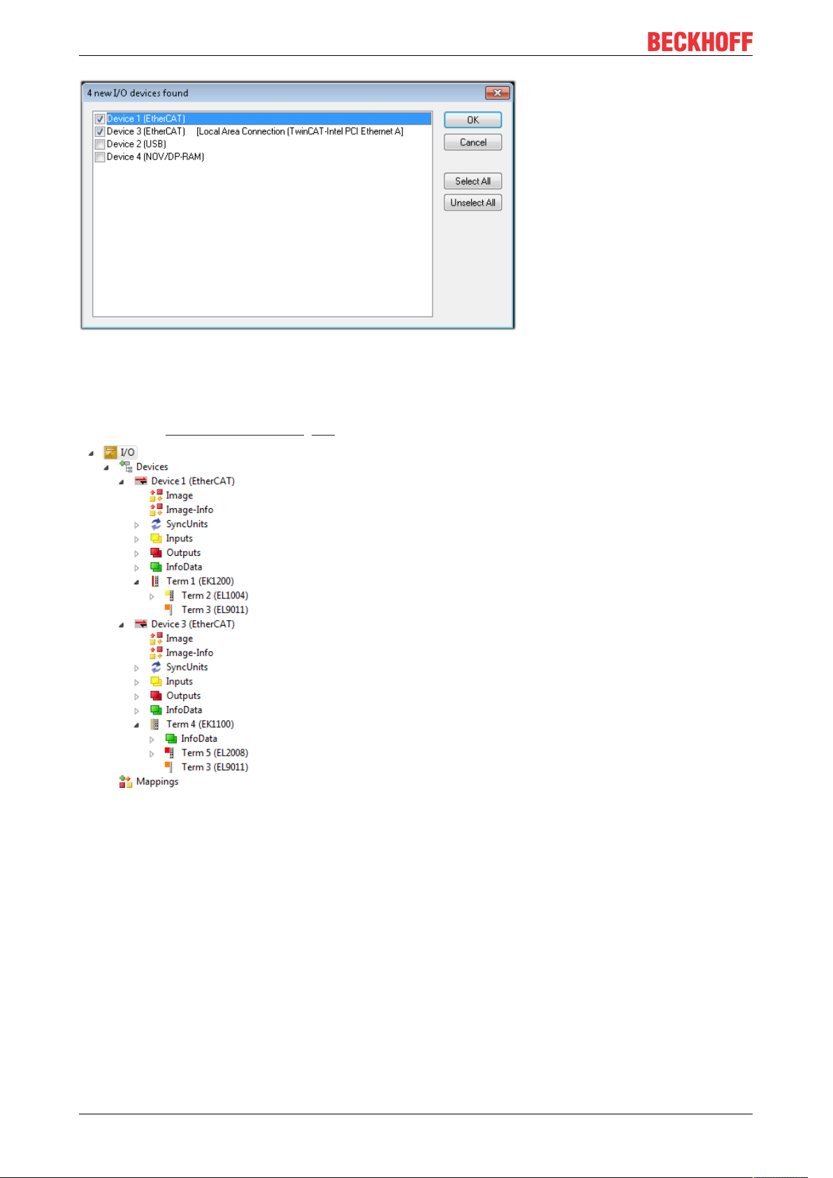
Commissioning
Fig.69: Automatic detection of I/O devices: selection the devices to be integrated
Confirm the message “Find new boxes”, in order to determine the terminals connected to the devices. “Free
Run” enables manipulation of input and output values in “Config mode” and should also be acknowledged.
Based on the sample configuration [}64] described at the beginning of this section, the result is as follows:
Fig.70: Mapping of the configuration in VS shell of the TwinCAT3 environment
The whole process consists of two stages, which may be performed separately (first determine the devices,
then determine the connected elements such as boxes, terminals, etc.). A scan can also be initiated by
selecting “Device ...” from the context menu, which then reads the elements present in the configuration
below:
EL511280 Version: 1.1
Page 81
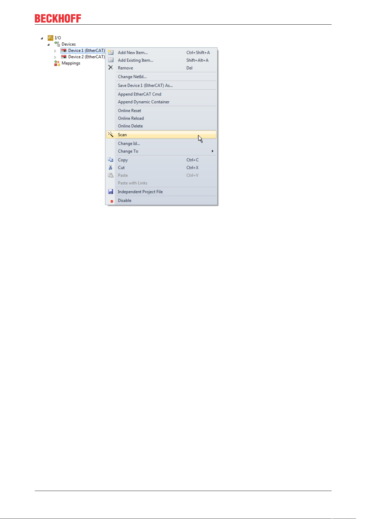
Commissioning
Fig.71: Reading of individual terminals connected to a device
This functionality is useful if the actual configuration is modified at short notice.
Programming the PLC
TwinCAT PLC Control is the development environment for the creation of the controller in different program
environments: TwinCAT PLC Control supports all languages described in IEC 61131-3. There are two textbased languages and three graphical languages.
• Text-based languages
◦ Instruction List (IL)
◦ Structured Text (ST)
• Graphical languages
◦ Function Block Diagram (FBD)
◦ Ladder Diagram (LD)
◦ The Continuous Function Chart Editor (CFC)
◦ Sequential Function Chart (SFC)
The following section refers to Structured Text (ST).
In order to create a programming environment, a PLC subproject is added to the project sample via the
context menu of “PLC” in the project folder explorer by selecting “Add New Item….”:
EL5112 81Version: 1.1
Page 82
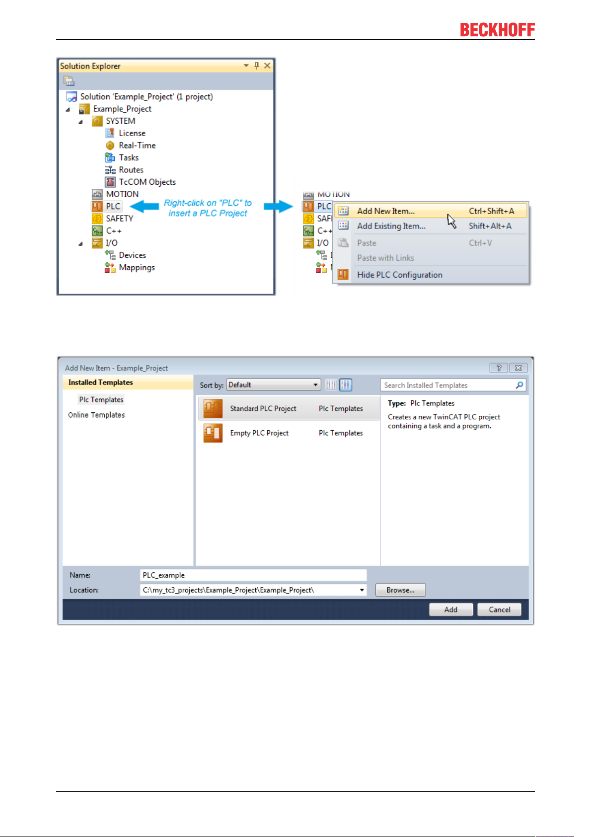
Commissioning
Fig.72: Adding the programming environment in “PLC”
In the dialog that opens select “Standard PLC project” and enter “PLC_example” as project name, for
example, and select a corresponding directory:
Fig.73: Specifying the name and directory for the PLC programming environment
The “Main” program, which already exists by selecting “Standard PLC project”, can be opened by doubleclicking on “PLC_example_project” in “POUs”. The following user interface is shown for an initial project:
EL511282 Version: 1.1
Page 83
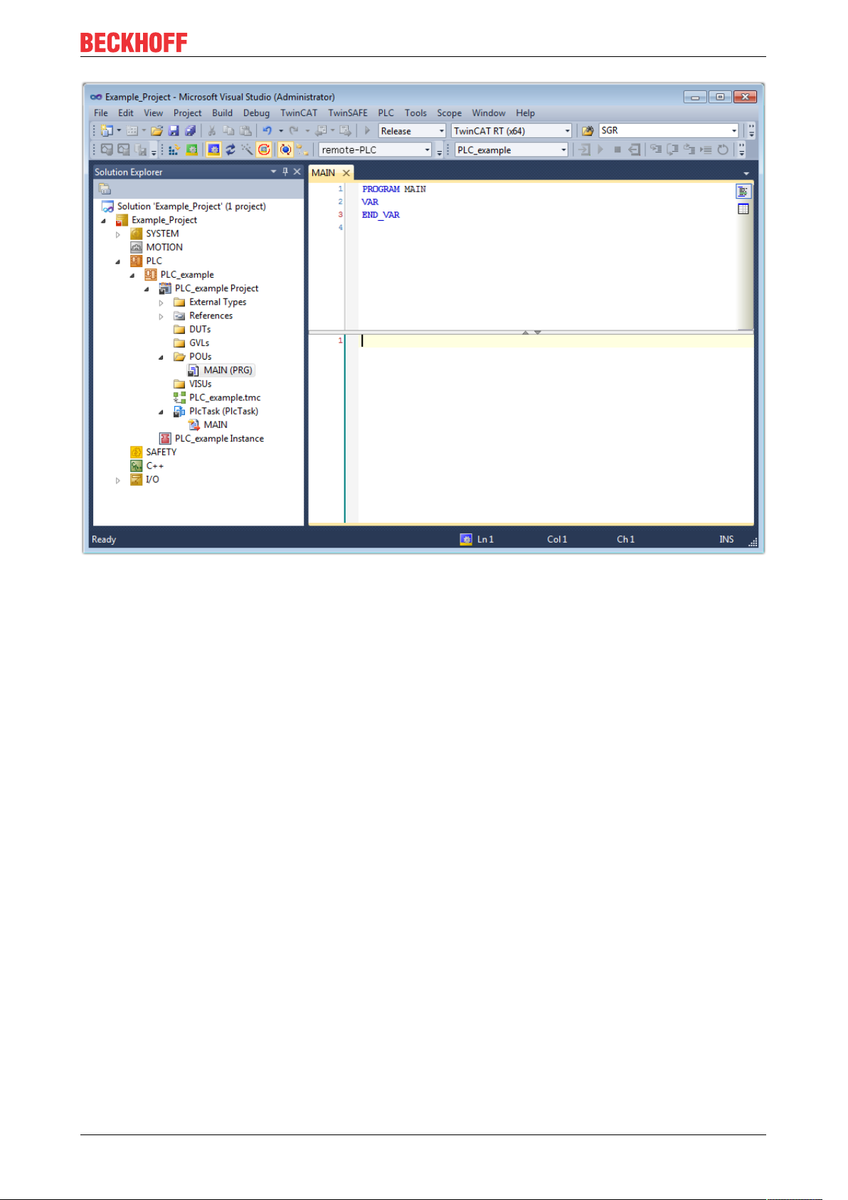
Commissioning
Fig.74: Initial “Main” program of the standard PLC project
To continue, sample variables and a sample program have now been created:
EL5112 83Version: 1.1
Page 84
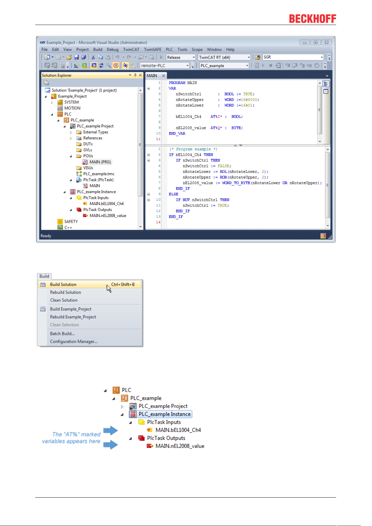
Commissioning
Fig.75: Sample program with variables after a compile process (without variable integration)
The control program is now created as a project folder, followed by the compile process:
Fig.76: Start program compilation
The following variables, identified in the ST/ PLC program with “AT%”, are then available in under
“Assignments” in the project folder explorer:
Assigning variables
Via the menu of an instance - variables in the “PLC” context, use the “Modify Link…” option to open a
window for selecting a suitable process object (PDO) for linking:
EL511284 Version: 1.1
Page 85
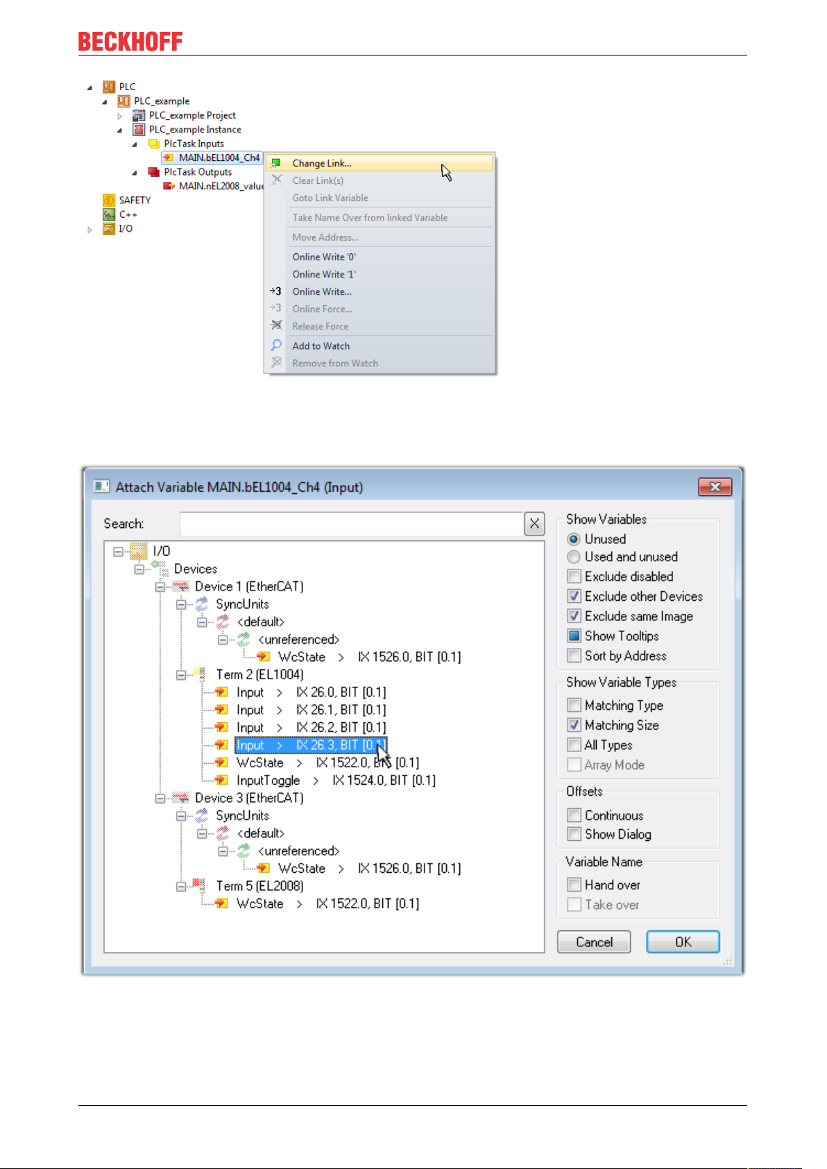
Commissioning
Fig.77: Creating the links between PLC variables and process objects
In the window that opens, the process object for the variable “bEL1004_Ch4” of type BOOL can be selected
from the PLC configuration tree:
Fig.78: Selecting PDO of type BOOL
According to the default setting, certain PDO objects are now available for selection. In this sample the input
of channel 4 of the EL1004 terminal is selected for linking. In contrast, the checkbox “All types” must be
ticked for creating the link for the output variables, in order to allocate a set of eight separate output bits to a
byte variable. The following diagram shows the whole process:
EL5112 85Version: 1.1
Page 86
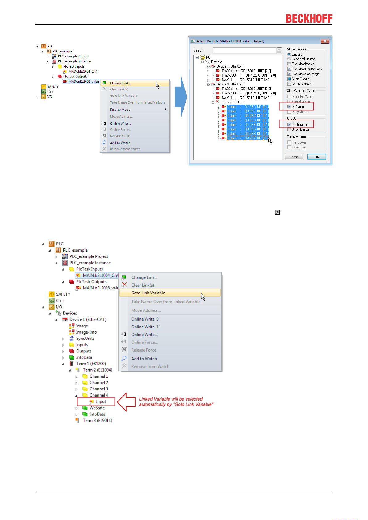
Commissioning
Fig.79: Selecting several PDOs simultaneously: activate “Continuous” and “All types”
Note that the “Continuous” checkbox was also activated. This is designed to allocate the bits contained in the
byte of the variable “nEL2008_value” sequentially to all eight selected output bits of the EL2008 terminal. In
this way it is possible to subsequently address all eight outputs of the terminal in the program with a byte
corresponding to bit 0 for channel 1 to bit 7 for channel 8 of the PLC. A special symbol ( ) at the yellow or
red object of the variable indicates that a link exists. The links can also be checked by selecting a “Goto Link
Variable” from the context menu of a variable. The object opposite, in this case the PDO, is automatically
selected:
Fig.80: Application of a “Goto Link” variable, using “MAIN.bEL1004_Ch4” as a sample
The process of creating links can also take place in the opposite direction, i.e. starting with individual PDOs
to variable. However, in this example it would then not be possible to select all output bits for the EL2008,
since the terminal only makes individual digital outputs available. If a terminal has a byte, word, integer or
EL511286 Version: 1.1
Page 87

Commissioning
similar PDO, it is possible to allocate this a set of bit-standardized variables (type “BOOL”). Here, too, a
“Goto Link Variable” from the context menu of a PDO can be executed in the other direction, so that the
respective PLC instance can then be selected.
Note on the type of variable assignment
The following type of variable assignment can only be used from TwinCAT version V3.1.4024.4 onwards and is only available for terminals with a microcontroller.
In TwinCAT it is possible to create a structure from the mapped process data of a terminal. An instance of
this structure can then be created in the PLC, so it is possible to access the process data directly from the
PLC without having to declare own variables.
The procedure for the EL3001 1-channel analog input terminal -10...+10V is shown as an example.
1. First the required process data must be selected in the “Process data” tab in TwinCAT.
2. After that, the PLC data type must be generated in the tab “PLC” via the check box.
3. The data type in the “Data Type” field can then be copied using the “Copy” button.
Fig.81: Creating a PLC data type
4. An instance of the data structure of the copied data type must then be created in the PLC.
Fig.82: Instance_of_struct
5. Then the project folder must be created. This can be done either via the key combination “CTRL +
Shift + B” or via the “Build” tab in TwinCAT.
6. The structure in the “PLC” tab of the terminal must then be linked to the created instance.
EL5112 87Version: 1.1
Page 88

Commissioning
Fig.83: Linking the structure
7. In the PLC the process data can then be read or written via the structure in the program code.
Fig.84: Reading a variable from the structure of the process data
Activation of the configuration
The allocation of PDO to PLC variables has now established the connection from the controller to the inputs
and outputs of the terminals. The configuration can now be activated with or via the menu under
“TwinCAT” in order to transfer settings of the development environment to the runtime system. Confirm the
messages “Old configurations are overwritten!” and “Restart TwinCAT system in Run mode” with “OK”. The
corresponding assignments can be seen in the project folder explorer:
A few seconds later the corresponding status of the Run mode is displayed in the form of a rotating symbol
at the bottom right of the VS shell development environment. The PLC system can then be started as
described below.
EL511288 Version: 1.1
Page 89
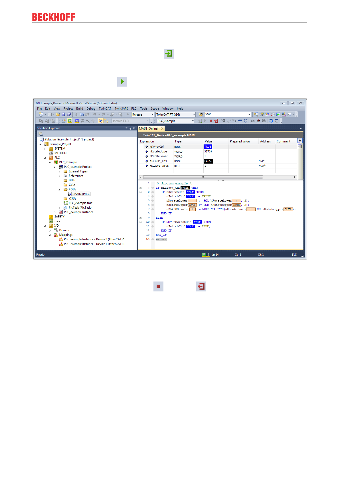
Commissioning
Starting the controller
Select the menu option “PLC” → “Login” or click on to link the PLC with the real-time system and load
the control program for execution. This results in the message No program on the controller! Should the new
program be loaded?, which should be acknowledged with “Yes”. The runtime environment is ready for
program start by click on symbol , the “F5” key or via “PLC” in the menu selecting “Start”. The started
programming environment shows the runtime values of individual variables:
Fig.85: TwinCAT development environment (VS shell): logged-in, after program startup
The two operator control elements for stopping and logout result in the required action
(accordingly also for stop “Shift + F5”, or both actions can be selected via the PLC menu).
5.2 TwinCAT Development Environment
The Software for automation TwinCAT (The Windows Control and Automation Technology) will be
distinguished into:
• TwinCAT2: System Manager (Configuration) & PLC Control (Programming)
• TwinCAT3: Enhancement of TwinCAT2 (Programming and Configuration takes place via a common
Development Environment)
Details:
• TwinCAT2:
◦ Connects I/O devices to tasks in a variable-oriented manner
◦ Connects tasks to tasks in a variable-oriented manner
◦ Supports units at the bit level
◦ Supports synchronous or asynchronous relationships
◦ Exchange of consistent data areas and process images
◦ Datalink on NT - Programs by open Microsoft Standards (OLE, OCX, ActiveX, DCOM+, etc.)
EL5112 89Version: 1.1
Page 90

Commissioning
◦ Integration of IEC 61131-3-Software-SPS, Software- NC and Software-CNC within Windows
NT/2000/XP/Vista, Windows 7, NT/XP Embedded, CE
◦ Interconnection to all common fieldbusses
◦ More…
Additional features:
• TwinCAT3 (eXtended Automation):
◦ Visual-Studio®-Integration
◦ Choice of the programming language
◦ Supports object orientated extension of IEC 61131-3
◦ Usage of C/C++ as programming language for real time applications
◦ Connection to MATLAB®/Simulink®
◦ Open interface for expandability
◦ Flexible run-time environment
◦ Active support of Multi-Core- und 64-Bit-Operatingsystem
◦ Automatic code generation and project creation with the TwinCAT Automation Interface
◦ More…
Within the following sections commissioning of the TwinCAT Development Environment on a PC System for
the control and also the basically functions of unique control elements will be explained.
Please see further information to TwinCAT2 and TwinCAT3 at http://infosys.beckhoff.com.
5.2.1 Installation of the TwinCAT real-time driver
In order to assign real-time capability to a standard Ethernet port of an IPC controller, the Beckhoff real-time
driver has to be installed on this port under Windows.
This can be done in several ways. One option is described here.
In the System Manager call up the TwinCAT overview of the local network interfaces via Options → Show
Real Time Ethernet Compatible Devices.
Fig.86: System Manager “Options” (TwinCAT2)
This have to be called up by the Menü “TwinCAT” within the TwinCAT3 environment:
Fig.87: Call up under VS Shell (TwinCAT3)
EL511290 Version: 1.1
Page 91
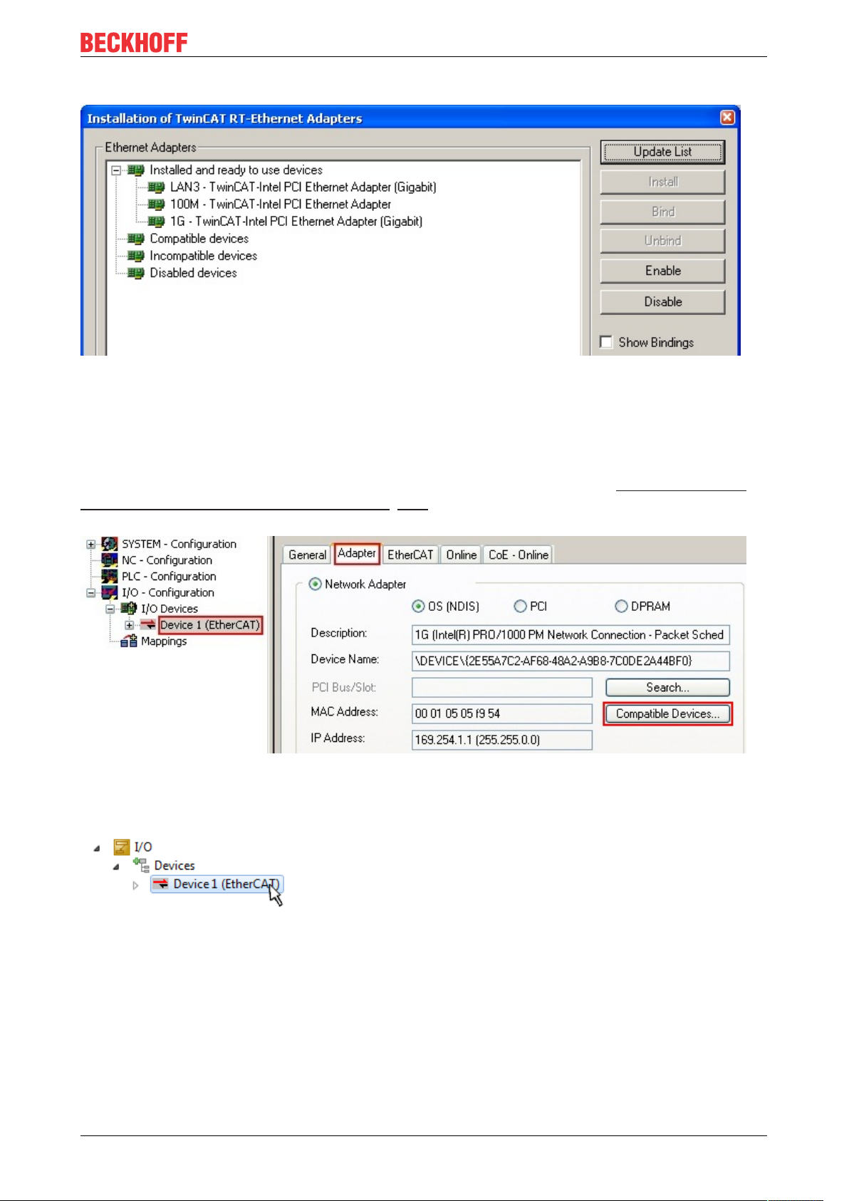
Commissioning
The following dialog appears:
Fig.88: Overview of network interfaces
Interfaces listed under “Compatible devices” can be assigned a driver via the “Install” button. A driver should
only be installed on compatible devices.
A Windows warning regarding the unsigned driver can be ignored.
Alternatively an EtherCAT-device can be inserted first of all as described in chapter Offline configuration
creation, section “Creating the EtherCAT device” [}100] in order to view the compatible ethernet ports via its
EtherCAT properties (tab “Adapter”, button “Compatible Devices…”):
Fig.89: EtherCAT device properties(TwinCAT2): click on “Compatible Devices…” of tab “Adapte””
TwinCAT 3: the properties of the EtherCAT device can be opened by double click on “Device .. (EtherCAT)”
within the Solution Explorer under “I/O”:
After the installation the driver appears activated in the Windows overview for the network interface
(Windows Start → System Properties → Network)
EL5112 91Version: 1.1
Page 92

Commissioning
Fig.90: Windows properties of the network interface
A correct setting of the driver could be:
Fig.91: Exemplary correct driver setting for the Ethernet port
Other possible settings have to be avoided:
EL511292 Version: 1.1
Page 93

Commissioning
Fig.92: Incorrect driver settings for the Ethernet port
EL5112 93Version: 1.1
Page 94

Commissioning
IP address of the port used
IP address/DHCP
In most cases an Ethernet port that is configured as an EtherCAT device will not transport general
IP packets. For this reason and in cases where an EL6601 or similar devices are used it is useful to
specify a fixed IP address for this port via the “Internet Protocol TCP/IP” driver setting and to disable
DHCP. In this way the delay associated with the DHCP client for the Ethernet port assigning itself a
default IP address in the absence of a DHCP server is avoided. A suitable address space is
192.168.x.x, for example.
Fig.93: TCP/IP setting for the Ethernet port
EL511294 Version: 1.1
Page 95

Commissioning
5.2.2 Notes regarding ESI device description
Installation of the latest ESI device description
The TwinCAT EtherCAT master/System Manager needs the device description files for the devices to be
used in order to generate the configuration in online or offline mode. The device descriptions are contained
in the so-called ESI files (EtherCAT Slave Information) in XML format. These files can be requested from the
respective manufacturer and are made available for download. An *.xml file may contain several device
descriptions.
The ESI files for Beckhoff EtherCAT devices are available on the Beckhoff website.
The ESI files should be stored in the TwinCAT installation directory.
Default settings:
• TwinCAT2: C:\TwinCAT\IO\EtherCAT
• TwinCAT3: C:\TwinCAT\3.1\Config\Io\EtherCAT
The files are read (once) when a new System Manager window is opened, if they have changed since the
last time the System Manager window was opened.
A TwinCAT installation includes the set of Beckhoff ESI files that was current at the time when the TwinCAT
build was created.
For TwinCAT2.11/TwinCAT3 and higher, the ESI directory can be updated from the System Manager, if the
programming PC is connected to the Internet; by
• TwinCAT2: Option → “Update EtherCAT Device Descriptions”
• TwinCAT3: TwinCAT → EtherCAT Devices → “Update Device Descriptions (via ETG Website)…”
The TwinCAT ESI Updater [}99] is available for this purpose.
ESI
The *.xml files are associated with *.xsd files, which describe the structure of the ESI XML files. To
update the ESI device descriptions, both file types should therefore be updated.
Device differentiation
EtherCAT devices/slaves are distinguished by four properties, which determine the full device identifier. For
example, the device identifier EL2521-0025-1018 consists of:
• family key “EL”
• name “2521”
• type “0025”
• and revision “1018”
Fig.94: Identifier structure
The order identifier consisting of name + type (here: EL2521-0010) describes the device function. The
revision indicates the technical progress and is managed by Beckhoff. In principle, a device with a higher
revision can replace a device with a lower revision, unless specified otherwise, e.g. in the documentation.
Each revision has its own ESI description. See further notes.
EL5112 95Version: 1.1
Page 96
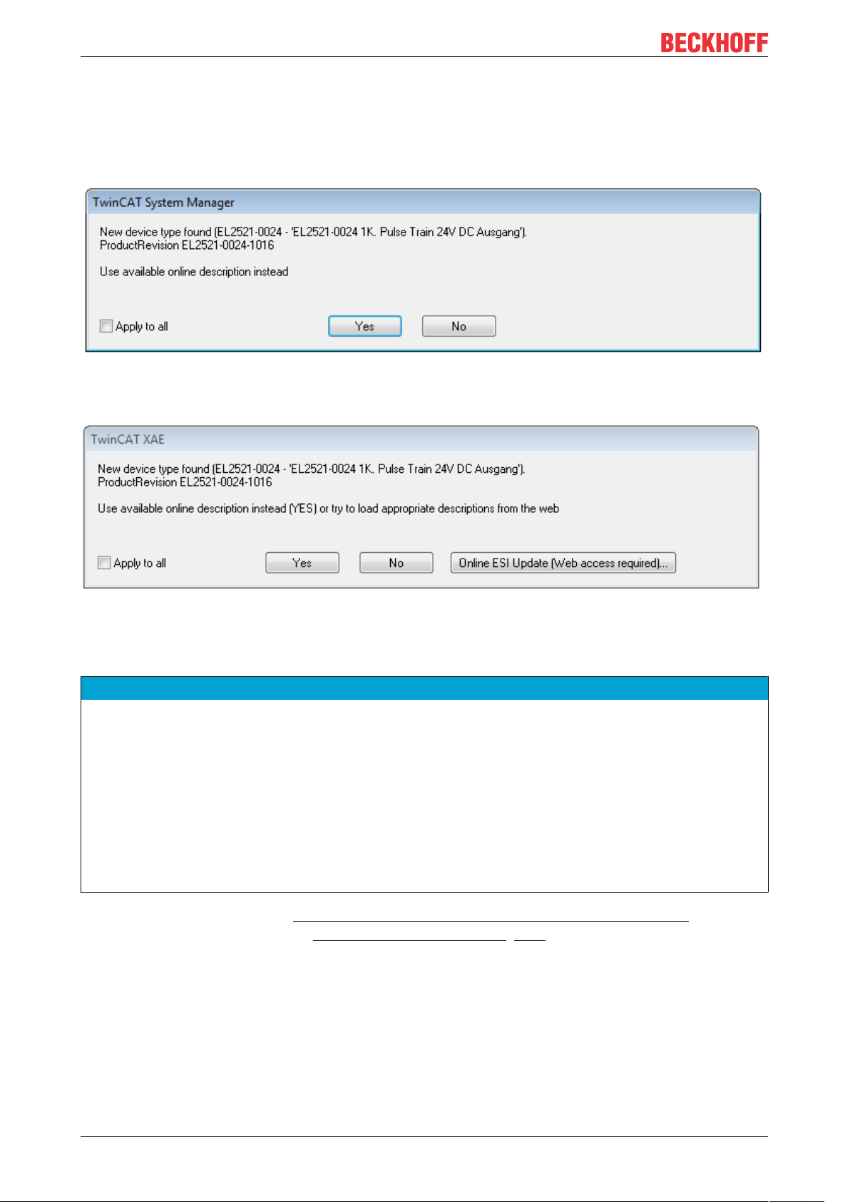
Commissioning
Online description
If the EtherCAT configuration is created online through scanning of real devices (see section Online setup)
and no ESI descriptions are available for a slave (specified by name and revision) that was found, the
System Manager asks whether the description stored in the device should be used. In any case, the System
Manager needs this information for setting up the cyclic and acyclic communication with the slave correctly.
Fig.95: OnlineDescription information window (TwinCAT2)
In TwinCAT3 a similar window appears, which also offers the Web update:
Fig.96: Information window OnlineDescription (TwinCAT3)
If possible, the Yes is to be rejected and the required ESI is to be requested from the device manufacturer.
After installation of the XML/XSD file the configuration process should be repeated.
NOTE
Changing the “usual” configuration through a scan
ü If a scan discovers a device that is not yet known to TwinCAT, distinction has to be made between two
cases. Taking the example here of the EL2521-0000 in the revision 1019
a) no ESI is present for the EL2521-0000 device at all, either for the revision 1019 or for an older revision.
The ESI must then be requested from the manufacturer (in this case Beckhoff).
b) an ESI is present for the EL2521-0000 device, but only in an older revision, e.g. 1018 or 1017.
In this case an in-house check should first be performed to determine whether the spare parts stock allows the integration of the increased revision into the configuration at all. A new/higher revision usually
also brings along new features. If these are not to be used, work can continue without reservations with
the previous revision 1018 in the configuration. This is also stated by the Beckhoff compatibility rule.
Refer in particular to the chapter “General notes on the use of Beckhoff EtherCAT IO components” and for
manual configuration to the chapter “Offline configuration creation [}100]”.
If the OnlineDescription is used regardless, the System Manager reads a copy of the device description from
the EEPROM in the EtherCAT slave. In complex slaves the size of the EEPROM may not be sufficient for the
complete ESI, in which case the ESI would be incomplete in the configurator. Therefore it’s recommended
using an offline ESI file with priority in such a case.
The System Manager creates for online recorded device descriptions a new file
“OnlineDescription0000...xml” in its ESI directory, which contains all ESI descriptions that were read online.
EL511296 Version: 1.1
Page 97
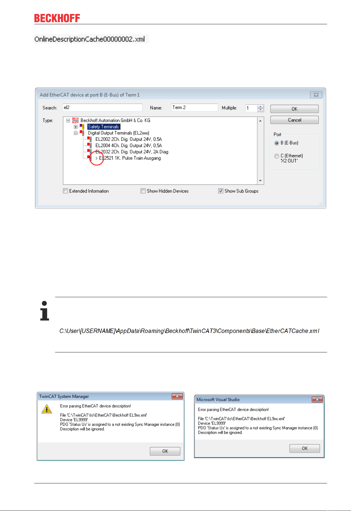
Commissioning
Fig.97: File OnlineDescription.xml created by the System Manager
Is a slave desired to be added manually to the configuration at a later stage, online created slaves are
indicated by a prepended symbol “>” in the selection list (see Figure Indication of an online recorded ESI of
EL2521 as an example).
Fig.98: Indication of an online recorded ESI of EL2521 as an example
If such ESI files are used and the manufacturer's files become available later, the file OnlineDescription.xml
should be deleted as follows:
• close all System Manager windows
• restart TwinCAT in Config mode
• delete “OnlineDescription0000...xml”
• restart TwinCAT System Manager
This file should not be visible after this procedure, if necessary press <F5> to update
OnlineDescription for TwinCAT3.x
In addition to the file described above “OnlineDescription0000...xml”, a so called EtherCAT cache
with new discovered devices is created by TwinCAT3.x, e.g. under Windows 7:
(Please note the language settings of the OS!)
You have to delete this file, too.
Faulty ESI file
If an ESI file is faulty and the System Manager is unable to read it, the System Manager brings up an
information window.
Fig.99: Information window for faulty ESI file (left: TwinCAT2; right: TwinCAT3)
EL5112 97Version: 1.1
Page 98

Commissioning
Reasons may include:
• Structure of the *.xml does not correspond to the associated *.xsd file → check your schematics
• Contents cannot be translated into a device description → contact the file manufacturer
EL511298 Version: 1.1
Page 99
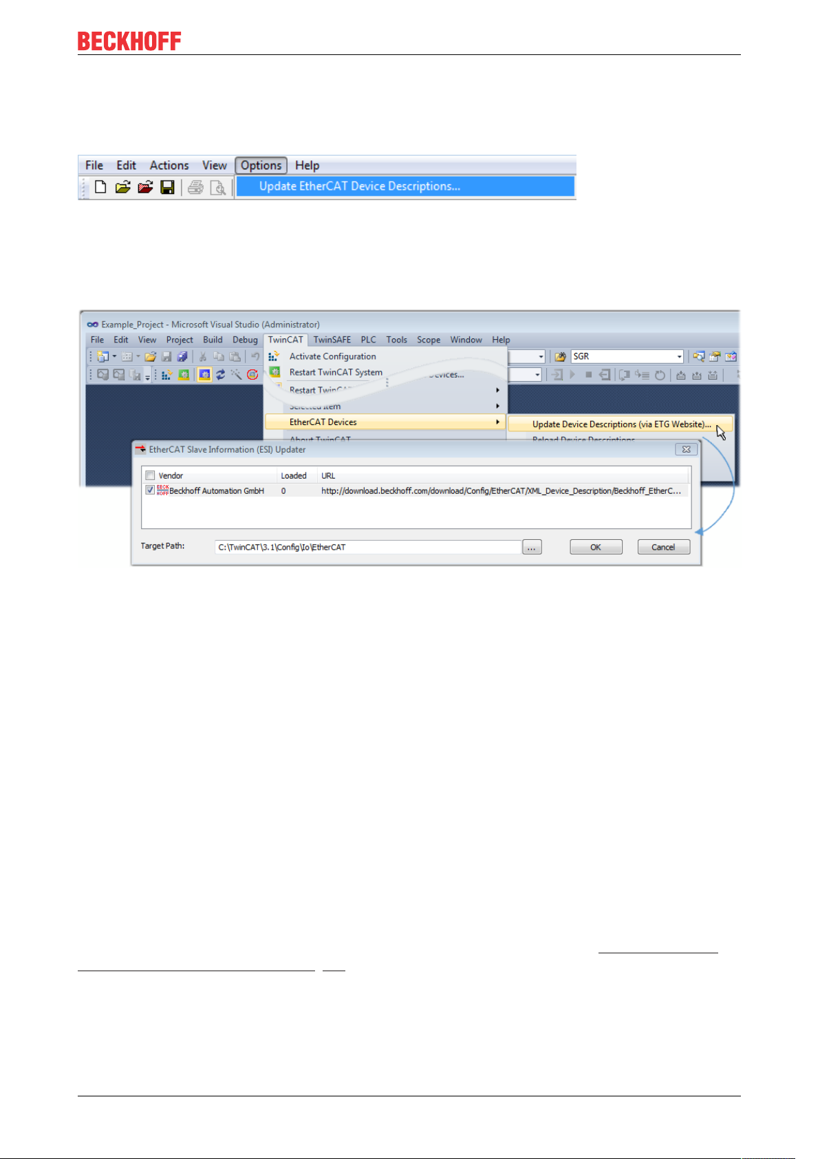
Commissioning
5.2.3 TwinCAT ESI Updater
For TwinCAT2.11 and higher, the System Manager can search for current Beckhoff ESI files automatically, if
an online connection is available:
Fig.100: Using the ESI Updater (>= TwinCAT2.11)
The call up takes place under:
“Options” → “Update EtherCAT Device Descriptions”
Selection under TwinCAT3:
Fig.101: Using the ESI Updater (TwinCAT3)
The ESI Updater (TwinCAT3) is a convenient option for automatic downloading of ESI data provided by
EtherCAT manufacturers via the Internet into the TwinCAT directory (ESI = EtherCAT slave information).
TwinCAT accesses the central ESI ULR directory list stored at ETG; the entries can then be viewed in the
Updater dialog, although they cannot be changed there.
The call up takes place under:
“TwinCAT” → “EtherCAT Devices” → “Update Device Description (via ETG Website)…”.
5.2.4 Distinction between Online and Offline
The distinction between online and offline refers to the presence of the actual I/O environment (drives,
terminals, EJ-modules). If the configuration is to be prepared in advance of the system configuration as a
programming system, e.g. on a laptop, this is only possible in “Offline configuration” mode. In this case all
components have to be entered manually in the configuration, e.g. based on the electrical design.
If the designed control system is already connected to the EtherCAT system and all components are
energised and the infrastructure is ready for operation, the TwinCAT configuration can simply be generated
through “scanning” from the runtime system. This is referred to as online configuration.
In any case, during each startup the EtherCAT master checks whether the slaves it finds match the
configuration. This test can be parameterised in the extended slave settings. Refer to note “Installation of
the latest ESI-XML device description” [}95].
For preparation of a configuration:
• the real EtherCAT hardware (devices, couplers, drives) must be present and installed
• the devices/modules must be connected via EtherCAT cables or in the terminal/ module strand in the
same way as they are intended to be used later
EL5112 99Version: 1.1
Page 100
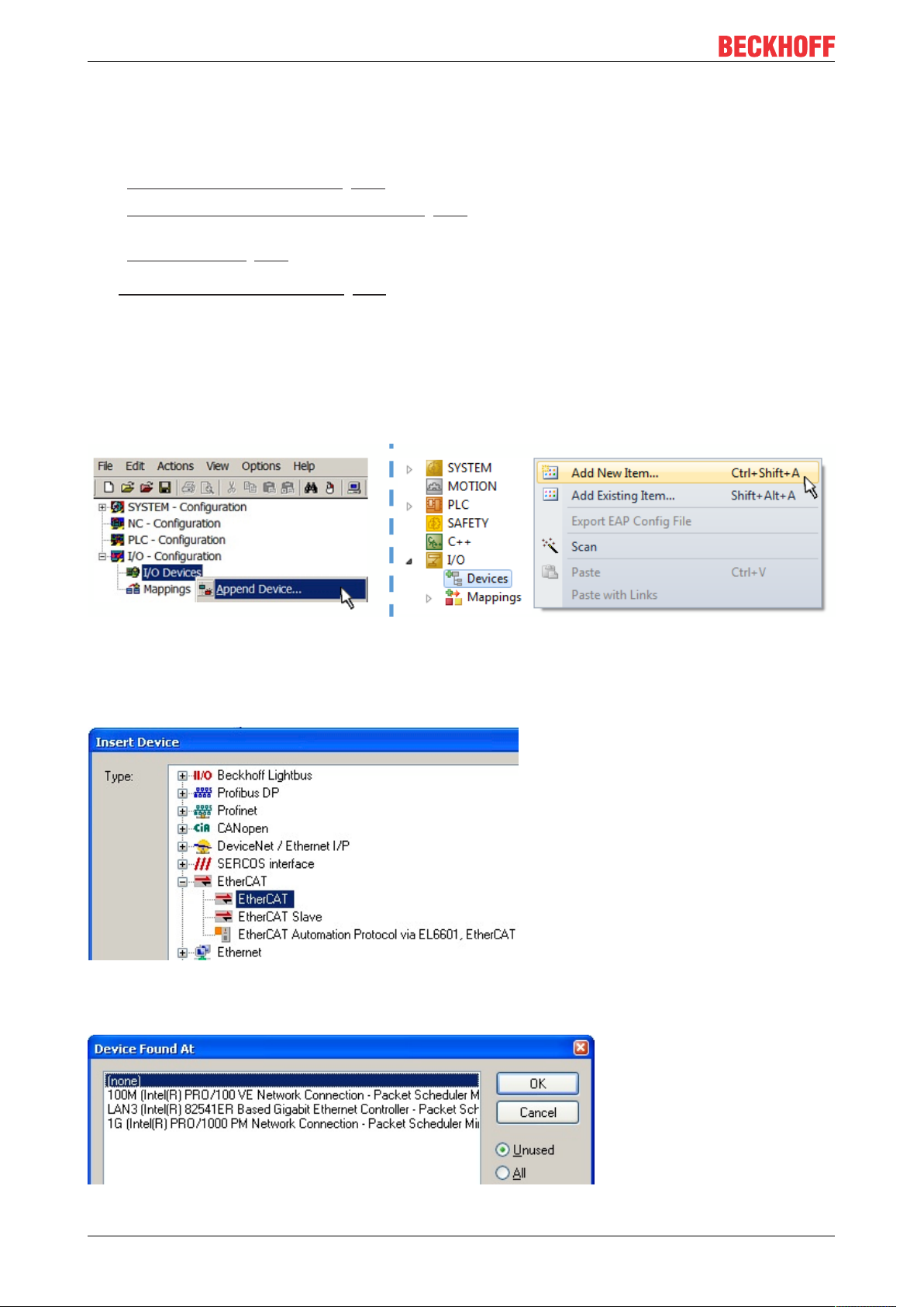
Commissioning
• the devices/modules be connected to the power supply and ready for communication
• TwinCAT must be in CONFIG mode on the target system.
The online scan process consists of:
• detecting the EtherCAT device [}105] (Ethernet port at the IPC)
• detecting the connected EtherCAT devices [}106]. This step can be carried out independent of the
preceding step
• troubleshooting [}109]
The scan with existing configuration [}110] can also be carried out for comparison.
5.2.5 OFFLINE configuration creation
Creating the EtherCAT device
Create an EtherCAT device in an empty System Manager window.
Fig.102: Append EtherCAT device (left: TwinCAT2; right: TwinCAT3)
Select type “EtherCAT” for an EtherCAT I/O application with EtherCAT slaves. For the present publisher/
subscriber service in combination with an EL6601/EL6614 terminal select “EtherCAT Automation Protocol
via EL6601”.
Fig.103: Selecting the EtherCAT connection (TwinCAT2.11, TwinCAT3)
Then assign a real Ethernet port to this virtual device in the runtime system.
Fig.104: Selecting the Ethernet port
EL5112100 Version: 1.1
 Loading...