

Page 1
Documentation
EL5042
2 Channel BiSS-C Interface
Version:
Date:
1.5
2020-03-31
Page 2

Page 3

Table of contents
Table of contents
1 Foreword ....................................................................................................................................................5
1.1 Notes on the documentation..............................................................................................................5
1.2 Safety instructions .............................................................................................................................6
1.3 Documentation issue status ..............................................................................................................7
1.4 Version identification of EtherCAT devices .......................................................................................7
1.4.1 Beckhoff Identification Code (BIC)................................................................................... 10
2 Product overview.....................................................................................................................................12
2.1 Introduction......................................................................................................................................12
2.2 Technical data .................................................................................................................................13
2.3 Basics of BiSS-C technology...........................................................................................................13
2.4 Start .................................................................................................................................................15
3 Basics communication ...........................................................................................................................16
3.1 EtherCAT basics..............................................................................................................................16
3.2 EtherCAT cabling – wire-bound.......................................................................................................16
3.3 General notes for setting the watchdog...........................................................................................17
3.4 EtherCAT State Machine.................................................................................................................19
3.5 CoE Interface...................................................................................................................................21
3.6 Distributed Clock .............................................................................................................................26
4 Mounting and wiring................................................................................................................................27
4.1 Instructions for ESD protection........................................................................................................27
4.2 Installation on mounting rails ...........................................................................................................27
4.3 Installation instructions for enhanced mechanical load capacity .....................................................31
4.4 Connection ......................................................................................................................................31
4.4.1 Connection system .......................................................................................................... 31
4.4.2 Wiring............................................................................................................................... 34
4.4.3 Shielding .......................................................................................................................... 35
4.5 Installation positions ........................................................................................................................35
4.6 Positioning of passive Terminals .....................................................................................................38
4.7 LEDs and connection ......................................................................................................................39
5 Commissioning........................................................................................................................................41
5.1 Quick start........................................................................................................................................41
5.2 TwinCAT Development Environment ..............................................................................................41
5.2.1 Installation of the TwinCAT real-time driver..................................................................... 42
5.2.2 Notes regarding ESI device description........................................................................... 47
5.2.3 TwinCAT ESI Updater ..................................................................................................... 51
5.2.4 Distinction between Online and Offline............................................................................ 51
5.2.5 OFFLINE configuration creation ...................................................................................... 52
5.2.6 ONLINE configuration creation ........................................................................................ 57
5.2.7 EtherCAT subscriber configuration.................................................................................. 65
5.3 General Notes - EtherCAT Slave Application..................................................................................74
5.4 Process data & parameter setting ...................................................................................................83
5.4.1 Sync Manager (SM)......................................................................................................... 83
5.4.2 PDO Assignment ............................................................................................................. 83
EL5042 3Version: 1.5
Page 4

Table of contents
5.4.3 Predefined PDO Assignment........................................................................................... 85
5.4.4 Overview of commands and samples.............................................................................. 85
5.5 Object description and parameterization .........................................................................................89
5.5.1 Restore object.................................................................................................................. 90
5.5.2 Configuration data ........................................................................................................... 90
5.5.3 Command object.............................................................................................................. 91
5.5.4 Input data......................................................................................................................... 91
5.5.5 Diagnostic data ................................................................................................................ 92
5.5.6 Standard objects.............................................................................................................. 92
5.5.7 Error handling BISS-C mode ........................................................................................... 97
6 Diagnostics ..............................................................................................................................................98
6.1 Diagnostics – basic principles of diag messages ............................................................................98
7 Appendix ................................................................................................................................................108
7.1 Firmware compatibility...................................................................................................................108
7.2 Firmware Update EL/ES/EM/ELM/EPxxxx ....................................................................................108
7.2.1 Device description ESI file/XML..................................................................................... 109
7.2.2 Firmware explanation .................................................................................................... 112
7.2.3 Updating controller firmware *.efw................................................................................. 113
7.2.4 FPGA firmware *.rbf....................................................................................................... 115
7.2.5 Simultaneous updating of several EtherCAT devices.................................................... 119
7.3 Restoring the delivery state ...........................................................................................................120
7.4 Support and Service ......................................................................................................................121
EL50424 Version: 1.5
Page 5

Foreword
1 Foreword
1.1 Notes on the documentation
Intended audience
This description is only intended for the use of trained specialists in control and automation engineering who
are familiar with the applicable national standards.
It is essential that the documentation and the following notes and explanations are followed when installing
and commissioning these components.
It is the duty of the technical personnel to use the documentation published at the respective time of each
installation and commissioning.
The responsible staff must ensure that the application or use of the products described satisfy all the
requirements for safety, including all the relevant laws, regulations, guidelines and standards.
Disclaimer
The documentation has been prepared with care. The products described are, however, constantly under
development.
We reserve the right to revise and change the documentation at any time and without prior announcement.
No claims for the modification of products that have already been supplied may be made on the basis of the
data, diagrams and descriptions in this documentation.
Trademarks
Beckhoff®, TwinCAT®, EtherCAT®, EtherCATG®, EtherCATG10®, EtherCATP®, SafetyoverEtherCAT®,
TwinSAFE®, XFC®, XTS® and XPlanar® are registered trademarks of and licensed by Beckhoff Automation
GmbH. Other designations used in this publication may be trademarks whose use by third parties for their
own purposes could violate the rights of the owners.
Patent Pending
The EtherCAT Technology is covered, including but not limited to the following patent applications and
patents: EP1590927, EP1789857, EP1456722, EP2137893, DE102015105702 with corresponding
applications or registrations in various other countries.
EtherCAT® is registered trademark and patented technology, licensed by Beckhoff Automation GmbH,
Germany.
Copyright
© Beckhoff Automation GmbH & Co. KG, Germany.
The reproduction, distribution and utilization of this document as well as the communication of its contents to
others without express authorization are prohibited.
Offenders will be held liable for the payment of damages. All rights reserved in the event of the grant of a
patent, utility model or design.
EL5042 5Version: 1.5
Page 6

Foreword
1.2 Safety instructions
Safety regulations
Please note the following safety instructions and explanations!
Product-specific safety instructions can be found on following pages or in the areas mounting, wiring,
commissioning etc.
Exclusion of liability
All the components are supplied in particular hardware and software configurations appropriate for the
application. Modifications to hardware or software configurations other than those described in the
documentation are not permitted, and nullify the liability of Beckhoff Automation GmbH & Co. KG.
Personnel qualification
This description is only intended for trained specialists in control, automation and drive engineering who are
familiar with the applicable national standards.
Description of instructions
In this documentation the following instructions are used.
These instructions must be read carefully and followed without fail!
DANGER
Serious risk of injury!
Failure to follow this safety instruction directly endangers the life and health of persons.
WARNING
Risk of injury!
Failure to follow this safety instruction endangers the life and health of persons.
CAUTION
Personal injuries!
Failure to follow this safety instruction can lead to injuries to persons.
NOTE
Damage to environment/equipment or data loss
Failure to follow this instruction can lead to environmental damage, equipment damage or data loss.
Tip or pointer
This symbol indicates information that contributes to better understanding.
EL50426 Version: 1.5
Page 7

1.3 Documentation issue status
Version Comment
1.4 - Update chapter “Technical data”
- Update chapter “LEDs and connection”
- Update structure
1.3 - Update chapter “Process data & parameter setting”
- Update structure
- Update revision status
1.2 - Update chapter “Object description and parameterization”
- Update chapter “Process data & parameter setting”
- Update structure
1.1 - Update chapter “Process data”
- Update structure
1.0 - Addenda & corrections
- 1st public issue
0.2 - Addenda & corrections
0.1 - Provisional documentation for EL5042
Foreword
1.4 Version identification of EtherCAT devices
Designation
A Beckhoff EtherCAT device has a 14-digit designation, made up of
• family key
• type
• version
• revision
Example Family Type Version Revision
EL3314-0000-0016 EL terminal
(12 mm, nonpluggable connection
level)
ES3602-0010-0017 ES terminal
(12 mm, pluggable
connection level)
CU2008-0000-0000 CU device 2008 (8-port fast ethernet switch) 0000 (basic type) 0000
Notes
• The elements mentioned above result in the technical designation. EL3314-0000-0016 is used in the
example below.
• EL3314-0000 is the order identifier, in the case of “-0000” usually abbreviated to EL3314. “-0016” is the
EtherCAT revision.
• The order identifier is made up of
- family key (EL, EP, CU, ES, KL, CX, etc.)
- type (3314)
- version (-0000)
• The revision -0016 shows the technical progress, such as the extension of features with regard to the
EtherCAT communication, and is managed by Beckhoff.
In principle, a device with a higher revision can replace a device with a lower revision, unless specified
otherwise, e.g. in the documentation.
Associated and synonymous with each revision there is usually a description (ESI, EtherCAT Slave
3314 (4-channel thermocouple
terminal)
3602 (2-channel voltage
measurement)
0000 (basic type) 0016
0010 (highprecision version)
0017
EL5042 7Version: 1.5
Page 8
Foreword
Information) in the form of an XML file, which is available for download from the Beckhoff web site.
From 2014/01 the revision is shown on the outside of the IP20 terminals, see Fig. “EL5021 EL terminal,
standard IP20 IO device with batch number and revision ID (since 2014/01)”.
• The type, version and revision are read as decimal numbers, even if they are technically saved in
hexadecimal.
Identification number
Beckhoff EtherCAT devices from the different lines have different kinds of identification numbers:
Production lot/batch number/serial number/date code/D number
The serial number for Beckhoff IO devices is usually the 8-digit number printed on the device or on a sticker.
The serial number indicates the configuration in delivery state and therefore refers to a whole production
batch, without distinguishing the individual modules of a batch.
Structure of the serial number: KKYYFFHH
KK - week of production (CW, calendar week)
YY - year of production
FF - firmware version
HH - hardware version
Example with
Ser. no.: 12063A02: 12 - production week 12 06 - production year 2006 3A - firmware version 3A 02 hardware version 02
Unique serial number/ID, ID number
In addition, in some series each individual module has its own unique serial number.
See also the further documentation in the area
• IP67: EtherCAT Box
• Safety: TwinSafe
• Terminals with factory calibration certificate and other measuring terminals
Examples of markings
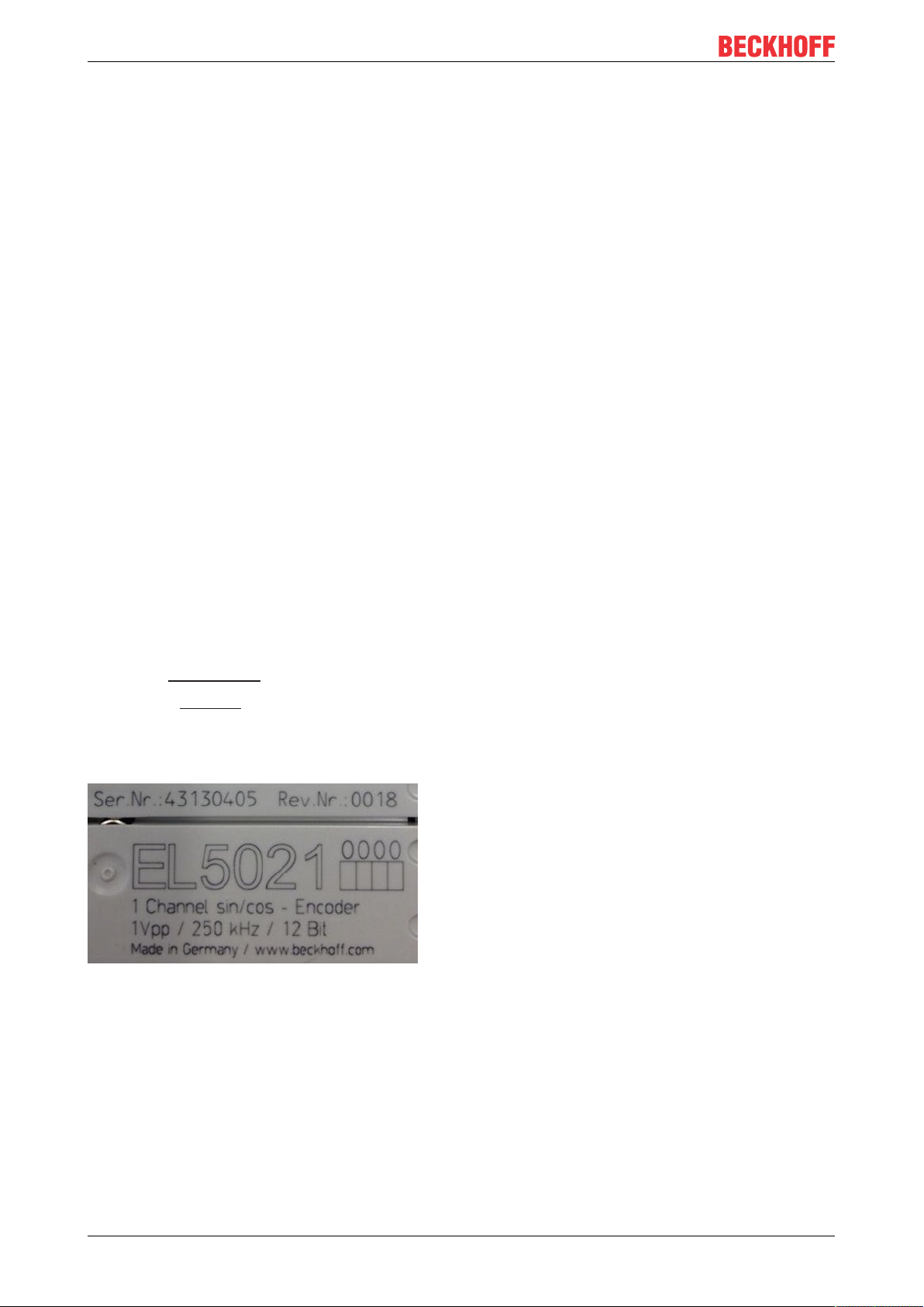
Fig.1: EL5021 EL terminal, standard IP20 IO device with serial/ batch number and revision ID (since
2014/01)
EL50428 Version: 1.5
Page 9
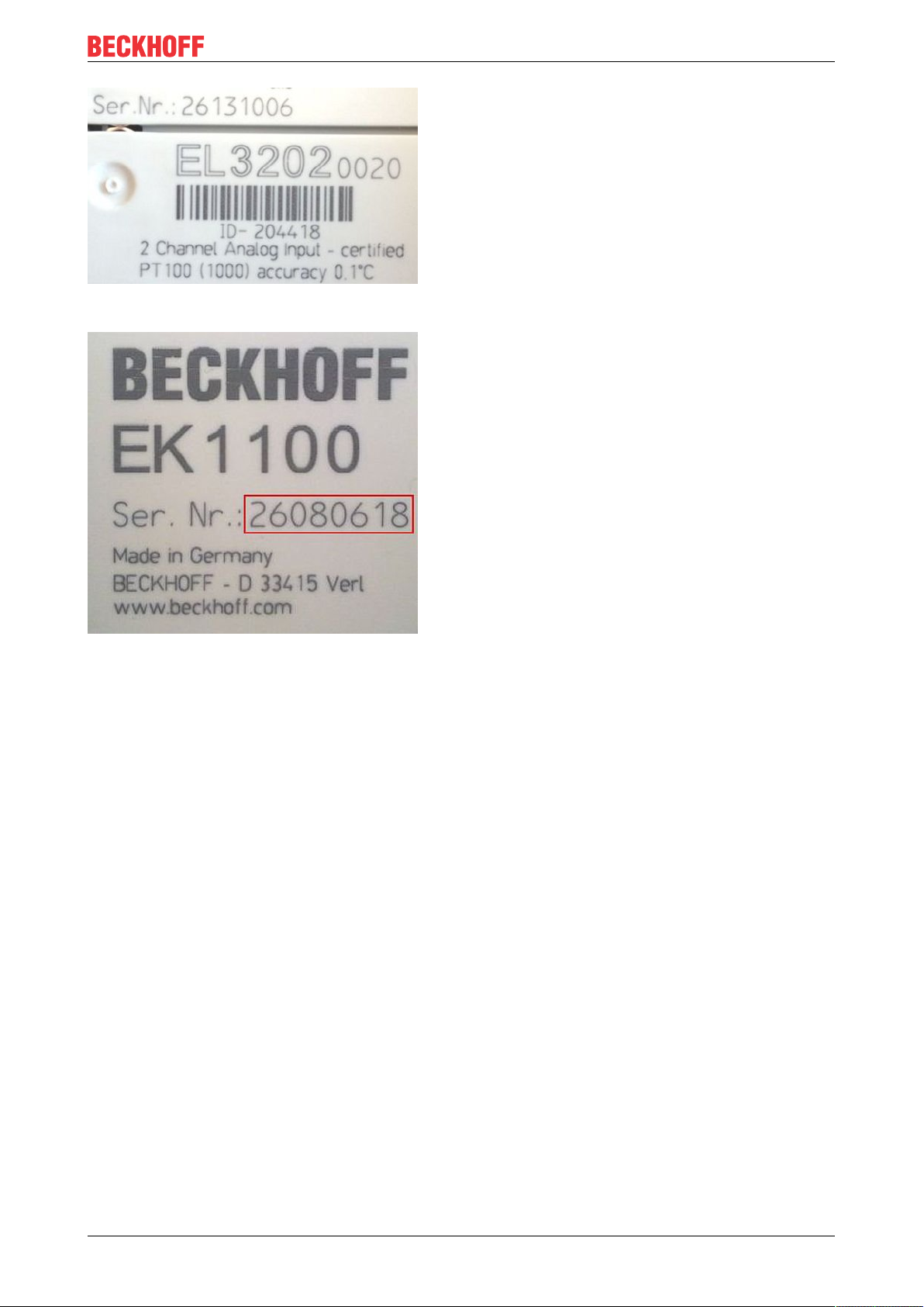
Fig.2: EL3202-0020 with serial/ batch number 26131006 and unique ID-number 204418
Foreword
Fig.3: EK1100 EtherCAT coupler, standard IP20 IO device with serial/ batch number
EL5042 9Version: 1.5
Page 10
Foreword
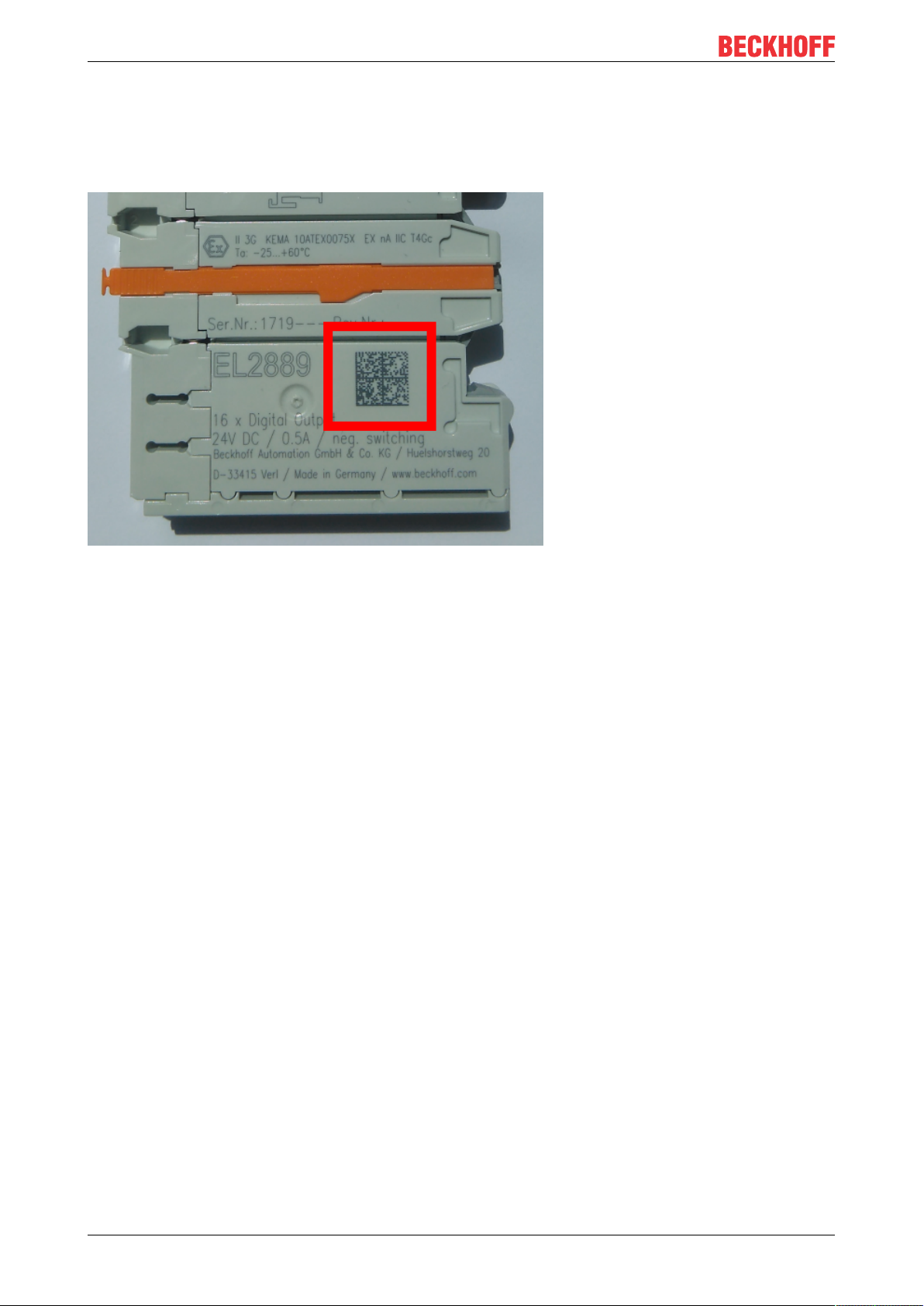
1.4.1 Beckhoff Identification Code (BIC)
The Beckhoff Identification Code (BIC) is increasingly being applied to Beckhoff products to uniquely identify
the product. The BIC is represented as a Data Matrix Code (DMC, code scheme ECC200), the content is
based on the ANSI standard MH10.8.2-2016.
Fig.4: BIC as data matrix code (DMC, code scheme ECC200)
The BIC will be introduced step by step across all product groups.
Depending on the product, it can be found in the following places:
• on the packaging unit
• directly on the product (if space suffices)
• on the packaging unit and the product
The BIC is machine-readable and contains information that can also be used by the customer for handling
and product management.
Each piece of information can be uniquely identified using the so-called data identifier
(ANSIMH10.8.2-2016). The data identifier is followed by a character string. Both together have a maximum
length according to the table below. If the information is shorter, spaces are added to it. The data under
positions 1 to 4 are always available.
The following information is contained:
EL504210 Version: 1.5
Page 11

Item
Type of
no.
information
1 Beckhoff order
number
2 Beckhoff Traceability
Number (BTN)
3 Article description Beckhoff article
4 Quantity Quantity in packaging
5 Batch number Optional: Year and week
6 ID/serial number Optional: Present-day
7 Variant number Optional: Product variant
...
Explanation Data
Beckhoff order number 1P 8 1P072222
Unique serial number,
see note below
description, e.g.
EL1008
unit, e.g. 1, 10, etc.
of production
serial number system,
e.g. with safety products
number on the basis of
standard products
Foreword
Number of digits
identifier
S 12 SBTNk4p562d7
1K 32 1KEL1809
Q 6 Q1
2P 14 2P401503180016
51S 12 51S678294104
30P 32 30PF971, 2*K183
incl. data identifier
Example
Further types of information and data identifiers are used by Beckhoff and serve internal processes.
Structure of the BIC
Example of composite information from item 1 to 4 and 6. The data identifiers are marked in red for better
display:
BTN
An important component of the BIC is the Beckhoff Traceability Number (BTN, item no.2). The BTN is a
unique serial number consisting of eight characters that will replace all other serial number systems at
Beckhoff in the long term (e.g. batch designations on IO components, previous serial number range for
safety products, etc.). The BTN will also be introduced step by step, so it may happen that the BTN is not yet
coded in the BIC.
NOTE
This information has been carefully prepared. However, the procedure described is constantly being further
developed. We reserve the right to revise and change procedures and documentation at any time and without prior notice. No claims for changes can be made from the information, illustrations and descriptions in
this information.
EL5042 11Version: 1.5
Page 12
Product overview
2 Product overview
2.1 Introduction
Fig.5: EL5042
2 channel BiSS-C interface
The EL5042 2-channel BiSS-C interface can be used for direct connection of BiSS-C encoders. As a master,
the EL5042 sends the clock signal to the BiSS-C slave (encoder), which transmits the position data. Here a
position value can be represented in the process image with up to 64 bits, depending on the resolution of the
connected sensor. Furthermore, the EL5042 enables the reading of warning and error status bits, which are
represented separately in the process image. Different operation modes, transmission frequencies and
frame widths can be configured. The EL5042 supports unidirectional BiSS-C communication.
The EL5042 has distributed clocks, so that the position value can be read with precise system synchronicity.
If the distributed clock function is deactivated, the EL5042 cycles are synchronised with the EtherCAT cycle.
Quick links
• Basic function principles [}13]
• Quick start [}41]
• Object description and parameterization [}89]
EL504212 Version: 1.5
Page 13

Product overview
2.2 Technical data
Technical data EL5042
Encoder type BiSS-C, unidirectional
Number of channels 2
Encoder connection D+, D-, C+, CEncoder operating voltage / Encoder supply optionally 5 V DC or 9 V DC
(generated from the 24 V DC power contacts)
Encoder output current max. 0.5 A for both channels
Supply voltage electronics 24 V DC (via power contacts)
Resolution max. 64 bit position, 2 bit status, 8 bit CRC
Data transfer rates up to 10 MHz, variable
Current consumption power contacts typ. 150 mA
Current consumption E-bus typ. 120 mA
Distributed clocks yes
Special features adjustable clock frequency, data length, two status bits
(error and warning) can be evaluated separately
Configuration via EtherCAT master/CoE
Weight approx. 50g
Permissible ambient temperature range during
operation
Permissible ambient temperature range during
storage
Permissible relative humidity 95%, no condensation
Dimensions (W x H x D) approx. 15mm x 100mm x 70mm (width aligned:
Mounting on 35mm mounting rail conforms to EN 60715
Vibration/shock resistance conforms to EN 60068-2-6 / EN 60068-2-27,
EMC immunity/emission conforms to EN 61000-6-2 / EN 61000-6-4
Protection class IP20
Installation position variable
Approvals CE
0°C ... +55°C
-25°C ... +85°C
12mm)
see also installation instructions for enhanced
mechanical load capacity [}31]
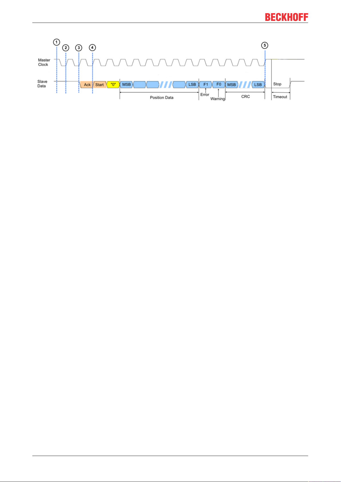
2.3 Basics of BiSS-C technology
The EL5042 support the unidirectional BiSS-C communication. The transmission of the data is triggered by
the master clock. The end of data transmission is identified with the timeout. A typical communication
process is following:
1. Idle state: master clock is high and the BiSS-C slave indicates his ready state also with high value.
2. With the first rising edge of the master clock the synchronous position acquisition is started.
3. After the second rising edge of master clock, the slave responds with a low value “Ack” period.
4. After the “Ack” period is completed, the slave generates a “start” bit, which is always followed by a “0”
bit. The position data is transferred with the 2nd bit after the start bit, according to the data format of
the slave. The communication is synchronized with the master clock. The status bits “Error” and
“Warning” and the CRC are transmitted after the position data.
5. The communication ends with the BiSS timeout. No further pulses are send to the slave, master clock
set the line to the idle state “1”. After the timeout is expired and the slave is ready to transmit new position data, the slave line goes also to the idle state “1”. The communication starts again.
EL5042 13Version: 1.5
Page 14
Product overview
Fig.6: BiSS-C communication process
EL504214 Version: 1.5
Page 15

2.4 Start
For commissioning:
• mount the EL5042 as explained in the chapter Mounting and wiring [}27]
• configure the EL5042 in TwinCAT as described in the chapter Commissioning [}41].
For fast commissioning please refer to chapter Commissioning -> Quick start [}41].
Product overview
EL5042 15Version: 1.5
Page 16

Basics communication
3 Basics communication
3.1 EtherCAT basics
Please refer to the EtherCAT System Documentation for the EtherCAT fieldbus basics.
3.2 EtherCAT cabling – wire-bound
The cable length between two EtherCAT devices must not exceed 100 m. This results from the FastEthernet
technology, which, above all for reasons of signal attenuation over the length of the cable, allows a maximum
link length of 5 + 90 + 5 m if cables with appropriate properties are used. See also the Design
recommendations for the infrastructure for EtherCAT/Ethernet.
Cables and connectors
For connecting EtherCAT devices only Ethernet connections (cables + plugs) that meet the requirements of
at least category 5 (CAt5) according to EN 50173 or ISO/IEC 11801 should be used. EtherCAT uses 4 wires
for signal transfer.
EtherCAT uses RJ45 plug connectors, for example. The pin assignment is compatible with the Ethernet
standard (ISO/IEC 8802-3).
Pin Color of conductor Signal Description
1 yellow TD + Transmission Data +
2 orange TD - Transmission Data 3 white RD + Receiver Data +
6 blue RD - Receiver Data -
Due to automatic cable detection (auto-crossing) symmetric (1:1) or cross-over cables can be used between
EtherCAT devices from Beckhoff.
Recommended cables
Suitable cables for the connection of EtherCAT devices can be found on the Beckhoff website!
E-Bus supply
A bus coupler can supply the EL terminals added to it with the E-bus system voltage of 5V; a coupler is
thereby loadable up to 2A as a rule (see details in respective device documentation).
Information on how much current each EL terminal requires from the E-bus supply is available online and in
the catalogue. If the added terminals require more current than the coupler can supply, then power feed
terminals (e.g. EL9410) must be inserted at appropriate places in the terminal strand.
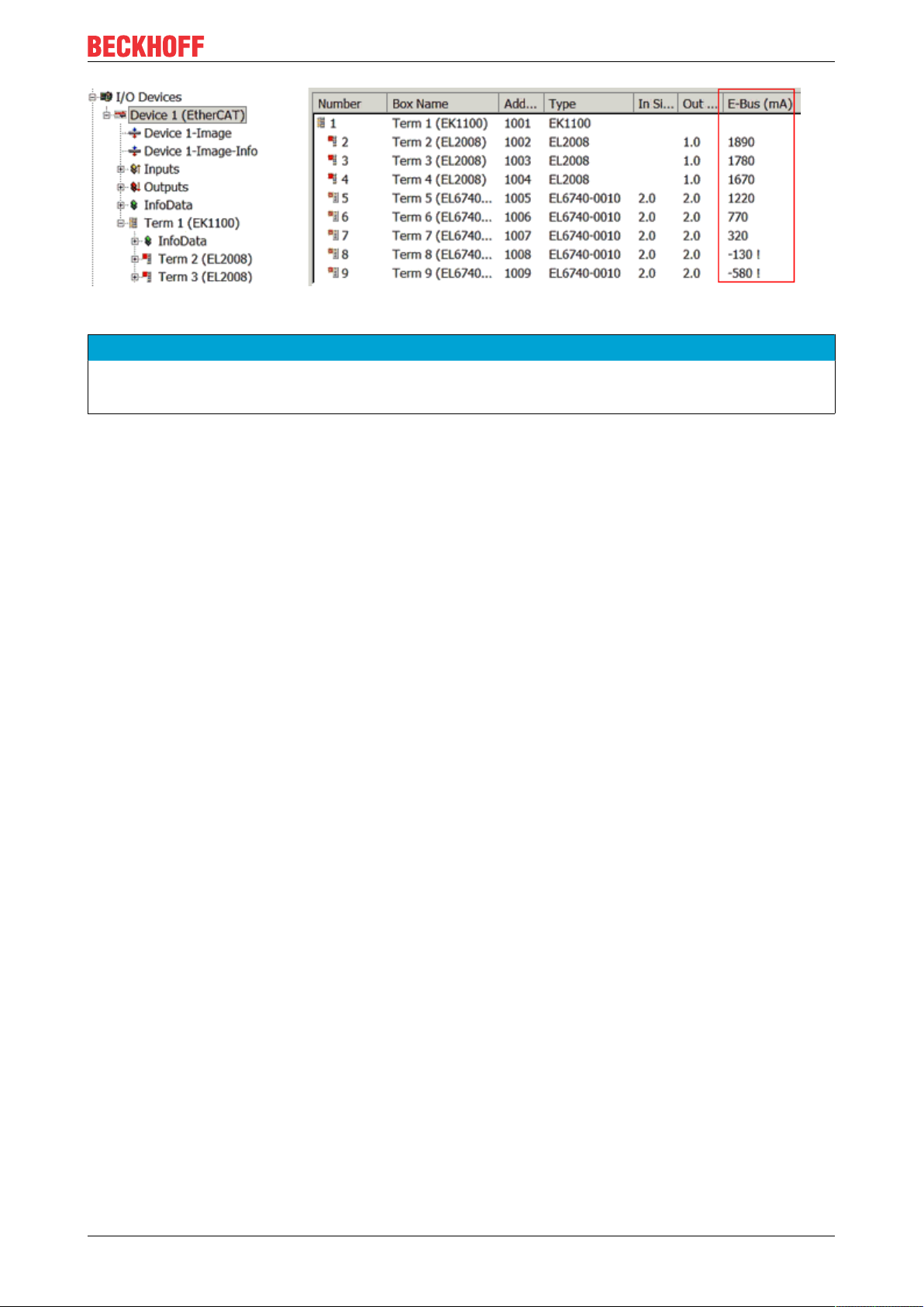
The pre-calculated theoretical maximum E-Bus current is displayed in the TwinCAT System Manager. A
shortfall is marked by a negative total amount and an exclamation mark; a power feed terminal is to be
placed before such a position.
EL504216 Version: 1.5
Page 17
Basics communication
Fig.7: System manager current calculation
NOTE
Malfunction possible!
The same ground potential must be used for the E-Bus supply of all EtherCAT terminals in a terminal block!
3.3 General notes for setting the watchdog
ELxxxx terminals are equipped with a safety feature (watchdog) that switches off the outputs after a
specifiable time e.g. in the event of an interruption of the process data traffic, depending on the device and
settings, e.g. in OFF state.
The EtherCAT slave controller (ESC) in the EL2xxx terminals features 2 watchdogs:
• SM watchdog (default: 100 ms)
• PDI watchdog (default: 100 ms)
SM watchdog (SyncManager Watchdog)
The SyncManager watchdog is reset after each successful EtherCAT process data communication with the
terminal. If no EtherCAT process data communication takes place with the terminal for longer than the set
and activated SM watchdog time, e.g. in the event of a line interruption, the watchdog is triggered and the
outputs are set to FALSE. The OP state of the terminal is unaffected. The watchdog is only reset after a
successful EtherCAT process data access. Set the monitoring time as described below.
The SyncManager watchdog monitors correct and timely process data communication with the ESC from the
EtherCAT side.
PDI watchdog (Process Data Watchdog)
If no PDI communication with the EtherCAT slave controller (ESC) takes place for longer than the set and
activated PDI watchdog time, this watchdog is triggered.
PDI (Process Data Interface) is the internal interface between the ESC and local processors in the EtherCAT
slave, for example. The PDI watchdog can be used to monitor this communication for failure.
The PDI watchdog monitors correct and timely process data communication with the ESC from the
application side.
The settings of the SM- and PDI-watchdog must be done for each slave separately in the TwinCAT System
Manager.
EL5042 17Version: 1.5
Page 18
Basics communication
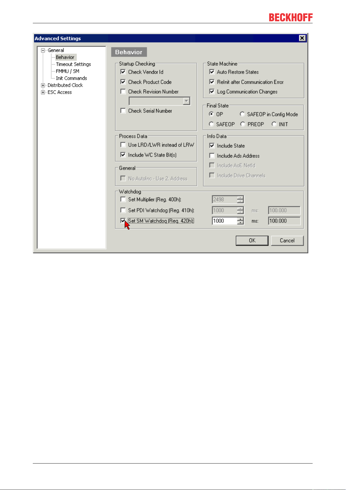
Fig.8: EtherCAT tab -> Advanced Settings -> Behavior -> Watchdog
Notes:
• the multiplier is valid for both watchdogs.
• each watchdog has its own timer setting, the outcome of this in summary with the multiplier is a
resulting time.
• Important: the multiplier/timer setting is only loaded into the slave at the start up, if the checkbox is
activated.
If the checkbox is not activated, nothing is downloaded and the ESC settings remain unchanged.
Multiplier
Multiplier
Both watchdogs receive their pulses from the local terminal cycle, divided by the watchdog multiplier:
1/25 MHz * (watchdog multiplier + 2) = 100µs (for default setting of 2498 for the multiplier)
The standard setting of 1000 for the SM watchdog corresponds to a release time of 100ms.
The value in multiplier + 2 corresponds to the number of basic 40 ns ticks representing a watchdog tick.
The multiplier can be modified in order to adjust the watchdog time over a larger range.
EL504218 Version: 1.5
Page 19

Basics communication
Example "Set SM watchdog"
This checkbox enables manual setting of the watchdog times. If the outputs are set and the EtherCAT
communication is interrupted, the SM watchdog is triggered after the set time and the outputs are erased.
This setting can be used for adapting a terminal to a slower EtherCAT master or long cycle times. The
default SM watchdog setting is 100ms. The setting range is 0...65535. Together with a multiplier with a
range of 1...65535 this covers a watchdog period between 0...~170 seconds.
Calculation
Multiplier = 2498 → watchdog base time = 1 / 25MHz * (2498 + 2) = 0.0001seconds = 100µs
SM watchdog = 10000 → 10000 * 100µs = 1second watchdog monitoring time
CAUTION
Undefined state possible!
The function for switching off of the SM watchdog via SM watchdog = 0 is only implemented in terminals
from version -0016. In previous versions this operating mode should not be used.
CAUTION
Damage of devices and undefined state possible!
If the SM watchdog is activated and a value of 0 is entered the watchdog switches off completely. This is
the deactivation of the watchdog! Set outputs are NOT set in a safe state, if the communication is interrupted.
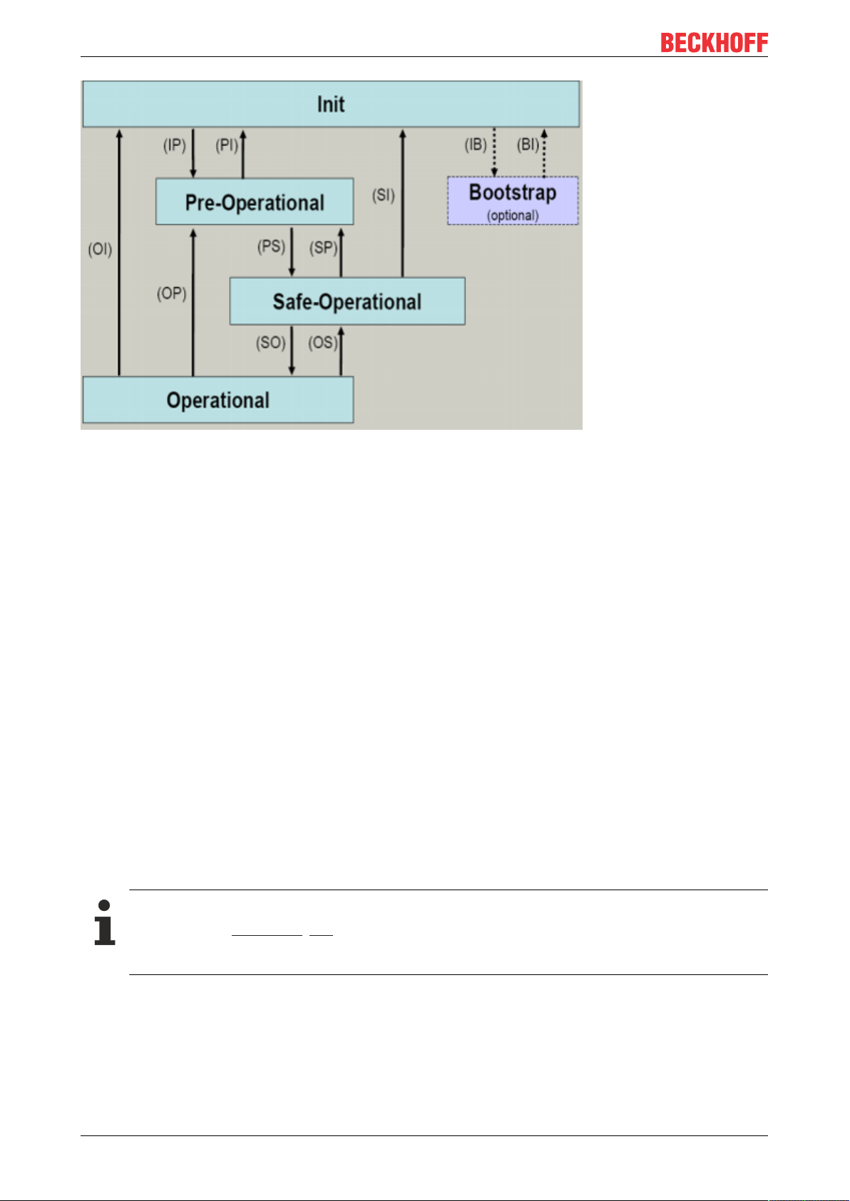
3.4 EtherCAT State Machine
The state of the EtherCAT slave is controlled via the EtherCAT State Machine (ESM). Depending upon the
state, different functions are accessible or executable in the EtherCAT slave. Specific commands must be
sent by the EtherCAT master to the device in each state, particularly during the bootup of the slave.
A distinction is made between the following states:
• Init
• Pre-Operational
• Safe-Operational and
• Operational
• Boot
The regular state of each EtherCAT slave after bootup is the OP state.
EL5042 19Version: 1.5
Page 20
Basics communication
Fig.9: States of the EtherCAT State Machine
Init
After switch-on the EtherCAT slave in the Init state. No mailbox or process data communication is possible.
The EtherCAT master initializes sync manager channels 0 and 1 for mailbox communication.
Pre-Operational (Pre-Op)
During the transition between Init and Pre-Op the EtherCAT slave checks whether the mailbox was initialized
correctly.
In Pre-Op state mailbox communication is possible, but not process data communication. The EtherCAT
master initializes the sync manager channels for process data (from sync manager channel 2), the FMMU
channels and, if the slave supports configurable mapping, PDO mapping or the sync manager PDO
assignment. In this state the settings for the process data transfer and perhaps terminal-specific parameters
that may differ from the default settings are also transferred.
Safe-Operational (Safe-Op)
During transition between Pre-Op and Safe-Op the EtherCAT slave checks whether the sync manager
channels for process data communication and, if required, the distributed clocks settings are correct. Before
it acknowledges the change of state, the EtherCAT slave copies current input data into the associated DPRAM areas of the EtherCAT slave controller (ECSC).
In Safe-Op state mailbox and process data communication is possible, although the slave keeps its outputs
in a safe state, while the input data are updated cyclically.
Outputs in SAFEOP state
The default set watchdog [}17] monitoring sets the outputs of the module in a safe state - depending on the settings in SAFEOP and OP - e.g. in OFF state. If this is prevented by deactivation of the
watchdog monitoring in the module, the outputs can be switched or set also in the SAFEOP state.
Operational (Op)
Before the EtherCAT master switches the EtherCAT slave from Safe-Op to Op it must transfer valid output
data.
In the Op state the slave copies the output data of the masters to its outputs. Process data and mailbox
communication is possible.
EL504220 Version: 1.5
Page 21

Basics communication
Boot
In the Boot state the slave firmware can be updated. The Boot state can only be reached via the Init state.
In the Boot state mailbox communication via the file access over EtherCAT (FoE) protocol is possible, but no
other mailbox communication and no process data communication.
3.5 CoE Interface
General description
The CoE interface (CAN application protocol over EtherCAT)) is used for parameter management of
EtherCAT devices. EtherCAT slaves or the EtherCAT master manage fixed (read only) or variable
parameters which they require for operation, diagnostics or commissioning.
CoE parameters are arranged in a table hierarchy. In principle, the user has read access via the fieldbus.
The EtherCAT master (TwinCAT System Manager) can access the local CoE lists of the slaves via
EtherCAT in read or write mode, depending on the attributes.
Different CoE parameter types are possible, including string (text), integer numbers, Boolean values or larger
byte fields. They can be used to describe a wide range of features. Examples of such parameters include
manufacturer ID, serial number, process data settings, device name, calibration values for analog
measurement or passwords.
The order is specified in 2 levels via hexadecimal numbering: (main)index, followed by subindex. The value
ranges are
• Index: 0x0000 …0xFFFF (0...65535
• SubIndex: 0x00…0xFF (0...255
dez
)
dez
)
A parameter localized in this way is normally written as 0x8010:07, with preceding "x" to identify the
hexadecimal numerical range and a colon between index and subindex.
The relevant ranges for EtherCAT fieldbus users are:
• 0x1000: This is where fixed identity information for the device is stored, including name, manufacturer,
serial number etc., plus information about the current and available process data configurations.
• 0x8000: This is where the operational and functional parameters for all channels are stored, such as
filter settings or output frequency.
Other important ranges are:
• 0x4000: here are the channel parameters for some EtherCAT devices. Historically, this was the first
parameter area before the 0x8000 area was introduced. EtherCAT devices that were previously
equipped with parameters in 0x4000 and changed to 0x8000 support both ranges for compatibility
reasons and mirror internally.
• 0x6000: Input PDOs ("input" from the perspective of the EtherCAT master)
• 0x7000: Output PDOs ("output" from the perspective of the EtherCAT master)
Availability
Not every EtherCAT device must have a CoE list. Simple I/O modules without dedicated processor
usually have no variable parameters and therefore no CoE list.
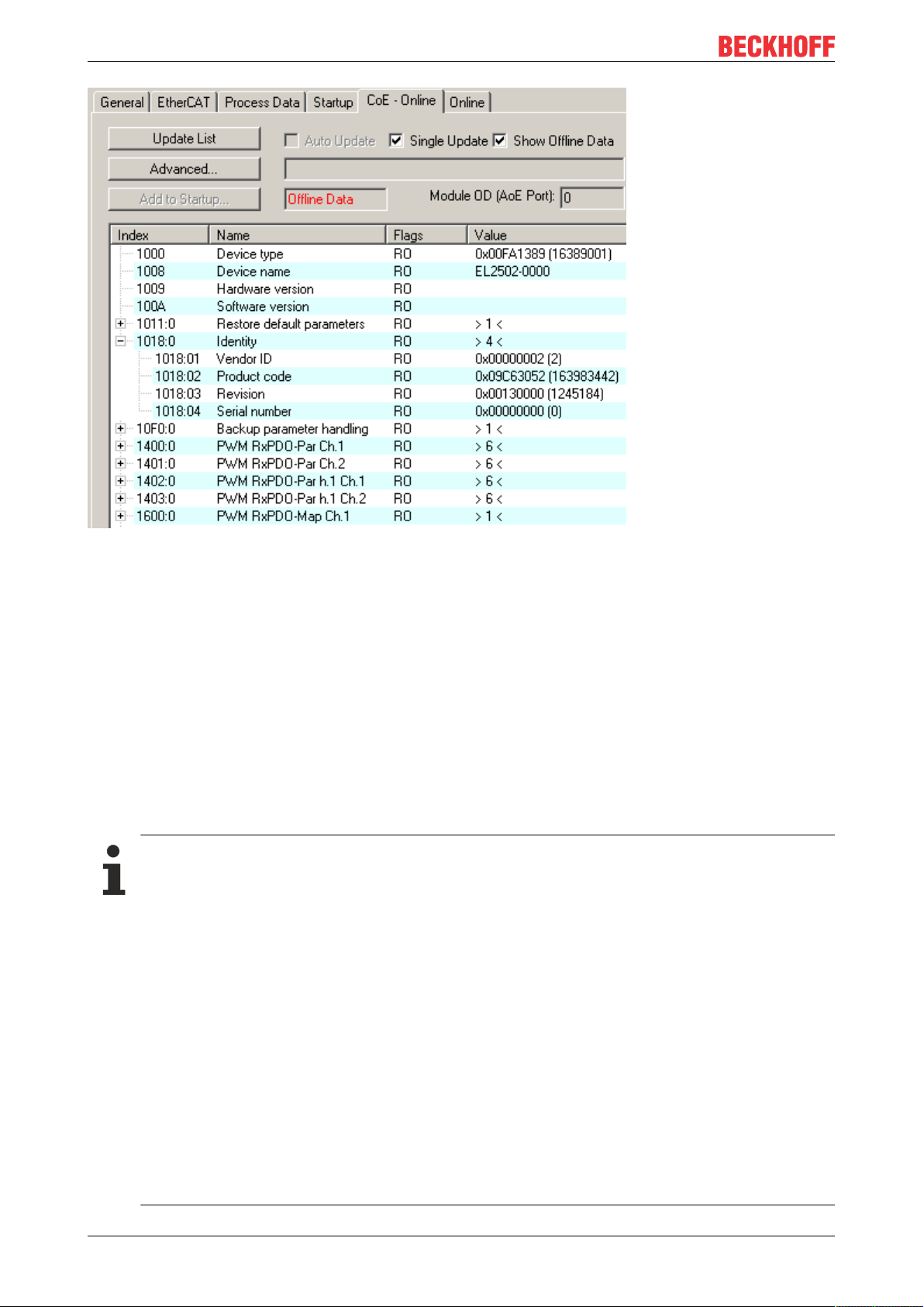
If a device has a CoE list, it is shown in the TwinCAT System Manager as a separate tab with a listing of the
elements:
EL5042 21Version: 1.5
Page 22
Basics communication
Fig.10: "CoE Online " tab
The figure above shows the CoE objects available in device "EL2502", ranging from 0x1000 to 0x1600. The
subindices for 0x1018 are expanded.
Data management and function "NoCoeStorage"
Some parameters, particularly the setting parameters of the slave, are configurable and writeable. This can
be done in write or read mode
• via the System Manager (Fig. "CoE Online" tab) by clicking
This is useful for commissioning of the system/slaves. Click on the row of the index to be
parameterised and enter a value in the "SetValue" dialog.
• from the control system/PLC via ADS, e.g. through blocks from the TcEtherCAT.lib library
This is recommended for modifications while the system is running or if no System Manager or
operating staff are available.
Data management
If slave CoE parameters are modified online, Beckhoff devices store any changes in a fail-safe
manner in the EEPROM, i.e. the modified CoE parameters are still available after a restart.
The situation may be different with other manufacturers.
An EEPROM is subject to a limited lifetime with respect to write operations. From typically 100,000
write operations onwards it can no longer be guaranteed that new (changed) data are reliably saved
or are still readable. This is irrelevant for normal commissioning. However, if CoE parameters are
continuously changed via ADS at machine runtime, it is quite possible for the lifetime limit to be
reached. Support for the NoCoeStorage function, which suppresses the saving of changed CoE values, depends on the firmware version.
Please refer to the technical data in this documentation as to whether this applies to the respective
device.
• If the function is supported: the function is activated by entering the code word 0x12345678 once
in CoE 0xF008 and remains active as long as the code word is not changed. After switching the
device on it is then inactive. Changed CoE values are not saved in the EEPROM and can thus
be changed any number of times.
• Function is not supported: continuous changing of CoE values is not permissible in view of the
lifetime limit.
EL504222 Version: 1.5
Page 23
Startup list
Changes in the local CoE list of the terminal are lost if the terminal is replaced. If a terminal is replaced with a new Beckhoff terminal, it will have the default settings. It is therefore advisable to link
all changes in the CoE list of an EtherCAT slave with the Startup list of the slave, which is processed whenever the EtherCAT fieldbus is started. In this way a replacement EtherCAT slave can
automatically be parameterized with the specifications of the user.
If EtherCAT slaves are used which are unable to store local CoE values permanently, the Startup
list must be used.
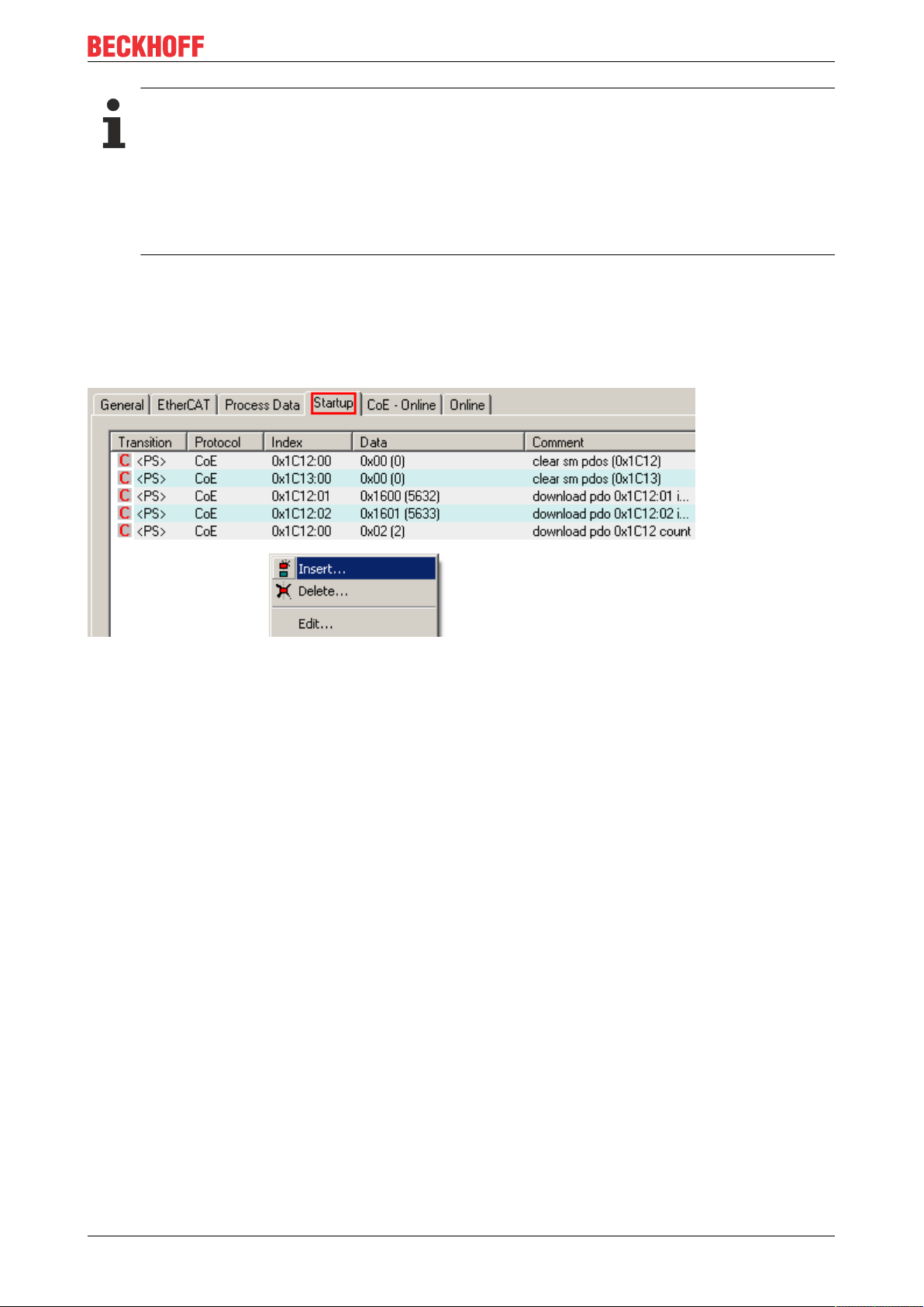
Recommended approach for manual modification of CoE parameters
• Make the required change in the System Manager
The values are stored locally in the EtherCAT slave
• If the value is to be stored permanently, enter it in the Startup list.
The order of the Startup entries is usually irrelevant.
Basics communication
Fig.11: Startup list in the TwinCAT System Manager
The Startup list may already contain values that were configured by the System Manager based on the ESI
specifications. Additional application-specific entries can be created.
Online/offline list
While working with the TwinCAT System Manager, a distinction has to be made whether the EtherCAT
device is "available", i.e. switched on and linked via EtherCAT and therefore online, or whether a
configuration is created offline without connected slaves.
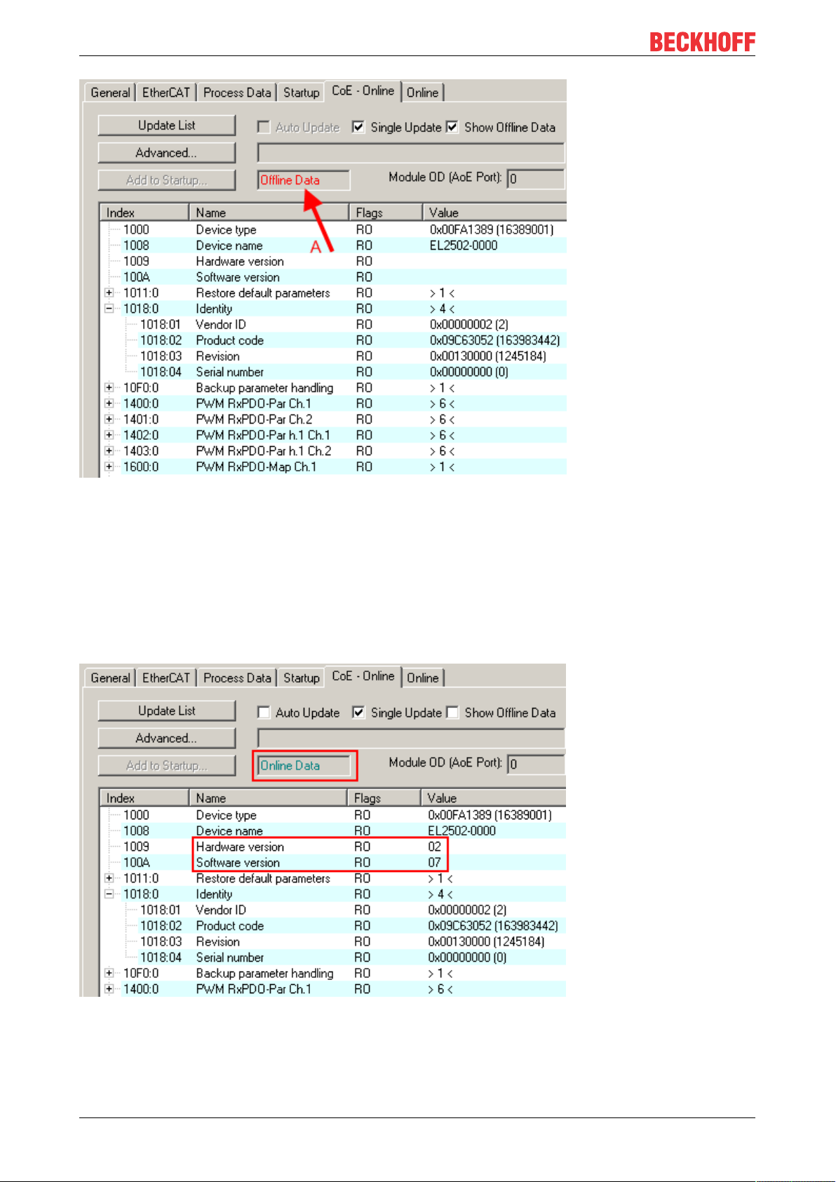
In both cases a CoE list as shown in Fig. “CoE online tab” is displayed. The connectivity is shown as offline/
online.
• If the slave is offline
◦ The offline list from the ESI file is displayed. In this case modifications are not meaningful or
possible.
◦ The configured status is shown under Identity.
◦ No firmware or hardware version is displayed, since these are features of the physical device.
◦ Offline is shown in red.
EL5042 23Version: 1.5
Page 24
Basics communication
Fig.12: Offline list
• If the slave is online
◦ The actual current slave list is read. This may take several seconds, depending on the size and
cycle time.
◦ The actual identity is displayed
◦ The firmware and hardware version of the equipment according to the electronic information is
displayed
◦ Online is shown in green.
Fig.13: Online list
EL504224 Version: 1.5
Page 25

Basics communication
Channel-based order
The CoE list is available in EtherCAT devices that usually feature several functionally equivalent channels.
For example, a 4-channel analog 0...10V input terminal also has 4 logical channels and therefore 4 identical
sets of parameter data for the channels. In order to avoid having to list each channel in the documentation,
the placeholder "n" tends to be used for the individual channel numbers.
In the CoE system 16 indices, each with 255 subindices, are generally sufficient for representing all channel
parameters. The channel-based order is therefore arranged in 16
dec
/10
steps. The parameter range
hex
0x8000 exemplifies this:
• Channel 0: parameter range 0x8000:00 ... 0x800F:255
• Channel 1: parameter range 0x8010:00 ... 0x801F:255
• Channel 2: parameter range 0x8020:00 ... 0x802F:255
• ...
This is generally written as 0x80n0.
Detailed information on the CoE interface can be found in the EtherCAT system documentation on the
Beckhoff website.
EL5042 25Version: 1.5
Page 26

Basics communication
3.6 Distributed Clock
The distributed clock represents a local clock in the EtherCAT slave controller (ESC) with the following
characteristics:
• Unit 1 ns
• Zero point 1.1.2000 00:00
• Size 64 bit (sufficient for the next 584 years; however, some EtherCAT slaves only offer 32-bit support,
i.e. the variable overflows after approx. 4.2 seconds)
• The EtherCAT master automatically synchronizes the local clock with the master clock in the EtherCAT
bus with a precision of < 100 ns.
For detailed information please refer to the EtherCAT system description.
EL504226 Version: 1.5
Page 27
Mounting and wiring
4 Mounting and wiring
4.1 Instructions for ESD protection
NOTE
Destruction of the devices by electrostatic discharge possible!
The devices contain components at risk from electrostatic discharge caused by improper handling.
• Please ensure you are electrostatically discharged and avoid touching the contacts of the device directly.
• Avoid contact with highly insulating materials (synthetic fibers, plastic film etc.).
• Surroundings (working place, packaging and personnel) should by grounded probably, when handling
with the devices.
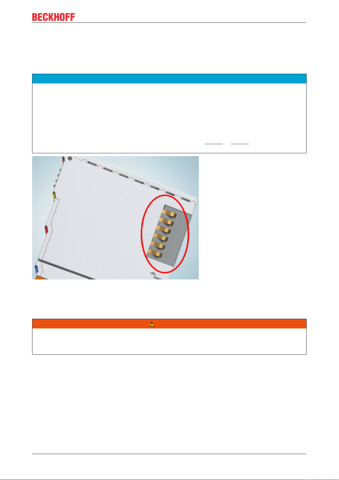
• Each assembly must be terminated at the right hand end with an EL9011 or EL9012 bus end cap, to ensure the protection class and ESD protection.
Fig.14: Spring contacts of the Beckhoff I/O components
4.2 Installation on mounting rails
WARNING
Risk of electric shock and damage of device!
Bring the bus terminal system into a safe, powered down state before starting installation, disassembly or
wiring of the bus terminals!
EL5042 27Version: 1.5
Page 28
Mounting and wiring
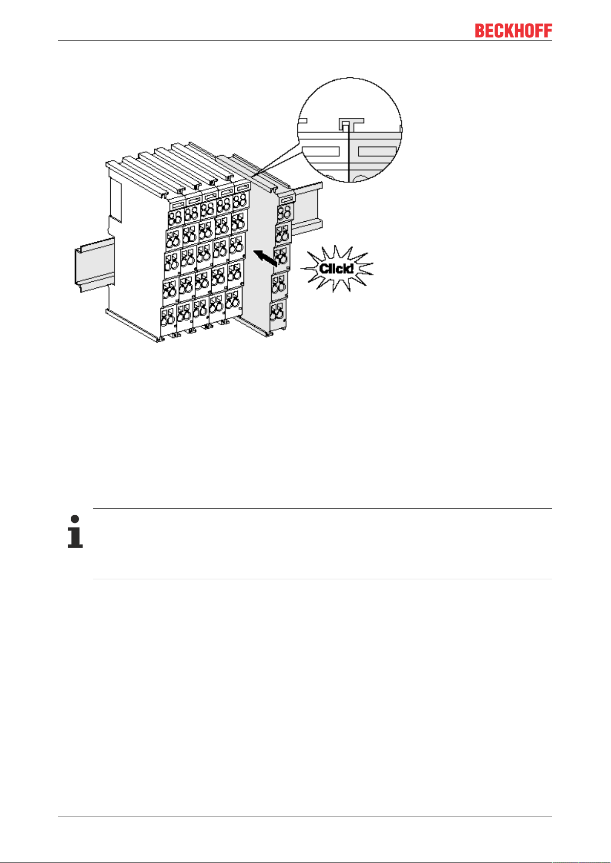
Assembly
Fig.15: Attaching on mounting rail
The bus coupler and bus terminals are attached to commercially available 35mm mounting rails (DIN rails
according to EN60715) by applying slight pressure:
1. First attach the fieldbus coupler to the mounting rail.
2. The bus terminals are now attached on the right-hand side of the fieldbus coupler. Join the components with tongue and groove and push the terminals against the mounting rail, until the lock clicks
onto the mounting rail.
If the terminals are clipped onto the mounting rail first and then pushed together without tongue and
groove, the connection will not be operational! When correctly assembled, no significant gap should
be visible between the housings.
Fixing of mounting rails
The locking mechanism of the terminals and couplers extends to the profile of the mounting rail. At
the installation, the locking mechanism of the components must not come into conflict with the fixing
bolts of the mounting rail. To mount the mounting rails with a height of 7.5mm under the terminals
and couplers, you should use flat mounting connections (e.g. countersunk screws or blind rivets).
EL504228 Version: 1.5
Page 29
Mounting and wiring
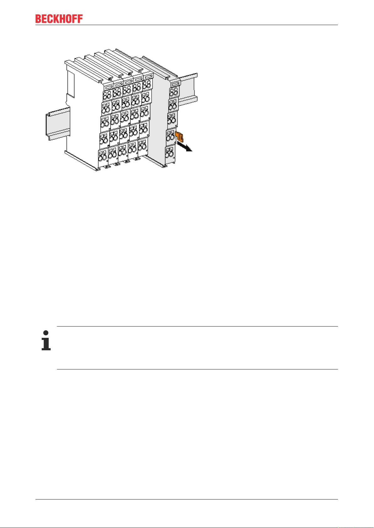
Disassembly
Fig.16: Disassembling of terminal
Each terminal is secured by a lock on the mounting rail, which must be released for disassembly:
1. Pull the terminal by its orange-colored lugs approximately 1cm away from the mounting rail. In doing
so for this terminal the mounting rail lock is released automatically and you can pull the terminal out of
the bus terminal block easily without excessive force.
2. Grasp the released terminal with thumb and index finger simultaneous at the upper and lower grooved
housing surfaces and pull the terminal out of the bus terminal block.
Connections within a bus terminal block
The electric connections between the Bus Coupler and the Bus Terminals are automatically realized by
joining the components:
• The six spring contacts of the K-Bus/E-Bus deal with the transfer of the data and the supply of the Bus
Terminal electronics.
• The power contacts deal with the supply for the field electronics and thus represent a supply rail within
the bus terminal block. The power contacts are supplied via terminals on the Bus Coupler (up to 24V)
or for higher voltages via power feed terminals.
Power Contacts
During the design of a bus terminal block, the pin assignment of the individual Bus Terminals must
be taken account of, since some types (e.g. analog Bus Terminals or digital 4-channel Bus Terminals) do not or not fully loop through the power contacts. Power Feed Terminals (KL91xx, KL92xx
or EL91xx, EL92xx) interrupt the power contacts and thus represent the start of a new supply rail.
PE power contact
The power contact labeled PE can be used as a protective earth. For safety reasons this contact mates first
when plugging together, and can ground short-circuit currents of up to 125A.
EL5042 29Version: 1.5
Page 30
Mounting and wiring
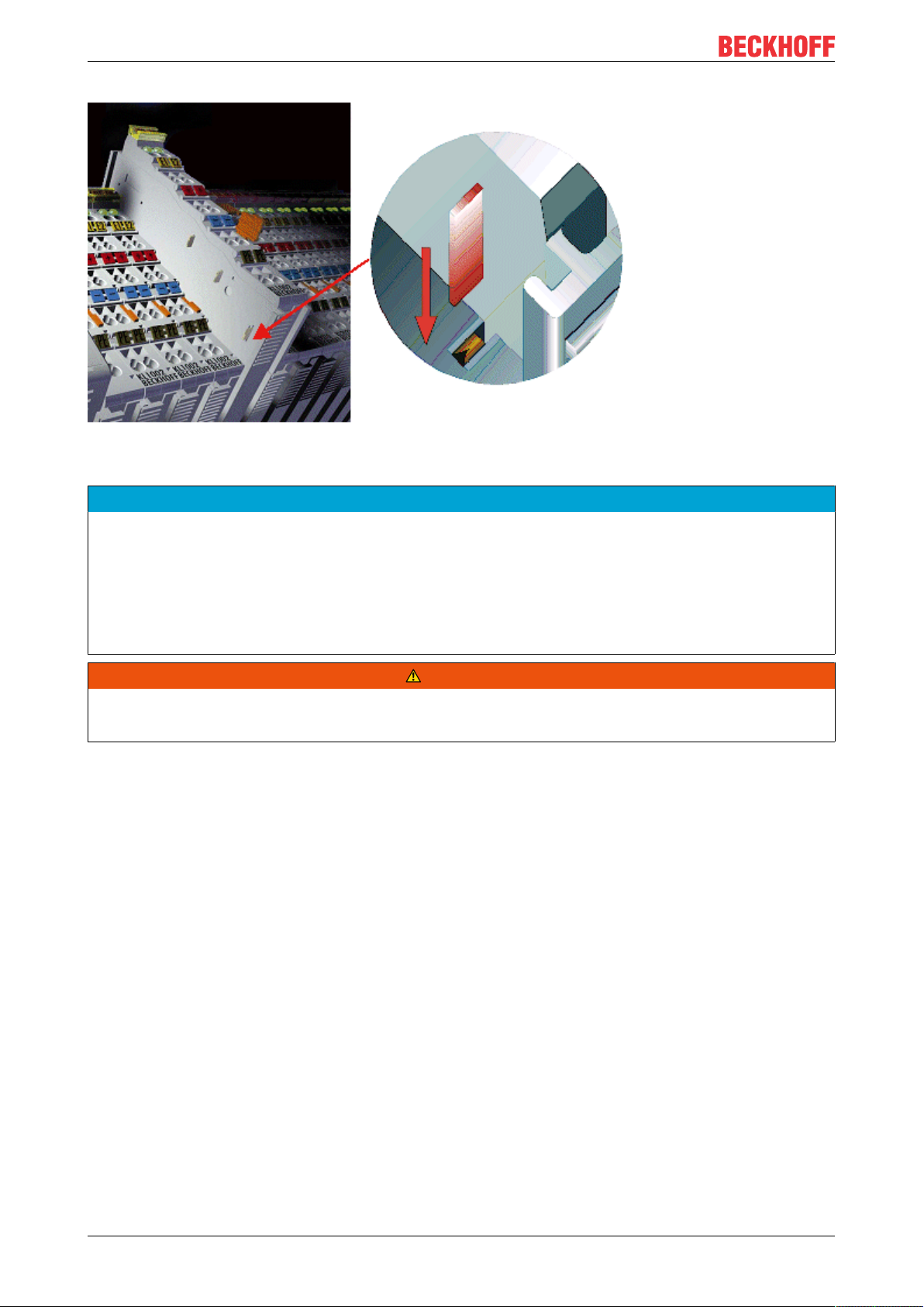
Fig.17: Power contact on left side
NOTE
Possible damage of the device
Note that, for reasons of electromagnetic compatibility, the PE contacts are capacitatively coupled to the
mounting rail. This may lead to incorrect results during insulation testing or to damage on the terminal (e.g.
disruptive discharge to the PE line during insulation testing of a consumer with a nominal voltage of 230V).
For insulation testing, disconnect the PE supply line at the Bus Coupler or the Power Feed Terminal! In order to decouple further feed points for testing, these Power Feed Terminals can be released and pulled at
least 10mm from the group of terminals.
WARNING
Risk of electric shock!
The PE power contact must not be used for other potentials!
EL504230 Version: 1.5
Page 31

Mounting and wiring
4.3 Installation instructions for enhanced mechanical load capacity
WARNING
Risk of injury through electric shock and damage to the device!
Bring the Bus Terminal system into a safe, de-energized state before starting mounting, disassembly or
wiring of the Bus Terminals!
Additional checks
The terminals have undergone the following additional tests:
Verification Explanation
Vibration 10 frequency runs in 3 axes
6 Hz < f < 60 Hz displacement 0.35 mm, constant amplitude
60.1Hz<f<500Hz acceleration 5g, constant amplitude
Shocks 1000 shocks in each direction, in 3 axes
25 g, 6 ms
Additional installation instructions
For terminals with enhanced mechanical load capacity, the following additional installation instructions apply:
• The enhanced mechanical load capacity is valid for all permissible installation positions
• Use a mounting rail according to EN 60715 TH35-15
• Fix the terminal segment on both sides of the mounting rail with a mechanical fixture, e.g. an earth
terminal or reinforced end clamp
• The maximum total extension of the terminal segment (without coupler) is:
64 terminals (12 mm mounting with) or 32 terminals (24 mm mounting with)
• Avoid deformation, twisting, crushing and bending of the mounting rail during edging and installation of
the rail
• The mounting points of the mounting rail must be set at 5 cm intervals
• Use countersunk head screws to fasten the mounting rail
• The free length between the strain relief and the wire connection should be kept as short as possible. A
distance of approx. 10 cm should be maintained to the cable duct.
4.4 Connection
4.4.1 Connection system
WARNING
Risk of electric shock and damage of device!
Bring the bus terminal system into a safe, powered down state before starting installation, disassembly or
wiring of the bus terminals!
Overview
The Bus Terminal system offers different connection options for optimum adaptation to the respective
application:
• The terminals of ELxxxx and KLxxxx series with standard wiring include electronics and connection
level in a single enclosure.
EL5042 31Version: 1.5
Page 32

Mounting and wiring
• The terminals of ESxxxx and KSxxxx series feature a pluggable connection level and enable steady
wiring while replacing.
• The High Density Terminals (HD Terminals) include electronics and connection level in a single
enclosure and have advanced packaging density.
Standard wiring (ELxxxx / KLxxxx)
Fig.18: Standard wiring
The terminals of ELxxxx and KLxxxx series have been tried and tested for years.
They feature integrated screwless spring force technology for fast and simple assembly.
Pluggable wiring (ESxxxx / KSxxxx)
Fig.19: Pluggable wiring
The terminals of ESxxxx and KSxxxx series feature a pluggable connection level.
The assembly and wiring procedure is the same as for the ELxxxx and KLxxxx series.
The pluggable connection level enables the complete wiring to be removed as a plug connector from the top
of the housing for servicing.
The lower section can be removed from the terminal block by pulling the unlocking tab.
Insert the new component and plug in the connector with the wiring. This reduces the installation time and
eliminates the risk of wires being mixed up.
The familiar dimensions of the terminal only had to be changed slightly. The new connector adds about 3
mm. The maximum height of the terminal remains unchanged.
A tab for strain relief of the cable simplifies assembly in many applications and prevents tangling of individual
connection wires when the connector is removed.
Conductor cross sections between 0.08mm2 and 2.5mm2 can continue to be used with the proven spring
force technology.
The overview and nomenclature of the product names for ESxxxx and KSxxxx series has been retained as
known from ELxxxx and KLxxxx series.
EL504232 Version: 1.5
Page 33

Mounting and wiring
High Density Terminals (HD Terminals)
Fig.20: High Density Terminals
The Bus Terminals from these series with 16 terminal points are distinguished by a particularly compact
design, as the packaging density is twice as large as that of the standard 12mm Bus Terminals. Massive
conductors and conductors with a wire end sleeve can be inserted directly into the spring loaded terminal
point without tools.
Wiring HD Terminals
The High Density Terminals of the ELx8xx and KLx8xx series doesn't support pluggable wiring.
Ultrasonically "bonded" (ultrasonically welded) conductors
Ultrasonically “bonded" conductors
It is also possible to connect the Standard and High Density Terminals with ultrasonically
"bonded" (ultrasonically welded) conductors. In this case, please note the tables concerning the
wire-size width below!
EL5042 33Version: 1.5
Page 34

Mounting and wiring
4.4.2 Wiring
WARNING
Risk of electric shock and damage of device!
Bring the bus terminal system into a safe, powered down state before starting installation, disassembly or
wiring of the Bus Terminals!
Terminals for standard wiring ELxxxx/KLxxxx and for pluggable wiring ESxxxx/KSxxxx
Fig.21: Connecting a cable on a terminal point
Up to eight terminal points enable the connection of solid or finely stranded cables to the Bus Terminal. The
terminal points are implemented in spring force technology. Connect the cables as follows:
1. Open a terminal point by pushing a screwdriver straight against the stop into the square opening
above the terminal point. Do not turn the screwdriver or move it alternately (don't toggle).
2. The wire can now be inserted into the round terminal opening without any force.
3. The terminal point closes automatically when the pressure is released, holding the wire securely and
permanently.
See the following table for the suitable wire size width.
Terminal housing ELxxxx, KLxxxx ESxxxx, KSxxxx
Wire size width (single core wires) 0.08 ... 2.5mm
Wire size width (fine-wire conductors) 0.08 ... 2.5mm
Wire size width (conductors with a wire end sleeve) 0.14 ... 1.5mm
2
2
2
0.08 ... 2.5mm
0,08 ... 2.5mm
0.14 ... 1.5mm
2
2
2
Wire stripping length 8 ... 9mm 9 ... 10mm
High Density Terminals (HD Terminals [}33]) with 16 terminal points
The conductors of the HD Terminals are connected without tools for single-wire conductors using the direct
plug-in technique, i.e. after stripping the wire is simply plugged into the terminal point. The cables are
released, as usual, using the contact release with the aid of a screwdriver. See the following table for the
suitable wire size width.
EL504234 Version: 1.5
Page 35

Mounting and wiring
Terminal housing High Density Housing
Wire size width (single core wires) 0.08 ... 1.5mm
Wire size width (fine-wire conductors) 0.25 ... 1.5mm
Wire size width (conductors with a wire end sleeve) 0.14 ... 0.75mm
Wire size width (ultrasonically “bonded" conductors) only 1.5mm
2
2
2
2
Wire stripping length 8 ... 9mm
4.4.3 Shielding
Shielding
Encoder, analog sensors and actors should always be connected with shielded, twisted paired
wires.
4.5 Installation positions
NOTE
Constraints regarding installation position and operating temperature range
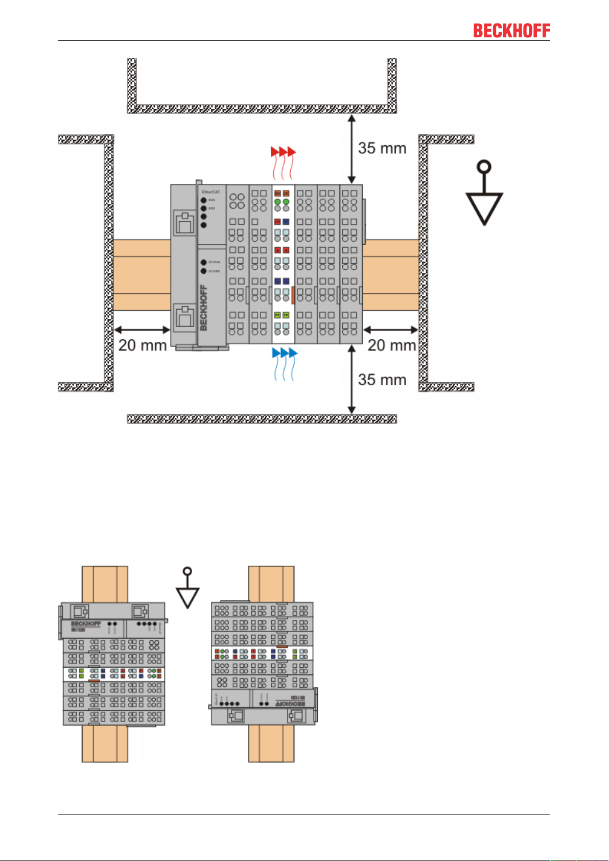
Please refer to the technical data for a terminal to ascertain whether any restrictions regarding the installation position and/or the operating temperature range have been specified. When installing high power dissipation terminals ensure that an adequate spacing is maintained between other components above and below the terminal in order to guarantee adequate ventilation!
Optimum installation position (standard)
The optimum installation position requires the mounting rail to be installed horizontally and the connection
surfaces of the EL/KL terminals to face forward (see Fig. “Recommended distances for standard installation
position”). The terminals are ventilated from below, which enables optimum cooling of the electronics through
convection. "From below" is relative to the acceleration of gravity.
EL5042 35Version: 1.5
Page 36
Mounting and wiring
Fig.22: Recommended distances for standard installation position
Compliance with the distances shown in Fig. “Recommended distances for standard installation position” is
recommended.
Other installation positions
All other installation positions are characterized by different spatial arrangement of the mounting rail - see
Fig “Other installation positions”.
The minimum distances to ambient specified above also apply to these installation positions.
EL504236 Version: 1.5
Page 37

Fig.23: Other installation positions
Mounting and wiring
EL5042 37Version: 1.5
Page 38

Mounting and wiring
4.6 Positioning of passive Terminals
Hint for positioning of passive terminals in the bus terminal block
EtherCAT Terminals (ELxxxx / ESxxxx), which do not take an active part in data transfer within the
bus terminal block are so called passive terminals. The passive terminals have no current consumption out of the E-Bus.
To ensure an optimal data transfer, you must not directly string together more than 2 passive terminals!
Examples for positioning of passive terminals (highlighted)
Fig.24: Correct positioning
Fig.25: Incorrect positioning
EL504238 Version: 1.5
Page 39

Mounting and wiring
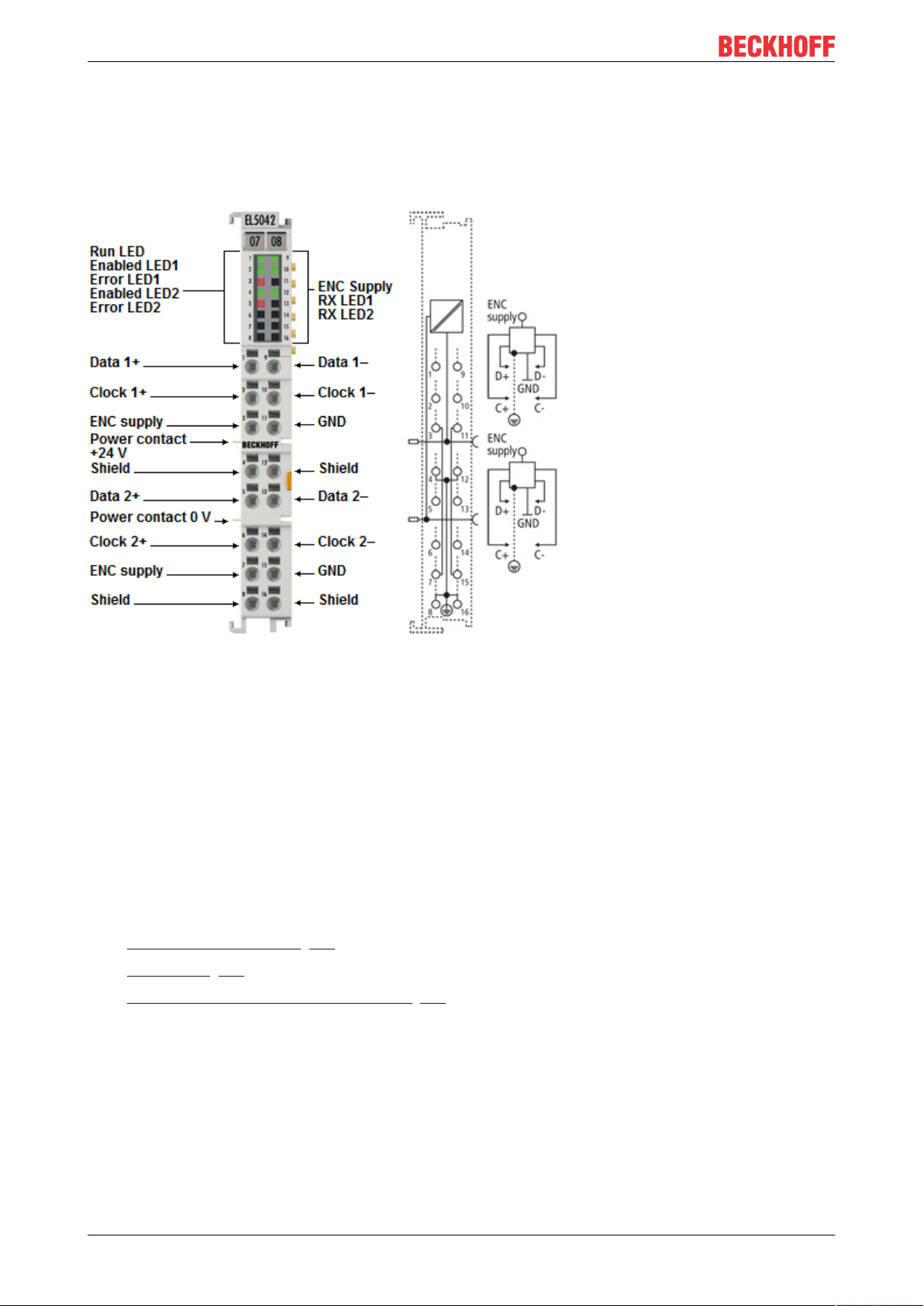
4.7 LEDs and connection
Fig.26: EL5042 - LEDs
NOTE
Possible damage of devices: Note encoder supply voltage!
Note the limit values for the supply voltage specified in the data sheets of the encoder manufacturers. The
encoder supply voltage may have to be adjusted in object 0x80p8:12 [}90] (5 V or 9 V)!
LEDs
LED Color Meaning
RUN (1) green This LED indicates the terminal's operating state:
off State of the EtherCAT State Machine: INIT=initialization of the
terminal
flashing State of the EtherCAT State Machine: PREOP = function for mailbox
communication and different standard-settings set
single flash State of the EtherCAT State Machine: SAFEOP = verification of the
sync manager channels and the distributed clocks. Outputs remain in
safe state
on State of the EtherCAT State Machine: OP = normal operating state;
mailbox and process data communication is possible
flickering State of the EtherCAT State Machine: BOOTSTRAP = function for
terminal firmware updates
ENABLED 1 (2)
ENABLED 2 (4)
ERROR 1 (3)
ERROR 2 (5)
ENC SUPPLY
(9)
RX 1 (10)
RX 2 (12)
green ON Connected encoder for the corresponding channel initialized and
ready for operation (Ready bit is set)
OFF Connected encoder for the corresponding channel not ready for
operation (Ready bit is not set)
red ON No encoder connected to the corresponding channel, or position
values invalid (TxPDO bit set)
OFF No error
green ON Encoder voltage present
OFF 24V field voltage missing or encoder voltage overload
green FLASHES Terminal receives position values at the corresponding channel
Connection
NOTE
Encoder supply via the terminal
The encoder supply voltage (5 V or 9 V), which can be set in object 0x80p8:12 [}90], can be taken from
the terminal points 3 (channel 1) and 7 (channel 2).
EL5042 39Version: 1.5
Page 40

Mounting and wiring
Terminal point Description
Name No.
Data 1+ 1 Data + input (channel 1)
Clock 1+ 2 Clock + input (channel 1)
5 V / 9 V 3 Supply voltage for encoder (+5V / +9V)
Shield 4 Shield
Data 2+ 5 Data + input (channel 2)
Clock 2+ 6 Clock + input (channel 2)
5 V / 9 V 7 Supply voltage for encoder (+5V / +9V)
Shield 8 Shield
Data 1- 9 Data - input (channel 1)
Clock 1- 10 Clock - input (channel 1)
GND 11 Ground
Shield 12 Shield
Data 2- 13 Data - input (channel 2)
Clock 2- 14 Clock - input (channel 2)
GND 15 Ground
Shield 16 Shield
Data transfer medium
The BiSS-C and also SSI information (Clock and Data) are transmitted as differential signals. To ensure a
good EMC immunity, also for long distances, shielded cables with twisted pair conductors should be used.
The cable shield should be connected to earth at both channel ends and the two end devices should be
always at the same reference potential. When using external shielded cables, particular care should be paid
not to damage or to interrupt the shield itself. Shield should be connected near by the connector. Refer also
to the corresponding notes of the sensor manufacturer.
The value of each termination resistor should be equal to the cable characteristic impedance, typically 120
ohms for EIA-422 or RS-422 standard.
EL504240 Version: 1.5
Page 41

Commissioning
5 Commissioning
5.1 Quick start
Proceed as follows for standard commissioning of the EL5042 with BiSS-C devices.
1. Install the EL5042 in the E-bus terminal strand on an EtherCAT coupler, e.g. EK1100 or EK1501.
2. Connect the BiSS-C device(s) according to the connection diagram (Data(+/-), Clock(+/-) and supply
voltage).
3. Set up a correct EtherCAT configuration with the terminal.
Since the device is present and is electrically reachable, the simplest way of accomplishing this is by
scanning the devices [}57].
4. Activate the EtherCAT master and start the terminal in OP state.
In the input variables the EL5042 must deliver State=8 and WC=0.
5. Parameterize the CoE settings of the EL5042 according to the BiSS-C device data sheet.
◦ Reverse any previous parameter changes by means of a CoE reset: enter 0x64616F6C inobject
0x1011:01 [}90].
◦ If an encoder voltage of, for example, 9 V is set in object 0x8008:1 [}90]2, ensure before
connecting that this is supported by both encoders.
6. The data can now be read via the process data.
5.2 TwinCAT Development Environment
The Software for automation TwinCAT (The Windows Control and Automation Technology) will be
distinguished into:
• TwinCAT2: System Manager (Configuration) & PLC Control (Programming)
• TwinCAT3: Enhancement of TwinCAT2 (Programming and Configuration takes place via a common
Development Environment)
Details:
• TwinCAT2:
◦ Connects I/O devices to tasks in a variable-oriented manner
◦ Connects tasks to tasks in a variable-oriented manner
◦ Supports units at the bit level
◦ Supports synchronous or asynchronous relationships
◦ Exchange of consistent data areas and process images
◦ Datalink on NT - Programs by open Microsoft Standards (OLE, OCX, ActiveX, DCOM+, etc.)
◦ Integration of IEC 61131-3-Software-SPS, Software- NC and Software-CNC within Windows
NT/2000/XP/Vista, Windows 7, NT/XP Embedded, CE
◦ Interconnection to all common fieldbusses
◦ More…
Additional features:
• TwinCAT3 (eXtended Automation):
◦ Visual-Studio®-Integration
◦ Choice of the programming language
◦ Supports object orientated extension of IEC 61131-3
◦ Usage of C/C++ as programming language for real time applications
◦ Connection to MATLAB®/Simulink®
EL5042 41Version: 1.5
Page 42
Commissioning
◦ Open interface for expandability
◦ Flexible run-time environment
◦ Active support of Multi-Core- und 64-Bit-Operatingsystem
◦ Automatic code generation and project creation with the TwinCAT Automation Interface
◦ More…
Within the following sections commissioning of the TwinCAT Development Environment on a PC System for
the control and also the basically functions of unique control elements will be explained.
Please see further information to TwinCAT2 and TwinCAT3 at http://infosys.beckhoff.com.
5.2.1 Installation of the TwinCAT real-time driver
In order to assign real-time capability to a standard Ethernet port of an IPC controller, the Beckhoff real-time
driver has to be installed on this port under Windows.
This can be done in several ways. One option is described here.
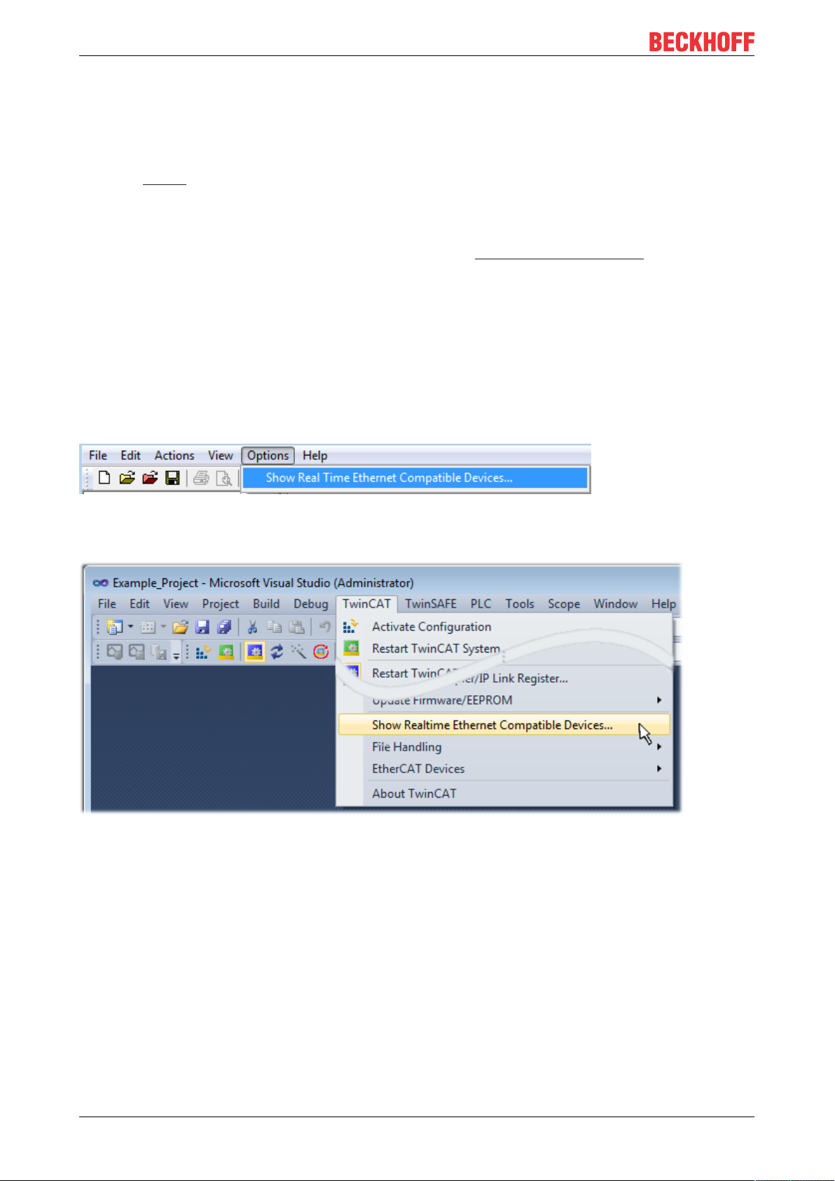
In the System Manager call up the TwinCAT overview of the local network interfaces via Options → Show
Real Time Ethernet Compatible Devices.
Fig.27: System Manager “Options” (TwinCAT2)
This have to be called up by the Menü “TwinCAT” within the TwinCAT3 environment:
Fig.28: Call up under VS Shell (TwinCAT3)
The following dialog appears:
EL504242 Version: 1.5
Page 43

Commissioning
Fig.29: Overview of network interfaces
Interfaces listed under “Compatible devices” can be assigned a driver via the “Install” button. A driver should
only be installed on compatible devices.
A Windows warning regarding the unsigned driver can be ignored.
Alternatively an EtherCAT-device can be inserted first of all as described in chapter Offline configuration
creation, section “Creating the EtherCAT device” [}52] in order to view the compatible ethernet ports via its
EtherCAT properties (tab „Adapter“, button „Compatible Devices…“):
Fig.30: EtherCAT device properties(TwinCAT2): click on „Compatible Devices…“ of tab “Adapter”
TwinCAT 3: the properties of the EtherCAT device can be opened by double click on “Device .. (EtherCAT)”
within the Solution Explorer under “I/O”:
After the installation the driver appears activated in the Windows overview for the network interface
(Windows Start → System Properties → Network)
EL5042 43Version: 1.5
Page 44

Commissioning
Fig.31: Windows properties of the network interface
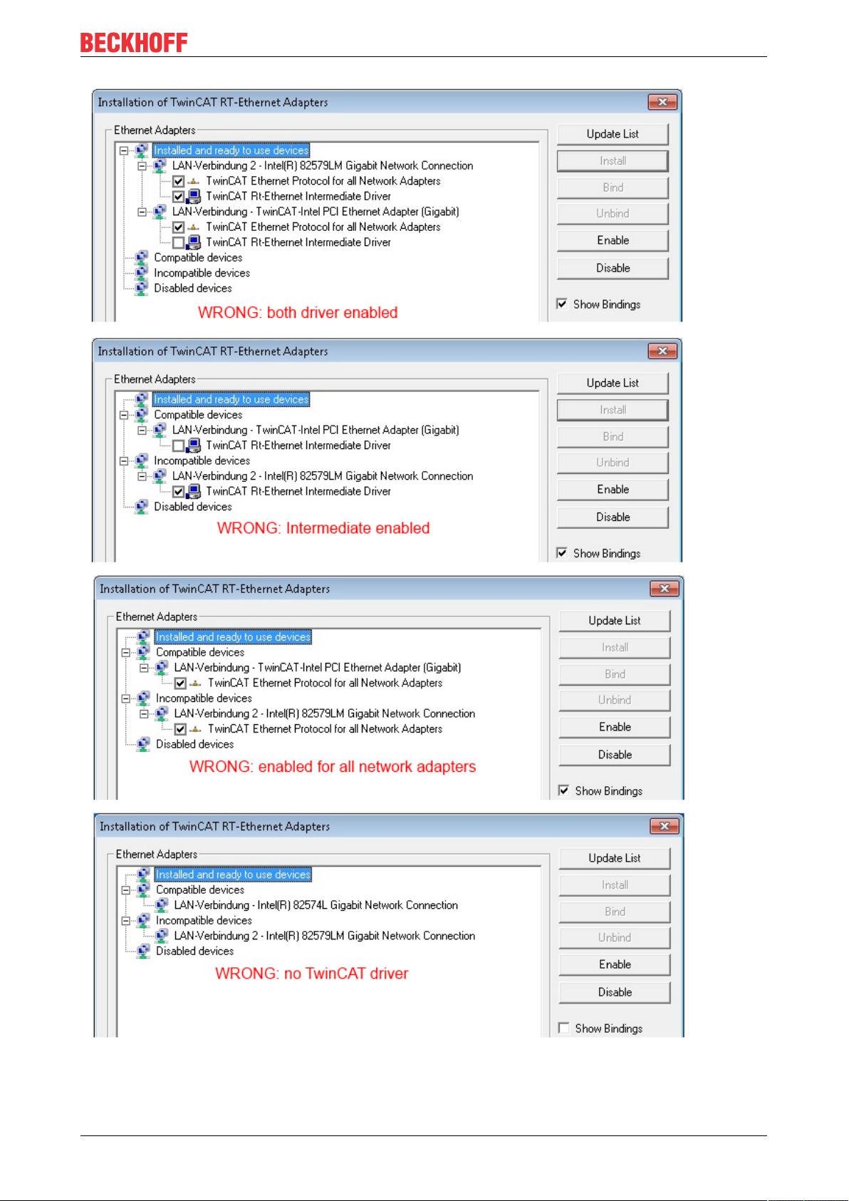
A correct setting of the driver could be:
Fig.32: Exemplary correct driver setting for the Ethernet port
Other possible settings have to be avoided:
EL504244 Version: 1.5
Page 45
Commissioning
Fig.33: Incorrect driver settings for the Ethernet port
EL5042 45Version: 1.5
Page 46
Commissioning
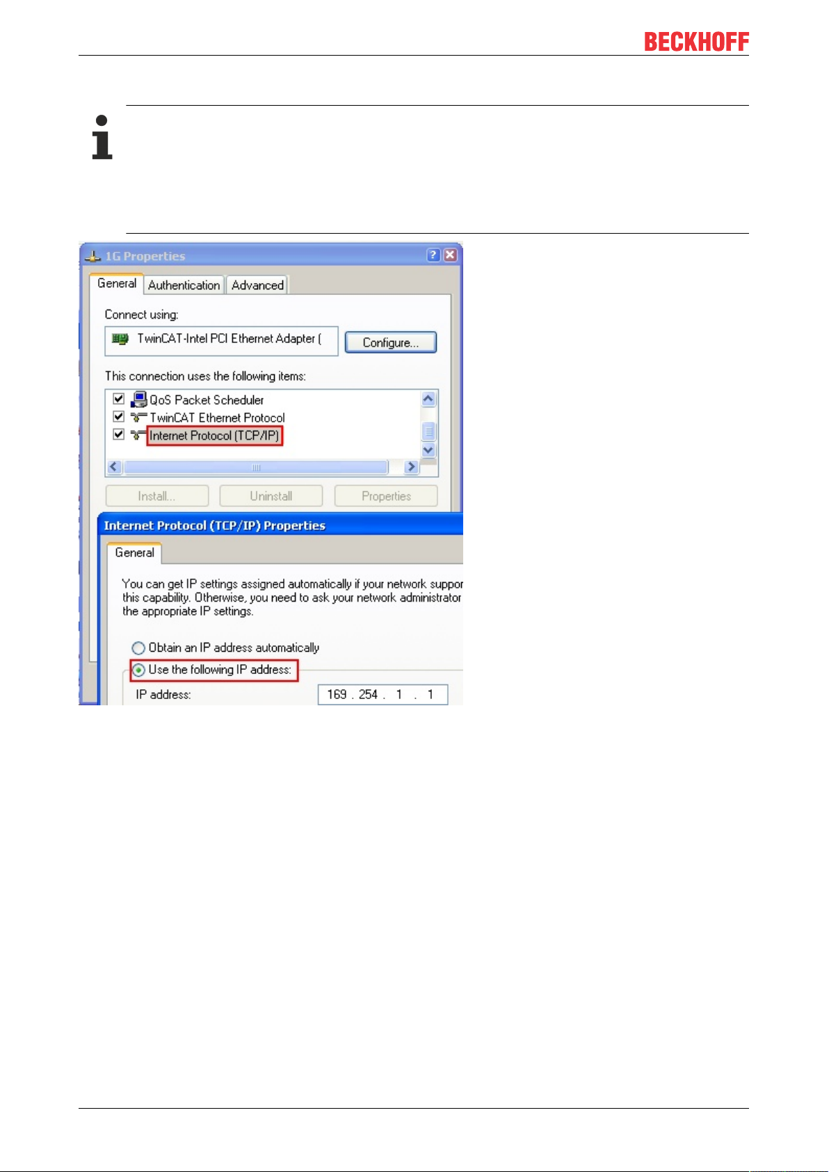
IP address of the port used
IP address/DHCP
In most cases an Ethernet port that is configured as an EtherCAT device will not transport general
IP packets. For this reason and in cases where an EL6601 or similar devices are used it is useful to
specify a fixed IP address for this port via the “Internet Protocol TCP/IP” driver setting and to disable
DHCP. In this way the delay associated with the DHCP client for the Ethernet port assigning itself a
default IP address in the absence of a DHCP server is avoided. A suitable address space is
192.168.x.x, for example.
Fig.34: TCP/IP setting for the Ethernet port
EL504246 Version: 1.5
Page 47

Commissioning
5.2.2 Notes regarding ESI device description
Installation of the latest ESI device description
The TwinCAT EtherCAT master/System Manager needs the device description files for the devices to be
used in order to generate the configuration in online or offline mode. The device descriptions are contained
in the so-called ESI files (EtherCAT Slave Information) in XML format. These files can be requested from the
respective manufacturer and are made available for download. An *.xml file may contain several device
descriptions.
The ESI files for Beckhoff EtherCAT devices are available on the Beckhoff website.
The ESI files should be stored in the TwinCAT installation directory.
Default settings:
• TwinCAT2: C:\TwinCAT\IO\EtherCAT
• TwinCAT3: C:\TwinCAT\3.1\Config\Io\EtherCAT
The files are read (once) when a new System Manager window is opened, if they have changed since the
last time the System Manager window was opened.
A TwinCAT installation includes the set of Beckhoff ESI files that was current at the time when the TwinCAT
build was created.
For TwinCAT2.11/TwinCAT3 and higher, the ESI directory can be updated from the System Manager, if the
programming PC is connected to the Internet; by
• TwinCAT2: Option → “Update EtherCAT Device Descriptions”
• TwinCAT3: TwinCAT → EtherCAT Devices → “Update Device Descriptions (via ETG Website)…”
The TwinCAT ESI Updater [}51] is available for this purpose.
ESI
The *.xml files are associated with *.xsd files, which describe the structure of the ESI XML files. To
update the ESI device descriptions, both file types should therefore be updated.
Device differentiation
EtherCAT devices/slaves are distinguished by four properties, which determine the full device identifier. For
example, the device identifier EL2521-0025-1018 consists of:
• family key “EL”
• name “2521”
• type “0025”
• and revision “1018”
Fig.35: Identifier structure
The order identifier consisting of name + type (here: EL2521-0010) describes the device function. The
revision indicates the technical progress and is managed by Beckhoff. In principle, a device with a higher
revision can replace a device with a lower revision, unless specified otherwise, e.g. in the documentation.
Each revision has its own ESI description. See further notes.
EL5042 47Version: 1.5
Page 48

Commissioning
Online description
If the EtherCAT configuration is created online through scanning of real devices (see section Online setup)
and no ESI descriptions are available for a slave (specified by name and revision) that was found, the
System Manager asks whether the description stored in the device should be used. In any case, the System
Manager needs this information for setting up the cyclic and acyclic communication with the slave correctly.
Fig.36: OnlineDescription information window (TwinCAT2)
In TwinCAT3 a similar window appears, which also offers the Web update:
Fig.37: Information window OnlineDescription (TwinCAT3)
If possible, the Yes is to be rejected and the required ESI is to be requested from the device manufacturer.
After installation of the XML/XSD file the configuration process should be repeated.
NOTE
Changing the ‘usual’ configuration through a scan
ü If a scan discovers a device that is not yet known to TwinCAT, distinction has to be made between two
cases. Taking the example here of the EL2521-0000 in the revision 1019
a) no ESI is present for the EL2521-0000 device at all, either for the revision 1019 or for an older revision.
The ESI must then be requested from the manufacturer (in this case Beckhoff).
b) an ESI is present for the EL2521-0000 device, but only in an older revision, e.g. 1018 or 1017.
In this case an in-house check should first be performed to determine whether the spare parts stock allows the integration of the increased revision into the configuration at all. A new/higher revision usually
also brings along new features. If these are not to be used, work can continue without reservations with
the previous revision 1018 in the configuration. This is also stated by the Beckhoff compatibility rule.
Refer in particular to the chapter ‘General notes on the use of Beckhoff EtherCAT IO components’ and for
manual configuration to the chapter ‘Offline configuration creation’ [}52].
If the OnlineDescription is used regardless, the System Manager reads a copy of the device description from
the EEPROM in the EtherCAT slave. In complex slaves the size of the EEPROM may not be sufficient for the
complete ESI, in which case the ESI would be incomplete in the configurator. Therefore it’s recommended
using an offline ESI file with priority in such a case.
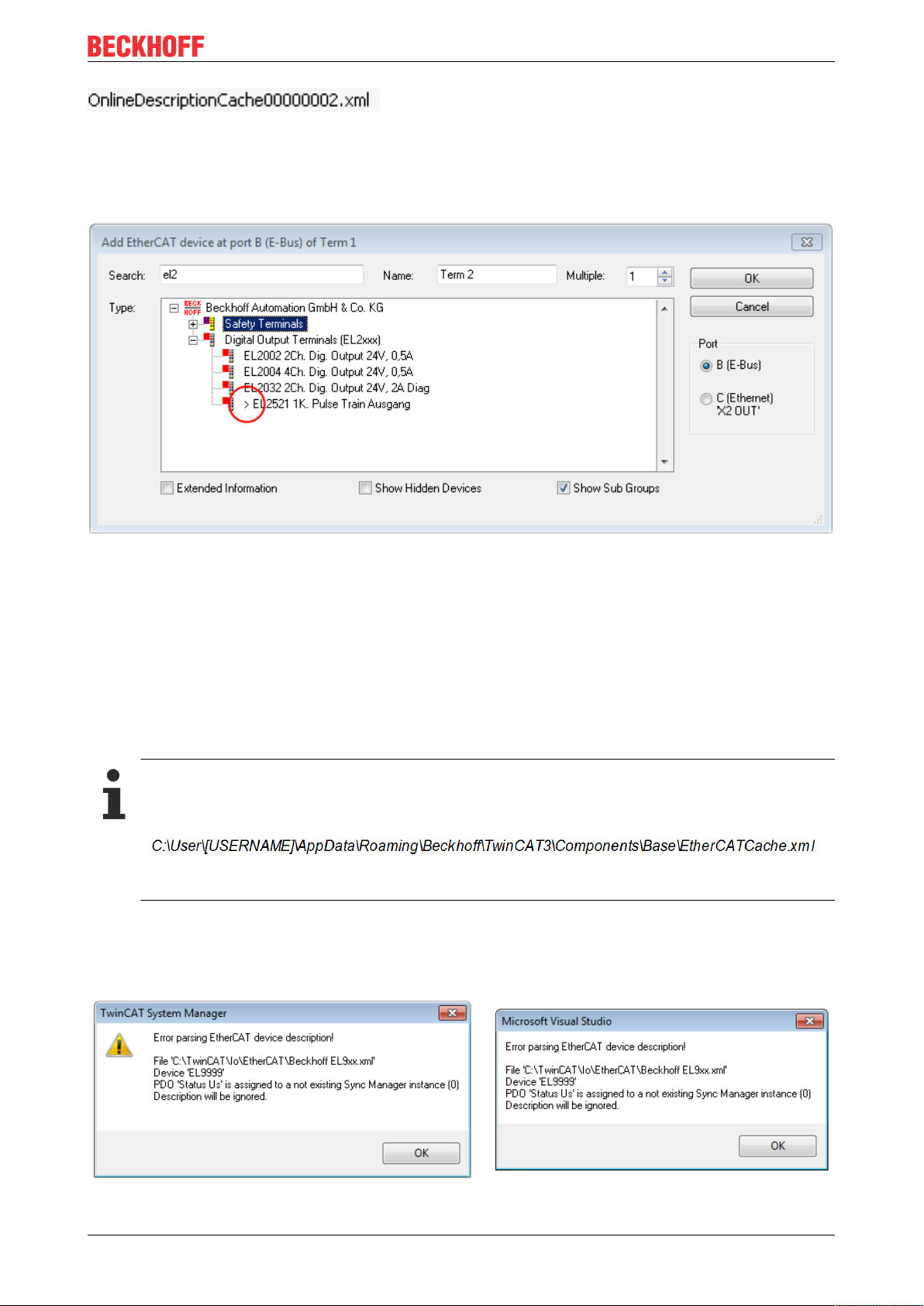
The System Manager creates for online recorded device descriptions a new file
“OnlineDescription0000...xml” in its ESI directory, which contains all ESI descriptions that were read online.
EL504248 Version: 1.5
Page 49
Commissioning
Fig.38: File OnlineDescription.xml created by the System Manager
Is a slave desired to be added manually to the configuration at a later stage, online created slaves are
indicated by a prepended symbol “>” in the selection list (see Figure “Indication of an online recorded ESI of
EL2521 as an example”).
Fig.39: Indication of an online recorded ESI of EL2521 as an example
If such ESI files are used and the manufacturer's files become available later, the file OnlineDescription.xml
should be deleted as follows:
• close all System Manager windows
• restart TwinCAT in Config mode
• delete "OnlineDescription0000...xml"
• restart TwinCAT System Manager
This file should not be visible after this procedure, if necessary press <F5> to update
OnlineDescription for TwinCAT3.x
In addition to the file described above "OnlineDescription0000...xml" , a so called EtherCAT cache
with new discovered devices is created by TwinCAT3.x, e.g. under Windows 7:
(Please note the language settings of the OS!)
You have to delete this file, too.
Faulty ESI file
If an ESI file is faulty and the System Manager is unable to read it, the System Manager brings up an
information window.
Fig.40: Information window for faulty ESI file (left: TwinCAT2; right: TwinCAT3)
EL5042 49Version: 1.5
Page 50

Commissioning
Reasons may include:
• Structure of the *.xml does not correspond to the associated *.xsd file → check your schematics
• Contents cannot be translated into a device description → contact the file manufacturer
EL504250 Version: 1.5
Page 51

Commissioning
5.2.3 TwinCAT ESI Updater
For TwinCAT2.11 and higher, the System Manager can search for current Beckhoff ESI files automatically, if
an online connection is available:
Fig.41: Using the ESI Updater (>= TwinCAT2.11)
The call up takes place under:
“Options” → "Update EtherCAT Device Descriptions"
Selection under TwinCAT3:
Fig.42: Using the ESI Updater (TwinCAT3)
The ESI Updater (TwinCAT3) is a convenient option for automatic downloading of ESI data provided by
EtherCAT manufacturers via the Internet into the TwinCAT directory (ESI = EtherCAT slave information).
TwinCAT accesses the central ESI ULR directory list stored at ETG; the entries can then be viewed in the
Updater dialog, although they cannot be changed there.
The call up takes place under:
“TwinCAT“ → „EtherCAT Devices“ → “Update Device Description (via ETG Website)…“.
5.2.4 Distinction between Online and Offline
The distinction between online and offline refers to the presence of the actual I/O environment (drives,
terminals, EJ-modules). If the configuration is to be prepared in advance of the system configuration as a
programming system, e.g. on a laptop, this is only possible in “Offline configuration” mode. In this case all
components have to be entered manually in the configuration, e.g. based on the electrical design.
If the designed control system is already connected to the EtherCAT system and all components are
energised and the infrastructure is ready for operation, the TwinCAT configuration can simply be generated
through “scanning” from the runtime system. This is referred to as online configuration.
In any case, during each startup the EtherCAT master checks whether the slaves it finds match the
configuration. This test can be parameterised in the extended slave settings. Refer to note “Installation of
the latest ESI-XML device description” [}47].
For preparation of a configuration:
• the real EtherCAT hardware (devices, couplers, drives) must be present and installed
• the devices/modules must be connected via EtherCAT cables or in the terminal/ module strand in the
same way as they are intended to be used later
EL5042 51Version: 1.5
Page 52

Commissioning
• the devices/modules be connected to the power supply and ready for communication
• TwinCAT must be in CONFIG mode on the target system.
The online scan process consists of:
• detecting the EtherCAT device [}57] (Ethernet port at the IPC)
• detecting the connected EtherCAT devices [}58]. This step can be carried out independent of the
preceding step
• troubleshooting [}61]
The scan with existing configuration [}62] can also be carried out for comparison.
5.2.5 OFFLINE configuration creation
Creating the EtherCAT device
Create an EtherCAT device in an empty System Manager window.
Fig.43: Append EtherCAT device (left: TwinCAT2; right: TwinCAT3)
Select type ‘EtherCAT’ for an EtherCAT I/O application with EtherCAT slaves. For the present publisher/
subscriber service in combination with an EL6601/EL6614 terminal select “EtherCAT Automation Protocol
via EL6601”.
Fig.44: Selecting the EtherCAT connection (TwinCAT2.11, TwinCAT3)
Then assign a real Ethernet port to this virtual device in the runtime system.
Fig.45: Selecting the Ethernet port
EL504252 Version: 1.5
Page 53

Commissioning
This query may appear automatically when the EtherCAT device is created, or the assignment can be set/
modified later in the properties dialog; see Fig. “EtherCAT device properties (TwinCAT2)”.
Fig.46: EtherCAT device properties (TwinCAT2)
TwinCAT 3: the properties of the EtherCAT device can be opened by double click on “Device .. (EtherCAT)”
within the Solution Explorer under “I/O”:
Selecting the Ethernet port
Ethernet ports can only be selected for EtherCAT devices for which the TwinCAT real-time driver is
installed. This has to be done separately for each port. Please refer to the respective installation
page [}42].
Defining EtherCAT slaves
Further devices can be appended by right-clicking on a device in the configuration tree.
Fig.47: Appending EtherCAT devices (left: TwinCAT2; right: TwinCAT3)
The dialog for selecting a new device opens. Only devices for which ESI files are available are displayed.
Only devices are offered for selection that can be appended to the previously selected device. Therefore the
physical layer available for this port is also displayed (Fig. “Selection dialog for new EtherCAT device”, A). In
the case of cable-based Fast-Ethernet physical layer with PHY transfer, then also only cable-based devices
are available, as shown in Fig. “Selection dialog for new EtherCAT device”. If the preceding device has
several free ports (e.g. EK1122 or EK1100), the required port can be selected on the right-hand side (A).
Overview of physical layer
• “Ethernet”: cable-based 100BASE-TX: EK couplers, EP boxes, devices with RJ45/M8/M12 connector
EL5042 53Version: 1.5
Page 54

Commissioning
• “E-Bus”: LVDS “terminal bus”, “EJ-module”: EL/ES terminals, various modular modules
The search field facilitates finding specific devices (since TwinCAT2.11 or TwinCAT3).
Fig.48: Selection dialog for new EtherCAT device
By default only the name/device type is used as selection criterion. For selecting a specific revision of the
device the revision can be displayed as “Extended Information”.
Fig.49: Display of device revision
In many cases several device revisions were created for historic or functional reasons, e.g. through
technological advancement. For simplification purposes (see Fig. “Selection dialog for new EtherCAT
device”) only the last (i.e. highest) revision and therefore the latest state of production is displayed in the
selection dialog for Beckhoff devices. To show all device revisions available in the system as ESI
descriptions tick the “Show Hidden Devices” check box, see Fig. “Display of previous revisions”.
EL504254 Version: 1.5
Page 55

Fig.50: Display of previous revisions
Device selection based on revision, compatibility
The ESI description also defines the process image, the communication type between master and
slave/device and the device functions, if applicable. The physical device (firmware, if available) has
to support the communication queries/settings of the master. This is backward compatible, i.e.
newer devices (higher revision) should be supported if the EtherCAT master addresses them as an
older revision. The following compatibility rule of thumb is to be assumed for Beckhoff EtherCAT
Terminals/ Boxes/ EJ-modules:
device revision in the system >= device revision in the configuration
This also enables subsequent replacement of devices without changing the configuration (different
specifications are possible for drives).
Commissioning
Example
If an EL2521-0025-1018 is specified in the configuration, an EL2521-0025-1018 or higher (-1019, -1020) can
be used in practice.
Fig.51: Name/revision of the terminal
If current ESI descriptions are available in the TwinCAT system, the last revision offered in the selection
dialog matches the Beckhoff state of production. It is recommended to use the last device revision when
creating a new configuration, if current Beckhoff devices are used in the real application. Older revisions
should only be used if older devices from stock are to be used in the application.
In this case the process image of the device is shown in the configuration tree and can be parameterised as
follows: linking with the task, CoE/DC settings, plug-in definition, startup settings, ...
EL5042 55Version: 1.5
Page 56
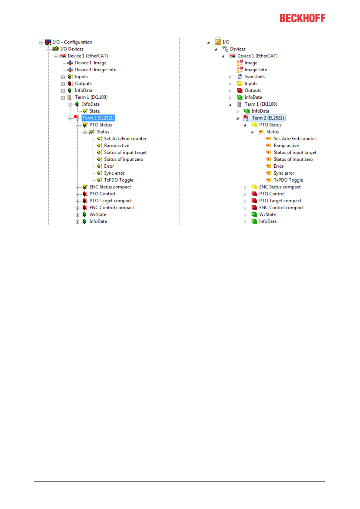
Commissioning
Fig.52: EtherCAT terminal in the TwinCAT tree (left: TwinCAT2; right: TwinCAT3)
EL504256 Version: 1.5
Page 57
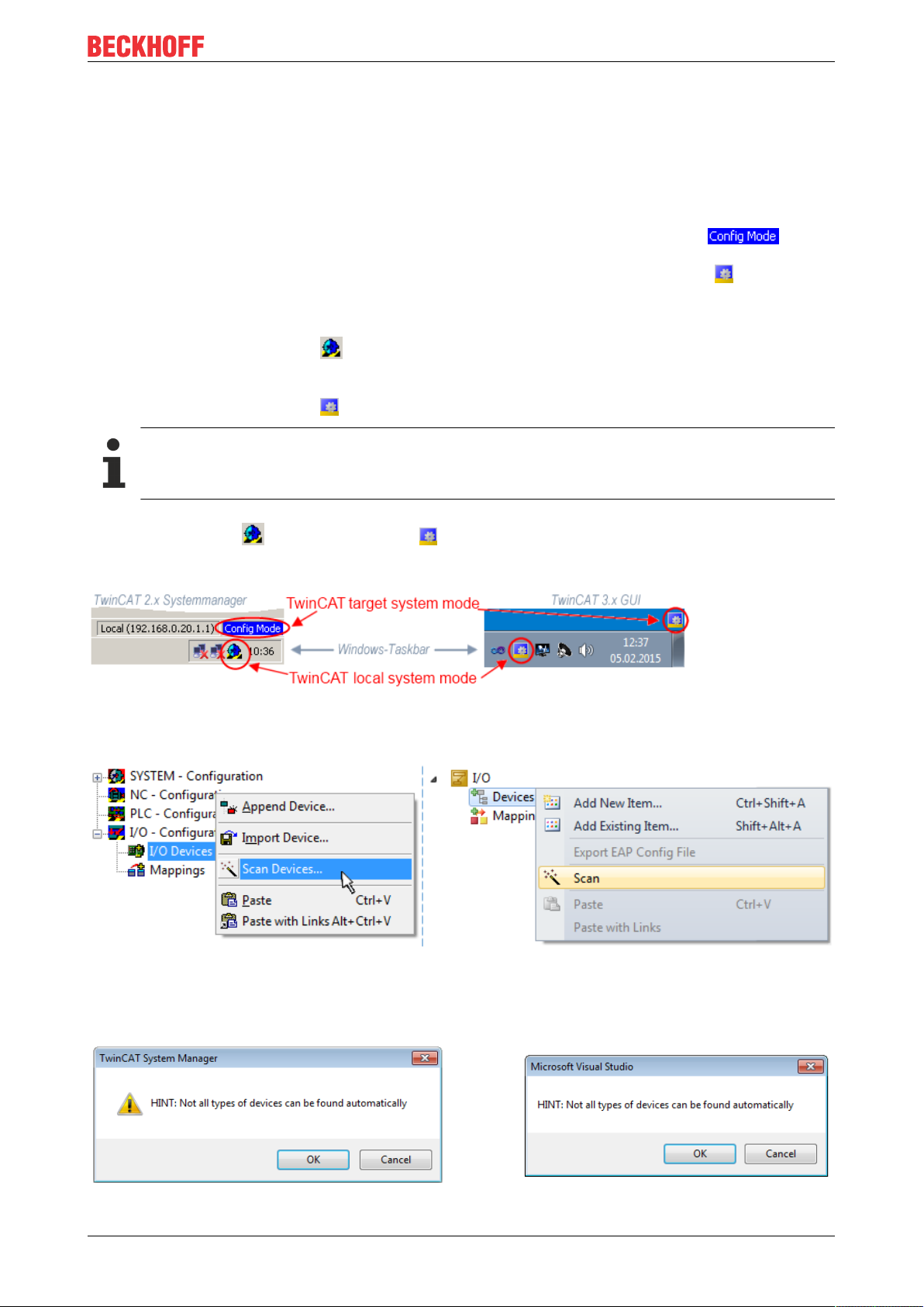
Commissioning
5.2.6 ONLINE configuration creation
Detecting/scanning of the EtherCAT device
The online device search can be used if the TwinCAT system is in CONFIG mode. This can be indicated by
a symbol right below in the information bar:
• on TwinCAT2 by a blue display “Config Mode” within the System Manager window: .
• on TwinCAT3 within the user interface of the development environment by a symbol .
TwinCAT can be set into this mode:
• TwinCAT2: by selection of in the Menubar or by “Actions” → “Set/Reset TwinCATtoConfig
Mode…”
• TwinCAT3: by selection of in the Menubar or by „TwinCAT“ → “RestartTwinCAT(ConfigMode)“
Online scanning in Config mode
The online search is not available in RUN mode (production operation). Note the differentiation between TwinCAT programming system and TwinCAT target system.
The TwinCAT2 icon ( ) or TwinCAT3 icon ( ) within the Windows-Taskbar always shows the
TwinCAT mode of the local IPC. Compared to that, the System Manager window of TwinCAT2 or the user
interface of TwinCAT3 indicates the state of the target system.
Fig.53: Differentiation local/target system (left: TwinCAT2; right: TwinCAT3)
Right-clicking on “I/O Devices” in the configuration tree opens the search dialog.
Fig.54: Scan Devices (left: TwinCAT2; right: TwinCAT3)
This scan mode attempts to find not only EtherCAT devices (or Ethernet ports that are usable as such), but
also NOVRAM, fieldbus cards, SMB etc. However, not all devices can be found automatically.
Fig.55: Note for automatic device scan (left: TwinCAT2; right: TwinCAT3)
EL5042 57Version: 1.5
Page 58

Commissioning
Ethernet ports with installed TwinCAT real-time driver are shown as “RT Ethernet” devices. An EtherCAT
frame is sent to these ports for testing purposes. If the scan agent detects from the response that an
EtherCAT slave is connected, the port is immediately shown as an “EtherCAT Device” .
Fig.56: Detected Ethernet devices
Via respective checkboxes devices can be selected (as illustrated in Fig. “Detected Ethernet devices” e.g.
Device 3 and Device 4 were chosen). After confirmation with “OK” a device scan is suggested for all selected
devices, see Fig.: “Scan query after automatic creation of an EtherCAT device”.
Selecting the Ethernet port
Ethernet ports can only be selected for EtherCAT devices for which the TwinCAT real-time driver is
installed. This has to be done separately for each port. Please refer to the respective installation
page [}42].
Detecting/Scanning the EtherCAT devices
Online scan functionality
During a scan the master queries the identity information of the EtherCAT slaves from the slave
EEPROM. The name and revision are used for determining the type. The respective devices are located in the stored ESI data and integrated in the configuration tree in the default state defined
there.
Fig.57: Example default state
NOTE
Slave scanning in practice in series machine production
The scanning function should be used with care. It is a practical and fast tool for creating an initial configuration as a basis for commissioning. In series machine production or reproduction of the plant, however, the
function should no longer be used for the creation of the configuration, but if necessary for comparison
[}62] with the defined initial configuration.Background: since Beckhoff occasionally increases the revision
version of the delivered products for product maintenance reasons, a configuration can be created by such
a scan which (with an identical machine construction) is identical according to the device list; however, the
respective device revision may differ from the initial configuration.
Example:
Company A builds the prototype of a machine B, which is to be produced in series later on. To do this the
prototype is built, a scan of the IO devices is performed in TwinCAT and the initial configuration ‘B.tsm’ is
created. The EL2521-0025 EtherCAT terminal with the revision 1018 is located somewhere. It is thus built
into the TwinCAT configuration in this way:
EL504258 Version: 1.5
Page 59

Commissioning
Fig.58: Installing EthetCAT terminal with revision -1018
Likewise, during the prototype test phase, the functions and properties of this terminal are tested by the
programmers/commissioning engineers and used if necessary, i.e. addressed from the PLC ‘B.pro’ or the
NC. (the same applies correspondingly to the TwinCAT3 solution files).
The prototype development is now completed and series production of machine B starts, for which Beckhoff
continues to supply the EL2521-0025-0018. If the commissioning engineers of the series machine production
department always carry out a scan, a B configuration with the identical contents results again for each
machine. Likewise, A might create spare parts stores worldwide for the coming series-produced machines
with EL2521-0025-1018 terminals.
After some time Beckhoff extends the EL2521-0025 by a new feature C. Therefore the FW is changed,
outwardly recognizable by a higher FW version and a new revision -1019. Nevertheless the new device
naturally supports functions and interfaces of the predecessor version(s); an adaptation of ‘B.tsm’ or even
‘B.pro’ is therefore unnecessary. The series-produced machines can continue to be built with ‘B.tsm’ and
‘B.pro’; it makes sense to perform a comparative scan [}62] against the initial configuration ‘B.tsm’ in order
to check the built machine.
However, if the series machine production department now doesn’t use ‘B.tsm’, but instead carries out a
scan to create the productive configuration, the revision -1019 is automatically detected and built into the
configuration:
Fig.59: Detection of EtherCAT terminal with revision -1019
This is usually not noticed by the commissioning engineers. TwinCAT cannot signal anything either, since
virtually a new configuration is created. According to the compatibility rule, however, this means that no
EL2521-0025-1018 should be built into this machine as a spare part (even if this nevertheless works in the
vast majority of cases).
In addition, it could be the case that, due to the development accompanying production in company A, the
new feature C of the EL2521-0025-1019 (for example, an improved analog filter or an additional process
data for the diagnosis) is discovered and used without in-house consultation. The previous stock of spare
part devices are then no longer to be used for the new configuration ‘B2.tsm’ created in this way.Þ if series
machine production is established, the scan should only be performed for informative purposes for
comparison with a defined initial configuration. Changes are to be made with care!
If an EtherCAT device was created in the configuration (manually or through a scan), the I/O field can be
scanned for devices/slaves.
Fig.60: Scan query after automatic creation of an EtherCAT device (left: TwinCAT2; right: TwinCAT3)
EL5042 59Version: 1.5
Page 60
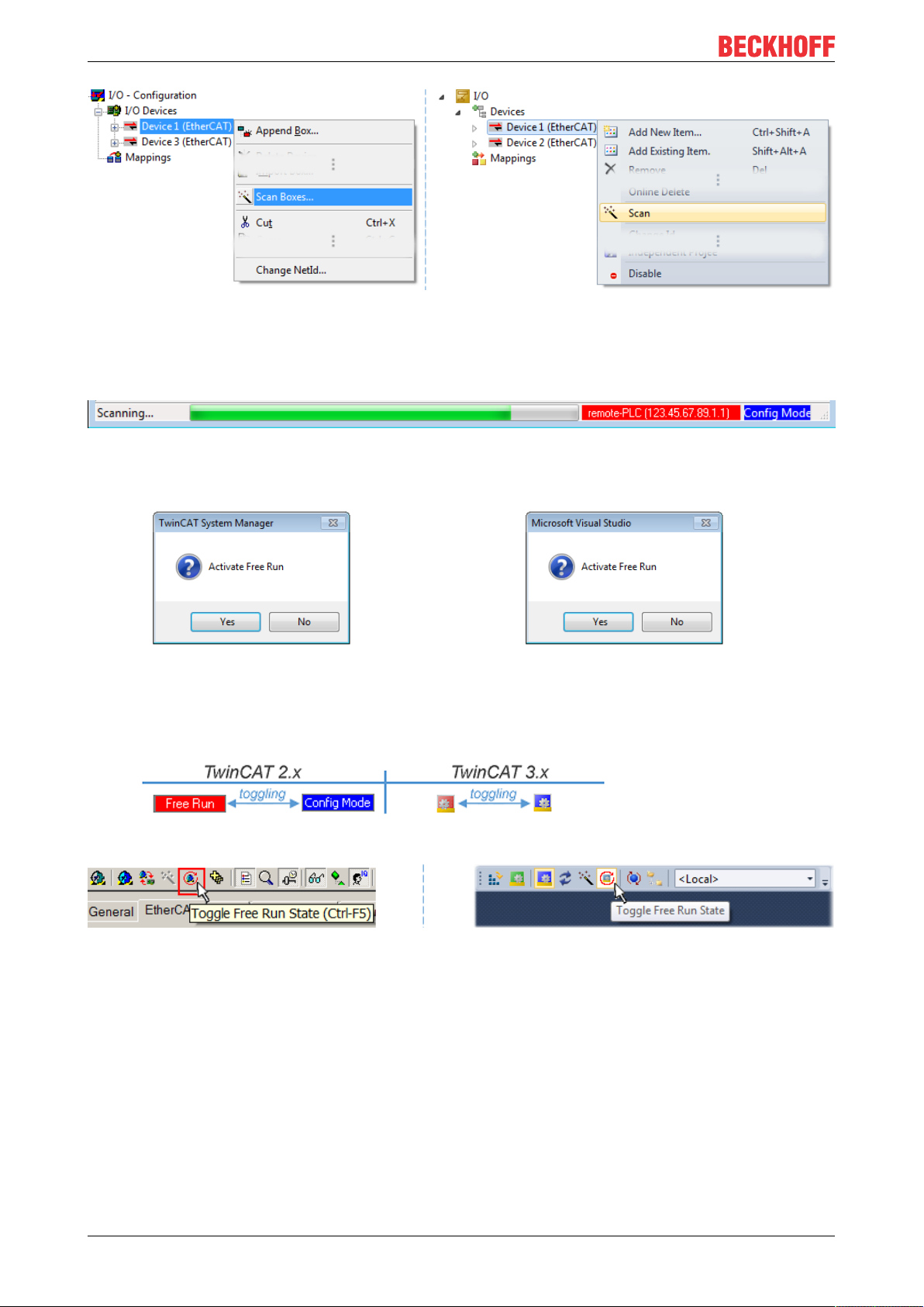
Commissioning
Fig.61: Manual triggering of a device scan on a specified EtherCAT device (left: TwinCAT2; right:
TwinCAT3)
In the System Manager (TwinCAT2) or the User Interface (TwinCAT3) the scan process can be monitored
via the progress bar at the bottom in the status bar.
Fig.62: Scan progressexemplary by TwinCAT2
The configuration is established and can then be switched to online state (OPERATIONAL).
Fig.63: Config/FreeRun query (left: TwinCAT2; right: TwinCAT3)
In Config/FreeRun mode the System Manager display alternates between blue and red, and the EtherCAT
device continues to operate with the idling cycle time of 4 ms (default setting), even without active task (NC,
PLC).
Fig.64: Displaying of “Free Run” and “Config Mode” toggling right below in the status bar
Fig.65: TwinCAT can also be switched to this state by using a button (left: TwinCAT2; right: TwinCAT3)
The EtherCAT system should then be in a functional cyclic state, as shown in Fig. “Online display example”.
EL504260 Version: 1.5
Page 61
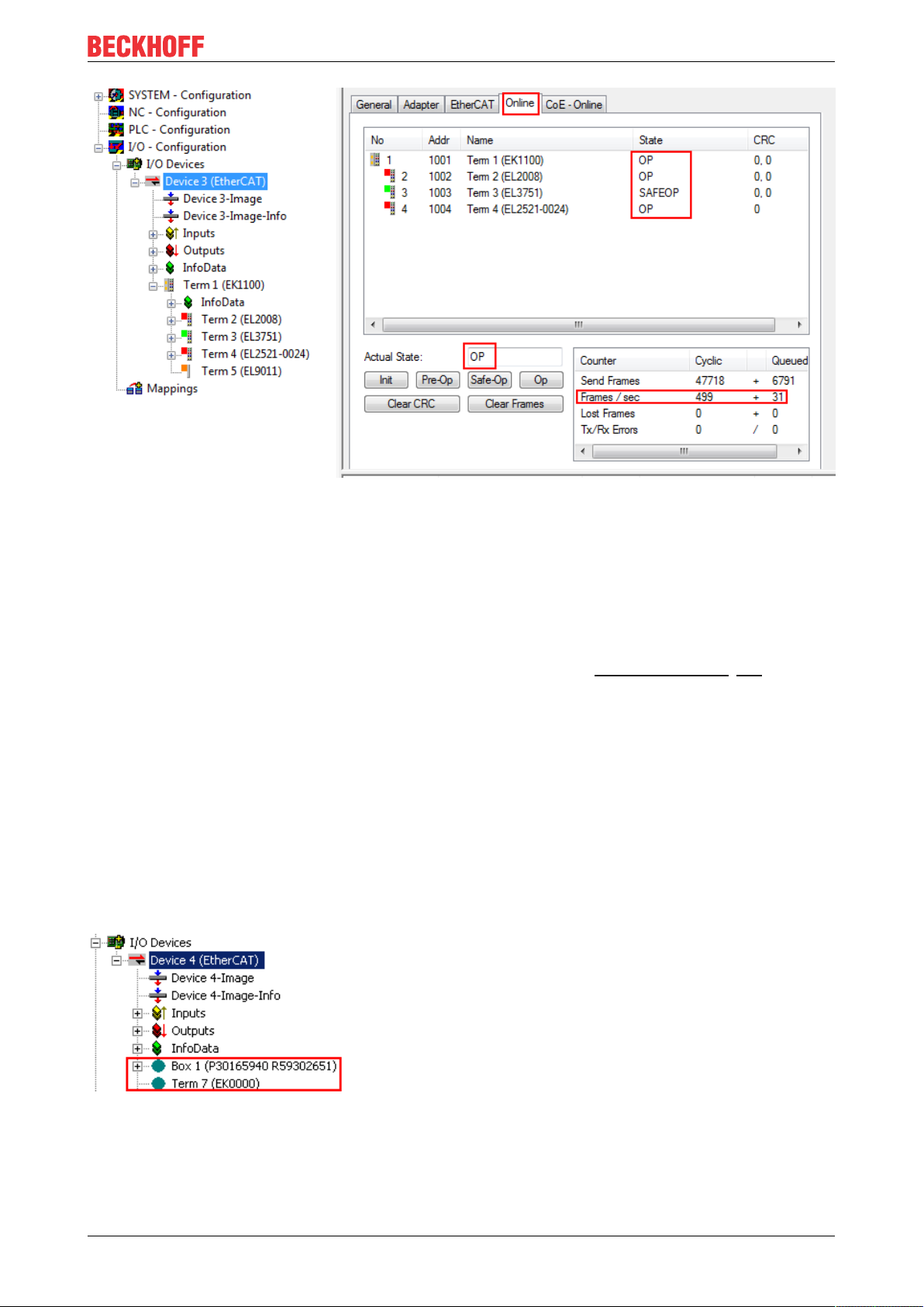
Commissioning
Fig.66: Online display example
Please note:
• all slaves should be in OP state
• the EtherCAT master should be in “Actual State” OP
• “frames/sec” should match the cycle time taking into account the sent number of frames
• no excessive “LostFrames” or CRC errors should occur
The configuration is now complete. It can be modified as described under manual procedure [}52].
Troubleshooting
Various effects may occur during scanning.
• An unknown device is detected, i.e. an EtherCAT slave for which no ESI XML description is available.
In this case the System Manager offers to read any ESI that may be stored in the device. This case is
described in the chapter "Notes regarding ESI device description".
• Device are not detected properly
Possible reasons include:
- faulty data links, resulting in data loss during the scan
- slave has invalid device description
The connections and devices should be checked in a targeted manner, e.g. via the emergency scan.
Then re-run the scan.
Fig.67: Faulty identification
In the System Manager such devices may be set up as EK0000 or unknown devices. Operation is not
possible or meaningful.
EL5042 61Version: 1.5
Page 62

Commissioning
Scan over existing Configuration
NOTE
Change of the configuration after comparison
With this scan (TwinCAT2.11 or 3.1) only the device properties vendor (manufacturer), device name and
revision are compared at present! A ‘ChangeTo’ or ‘Copy’ should only be carried out with care, taking into
consideration the Beckhoff IO compatibility rule (see above). The device configuration is then replaced by
the revision found; this can affect the supported process data and functions.
If a scan is initiated for an existing configuration, the actual I/O environment may match the configuration
exactly or it may differ. This enables the configuration to be compared.
Fig.68: Identical configuration (left: TwinCAT2; right: TwinCAT3)
If differences are detected, they are shown in the correction dialog, so that the user can modify the
configuration as required.
Fig.69: Correction dialog
It is advisable to tick the “Extended Information” check box to reveal differences in the revision.
EL504262 Version: 1.5
Page 63

Commissioning
Color Explanation
green This EtherCAT slave matches the entry on the other side. Both type and revision match.
blue This EtherCAT slave is present on the other side, but in a different revision. This other revision can
have other default values for the process data as well as other/additional functions.
If the found revision is higher than the configured revision, the slave may be used provided
compatibility issues are taken into account.
If the found revision is lower than the configured revision, it is likely that the slave cannot be used.
The found device may not support all functions that the master expects based on the higher
revision number.
light
blue
red • This EtherCAT slave is not present on the other side.
This EtherCAT slave is ignored (“Ignore” button)
• It is present, but in a different revision, which also differs in its properties from the one specified.
The compatibility principle then also applies here: if the found revision is higher than the
configured revision, use is possible provided compatibility issues are taken into account, since
the successor devices should support the functions of the predecessor devices.
If the found revision is lower than the configured revision, it is likely that the slave cannot be
used. The found device may not support all functions that the master expects based on the
higher revision number.
Device selection based on revision, compatibility
The ESI description also defines the process image, the communication type between master and
slave/device and the device functions, if applicable. The physical device (firmware, if available) has
to support the communication queries/settings of the master. This is backward compatible, i.e.
newer devices (higher revision) should be supported if the EtherCAT master addresses them as an
older revision. The following compatibility rule of thumb is to be assumed for Beckhoff EtherCAT
Terminals/ Boxes/ EJ-modules:
device revision in the system >= device revision in the configuration
This also enables subsequent replacement of devices without changing the configuration (different
specifications are possible for drives).
Example
If an EL2521-0025-1018 is specified in the configuration, an EL2521-0025-1018 or higher (-1019, -1020) can
be used in practice.
Fig.70: Name/revision of the terminal
If current ESI descriptions are available in the TwinCAT system, the last revision offered in the selection
dialog matches the Beckhoff state of production. It is recommended to use the last device revision when
creating a new configuration, if current Beckhoff devices are used in the real application. Older revisions
should only be used if older devices from stock are to be used in the application.
In this case the process image of the device is shown in the configuration tree and can be parameterised as
follows: linking with the task, CoE/DC settings, plug-in definition, startup settings, ...
EL5042 63Version: 1.5
Page 64

Commissioning
Fig.71: Correction dialog with modifications
Once all modifications have been saved or accepted, click “OK” to transfer them to the real *.tsm
configuration.
Change to Compatible Type
TwinCAT offers a function “Change to Compatible Type…” for the exchange of a device whilst retaining the
links in the task.
Fig.72: Dialog “Change to Compatible Type…” (left: TwinCAT2; right: TwinCAT3)
This function is preferably to be used on AX5000 devices.
Change to Alternative Type
The TwinCAT System Manager offers a function for the exchange of a device: Change to Alternative Type
Fig.73: TwinCAT2 Dialog Change to Alternative Type
EL504264 Version: 1.5
Page 65
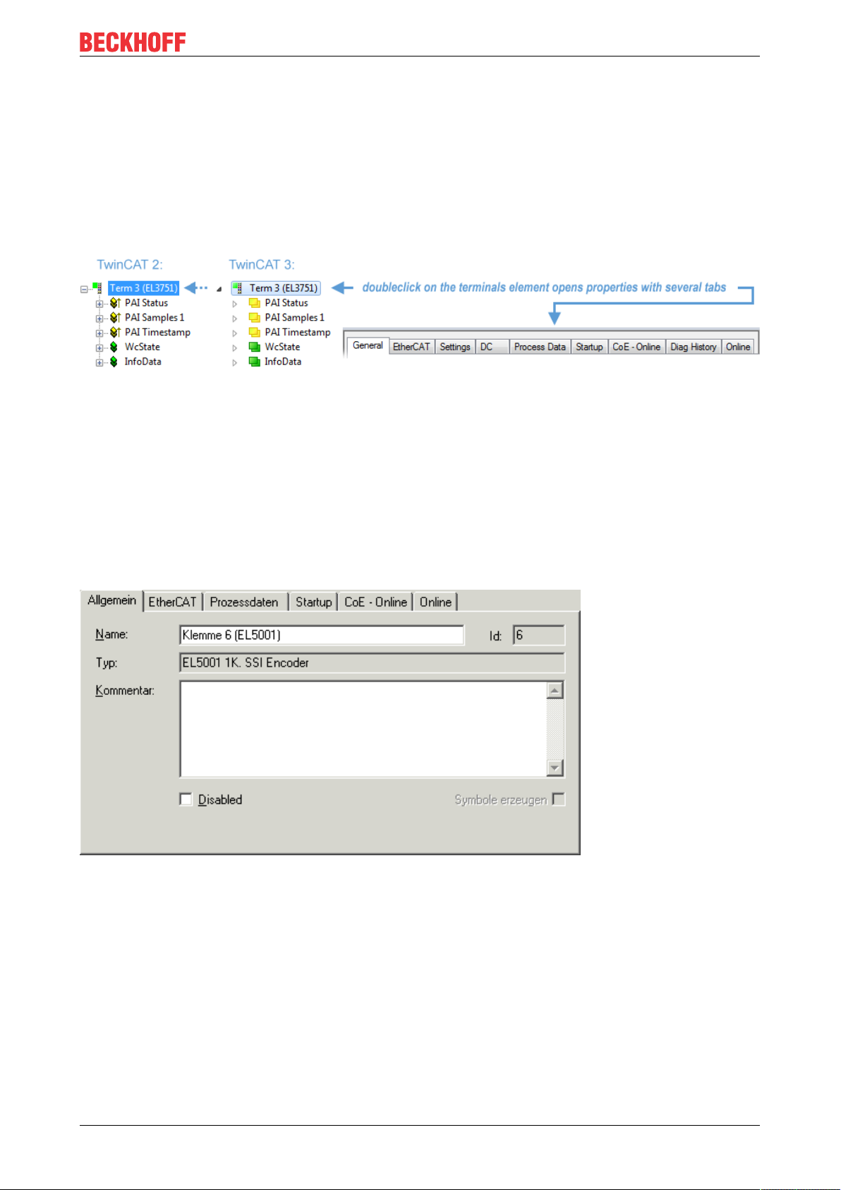
Commissioning
If called, the System Manager searches in the procured device ESI (in this example: EL1202-0000) for
details of compatible devices contained there. The configuration is changed and the ESI-EEPROM is
overwritten at the same time – therefore this process is possible only in the online state (ConfigMode).
5.2.7 EtherCAT subscriber configuration
In the left-hand window of the TwinCAT2 System Manager or the Solution Explorer of the TwinCAT3
Development Environment respectively, click on the element of the terminal within the tree you wish to
configure (in the example: EL3751 Terminal 3).
Fig.74: Branch element as terminal EL3751
In the right-hand window of the TwinCAT System manager (TwinCAT2) or the Development Environment
(TwinCAT3), various tabs are now available for configuring the terminal. And yet the dimension of
complexity of a subscriber determines which tabs are provided. Thus as illustrated in the example above the
terminal EL3751 provides many setup options and also a respective number of tabs are available. On the
contrary by the terminal EL1004 for example the tabs "General", "EtherCAT", "Process Data" and “Online“
are available only. Several terminals, as for instance the EL6695 provide special functions by a tab with its
own terminal name, so “EL6695” in this case. A specific tab “Settings” by terminals with a wide range of
setup options will be provided also (e.g. EL3751).
„General“ tab
Fig.75: “General” tab
Name Name of the EtherCAT device
Id Number of the EtherCAT device
Type EtherCAT device type
Comment Here you can add a comment (e.g. regarding the
system).
Disabled Here you can deactivate the EtherCAT device.
Create symbols Access to this EtherCAT slave via ADS is only
available if this control box is activated.
EL5042 65Version: 1.5
Page 66

Commissioning
„EtherCAT“ tab
Fig.76: „EtherCAT“ tab
Type EtherCAT device type
Product/Revision Product and revision number of the EtherCAT device
Auto Inc Addr. Auto increment address of the EtherCAT device. The
auto increment address can be used for addressing
each EtherCAT device in the communication ring
through its physical position. Auto increment
addressing is used during the start-up phase when
the EtherCAT master allocates addresses to the
EtherCAT devices. With auto increment addressing
the first EtherCAT slave in the ring has the address
0000
decremented by 1 (FFFF
. For each further slave the address is
hex
, FFFE
hex
hex
etc.).
EtherCAT Addr. Fixed address of an EtherCAT slave. This address is
allocated by the EtherCAT master during the start-up
phase. Tick the control box to the left of the input field
in order to modify the default value.
Previous Port Name and port of the EtherCAT device to which this
device is connected. If it is possible to connect this
device with another one without changing the order of
the EtherCAT devices in the communication ring,
then this combination field is activated and the
EtherCAT device to which this device is to be
connected can be selected.
Advanced Settings This button opens the dialogs for advanced settings.
The link at the bottom of the tab points to the product page for this EtherCAT device on the web.
“Process Data” tab
Indicates the configuration of the process data. The input and output data of the EtherCAT slave are
represented as CANopen process data objects (Process Data Objects, PDOs). The user can select a PDO
via PDO assignment and modify the content of the individual PDO via this dialog, if the EtherCAT slave
supports this function.
EL504266 Version: 1.5
Page 67

Fig.77: “Process Data” tab
Commissioning
The process data (PDOs) transferred by an EtherCAT slave during each cycle are user data which the
application expects to be updated cyclically or which are sent to the slave. To this end the EtherCAT master
(Beckhoff TwinCAT) parameterizes each EtherCAT slave during the start-up phase to define which process
data (size in bits/bytes, source location, transmission type) it wants to transfer to or from this slave. Incorrect
configuration can prevent successful start-up of the slave.
For Beckhoff EtherCAT EL, ES, EM, EJ and EP slaves the following applies in general:
• The input/output process data supported by the device are defined by the manufacturer in the ESI/XML
description. The TwinCAT EtherCAT Master uses the ESI description to configure the slave correctly.
• The process data can be modified in the system manager. See the device documentation.
Examples of modifications include: mask out a channel, displaying additional cyclic information, 16-bit
display instead of 8-bit data size, etc.
• In so-called “intelligent” EtherCAT devices the process data information is also stored in the CoE
directory. Any changes in the CoE directory that lead to different PDO settings prevent successful
startup of the slave. It is not advisable to deviate from the designated process data, because the
device firmware (if available) is adapted to these PDO combinations.
If the device documentation allows modification of process data, proceed as follows (see Figure “Configuring
the process data”).
• A: select the device to configure
• B: in the “Process Data” tab select Input or Output under SyncManager (C)
• D: the PDOs can be selected or deselected
• H: the new process data are visible as linkable variables in the system manager
The new process data are active once the configuration has been activated and TwinCAT has been
restarted (or the EtherCAT master has been restarted)
• E: if a slave supports this, Input and Output PDO can be modified simultaneously by selecting a socalled PDO record (“predefined PDO settings”).
EL5042 67Version: 1.5
Page 68
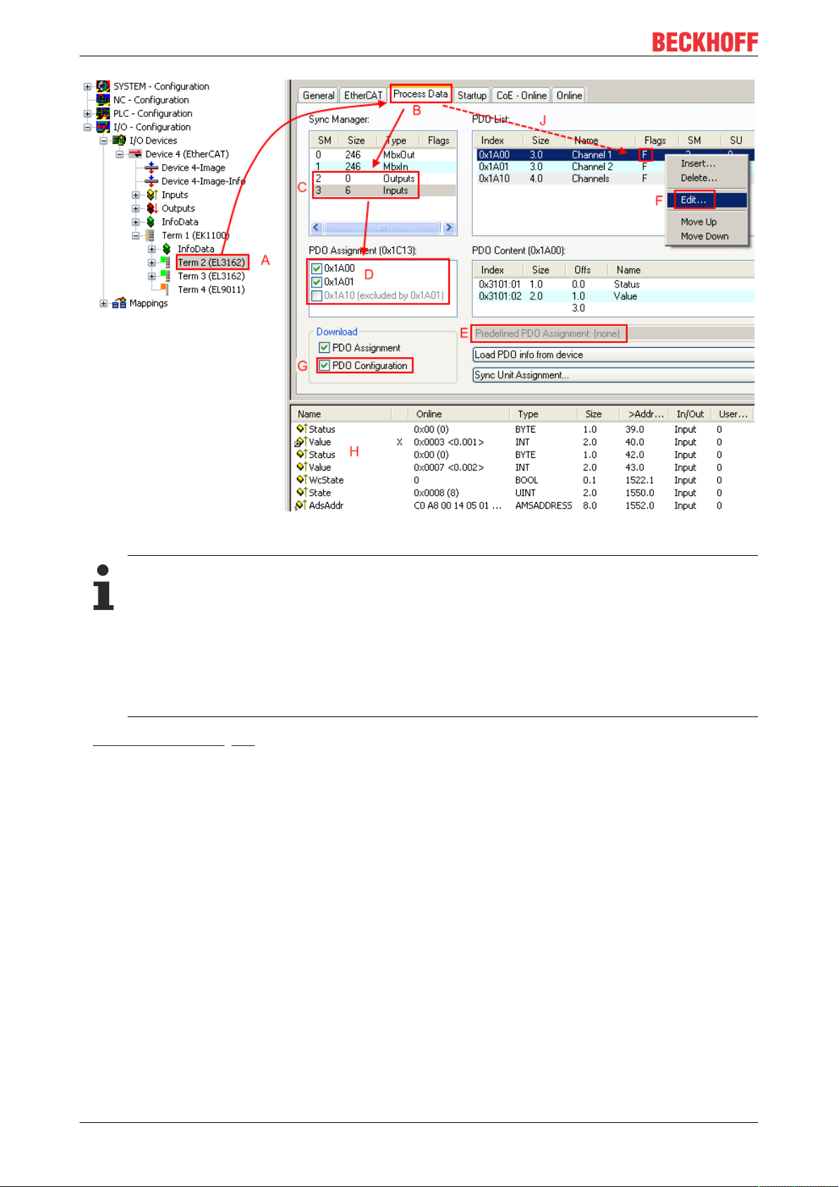
Commissioning
Fig.78: Configuring the process data
Manual modification of the process data
According to the ESI description, a PDO can be identified as “fixed” with the flag “F” in the PDO
overview (Fig. “Configuring the process data”, J). The configuration of such PDOs cannot be
changed, even if TwinCAT offers the associated dialog (“Edit”). In particular, CoE content cannot be
displayed as cyclic process data. This generally also applies in cases where a device supports
download of the PDO configuration, “G”. In case of incorrect configuration the EtherCAT slave usually refuses to start and change to OP state. The System Manager displays an “invalid SM cfg” logger message: This error message (“invalid SM IN cfg” or “invalid SM OUT cfg”) also indicates the
reason for the failed start.
A detailed description [}73] can be found at the end of this section.
„Startup“ tab
The Startup tab is displayed if the EtherCAT slave has a mailbox and supports the CANopen over EtherCAT
(CoE) or Servo drive over EtherCAT protocol. This tab indicates which download requests are sent to the
mailbox during startup. It is also possible to add new mailbox requests to the list display. The download
requests are sent to the slave in the same order as they are shown in the list.
EL504268 Version: 1.5
Page 69
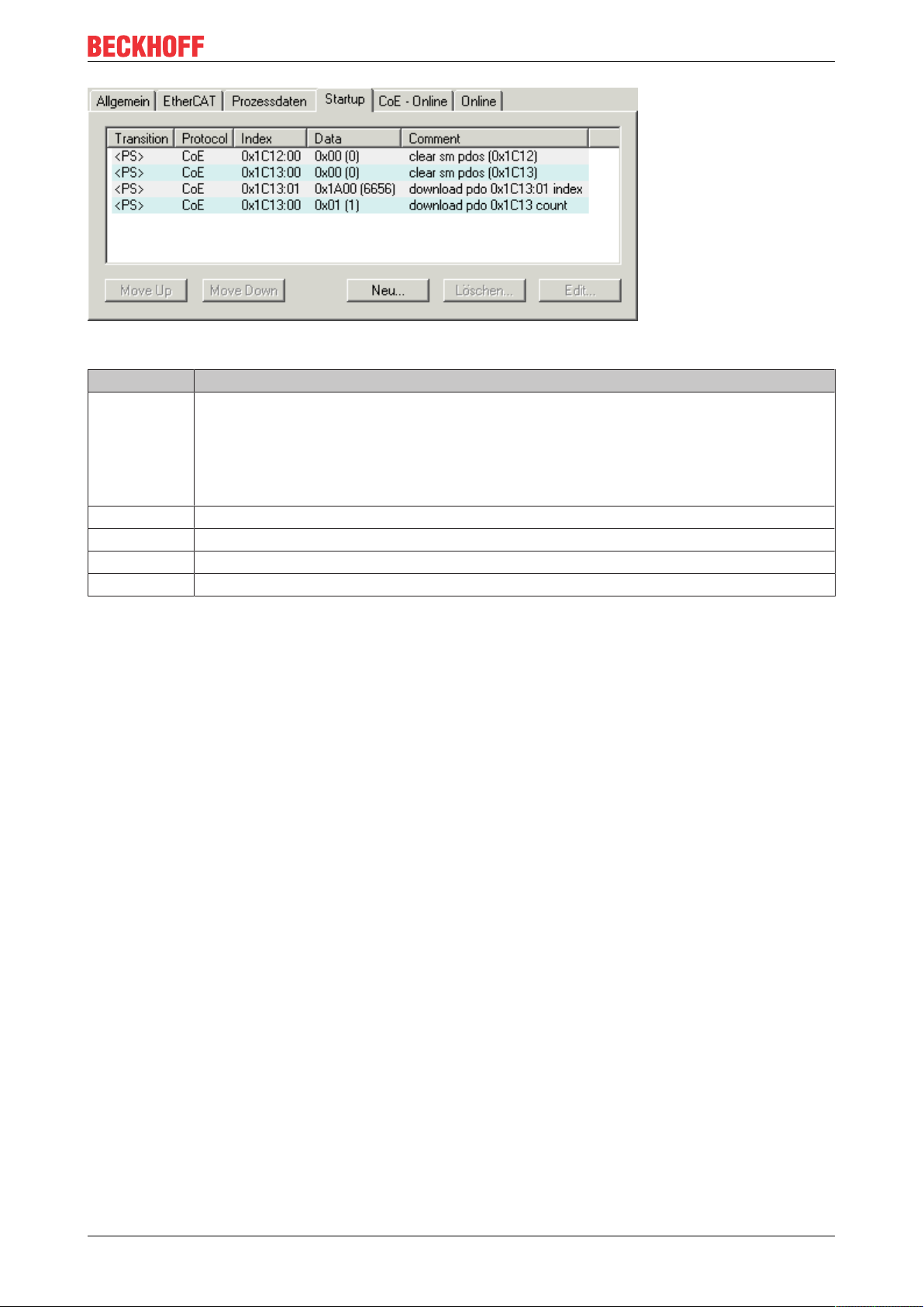
Fig.79: „Startup“ tab
Column Description
Transition Transition to which the request is sent. This can either be
• the transition from pre-operational to safe-operational (PS), or
• the transition from safe-operational to operational (SO).
If the transition is enclosed in "<>" (e.g. <PS>), the mailbox request is fixed and cannot be
modified or deleted by the user.
Protocol Type of mailbox protocol
Index Index of the object
Data Date on which this object is to be downloaded.
Comment Description of the request to be sent to the mailbox
Commissioning
Move Up This button moves the selected request up by one
position in the list.
Move Down This button moves the selected request down by one
position in the list.
New This button adds a new mailbox download request to
be sent during startup.
Delete This button deletes the selected entry.
Edit This button edits an existing request.
“CoE – Online” tab
The additional CoE - Online tab is displayed if the EtherCAT slave supports the CANopen over EtherCAT
(CoE) protocol. This dialog lists the content of the object list of the slave (SDO upload) and enables the user
to modify the content of an object from this list. Details for the objects of the individual EtherCAT devices can
be found in the device-specific object descriptions.
EL5042 69Version: 1.5
Page 70

Commissioning
Fig.80: “CoE – Online” tab
Object list display
Column Description
Index Index and sub-index of the object
Name Name of the object
Flags RW The object can be read, and data can be written to the object (read/write)
RO The object can be read, but no data can be written to the object (read only)
P An additional P identifies the object as a process data object.
Value Value of the object
Update List The Update list button updates all objects in the displayed list
Auto Update If this check box is selected, the content of the objects is updated automatically.
Advanced The Advanced button opens the Advanced Settings dialog. Here you can specify
which objects are displayed in the list.
EL504270 Version: 1.5
Page 71
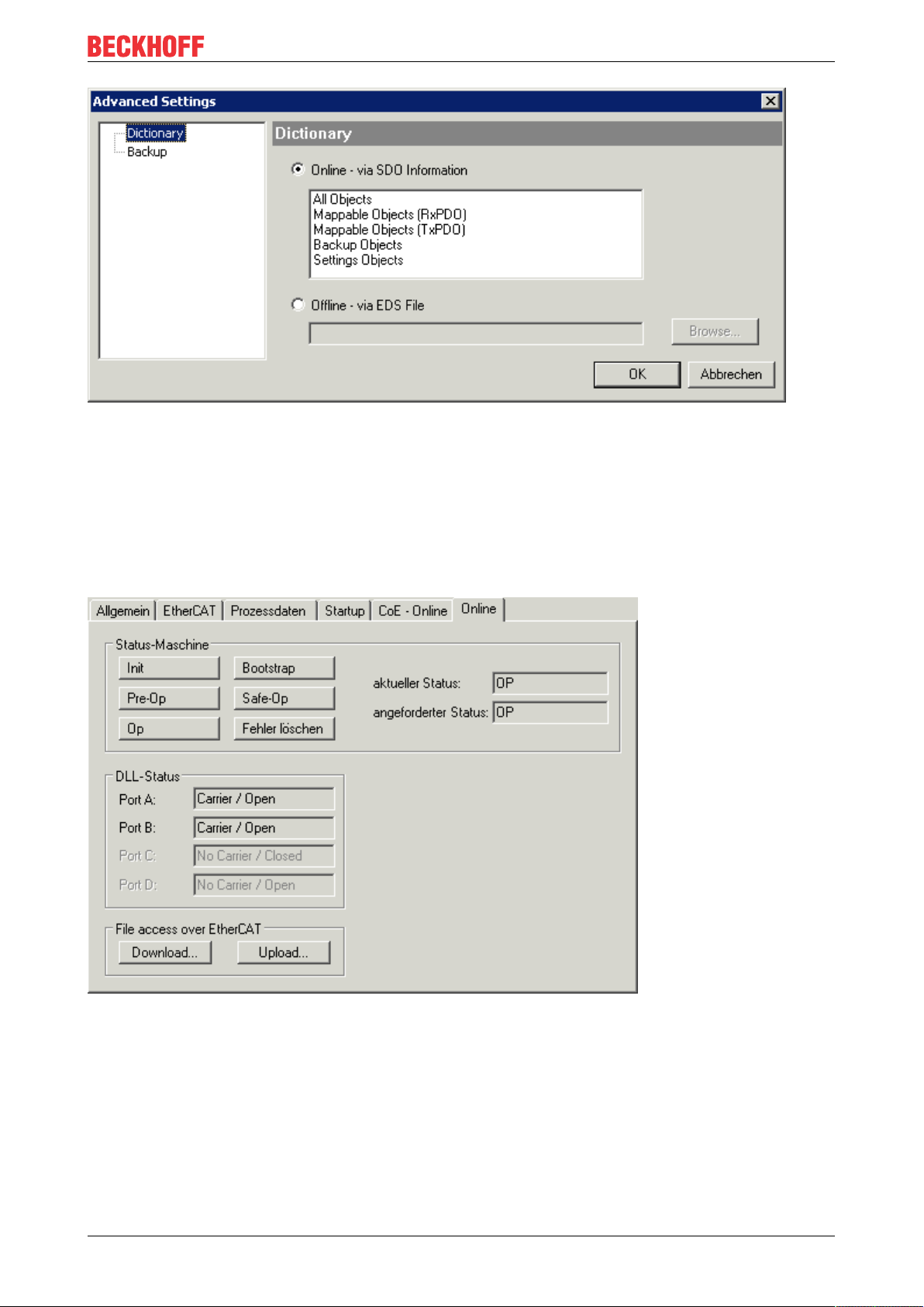
Commissioning
Fig.81: Dialog “Advanced settings”
Online - via SDO Information If this option button is selected, the list of the objects included in the object
list of the slave is uploaded from the slave via SDO information. The list
below can be used to specify which object types are to be uploaded.
Offline - via EDS File If this option button is selected, the list of the objects included in the object
list is read from an EDS file provided by the user.
„Online“ tab
Fig.82: „Online“ tab
EL5042 71Version: 1.5
Page 72

Commissioning
State Machine
Init This button attempts to set the EtherCAT device to the Init state.
Pre-Op This button attempts to set the EtherCAT device to the pre-operational state.
Op This button attempts to set the EtherCAT device to the operational state.
Bootstrap This button attempts to set the EtherCAT device to the Bootstrap state.
Safe-Op This button attempts to set the EtherCAT device to the safe-operational state.
Clear Error This button attempts to delete the fault display. If an EtherCAT slave fails during
change of state it sets an error flag.
Example: An EtherCAT slave is in PREOP state (pre-operational). The master now
requests the SAFEOP state (safe-operational). If the slave fails during change of state
it sets the error flag. The current state is now displayed as ERR PREOP. When the
Clear Error button is pressed the error flag is cleared, and the current state is
displayed as PREOP again.
Current State Indicates the current state of the EtherCAT device.
Requested State Indicates the state requested for the EtherCAT device.
DLL Status
Indicates the DLL status (data link layer status) of the individual ports of the EtherCAT slave. The DLL status
can have four different states:
Status Description
No Carrier / Open No carrier signal is available at the port, but the port is open.
No Carrier / Closed No carrier signal is available at the port, and the port is closed.
Carrier / Open A carrier signal is available at the port, and the port is open.
Carrier / Closed A carrier signal is available at the port, but the port is closed.
File Access over EtherCAT
Download With this button a file can be written to the EtherCAT device.
Upload With this button a file can be read from the EtherCAT device.
"DC" tab (Distributed Clocks)
Fig.83: "DC" tab (Distributed Clocks)
Operation Mode Options (optional):
• FreeRun
• SM-Synchron
• DC-Synchron (Input based)
• DC-Synchron
Advanced Settings… Advanced settings for readjustment of the real time determinant TwinCAT-
clock
Detailed information to Distributed Clocks are specified on http://infosys.beckhoff.com:
EL504272 Version: 1.5
Page 73

Commissioning
Fieldbus Components → EtherCAT Terminals → EtherCAT System documentation → EtherCAT basics →
Distributed Clocks
5.2.7.1 Detailed description of Process Data tab
Sync Manager
Lists the configuration of the Sync Manager (SM).
If the EtherCAT device has a mailbox, SM0 is used for the mailbox output (MbxOut) and SM1 for the mailbox
input (MbxIn).
SM2 is used for the output process data (outputs) and SM3 (inputs) for the input process data.
If an input is selected, the corresponding PDO assignment is displayed in the PDO Assignment list below.
PDO Assignment
PDO assignment of the selected Sync Manager. All PDOs defined for this Sync Manager type are listed
here:
• If the output Sync Manager (outputs) is selected in the Sync Manager list, all RxPDOs are displayed.
• If the input Sync Manager (inputs) is selected in the Sync Manager list, all TxPDOs are displayed.
The selected entries are the PDOs involved in the process data transfer. In the tree diagram of the System
Manager these PDOs are displayed as variables of the EtherCAT device. The name of the variable is
identical to the Name parameter of the PDO, as displayed in the PDO list. If an entry in the PDO assignment
list is deactivated (not selected and greyed out), this indicates that the input is excluded from the PDO
assignment. In order to be able to select a greyed out PDO, the currently selected PDO has to be deselected
first.
Activation of PDO assignment
ü If you have changed the PDO assignment, in order to activate the new PDO assignment,
a) the EtherCAT slave has to run through the PS status transition cycle (from pre-operational to
safe-operational) once (see Online tab [}71]),
b) and the System Manager has to reload the EtherCAT slaves
( button for TwinCAT2 or button for TwinCAT3)
PDO list
List of all PDOs supported by this EtherCAT device. The content of the selected PDOs is displayed in the
PDO Content list. The PDO configuration can be modified by double-clicking on an entry.
Column Description
Index PDO index.
Size Size of the PDO in bytes.
Name Name of the PDO.
If this PDO is assigned to a Sync Manager, it appears as a variable of the slave with this
parameter as the name.
Flags F Fixed content: The content of this PDO is fixed and cannot be changed by the
System Manager.
M Mandatory PDO. This PDO is mandatory and must therefore be assigned to a
Sync Manager! Consequently, this PDO cannot be deleted from the PDO
Assignment list
SM Sync Manager to which this PDO is assigned. If this entry is empty, this PDO does not take
part in the process data traffic.
SU Sync unit to which this PDO is assigned.
EL5042 73Version: 1.5
Page 74

Commissioning
PDO Content
Indicates the content of the PDO. If flag F (fixed content) of the PDO is not set the content can be modified.
Download
If the device is intelligent and has a mailbox, the configuration of the PDO and the PDO assignments can be
downloaded to the device. This is an optional feature that is not supported by all EtherCAT slaves.
PDO Assignment
If this check box is selected, the PDO assignment that is configured in the PDO Assignment list is
downloaded to the device on startup. The required commands to be sent to the device can be viewed in the
Startup [}68] tab.
PDO Configuration
If this check box is selected, the configuration of the respective PDOs (as shown in the PDO list and the
PDO Content display) is downloaded to the EtherCAT slave.
5.3 General Notes - EtherCAT Slave Application
This summary briefly deals with a number of aspects of EtherCAT Slave operation under TwinCAT. More
detailed information on this may be found in the corresponding sections of, for instance, the EtherCAT
System Documentation.
Diagnosis in real time: WorkingCounter, EtherCAT State and Status
Generally speaking an EtherCAT Slave provides a variety of diagnostic information that can be used by the
controlling task.
This diagnostic information relates to differing levels of communication. It therefore has a variety of sources,
and is also updated at various times.
Any application that relies on I/O data from a fieldbus being correct and up to date must make diagnostic
access to the corresponding underlying layers. EtherCAT and the TwinCAT System Manager offer
comprehensive diagnostic elements of this kind. Those diagnostic elements that are helpful to the controlling
task for diagnosis that is accurate for the current cycle when in operation (not during commissioning) are
discussed below.
EL504274 Version: 1.5
Page 75

Fig.84: Selection of the diagnostic information of an EtherCAT Slave
Commissioning
In general, an EtherCAT Slave offers
• communication diagnosis typical for a slave (diagnosis of successful participation in the exchange of
process data, and correct operating mode)
This diagnosis is the same for all slaves.
as well as
• function diagnosis typical for a channel (device-dependent)
See the corresponding device documentation
The colors in Fig. “Selection of the diagnostic information of an EtherCAT Slave” also correspond to the
variable colors in the System Manager, see Fig. “Basic EtherCAT Slave Diagnosis in the PLC”.
Colour Meaning
yellow Input variables from the Slave to the EtherCAT Master, updated in every cycle
red Output variables from the Slave to the EtherCAT Master, updated in every cycle
green Information variables for the EtherCAT Master that are updated acyclically. This means that
it is possible that in any particular cycle they do not represent the latest possible status. It is
therefore useful to read such variables through ADS.
Fig. “Basic EtherCAT Slave Diagnosis in the PLC” shows an example of an implementation of basic
EtherCAT Slave Diagnosis. A Beckhoff EL3102 (2-channel analogue input terminal) is used here, as it offers
both the communication diagnosis typical of a slave and the functional diagnosis that is specific to a channel.
Structures are created as input variables in the PLC, each corresponding to the process image.
EL5042 75Version: 1.5
Page 76
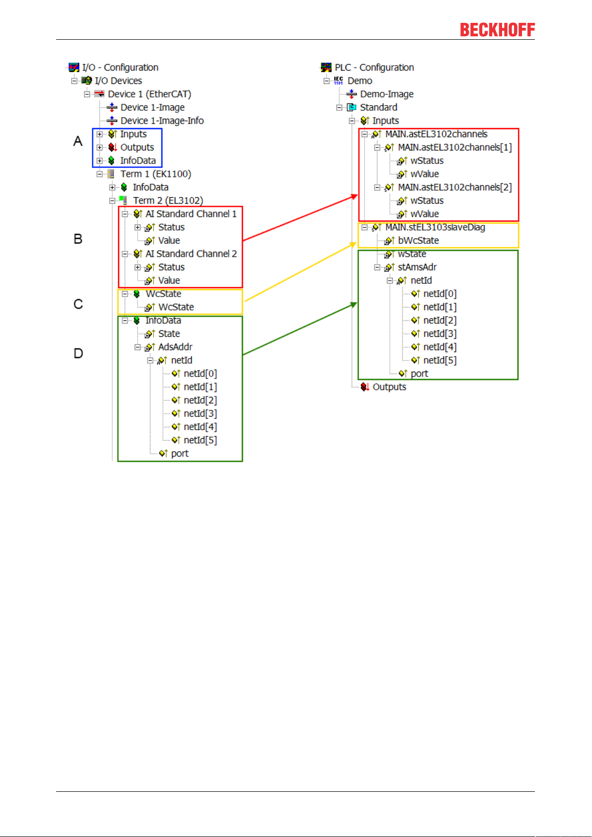
Commissioning
Fig.85: Basic EtherCAT Slave Diagnosis in the PLC
The following aspects are covered here:
EL504276 Version: 1.5
Page 77

Code Function Implementation Application/evaluation
A The EtherCAT Master's diagnostic infor-
mation
updated acyclically (yellow) or provided
acyclically (green).
B In the example chosen (EL3102) the
EL3102 comprises two analogue input
channels that transmit a single function
status for the most recent cycle.
C For every EtherCAT Slave that has cyclic
process data, the Master displays, using
what is known as a WorkingCounter,
whether the slave is participating successfully and without error in the cyclic exchange of process data. This important, elementary information is therefore provided
for the most recent cycle in the System
Manager
1. at the EtherCAT Slave, and, with
identical contents
2. as a collective variable at the
EtherCAT Master (see Point A)
for linking.
D Diagnostic information of the EtherCAT
Master which, while it is represented at the
slave for linking, is actually determined by
the Master for the Slave concerned and
represented there. This information cannot
be characterized as real-time, because it
• is only rarely/never changed,
except when the system starts up
• is itself determined acyclically (e.g.
EtherCAT Status)
Status
• the bit significations may be
found in the device
documentation
• other devices may supply
more information, or none
that is typical of a slave
WcState (Working Counter)
0: valid real-time communication in
the last cycle
1: invalid real-time communication
This may possibly have effects on
the process data of other Slaves
that are located in the same SyncUnit
State
current Status (INIT..OP) of the
Slave. The Slave must be in OP
(=8) when operating normally.
AdsAddr
The ADS address is useful for
communicating from the PLC/task
via ADS with the EtherCAT Slave,
e.g. for reading/writing to the CoE.
The AMS-NetID of a slave corresponds to the AMS-NetID of the
EtherCAT Master; communication
with the individual Slave is possible
via the port (= EtherCAT address).
At least the DevState is to be evaluated for
the most recent cycle in the PLC.
The EtherCAT Master's diagnostic information offers many more possibilities than are
treated in the EtherCAT System Documentation. A few keywords:
• CoE in the Master for communication
with/through the Slaves
• Functions from TcEtherCAT.lib
• Perform an OnlineScan
In order for the higher-level PLC task (or corresponding control applications) to be able to
rely on correct data, the function status must
be evaluated there. Such information is
therefore provided with the process data for
the most recent cycle.
In order for the higher-level PLC task (or corresponding control applications) to be able to
rely on correct data, the communication status of the EtherCAT Slave must be evaluated
there. Such information is therefore provided
with the process data for the most recent cycle.
Information variables for the EtherCAT Master that are updated acyclically. This means
that it is possible that in any particular cycle
they do not represent the latest possible status. It is therefore possible to read such variables through ADS.
Commissioning
NOTE
Diagnostic information
It is strongly recommended that the diagnostic information made available is evaluated so that the application can react accordingly.
CoE Parameter Directory
The CoE parameter directory (CanOpen-over-EtherCAT) is used to manage the set values for the slave
concerned. Changes may, in some circumstances, have to be made here when commissioning a relatively
complex EtherCAT Slave. It can be accessed through the TwinCAT System Manager, see Fig. “EL3102,
CoE directory”:
EL5042 77Version: 1.5
Page 78

Commissioning
Fig.86: EL3102, CoE directory
EtherCAT System Documentation
The comprehensive description in the EtherCAT System Documentation (EtherCAT Basics --> CoE
Interface) must be observed!
A few brief extracts:
• Whether changes in the online directory are saved locally in the slave depends on the device. EL
terminals (except the EL66xx) are able to save in this way.
• The user must manage the changes to the StartUp list.
Commissioning aid in the TwinCAT System Manager
Commissioning interfaces are being introduced as part of an ongoing process for EL/EP EtherCAT devices.
These are available in TwinCAT System Managers from TwinCAT 2.11R2 and above. They are integrated
into the System Manager through appropriately extended ESI configuration files.
EL504278 Version: 1.5
Page 79

Commissioning
Fig.87: Example of commissioning aid for a EL3204
This commissioning process simultaneously manages
• CoE Parameter Directory
• DC/FreeRun mode
• the available process data records (PDO)
Although the "Process Data", "DC", "Startup" and "CoE-Online" that used to be necessary for this are still
displayed, it is recommended that, if the commissioning aid is used, the automatically generated settings are
not changed by it.
The commissioning tool does not cover every possible application of an EL/EP device. If the available setting
options are not adequate, the user can make the DC, PDO and CoE settings manually, as in the past.
EtherCAT State: automatic default behaviour of the TwinCAT System Manager and manual operation
After the operating power is switched on, an EtherCAT Slave must go through the following statuses
• INIT
• PREOP
• SAFEOP
• OP
to ensure sound operation. The EtherCAT Master directs these statuses in accordance with the initialization
routines that are defined for commissioning the device by the ES/XML and user settings (Distributed Clocks
(DC), PDO, CoE). See also the section on "Principles of Communication, EtherCAT State Machine [}19]" in
this connection. Depending how much configuration has to be done, and on the overall communication,
booting can take up to a few seconds.
The EtherCAT Master itself must go through these routines when starting, until it has reached at least the
OP target state.
The target state wanted by the user, and which is brought about automatically at start-up by TwinCAT, can
be set in the System Manager. As soon as TwinCAT reaches the status RUN, the TwinCAT EtherCAT
Master will approach the target states.
EL5042 79Version: 1.5
Page 80
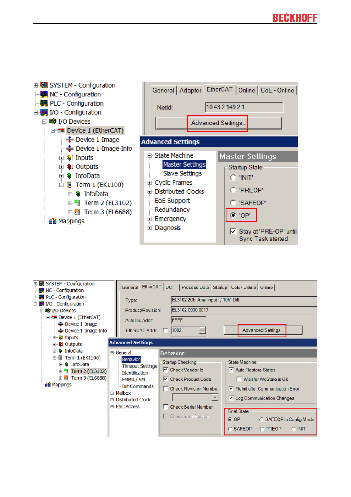
Commissioning
Standard setting
The advanced settings of the EtherCAT Master are set as standard:
• EtherCAT Master: OP
• Slaves: OP
This setting applies equally to all Slaves.
Fig.88: Default behaviour of the System Manager
In addition, the target state of any particular Slave can be set in the "Advanced Settings" dialogue; the
standard setting is again OP.
Fig.89: Default target state in the Slave
EL504280 Version: 1.5
Page 81

Commissioning
Manual Control
There are particular reasons why it may be appropriate to control the states from the application/task/PLC.
For instance:
• for diagnostic reasons
• to induce a controlled restart of axes
• because a change in the times involved in starting is desirable
In that case it is appropriate in the PLC application to use the PLC function blocks from the TcEtherCAT.lib,
which is available as standard, and to work through the states in a controlled manner using, for instance,
FB_EcSetMasterState.
It is then useful to put the settings in the EtherCAT Master to INIT for master and slave.
Fig.90: PLC function blocks
Note regarding E-Bus current
EL/ES terminals are placed on the DIN rail at a coupler on the terminal strand. A Bus Coupler can supply the
EL terminals added to it with the E-bus system voltage of 5 V; a coupler is thereby loadable up to 2 A as a
rule. Information on how much current each EL terminal requires from the E-bus supply is available online
and in the catalogue. If the added terminals require more current than the coupler can supply, then power
feed terminals (e.g. EL9410) must be inserted at appropriate places in the terminal strand.
The pre-calculated theoretical maximum E-Bus current is displayed in the TwinCAT System Manager as a
column value. A shortfall is marked by a negative total amount and an exclamation mark; a power feed
terminal is to be placed before such a position.
EL5042 81Version: 1.5
Page 82

Commissioning
Fig.91: Illegally exceeding the E-Bus current
From TwinCAT 2.11 and above, a warning message "E-Bus Power of Terminal..." is output in the logger
window when such a configuration is activated:
Fig.92: Warning message for exceeding E-Bus current
NOTE
Caution! Malfunction possible!
The same ground potential must be used for the E-Bus supply of all EtherCAT terminals in a terminal block!
EL504282 Version: 1.5
Page 83

Commissioning
5.4 Process data & parameter setting
5.4.1 Sync Manager (SM)
The extent of the process data that is made available can be changed via the “Process data” tab (see Fig.
Process data tab SM3, EL5042 (default)).
Fig.93: Process data tab SM3, EL5032.(default)
5.4.2 PDO Assignment
To configure the process data, select the required Sync Manager (SM 2 or SM 3) in the "Sync Manager" field
at the top left.The process data assigned to this Sync Manager can then be switched on or off in the “PDO
Assignment” box underneath. Restarting the EtherCAT system, or reloading the configuration in
configuration mode (F4), causes the EtherCAT communication to restart, and the process data is transferred
from the terminal.
The following PDO Assignments are available:
EL5042 83Version: 1.5
Page 84

Commissioning
SM3, PDO-Zuordnung 0x1C13
Index Size (byte.bit) Name PDO content Size (byte.bit)
0x1A00 (default)
FB Inputs Channel 1
0x1A01 (default)
FB Inputs Channel 2
0x1A02
FB Inputs Channel 1
compact
0x1A03
FB Inputs Channel 2
compact
10.0 Status_Warning
Status_Error
Status_Ready
[Offset] - 0.5
[Offset] - 0.4
Status_Diag
Status_TxPDO State
Status_Input Cycle counter
Position
10.0 Status_Warning
Status_Error
Status_Ready
[Offset] - 0.5
[Offset] - 0.4
Status_Diag
Status_TxPDO State
Status_Input Cycle counter
Position
6.0 Status_Warning
Status_Error
Status_Ready
[Offset] - 0.5
[Offset] - 0.4
Status_Diag
Status_TxPDO State
Status_Input Cycle counter
Position
6.0 Status_Warning
Status_Error
Status_Ready
[Offset] - 0.5
[Offset] - 0.4
Status_Diag
Status_TxPDO State
Status_Input Cycle counter
Position
Index 0x6000:01 [}91]
Index 0x6000:02 [}91]
Index 0x6000:03 [}91]
Index 0x6000:0D [}91]
Index 0x6000:0E [}91]
Index 0x6000:0F [}91]
Index 0x6000:11 [}91]
Index 0x6010:01 [}91]
Index 0x6010:02 [}91]
Index 0x6010:03 [}91]
Index 0x6010:0D [}91]
Index 0x6010:0E [}91]
Index 0x6010:0F [}91]
Index 0x6010:11 [}91]
0.1
0.1
0.1
0.1
0.1
0.2
8.0
0.1
0.1
0.1
0.1
0.1
0.2
8.0
0.1
0.1
0.1
0.1
0.1
0.2
4.0
0.1
0.1
0.1
0.1
0.1
0.2
4.0
EL504284 Version: 1.5
Page 85

Commissioning
5.4.3 Predefined PDO Assignment
The "Predefined PDO Assignment" enables a simplified selection of the process data. The desired function is
selected on the lower part of the "Process Data" tab. As a result, all necessary PDOs are automatically
activated and the unnecessary PDOs are deactivated.
4 PDO assignments are available:
Name SM3, PDO assignment
1 Ch. Standard
1 Ch. Compact
2 Ch. Standard
2 Ch. Compact
0x1A00 [}94] (FB Inputs Channel 1)
0x1A02 [}94] (FB Inputs Channel 1 compact)
0x1A00 [}94] (FB Inputs Channel 2)
0x1A02 [}94] (FB Inputs Channel 2 compact)
Fig.94: Process data tab Predefined PDO Assignment, EL5042
5.4.4 Overview of commands and samples
The EL5042 provides 5V and 9V encoder power supply (0x80p8:12 supply voltage) for both channels with
max. 0.5 A.
Setting the encoder supply voltage
To write 0x8008:12 [}90] “Supply Voltage”, the value 0x72657375 (ASCII: “user”) must be set in
0xF008 “Code word”. Specification in steps of 0.1 V.
Only the values 50 (5.0 V) and 90 (9.0 V) are permissible. This setting applies to both channels;
therefore, before switching to 9.0 V, it must be ensured that both BiSS encoders support the extended voltage range! The setting is only adopted in the “INIT” state.
The encoder supply voltage is set for both channels in object 0x8008:12 [}90]!
The terminal works as a BiSS-C and also as SSI master. Various parameters have to be set to ensure, that
the data of the slave are transmitted correctly.
Parametrization of EL5042 as BiSS-C master
• BiSS-C mode (0x80p8:18)
◦ in the Object 0x80p8:18 Mode: BiSS-C (0x00) need to be selected
• CRC polynomial (0x80p8:11)
◦ The transmission of the data is CRC-secured. The counter polynomial for CRC determination is
slave specific. Is the CRC transmitted inverted, the 0x80p8:13 need to be set to TRUE.
• Clock frequency (0x80p8:13)
◦ Clock rate, limitations by the max. cable length need to be considered. A runtime compensation for
the clock and data line is implemented, therefore the use of long cables and high data rates is
possible (max. 10MHz).
• Multiturn [Bit] (0x80p8:15)
◦ Number of multiturn bits provided by the slave. If only singleturn bits are provided (e.g. linear
encoder) the value can be set to 0.
• Singleturn [Bit] (0x80p8:16)
◦ Number of singleturn bits provided by the slave.
EL5042 85Version: 1.5
Page 86

Commissioning
• Offset LSB Bit [Bit] (0x80p8:17)
◦ Right aligned offset bits (null bits) can be set, if available (slave specific). The position data is
shifted by the number of the offset bits.
Note about the counter polynomial
The counter polynomial for the CRC determination is manufacturer-specific.
Common values are 0x43
This value can be entered directly in the object 0x80p8:11 [}90].
The calculation of the polynomial and the cyclical data check between master and slave are carried
out automatically.
The BiSS-C frame structure is following:
hex
(67
) or 0x97
dec
hex
(151
dec
).
Offset MSB Bit
(optional)
Not relevant Multiturn
Position
[max. 64 Bit]
data
0x80p8:15
Multiturn
Singleturn
data
0x80p8:16
Singleturn
Parametrization of EL5042 as SSI master
• SSI mode (0x80p8:18)
◦ in the Object 0x80p8:18 Mode: SSI (0x01) need to be selected
◦ CRC polynomial (0x80p8:11) is automatically set to 0
◦ Status Bits are automatically disabled (0x80p8:02 set to TRUE)
• Clock frequency (0x80p8:13)
◦ Clock rate, limitations by the max. cable length need to be considered. Max. Frequency for SSI
2MHz, slave specific
• Multiturn [Bit] (0x80p8:15)
◦ Number of multiturn bits provided by the slave. If only singleturn bits are provided (e.g. linear
encoder) the value can be set to 0.
• Singleturn [Bit] (0x80p8:16)
◦ Number of singleturn bits provided by the slave.
• Offset LSB Bit [Bit] (0x80p8:17)
◦ Right aligned offset bits (additional bits, which should be blend out of the SSI frame) can be set, if
available (slave specific). The position data is shifted by the number of the offset bits.
Offset LSB Bit
(optional)
Error
[1Bit]
Warning [1Bit] CRC
[8Bit]
Optional Status Bits CRC
polynomial
0x80p8:17
Offset LSB Bit
(right aligned)
0x80p8:02 Disable Status Bits =
TRUE; bits will not be analyzed
separately
0x80p8:11
CRC
Polynomial
The SSI frame structure is following:
Position
[max. 64 Bit]
Offset LSB Bit
(optional)
Error
[1Bit] (op-
Warning [1Bit]
(optional)
tional)
Multiturn data Singleturn data Optional Status Bits, disabled per default
0x80p8:15 Multiturn 0x80p8:16 Singleturn 0x80p8:17
Offset LSB Bit
(right aligned)
0x80p8:02 Disable Status Bits
= TRUE (default for SSI mode);
bits will not be analyzed
separately
Are additional bits in the SSI frame available (e.g. parity bit or power good bit), and should these bits be
blended out, offset bits (0x80p8:17) can be set. The position data is than shifted by the number of the offset
bits.
EL504286 Version: 1.5
Page 87

Description of Object 0x80p8: FB BiSS Settings
Index Name Meaning Default
0x80p8:01 Invert feedback direction FALSE: 64-bit position value
FALSE
TRUE: Negates the 64-bit position
value
0x80p8:02 Disable Status Bits FALSE: status bits enabled
FALSE
TRUE: status bits disabled
0x80p8:03 CRC Invert FALSE: CRC invert deactivated
TRUE
TRUE: CRC is transferred invert
0x80p8:11 CRC Polynomial Counter polynomial for CRC
0x00000043 (67
determination
0: Transmission is not CRC-secured
(slave specific)
0x80p8:12 Supply Voltage Encoder supply voltage:
5.0V (50)
50: 5.0 V
90: 9.0 V (see note below)
0x80p8:13 Clock Frequency 0: 10 MHz
0x00 (0
1: 5 MHZ
2: 3.33 MHz
3: 2.5 MHz
4: 2 MHz
9: 1 MHz
17: 500 kHz
19: 250 kHz
0x80p8:14 Coding 0: Dual code active
0x00 (0
1: Gray code active
0x80p8:15 Multiturn [Bit] Number of multiturn bits 0x0C (12
0x80p8:16 Singleturn [Bit] Number of singleturn bits 0x0D (13
0x80p8:17 Offset LSB Bit [Bit] Number of right aligned offset bits 0x00 (0
0x80p8:18 Mode 0: BiSS-C mode
0x00 (0
1: SSI mode
Commissioning
dec
)
dec
)
dec
)
dec
)
dec
)
dec
)
dec
)
NOTE
Possible damage of devices!
If the object 0x80p8:11 CRC polynomial is set to “0”, the data transmission is not CRC secured anymore.
Therefore wrong counter values may not be detected by the terminal!
Process data
Following process data are provided:
EL5042 87Version: 1.5
Page 88

Commissioning
Fig.95: EL5042, process data
The interpretation of the process data depend on the mode (BiSS-C or SSI).
Name Description for BiSS-C mode
Status_Warning Status bit “Warning” is part of the BiSS-C frame and is directly communicated from the
slave. The bit is active high. For troubleshooting please refer to slave documentation.
Status_Error Status bit “Error” is part of the BiSS-C frame and is directly communicated from the
slave. The bit is active high. If the error bit is high, it will be also displayed in the
“TxPDO State”. For troubleshooting please refer to slave documentation.
Status_Ready In the idle state of BiSS-C communication the slave indicates his ready state with high
value. Only if the ready bit is high, data transmission can be started.
If the ready bit is low, please check chapter error handling
Status_Diag Indicates that a new message is available in the “Diag History”
Status_TxPDO State Validity of the data of the associated TxPDO
0 = valid
1 = invalid
Status_Input cycle
counter
Position BiSS-C position value
2-bit counter for synchronization, is incremented only if a
new value is present
EL504288 Version: 1.5
Page 89

Commissioning
Name Description for SSI mode
Status_Warning Status bit “Warning” is deactivated by default in SSI mode.
If status bits are activated (0x80p8:02 Disable Status Bits = FALSE), the last 2 bits of
the SSI frame are directly mapped as warning and error bit.
Status_Error Status bit “Error” is deactivated by default in SSI mode.
If status bits are activated (0x80p8:02 Disable Status Bits = FALSE), the last 2 bits of
the SSI frame are directly mapped as warning and error bit.
Status_Ready In the idle state of SSI communication the slave indicates his ready state with high
value. Only if the ready bit is high, data transmission can be started.
If the ready bit is low, please check chapter error handling
Status_Diag Indicates that a new message is available in the “Diag History”
Status_TxPDO State Validity of the data of the associated TxPDO
0 = valid
1 = invalid
Status_Input cycle
counter
Position SSI position value
2-bit counter for synchronization, is incremented only if a
new value is present
Cycle time
The minimum cycle time of the EL5042 depends on the configuration of the terminal.
At least with the predefined PDO assignment “1 Ch. Standard” and the default settings (BiSS-C mode, 10
MHz clock frequency), a cycle time of 100 µs can be realized.
If another configuration, than the predefined PDO assignment “1 Ch. Standard”, is used, the minimum cycle
time can be read out in the object 0x1C33:05 minimum cycle time, by set the object 0x1C33:08 command to
1.
5.5 Object description and parameterization
EtherCAT XML Device Description
The display matches that of the CoE objects from the EtherCAT XML Device Description. We recommend downloading the latest XML file from the download area of the Beckhoff website and in-
stalling it according to installation instructions.
Parameterization via the CoE list (CAN over EtherCAT)
The EtherCAT device is parameterized via the CoE-Online tab [}69] (double-click on the respective
object) or via the Process Data tab [}66](allocation of PDOs). Please note the following general CoE
notes [}21] when using/manipulating the CoE parameters:
• Keep a startup list if components have to be replaced
• Differentiation between online/offline dictionary, existence of current XML description
• use “CoE reload” for resetting changes
EL5042 89Version: 1.5
Page 90

Commissioning
5.5.1 Restore object
Index 1011 Restore default parameters
Index
Name Meaning Data type Flags Default
(hex)
1011:0
Restore default parame-
Restore default parameters UINT8 RO 0x01 (1
)
dec
ters [}120]
1011:01 SubIndex 001 If this object is set to "0x64616F6C" in the set value dia-
UINT32 RW 0x00000000 (0
log, all backup objects are reset to their delivery state.
5.5.2 Configuration data
Index 80p0 FB Settings (for Ch.1, p = 0; Ch.2, p = 1)
Index (hex) Name Meaning Data type Flags Default
80p0:0 FB Settings Max. subindex UINT8 RO > 17 <
80p0:01 Invert feedback direc-
tion
80p0:11 Device type 03: BiSS UINT32 RW 0x00000003
Index 80p8 FB BiSS-C settings (for Ch.1, p = 0; Ch.2, p = 1)
Index (hex) Name Meaning Data type Flags Default
80p8:0 FB BiSS-C settings Max. subindex UINT8 RO > 24 <
80p8:01 Invert feedback direc-
tion
0x80p8:02 Disable Status Bits FALSE: status bits enabled
0x80p8:03 CRC Invert FALSE: CRC invert deactivated
0x80p8:11 CRC Polynomial Counter polynomial for CRC determination
0x80p8:12 Supply Voltage Encoder supply voltage:
0x80p8:13 Clock Frequency 0: 10 MHz
0x80p8:14 Coding 0: Dual code active
0x80p8:15 Multiturn [Bit] Number of multiturn bits UINT8 RW 0x0C (12
0x80p8:16 Singleturn [Bit] Number of singleturn bits UINT8 RW 0x0D (13
0x80p8:17 Offset LSB Bit [Bit] Number of “right aligned” Offset bits UINT8 RW 0x00 (0
0x80p8:18 Mode 0: BiSS-C mode
TRUE: Negates the 64-bit position value BOOLEAN RW FALSE
(2
)
dec
FALSE: 64-bit position value
BOOLEAN RW FALSE
TRUE: Negates the 64-bit position value
BOOLEAN RW FALSE
TRUE: status bits disabled
BOOLEAN RW TRUE
TRUE: CRC is transferred invert
INT64 RW 0x00000043
(67
0: Transmission is not CRC-secured (slave specific)
dec
UINT8 RW 5.0V (50)
50: 5.0 V
90: 9.0 V (see note below)
UINT8 RW 0x00 (0
1: 5 MHZ
2: 3.33 MHz
3: 2.5 MHz
4: 2 MHz
9: 1 MHz
17: 500 kHz
19: 250 kHz
UINT8 RW 0x00 (0
1: Gray code active
UINT8 RW 0x00 (0
1: SSI mode
)
dec
dec
dec
dec
dec
dec
)
dec
)
)
)
)
)
)
EL504290 Version: 1.5
Page 91

Commissioning
Setting the encoder supply voltage
To write 0x8008:12 [}90] “Supply Voltage”, the value 0x72657375 (ASCII: “user”) must be set in
0xF008 [}97] “Code word”. Specification in steps of 0.1 V.
Only the values 50 (5.0 V) and 90 (9.0 V) are permissible. This setting applies to both channels;
therefore, before switching to 9.0 V, it must be ensured that both BiSS encoders support the extended voltage range! The setting is only adopted in the “INIT” state.
The encoder supply voltage is set for both channels in object 0x8008:12 [}90]!
5.5.3 Command object
Index B0p8 FB BiSS-C Command (for Ch.1, p = 0; Ch.2, p = 1)
Index (hex) Name Meaning Data type Flags Default
B0p8:0 FB BiSS-C Command Max. subindex UINT8 RO > 3 <
B0p8:01 Request
B0p8:02 Status Status of the command currently being executed
B0p8:03 Response Optional response value of the command
The Object command [}85] can be used to initiate various actions, such as the reading or writing of a particular
memory range of the BiSS-C encoder.
Request: up to 69 bytes
0: Command executed without error and without response
1: Command executed without error and with response
2: Command executed with error and without response
3: Command executed with error and with response
255: Command is being executed
Response: up to 69 bytes
OCTETSTRING[69]
UINT8 RO 0x00 (0
OCTETSTRING[69]
RW
RO
)
dec
5.5.4 Input data
Index 60p0 FB Inputs (for Ch.1, p = 0; Ch.2, p = 1)
Index (hex) Name Meaning Data type Flags Default
60p0:0 FB Inputs Max. subindex UINT8 RO > 17 <
60p0:01 STATUS_Warning Warning bit of the BiSS-C protocol BOOLEAN RO FALSE
60p0:02 STATUS_Error Error collecting bit of the BiSS-C protocol (error message
60p0:03 STATUS_Ready Ready for use (initialization of the encoder completed) BOOLEAN RO FALSE
60p0:0D STATUS_Diag Indicates that a new message is available in the “Diag
60p0:0E STATUS_TxPDO
State
60p0:0F STATUS_Input cycle
counter
60p0:11 Position BiSS-C position value UINT64 RO 00 00 00 00
1/ error message 2)
History”
Validity of the data of the associated TxPDO (0 = valid, 1
= invalid)
2-bit counter for synchronization (incremented only if a
new value is present)
BOOLEAN RO FALSE
BOOLEAN RO TRUE
BOOLEAN RO TRUE
BIT2 RO 0
00 00 00 00
EL5042 91Version: 1.5
Page 92

Commissioning
5.5.5 Diagnostic data
Index 10F3 Diagnosis History
Index (hex) Name Meaning Data type Flags Default
10F3:0 Diagnosis History Maximum subindex UINT8 RO > 55 <
10F3:01 Maximum Messages Maximum number of stored messages
10F3:02 Newest Message Subindex of the latest message UINT8 RO 0x00 (0
10F3:03 Newest Acknowl-
edged Message
10F3:04 New Messages Avail-
able
10F3:05 Flags not used UINT16 RW 0x0000 (0
10F3:06 Diagnosis Message
001
... ... ...
10F3:37 Diagnosis Message
050
A maximum of 50 messages can be stored
Subindex of the last confirmed message UINT8 RW 0x00 (0
Indicates that a new message is available BOOLEAN RO FALSE
Message 1 OCTET-
Message 50 OCTET-
Index 10F8 Actual Time Stamp
Index (hex) Name Meaning Data type Flags Default
10F8:0 Actual Time Stamp Time stamp UINT64 RO
UINT8 RO 0x32 (50
RO
STRING[28]
RO
STRING[28]
)
dec
)
dec
)
dec
)
dec
Index A0p8 FB BiSS-C Diag data (für Ch.1, p = 0; Ch.2, p = 1)
Index (hex) Name Meaning Data type Flags Default
A0p8:0 FB BiSS-C Diag data Max. Subindex UINT8 RO > 67 <
A0p8:01 Power Supply Present Power Supply present BOOLEAN RO FALSE
A0p8:02 Error Error occured BOOLEAN RO FALSE
A0p8:03 SCD Error Sync Data Error occurred BOOLEAN RO FALSE
A0p8:04 WD Error Watch Dog Error occurred BOOLEAN RO FALSE
A0p8:5 Data valid Valid data present
A0p8:11 Data raw value Position value without invertion and offset UINT64 RO 00 00 00 00
00 00 00 00
5.5.6 Standard objects
Index 1000 Device type
Index (hex) Name Meaning Data type Flags Default
1000:0 Device type Device type of the EtherCAT slave: The Lo-Word con-
tains the CoE profile used (5001). The Hi-Word contains
the module profile according to the modular device profile.
Index 1008 Device name
Index (hex) Name Meaning Data type Flags Default
1008:0 Device name Device name of the EtherCAT slave STRING RO EL5042
UINT32 RO 0x02011389(3
3624969
dec
)
Index 1009 Hardware version
Index (hex) Name Meaning Data type Flags Default
1009:0 Hardware version Hardware version of the EtherCAT slave STRING RO
Index 100A Software version
Index (hex) Name Meaning Data type Flags Default
100A:0 Software version Firmware version of the EtherCAT slave STRING RO
EL504292 Version: 1.5
Page 93

Commissioning
Index 1018 Identity
Index (hex) Name Meaning Data type Flags Default
1018:0 Identity Information for identifying the slave UINT8 RO > 4 <
1018:01 Vendor ID Vendor ID of the EtherCAT slave UINT32 RO 0x00000002
1018:02 Product code Product code of the EtherCAT slave UINT32 RO 0x13B23052(
1018:03 Revision Revision numberof the EtherCAT slave; the low word (bit
0-15) indicates the special terminal number, the high
word (bit 16-31) refers to the device description
1018:04 Serial number Serial number of the EtherCAT slave; the low byte (bit
0-7) of the low word contains the year of production, the
high byte (bit 8-15) of the low word contains the week of
production, the high word (bit 16-31) is 0
UINT32 RO
UINT32 RO
(2
)
dec
330444882
Index 10F0 Backup parameter handling
Index (hex) Name Meaning Data type Flags Default
10F0:0 Backup parameter
handling
10F0:01 Checksum Checksum across all backup entries of the EtherCAT
Information for standardized loading and saving of
backup entries
slave
UINT8 RO > 1 <
UINT32 RO 0x00000000
(0
)
dec
)
dec
Index 1800 FB TxPDO-Par Inputs Ch.1
Index (hex) Name Meaning Data type Flags Default
1800:0 FB TxPDO-Par Inputs
Ch.1
1800:06 Exclude TxPDOs Specifies the TxPDOs (index of TxPDO mapping objects)
PDO parameter TxPDO 1 UINT8 RO > 6 <
that must not be transferred together with TxPDO 1
OCTETSTRING[2]
RO 02 1A
Index 1801 FB TxPDO-Par Inputs Ch.2
Index (hex) Name Meaning Data type Flags Default
1801:0 FB TxPDO-Par Inputs
Ch.2
1801:06 Exclude TxPDOs Specifies the TxPDOs (index of TxPDO mapping objects)
PDO parameter TxPDO 2 UINT8 RO > 6 <
that must not be transferred together with TxPDO 2
OCTETSTRING[2]
RO 03 1A
Index 1802 FB TxPDO-Par Inputs Ch.1 compact
Index (hex) Name Meaning Data type Flags Default
1802:0 FB TxPDO-Par Inputs
Ch.1 compact
1802:06 Exclude TxPDOs Specifies the TxPDOs (index of TxPDO mapping objects)
PDO parameter TxPDO 3 UINT8 RO > 6 <
that must not be transferred together with TxPDO 3
OCTETSTRING[2]
RO 00 1A
Index 1803 FB TxPDO-Par Inputs Ch.2 compact
Index (hex) Name Meaning Data type Flags Default
1803:0 FB TxPDO-Par Inputs
Ch.2 compact
1803:06 Exclude TxPDOs Specifies the TxPDOs (index of TxPDO mapping objects)
PDO parameter TxPDO 4 UINT8 RO > 6 <
that must not be transferred together with TxPDO 4
OCTETSTRING[2]
RO 01 1A
EL5042 93Version: 1.5
Page 94

Commissioning
Index 1A00 FB TxPDO-Map Inputs Ch.1
Index (hex) Name Meaning Data type Flags Default
1A00:0 FB TxPDO-Map In-
puts Ch.1
1A00:01 SubIndex 001 1. PDO Mapping entry (object 0x6000 (FB Inputs Ch.1),
1A00:02 SubIndex 002 2. PDO Mapping entry (object 0x6000 (FB Inputs Ch.1),
1A00:03 SubIndex 003 3. PDO Mapping entry (object 0x6000 (FB Inputs Ch.1),
1A00:04 SubIndex 004 4. PDO Mapping entry (5 bits align) UINT32 RO 0x0000:00, 5
1A00:05 SubIndex 005 5. PDO Mapping entry (4 bits align) UINT32 RO 0x0000:00, 4
1A00:06 SubIndex 006 6. PDO Mapping entry (object 0x6000 (FB Inputs Ch.1),
1A00:07 SubIndex 007 7. PDO Mapping entry (object 0x6000 (FB Inputs Ch.1),
1A00:08 SubIndex 008 8. PDO Mapping entry (object 0x6000 (FB Inputs Ch.1),
1A00:09 SubIndex 009 9. PDO Mapping entry (object 0x6000 (FB Inputs Ch.1),
PDO Mapping TxPDO 1 UINT8 RO > 9 <
UINT32 RO 0x6000:01, 1
entry 0x01 (Warning))
UINT32 RO 0x6000:02, 1
entry 0x02 (Error))
UINT32 RO 0x6000:03, 1
entry 0x03 (Ready))
UINT32 RO 0x6000:0D, 1
entry 0x0D (Diag))
UINT32 RO 0x6000:0E, 1
entry 0x0E (TxPDO State))
UINT32 RO 0x6000:0F, 2
entry 0x0F (Input cycle counter))
UINT32 RO 0x6000:11, 64
entry 0x11 (Position))
Index 1A01 FB TxPDO-Map Inputs Ch.2
Index (hex) Name Meaning Data type Flags Default
1A01:0 FB TxPDO-Map In-
puts Ch.2
1A01:01 SubIndex 001 1. PDO Mapping entry (object 0x6000 (FB Inputs Ch.1),
1A01:02 SubIndex 002 2. PDO Mapping entry (object 0x6000 (FB Inputs Ch.1),
1A01:03 SubIndex 003 3. PDO Mapping entry (object 0x6000 (FB Inputs Ch.1),
1A01:04 SubIndex 004 4. PDO Mapping entry (5 bits align) UINT32 RO 0x0000:00, 5
1A01:05 SubIndex 005 5. PDO Mapping entry (4 bits align) UINT32 RO 0x0000:00, 4
1A01:06 SubIndex 006 6. PDO Mapping entry (object 0x6000 (FB Inputs Ch.1),
1A01:07 SubIndex 007 7. PDO Mapping entry (object 0x6000 (FB Inputs Ch.1),
1A01:08 SubIndex 008 8. PDO Mapping entry (object 0x6000 (FB Inputs Ch.1),
1A01:09 SubIndex 009 9. PDO Mapping entry (object 0x6000 (FB Inputs Ch.1),
PDO Mapping TxPDO 2 UINT8 RO > 9 <
UINT32 RO 0x6010:01, 1
entry 0x01 (Warning))
UINT32 RO 0x6010:02, 1
entry 0x02 (Error))
UINT32 RO 0x6010:03, 1
entry 0x03 (Ready))
UINT32 RO 0x6010:0D, 1
entry 0x0D (Diag))
UINT32 RO 0x6010:0E, 1
entry 0x0E (TxPDO State))
UINT32 RO 0x6010:0F, 2
entry 0x0F (Input cycle counter))
UINT32 RO 0x6010:11, 64
entry 0x11 (Position))
Index 1A02 FB TxPDO-Map Inputs Ch.1 compact
Index (hex) Name Meaning Data type Flags Default
1A02:0 FB TxPDO-Map In-
puts Ch.1 compact
1A02:01 SubIndex 001 1. PDO Mapping entry (object 0x6010 (FB Inputs Ch.2),
1A02:02 SubIndex 002 2. PDO Mapping entry (object 0x6010 (FB Inputs Ch.2),
1A02:03 SubIndex 003 3. PDO Mapping entry (object 0x6010 (FB Inputs Ch.2),
1A02:04 SubIndex 004 4. PDO Mapping entry (5 bits align) UINT32 RO 0x0000:00, 5
1A02:05 SubIndex 005 5. PDO Mapping entry (4 bits align) UINT32 RO 0x0000:00, 4
1A02:06 SubIndex 006 6. PDO Mapping entry (object 0x6010 (FB Inputs Ch.2),
1A02:07 SubIndex 007 7. PDO Mapping entry (object 0x6010 (FB Inputs Ch.2),
1A02:08 SubIndex 008 8. PDO Mapping entry (object 0x6010 (FB Inputs Ch.2),
1A02:09 SubIndex 009 9. PDO Mapping entry (object 0x6010 (FB Inputs Ch.2),
PDO Mapping TxPDO 3 UINT8 RO > 9 <
UINT32 RO 0x6000:01, 1
entry 0x01 (Warning))
UINT32 RO 0x6000:02, 1
entry 0x02 (Error))
UINT32 RO 0x6000:03, 1
entry 0x03 (Ready))
UINT32 RO 0x6000:0D, 1
entry 0x0D (Diag))
UINT32 RO 0x6000:0E, 1
entry 0x0E (TxPDO State))
UINT32 RO 0x6000:0F, 2
entry 0x0F (Input cycle counter))
UINT32 RO 0x6000:11, 32
entry 0x11 (Position))
EL504294 Version: 1.5
Page 95

Commissioning
Index 1A03 FB TxPDO-Map Inputs Ch.2 compact
Index (hex) Name Meaning Data type Flags Default
1A03:0 FB TxPDO-Map In-
PDO Mapping TxPDO 4 UINT8 RO > 9 <
puts Ch.2 compact
1A03:01 SubIndex 001 1. PDO Mapping entry (object 0x6010 (FB Inputs Ch.2),
UINT32 RO 0x6010:01, 1
entry 0x01 (Warning))
1A03:02 SubIndex 002 2. PDO Mapping entry (object 0x6010 (FB Inputs Ch.2),
UINT32 RO 0x6010:02, 1
entry 0x02 (Error))
1A03:03 SubIndex 003 3. PDO Mapping entry (object 0x6010 (FB Inputs Ch.2),
UINT32 RO 0x6010:03, 1
entry 0x03 (Ready))
1A03:04 SubIndex 004 4. PDO Mapping entry (5 bits align) UINT32 RO 0x0000:00, 5
1A03:05 SubIndex 005 5. PDO Mapping entry (4 bits align) UINT32 RO 0x0000:00, 4
1A03:06 SubIndex 006 6. PDO Mapping entry (object 0x6010 (FB Inputs Ch.2),
UINT32 RO 0x6010:0D, 1
entry 0x0D (Diag))
1A03:07 SubIndex 007 7. PDO Mapping entry (object 0x6010 (FB Inputs Ch.2),
UINT32 RO 0x6010:0E, 1
entry 0x0E (TxPDO State))
1A03:08 SubIndex 008 8. PDO Mapping entry (object 0x6010 (FB Inputs Ch.2),
UINT32 RO 0x6010:0F, 2
entry 0x0F (Input cycle counter))
1A03:09 SubIndex 009 9. PDO Mapping entry (object 0x6010 (FB Inputs Ch.2),
UINT32 RO 0x6010:11, 32
entry 0x11 (Position))
Index 1C00 Sync manager type
Index (hex) Name Meaning Data type Flags Default
1C00:0 Sync manager type Using the sync managers UINT8 RO > 4 <
1C00:01 SubIndex 001 Sync-Manager Type Channel 1: Mailbox Write UINT8 RO 0x01 (1
1C00:02 SubIndex 002 Sync-Manager Type Channel 2: Mailbox Read UINT8 RO 0x02 (2
1C00:03 SubIndex 003 Sync-Manager Type Channel 3: Process Data Write
UINT8 RO 0x03 (3
(Outputs)
1C00:04 SubIndex 004 Sync-Manager Type Channel 4: Process Data Read (In-
UINT8 RO 0x04 (4
puts)
Index 1C12 RxPDO assign
Index (hex) Name Meaning Data type Flags Default
1C12:0 RxPDO assign PDO Assign Outputs UINT8 RW > 0 <
Index 1C13 TxPDO assign
Index (hex) Name Meaning Data type Flags Default
1C13:0 TxPDO assign PDO Assign Inputs UINT8 RW > 2 <
1C13:01 Subindex 001 1. allocated TxPDO (contains the index of the associated
TxPDO mapping object)
1C13:02 Subindex 002 2. allocated TxPDO (contains the index of the associated
TxPDO mapping object)
UINT16 RW 0x1A00
(6656
UINT16 RW 0x1A01
(6657
)
dec
)
dec
)
dec
)
dec
)
dec
)
dec
EL5042 95Version: 1.5
Page 96

Commissioning
Index 1C33 SM input parameter
Index (hex) Name Meaning Data type Flags Default
1C33:0 SM input parameter Synchronization parameters for the inputs UINT8 RO > 32 <
1C33:01 Sync mode Current synchronization mode:
• 0: Free Run
• 1: Synchron with SM 3 Event (no outputs
available)
• 2: DC - Synchron with SYNC0 Event
• 3: DC - Synchron with SYNC1 Event
• 34: Synchron with SM 2 Event (outputs available)
1C33:02 Cycle time Cycle time (in ns):
• Free Run: Cycle time of the local timer
• Synchronous with SM 2 event: Master cycle time
• DC mode: SYNC0/SYNC1 Cycle Time
1C33:03 Shift time Time between SYNC0 event and reading of the inputs (in
ns, only DC mode)
1C33:04 Sync modes sup-
ported
Supported synchronization modes:
• Bit 0: free run is supported
• Bit 1: Synchronous with SM 2 Event is supported
(outputs available)
• Bit 1: Synchronous with SM 3 Event is supported
(no outputs available)
• Bit 2-3 = 01: DC mode is supported
• Bit 4-5 = 01: input shift through local event
(outputs available)
• Bit 4-5 = 10: input shift with SYNC1 event (no
outputs available)
• Bit 14 = 1: dynamic times (measurement through
writing of 0x1C33:08 [}96])
1C33:05 Minimum cycle time Minimum cycle time (in ns) UINT32 RO 0x000186A0
1C33:06 Calc and copy time Time between reading of the inputs and availability of the
inputs for the master (in ns, only DC mode)
1C33:07 Minimum delay time UINT32 RO 0x00000000
1C33:08 Command • 0: Measurement of the local cycle time is stopped
• 1: Measurement of the local cycle time is started
The entries 0x1C33:03, 0x1C33:06, 0x1C33:09 are updated with the maximum measured values.
For a subsequent measurement the measured values
are reset
1C33:09 Maximum delay time Time between SYNC1 event and reading of the inputs (in
ns, only DC mode)
1C33:0B SM event missed
counter
1C33:0C Cycle exceeded
counter
Number of missed SM events in OPERATIONAL (DC
mode only)
Number of occasions the cycle time was exceeded in
OPERATIONAL (cycle was not completed in time or the
next cycle began too early)
1C33:0D Shift too short counter Number of occasions that the interval between SYNC0
and SYNC1 event was too short (DC mode only)
1C33:20 Sync error The synchronization was not correct in the last cycle
(outputs were output too late; DC mode only)
UINT16 RW 0x0022 (34
UINT32 RW 0x000F4240
(1000000
UINT32 RO 0x00000000
(0
)
dec
UINT16 RO 0xC007
(49159
(100000
)
dec
dec
UINT32 RO 0x00000000
(0
)
dec
(0
)
dec
UINT16 RW 0x0000 (0
UINT32 RO 0x00000000
(0
)
dec
UINT16 RO 0x0000 (0
UINT16 RO 0x0000 (0
UINT16 RO 0x0000 (0
BOOLEAN RO 0x00 (0
dec
)
dec
)
dec
)
)
dec
)
dec
)
dec
)
dec
)
Index F000 Modular device profile
Index (hex) Name Meaning Data type Flags Default
F000:0 Modular device profile General information for the modular device profile UINT8 RO > 2 <
F000:01 Module index dis-
tance
F000:02 Maximum number of
modules
Index distance of the objects of the individual channels UINT16 RO 0x0010 (16
Number of channels UINT16 RO 0x0001 (1
)
dec
)
dec
EL504296 Version: 1.5
Page 97

Commissioning
Index F008 Code word
Index (hex) Name Meaning Data type Flags Default
F008:0 Code word see object 0x80p8:13 UINT32 RW 0x00000000
(0
)
dec
Index F010 Module list
Index (hex) Name Meaning Data type Flags Default
F010:0 Module list Max. subindex UINT8 RW > 2 <
F010:01 SubIndex 001 MDP FB profiles 513 UINT32 RW 0x00000201
F010:02 SubIndex 002 MDP FB profiles 513 UINT32 RW 0x00000201
(513
(513
)
dec
)
dec
5.5.7 Error handling BISS-C mode
State Description
1 Permanent bit state TRUE
X Bit state change, depend on encoder position
Warning Bit Error Bit Ready Bit TxPDO Bit Error description Possible reasons
0 0 1 0 No error
Encoder is ready for communication
position value is valid
0 0 0 1 Encoder is not ready for
communication or position
value is invalid
1 1 Encoder is ready, but posi-
tion value is invalid
1 0 X 0 BiSS-C warning bit set Encoder specific warning, check manufacturer
1 X 1 BiSS-C error bit set Encoder specific error, check manufacturer
X X X X Position value is invalid Wrong parametrization:
1 1 X 1 BiSS-C error bit and BiSS-
C warning bit set
Encoder is connected in the right way, communication is established
Wiring error:
• Encoder is not powered
• Up not connected
• Data lines (D+ / D-) twisted
Wrong parametrization:
• Invalid CRC
• Incorrect 0x80n0 settings
Communication error:
• Watchdog Error
Wrong parametrization:
• Invalid CRC
• Incorrect 0x80n0 settings
Communication error:
• Watchdog Error
datasheet
datasheet
• Incorrect 0x80n0 settings, check coding
0x80n0:14
Encoder specific error and warning, check
manufacturer datasheet
EL5042 97Version: 1.5
Page 98

Diagnostics
6 Diagnostics
6.1 Diagnostics – basic principles of diag messages
DiagMessages designates a system for the transmission of messages from the EtherCAT Slave to the
EtherCAT Master/TwinCAT. The messages are stored by the device in its own CoE under 0x10F3 and can
be read by the application or the System Manager. An error message referenced via a code is output for
each event stored in the device (warning, error, status change).
Definition
The DiagMessages system is defined in the ETG (EtherCAT Technology Group) in the guideline ETG.1020,
chapter 13 “Diagnosis handling”. It is used so that pre-defined or flexible diagnostic messages can be
conveyed from the EtherCAT Slave to the Master. In accordance with the ETG, the process can therefore be
implemented supplier-independently. Support is optional. The firmware can store up to 250 DiagMessages in
its own CoE.
Each DiagMessage consists of
• Diag Code (4-byte)
• Flags (2-byte; info, warning or error)
• Text ID (2-byte; reference to explanatory text from the ESI/XML)
• Timestamp (8-byte, local slave time or 64-bit Distributed Clock time, if available)
• Dynamic parameters added by the firmware
The DiagMessages are explained in text form in the ESI/XML file belonging to the EtherCAT device: on the
basis of the Text ID contained in the DiagMessage, the corresponding plain text message can be found in
the languages contained in the ESI/XML. In the case of Beckhoff products these are usually German and
English.
Via the entry NewMessagesAvailable the user receives information that new messages are available.
DiagMessages can be confirmed in the device: the last/latest unconfirmed message can be confirmed by the
user.
In the CoE both the control entries and the history itself can be found in the CoE object 0x10F3:
Fig.96: DiagMessages in the CoE
The subindex of the latest DiagMessage can be read under x10F3:02.
EL504298 Version: 1.5
Page 99
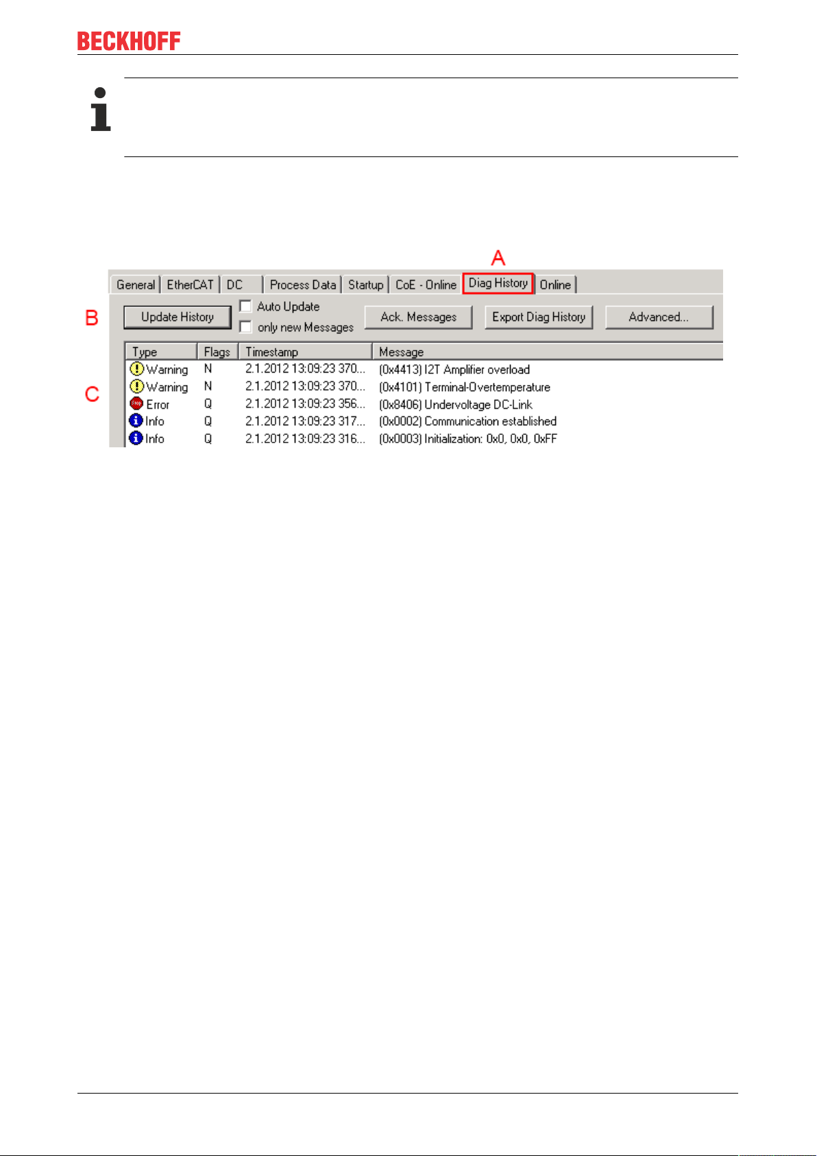
Diagnostics
Support for commissioning
The DiagMessages system is to be used above all during the commissioning of the plant. The diagnostic values e.g. in the StatusWord of the device (if available) are helpful for online diagnosis during the subsequent continuous operation.
TwinCAT System Manager implementation
From TwinCAT 2.11 DiagMessages, if available, are displayed in the device’s own interface. Operation
(collection, confirmation) also takes place via this interface.
Fig.97: Implementation of the DiagMessage system in the TwinCAT System Manager
The operating buttons (B) and the history read out (C) can be seen on the Diag History tab (A). The
components of the message:
• Info/Warning/Error
• Acknowledge flag (N = unconfirmed, Q = confirmed)
• Time stamp
• Text ID
• Plain text message according to ESI/XML data
The meanings of the buttons are self-explanatory.
DiagMessages within the ADS Logger/Eventlogger
Since TwinCAT 3.1 build 4022 DiagMessages send by the terminal are shown by the TwinCAT ADS Logger.
Given that DiagMessages are represented IO- comprehensive at one place, commissioning will be
simplified. In addition, the logger output could be stored into a data file – hence DiagMessages are available
long-term for analysis.
Reading messages into the PLC
- In preparation -
Interpretation
Time stamp
The time stamp is obtained from the local clock of the terminal at the time of the event. The time is usually
the distributed clock time (DC) from register x910.
Please note: When EtherCAT is started, the DC time in the reference clock is set to the same time as the
local IPC/TwinCAT time. From this moment the DC time may differ from the IPC time, since the IPC time is
not adjusted. Significant time differences may develop after several weeks of operation without a EtherCAT
restart. As a remedy, external synchronization of the DC time can be used, or a manual correction
calculation can be applied, as required: The current DC time can be determined via the EtherCAT master or
from register x901 of the DC slave.
EL5042 99Version: 1.5
Page 100

Diagnostics
Structure of the Text ID
The structure of the MessageID is not subject to any standardization and can be supplier-specifically
defined. In the case of Beckhoff EtherCAT devices (EL, EP) it usually reads according to xyzz:
x y zz
0: Systeminfo
2: reserved
1: Info
4: Warning
8: Error
Example: Message 0x4413 --> Drive Warning Number 0x13
Overview of text IDs
Specific text IDs are listed in the device documentation.
0: System
1: General
2: Communication
3: Encoder
4: Drive
5: Inputs
6: I/O general
7: reserved
Error number
EL5042100 Version: 1.5
 Loading...