

Page 1

Documentation | EN
EL37x2
2 channel Analog Input Terminals with oversampling
2021-03-11 | Version: 3.8
Page 2

Page 3

Product overview analog input terminals with oversampling
1 Product overview analog input terminals with
oversampling
EL3702 [}16]
Two-channel analog input terminal, -10V … +10V with oversampling
EL3702-0015 [}16]
Two-channel analog input terminal, -150mV … +150mV with oversampling
EL3742 [}19]
Two-channel analog input terminal, 0 … 20mA with oversampling
EL37x2 3Version: 3.8
Page 4

Table of contents
Table of contents
1 Product overview analog input terminals with oversampling...............................................................3
2 Foreword ....................................................................................................................................................7
2.1 Documentation issue status ..............................................................................................................7
2.2 Notes on the documentation..............................................................................................................8
2.3 Safety instructions .............................................................................................................................9
2.4 Version identification of EtherCAT devices .....................................................................................10
2.4.1 Beckhoff Identification Code (BIC)................................................................................... 14
3 Product overview.....................................................................................................................................16
3.1 EL3702 - Introduction ......................................................................................................................16
3.2 EL3702 - Technical data..................................................................................................................18
3.3 EL3742 - Introduction ......................................................................................................................19
3.4 EL3742 - Technical data..................................................................................................................20
3.5 Basic function principles ..................................................................................................................21
3.6 Sample programs ............................................................................................................................25
4 Basics communication ...........................................................................................................................30
4.1 EtherCAT basics..............................................................................................................................30
4.2 EtherCAT cabling – wire-bound.......................................................................................................30
4.3 General notes for setting the watchdog...........................................................................................31
4.4 EtherCAT State Machine.................................................................................................................33
4.5 CoE - Interface: notes......................................................................................................................34
4.6 Distributed Clock .............................................................................................................................35
5 Mounting and wiring................................................................................................................................36
5.1 Instructions for ESD protection........................................................................................................36
5.2 Installation on mounting rails ...........................................................................................................36
5.3 Installation instructions for enhanced mechanical load capacity .....................................................39
5.4 Connection system ..........................................................................................................................40
5.5 Installation positions ........................................................................................................................43
5.6 Positioning of passive Terminals .....................................................................................................45
5.7 ATEX - Special conditions (extended temperature range) ..............................................................46
5.8 IECEx - Special conditions ..............................................................................................................47
5.9 Continuative documentation for ATEX and IECEx ..........................................................................48
5.10 cFMus - Special conditions..............................................................................................................49
5.11 Continuative documentation for cFMus ...........................................................................................50
5.12 UL notice .........................................................................................................................................51
5.13 Configuration of 0/4..20 mA differential inputs.................................................................................52
5.14 EL37x2 - LEDs and pin assignment ................................................................................................56
5.14.1 EL37x2 - LEDs................................................................................................................. 56
5.14.2 EL37x2 - Pin assignment................................................................................................. 57
6 Commissioning........................................................................................................................................60
6.1 TwinCAT Quick Start .......................................................................................................................60
6.1.1 TwinCAT 2 ....................................................................................................................... 63
6.1.2 TwinCAT 3 ....................................................................................................................... 73
6.2 TwinCAT Development Environment ..............................................................................................86
EL37x24 Version: 3.8
Page 5

Table of contents
6.2.1 Installation of the TwinCAT real-time driver..................................................................... 87
6.2.2 Notes regarding ESI device description........................................................................... 92
6.2.3 TwinCAT ESI Updater ..................................................................................................... 96
6.2.4 Distinction between Online and Offline............................................................................ 96
6.2.5 OFFLINE configuration creation ...................................................................................... 97
6.2.6 ONLINE configuration creation ...................................................................................... 102
6.2.7 EtherCAT subscriber configuration................................................................................ 110
6.2.8 Import/Export of EtherCAT devices with SCI and XTI ................................................... 119
6.3 General Notes - EtherCAT Slave Application................................................................................125
6.4 Oversampling terminals/boxes and TwinCAT Scope ....................................................................133
6.4.1 TwinCAT 3 procedure.................................................................................................... 134
6.4.2 TwinCAT 2 procedure.................................................................................................... 143
6.5 Process data and configuration .....................................................................................................151
6.5.1 TwinCAT tree................................................................................................................. 151
6.5.2 Extent of process data in delivery state ......................................................................... 153
6.5.3 Oversampling settings, distributed clocks (DC) ............................................................. 157
6.6 Basics about signal isolators, barriers ...........................................................................................163
6.7 Notices on analog specifications ...................................................................................................166
6.7.1 Full scale value (FSV).................................................................................................... 166
6.7.2 Measuring error/ measurement deviation ...................................................................... 166
6.7.3 Temperature coefficient tK [ppm/K] ............................................................................... 167
6.7.4 Long-term use................................................................................................................ 168
6.7.5 Single-ended/differential typification .............................................................................. 168
6.7.6 Common-mode voltage and reference ground (based on differential inputs)................ 173
6.7.7 Dielectric strength .......................................................................................................... 173
6.7.8 Temporal aspects of analog/digital conversion.............................................................. 174
7 Appendix ................................................................................................................................................177
7.1 EtherCAT AL Status Codes...........................................................................................................177
7.2 Firmware information for EL37xx/EL47xx......................................................................................177
7.3 Firmware compatibility...................................................................................................................178
7.4 Firmware Update EL/ES/EM/ELM/EPxxxx ....................................................................................178
7.4.1 Device description ESI file/XML..................................................................................... 180
7.4.2 Firmware explanation .................................................................................................... 183
7.4.3 Updating controller firmware *.efw................................................................................. 184
7.4.4 FPGA firmware *.rbf....................................................................................................... 185
7.4.5 Simultaneous updating of several EtherCAT devices.................................................... 189
7.5 Support and Service ......................................................................................................................190
EL37x2 5Version: 3.8
Page 6

Table of contents
EL37x26 Version: 3.8
Page 7

2 Foreword
2.1 Documentation issue status
Version Comment
3.8 • Update chapter “Technical data”
• Chapter "Commissioning": addenda subchapter "Basics about signal isolators, barriers"
• Update chapter "Configuration of 0/4..20 mA differential inputs
• Update structure
• Update revision status
3.7 • Update chapter "Technical data"
• Update structure
• Update revision status
3.6 • EL3702-0015 added
• Update structure
• Update revision status
3.5 • Update chapter "Sample programs"
• Update structure
3.4 • Update chapter "Technical data"
• Chapter "ATEX - Special conditions" replaced with chapter "ATEX - Special conditions (extended
temperature range)"
• Addenda chapter "Instructions for ESD protection"
• Update chapter "Notices on Analog specification"
• Update revision status
3.3 • Update chapter "Product overview"
• Addenda chapter “Notices on analog specifications”
3.2 • Update chapter "Notes on the documentation"
• Update of Technical data
• Addenda chapter "TwinCAT Quick Start"
• Update revision status
3.1 • Section “Oversampling terminals and TwinCAT Scope” added
3.0 • Migration
2.0 • Update chapter "Technical data"
• Addenda chapter "Installation instructions for enhanced mechanical load capacity"
• Update structure
• Update revision status
1.9 • Update structure
• “Technical data” section updated
1.8 • Structural update
• Technical data updated
• Section "Configuration of 0/4..20 mA differential inputs" amended
1.7 • Technical notes added
1.6 • Technical notes example program amended
1.5 • Example program amended
1.4 • EL3742 amended
1.3 • Examples amended
1.2 • Technical data and safety instructions amended
1.1 • Technical data amended
1.0 • Technical data amended
0.1 • Provisional documentation for EL37x2
Foreword
EL37x2 7Version: 3.8
Page 8

Foreword
2.2 Notes on the documentation
Intended audience
This description is only intended for the use of trained specialists in control and automation engineering who
are familiar with the applicable national standards.
It is essential that the documentation and the following notes and explanations are followed when installing
and commissioning these components.
It is the duty of the technical personnel to use the documentation published at the respective time of each
installation and commissioning.
The responsible staff must ensure that the application or use of the products described satisfy all the
requirements for safety, including all the relevant laws, regulations, guidelines and standards.
Disclaimer
The documentation has been prepared with care. The products described are, however, constantly under
development.
We reserve the right to revise and change the documentation at any time and without prior announcement.
No claims for the modification of products that have already been supplied may be made on the basis of the
data, diagrams and descriptions in this documentation.
Trademarks
Beckhoff®, TwinCAT®, EtherCAT®, EtherCATG®, EtherCATG10®, EtherCATP®, SafetyoverEtherCAT®,
TwinSAFE®, XFC®, XTS® and XPlanar® are registered trademarks of and licensed by Beckhoff Automation
GmbH. Other designations used in this publication may be trademarks whose use by third parties for their
own purposes could violate the rights of the owners.
Patent Pending
The EtherCAT Technology is covered, including but not limited to the following patent applications and
patents: EP1590927, EP1789857, EP1456722, EP2137893, DE102015105702 with corresponding
applications or registrations in various other countries.
EtherCAT® is registered trademark and patented technology, licensed by Beckhoff Automation GmbH,
Germany.
Copyright
© Beckhoff Automation GmbH & Co. KG, Germany.
The reproduction, distribution and utilization of this document as well as the communication of its contents to
others without express authorization are prohibited.
Offenders will be held liable for the payment of damages. All rights reserved in the event of the grant of a
patent, utility model or design.
EL37x28 Version: 3.8
Page 9

Foreword
2.3 Safety instructions
Safety regulations
Please note the following safety instructions and explanations!
Product-specific safety instructions can be found on following pages or in the areas mounting, wiring,
commissioning etc.
Exclusion of liability
All the components are supplied in particular hardware and software configurations appropriate for the
application. Modifications to hardware or software configurations other than those described in the
documentation are not permitted, and nullify the liability of Beckhoff Automation GmbH & Co. KG.
Personnel qualification
This description is only intended for trained specialists in control, automation and drive engineering who are
familiar with the applicable national standards.
Description of instructions
In this documentation the following instructions are used.
These instructions must be read carefully and followed without fail!
DANGER
Serious risk of injury!
Failure to follow this safety instruction directly endangers the life and health of persons.
WARNING
Risk of injury!
Failure to follow this safety instruction endangers the life and health of persons.
CAUTION
Personal injuries!
Failure to follow this safety instruction can lead to injuries to persons.
NOTE
Damage to environment/equipment or data loss
Failure to follow this instruction can lead to environmental damage, equipment damage or data loss.
Tip or pointer
This symbol indicates information that contributes to better understanding.
EL37x2 9Version: 3.8
Page 10

Foreword
2.4 Version identification of EtherCAT devices
Designation
A Beckhoff EtherCAT device has a 14-digit designation, made up of
• family key
• type
• version
• revision
Example Family Type Version Revision
EL3314-0000-0016 EL terminal
(12 mm, nonpluggable connection
level)
ES3602-0010-0017 ES terminal
(12 mm, pluggable
connection level)
CU2008-0000-0000 CU device 2008 (8-port fast ethernet switch) 0000 (basic type) 0000
3314 (4-channel thermocouple
terminal)
3602 (2-channel voltage
measurement)
0000 (basic type) 0016
0010 (highprecision version)
0017
Notes
• The elements mentioned above result in the technical designation. EL3314-0000-0016 is used in the
example below.
• EL3314-0000 is the order identifier, in the case of “-0000” usually abbreviated to EL3314. “-0016” is the
EtherCAT revision.
• The order identifier is made up of
- family key (EL, EP, CU, ES, KL, CX, etc.)
- type (3314)
- version (-0000)
• The revision -0016 shows the technical progress, such as the extension of features with regard to the
EtherCAT communication, and is managed by Beckhoff.
In principle, a device with a higher revision can replace a device with a lower revision, unless specified
otherwise, e.g. in the documentation.
Associated and synonymous with each revision there is usually a description (ESI, EtherCAT Slave
Information) in the form of an XML file, which is available for download from the Beckhoff web site.
From 2014/01 the revision is shown on the outside of the IP20 terminals, see Fig. “EL5021 EL terminal,
standard IP20 IO device with batch number and revision ID (since 2014/01)”.
• The type, version and revision are read as decimal numbers, even if they are technically saved in
hexadecimal.
Identification number
Beckhoff EtherCAT devices from the different lines have different kinds of identification numbers:
Production lot/batch number/serial number/date code/D number
The serial number for Beckhoff IO devices is usually the 8-digit number printed on the device or on a sticker.
The serial number indicates the configuration in delivery state and therefore refers to a whole production
batch, without distinguishing the individual modules of a batch.
Structure of the serial number: KKYYFFHH
KK - week of production (CW, calendar week)
YY - year of production
FF - firmware version
HH - hardware version
EL37x210 Version: 3.8
Page 11
Foreword
Example with
Ser. no.: 12063A02: 12 - production week 12 06 - production year 2006 3A - firmware version 3A 02 hardware version 02
Exceptions can occur in the IP67 area, where the following syntax can be used (see respective device
documentation):
Syntax: D ww yy x y z u
D - prefix designation
ww - calendar week
yy - year
x - firmware version of the bus PCB
y - hardware version of the bus PCB
z - firmware version of the I/O PCB
u - hardware version of the I/O PCB
Example: D.22081501 calendar week 22 of the year 2008 firmware version of bus PCB: 1 hardware version
of bus PCB: 5 firmware version of I/O PCB: 0 (no firmware necessary for this PCB) hardware version of I/O
PCB: 1
Unique serial number/ID, ID number
In addition, in some series each individual module has its own unique serial number.
See also the further documentation in the area
• IP67: EtherCAT Box
• Safety: TwinSafe
• Terminals with factory calibration certificate and other measuring terminals
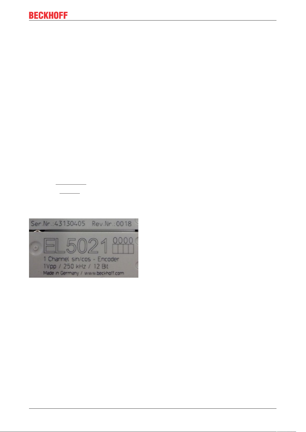
Examples of markings
Fig.1: EL5021 EL terminal, standard IP20 IO device with serial/ batch number and revision ID (since
2014/01)
EL37x2 11Version: 3.8
Page 12
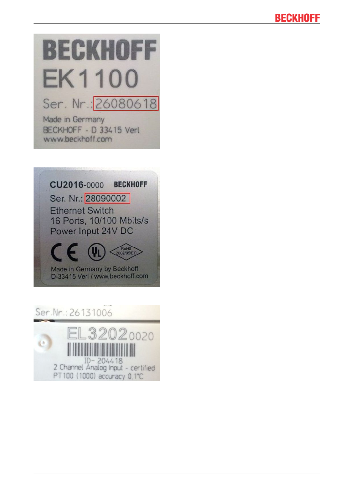
Foreword
Fig.2: EK1100 EtherCAT coupler, standard IP20 IO device with serial/ batch number
Fig.3: CU2016 switch with serial/ batch number
Fig.4: EL3202-0020 with serial/ batch number 26131006 and unique ID-number 204418
EL37x212 Version: 3.8
Page 13
Foreword
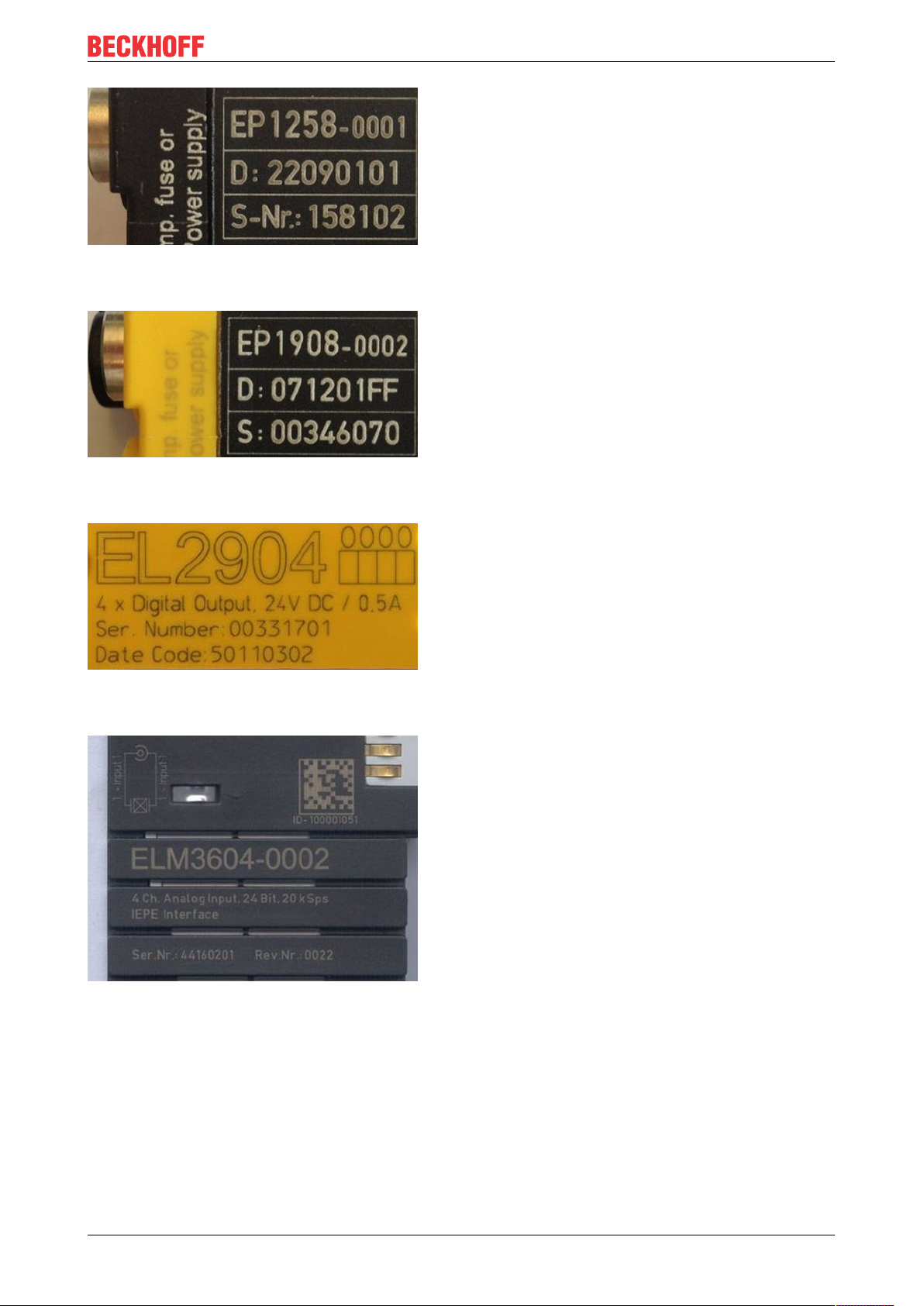
Fig.5: EP1258-00001 IP67 EtherCAT Box with batch number/ date code 22090101 and unique serial
number 158102
Fig.6: EP1908-0002 IP67 EtherCAT Safety Box with batch number/ date code 071201FF and unique serial
number 00346070
Fig.7: EL2904 IP20 safety terminal with batch number/ date code 50110302 and unique serial number
00331701
Fig.8: ELM3604-0002 terminal with unique ID number (QR code) 100001051 and serial/ batch number
44160201
EL37x2 13Version: 3.8
Page 14
Foreword
2.4.1 Beckhoff Identification Code (BIC)
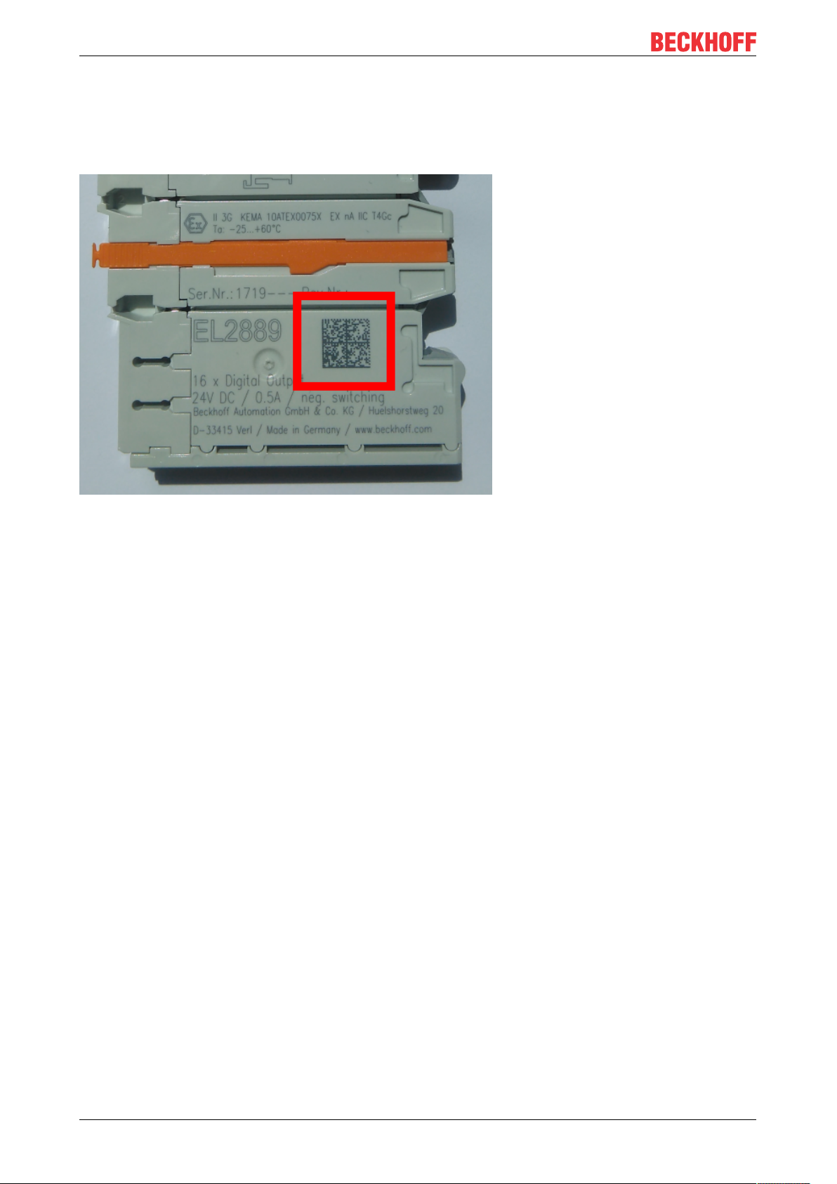
The Beckhoff Identification Code (BIC) is increasingly being applied to Beckhoff products to uniquely identify
the product. The BIC is represented as a Data Matrix Code (DMC, code scheme ECC200), the content is
based on the ANSI standard MH10.8.2-2016.
Fig.9: BIC as data matrix code (DMC, code scheme ECC200)
The BIC will be introduced step by step across all product groups.
Depending on the product, it can be found in the following places:
• on the packaging unit
• directly on the product (if space suffices)
• on the packaging unit and the product
The BIC is machine-readable and contains information that can also be used by the customer for handling
and product management.
Each piece of information can be uniquely identified using the so-called data identifier
(ANSIMH10.8.2-2016). The data identifier is followed by a character string. Both together have a maximum
length according to the table below. If the information is shorter, spaces are added to it. The data under
positions 1 to 4 are always available.
The following information is contained:
EL37x214 Version: 3.8
Page 15

Item
Type of
no.
information
1 Beckhoff order
number
2 Beckhoff Traceability
Number (BTN)
3 Article description Beckhoff article
4 Quantity Quantity in packaging
5 Batch number Optional: Year and week
6 ID/serial number Optional: Present-day
7 Variant number Optional: Product variant
...
Explanation Data
Beckhoff order number 1P 8 1P072222
Unique serial number,
see note below
description, e.g.
EL1008
unit, e.g. 1, 10, etc.
of production
serial number system,
e.g. with safety products
or calibrated terminals
number on the basis of
standard products
Foreword
Number of digits
identifier
S 12 SBTNk4p562d7
1K 32 1KEL1809
Q 6 Q1
2P 14 2P401503180016
51S 12 51S678294104
30P 32 30PF971, 2*K183
incl. data identifier
Example
Further types of information and data identifiers are used by Beckhoff and serve internal processes.
Structure of the BIC
Example of composite information from item 1 to 4 and 6. The data identifiers are marked in red for better
display:
BTN
An important component of the BIC is the Beckhoff Traceability Number (BTN, item no.2). The BTN is a
unique serial number consisting of eight characters that will replace all other serial number systems at
Beckhoff in the long term (e.g. batch designations on IO components, previous serial number range for
safety products, etc.). The BTN will also be introduced step by step, so it may happen that the BTN is not yet
coded in the BIC.
NOTE
This information has been carefully prepared. However, the procedure described is constantly being further
developed. We reserve the right to revise and change procedures and documentation at any time and without prior notice. No claims for changes can be made from the information, illustrations and descriptions in
this information.
EL37x2 15Version: 3.8
Page 16
Product overview
3 Product overview
3.1 EL3702 - Introduction
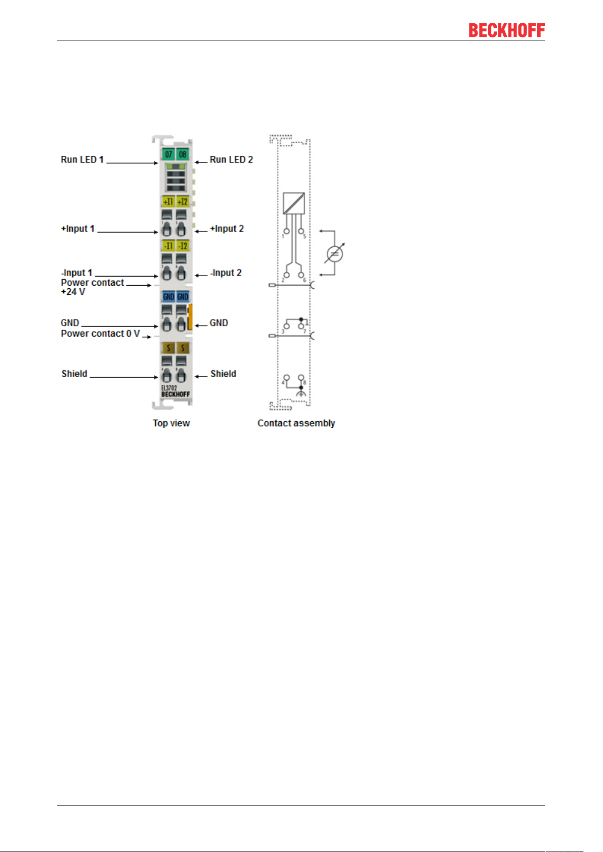
Fig.10: EL3702
Two-channel analog input terminal, differential inputs, -10V … +10V with oversampling
The EL3702 analog input terminal handles signals in the range from -10 V to +10 V. The voltage is digitized
to a resolution of 16 bits, and is transmitted, electrically isolated, to the controller. The input channels of the
EtherCAT Terminals have differential inputs and possess a common, internal ground potential.
The signals are sampled with a configurable, integer multiple (oversampling factor: n) of the bus cycle time
(n microcycles per EtherCAT bus cycle). The EtherCAT Terminal generates a set of n process data per
channel for each EtherCAT bus cycle, which is accumulated and transferred in the next bus cycle. The
timebase of the terminal can be synchronized precisely with other EtherCAT devices via distributed clocks.
This procedure enables the temporal resolution of the analog input signals to be increased to n times the bus
cycle time.
Responses at equidistant intervals are made possible in conjunction with the EL4702/EL4732 (analog output
terminal with oversampling) or any other distributed clocks-capable EtherCAT device.
The maximum sampling rate of the EL3702 is 100ksps (10µs sampling) at a recommended input signal
bandwidth of 0..30kHz.
Information on the distributed clocks can be found in the separate System description.
The EL3702-0015 analog input terminal is also available for signals in the range from -150 mV to + 150 mV.
EL37x216 Version: 3.8
Page 17

Quick links
• EtherCAT basics
• Basic function principles [}21]
• Process data and configuration [}151]
Product overview
EL37x2 17Version: 3.8
Page 18

Product overview
3.2 EL3702 - Technical data
Technical data EL3702 EL3702-0015
Number of inputs 2
Signal voltage -10V ... +10V -150mV ... +150mV
Max. sampling rate max. 10 µs/100 kSps (per channel, simultaneous)
Oversampling factor n = integer multiple of the EtherCAT cycle time, 1..100
Input signal bandwidth 0...30kHz (recommended)
Distributed Clocks precision < 100ns
Internal resistance >200kΩ
Common-mode voltage U
Dielectric strength differential max. 35V
Resolution 16bit
Conversion time ~ 10µs
Measuring error < ± 0.3%
Electrical isolation 500V (E-bus/field voltage)
Supply voltage for electronics via the E-bus
Current consumption via E-bus typ. 200mA
Bit width in process image Input: n x 2 x 16bit data, 2 x 16bit CycleCounter if applicable, 4bytes StartNext-
Configuration via TwinCAT System Manager
Weight approx. 60g
Permissible ambient temperature range during operation
Permissible ambient temperature range during storage
Permissible relative humidity 95%, no condensation
Dimensions (W x H x D) approx. 15mm x 100mm x 70mm (width aligned: 12mm)
Mounting on 35mm mounting rail conforms to EN 60715
Vibration/shock resistance conforms to EN 60068-2-6 / EN
EMC immunity/emission conforms to EN 61000-6-2 / EN 61000-6-4
Protection class IP20
Installation position variable
Approval CE, EAC
CM
max. 35V
(at 25°C ... +55°C,
based on the full-scale value, at < 10Hz input signal)
< ± 0.5%
(when the extended temperature range is
used)
LatchTime if applicable
-25°C ... +60°C
(extended temperature range)
-40°C ... +85°C -25°C ... +85°C
60068-2-27,
see also installation instructions for enhanced mechanical load capacity
ATEX [}46]
IECEx [}47]
cULus [}51]
cFMus [}49]
< ± 0.3%
(based on the full-scale value, at < 10Hz
input signal)
0°C ... +55°C
conforms to EN 60068-2-6 / EN 60068-2-27
CE
Ex markings
Standard Marking
ATEX II 3 G Ex nA IIC T4 Gc
II 3 D Ex tc IIIC T135 °C Dc
IECEx Ex nA IIC T4 Gc
Ex tc IIIC T135 °C Dc
cFMus Class I, Division 2, Groups A, B, C, D
Class I, Zone 2, AEx ec IIC T4 Gc
EL37x218 Version: 3.8
Page 19
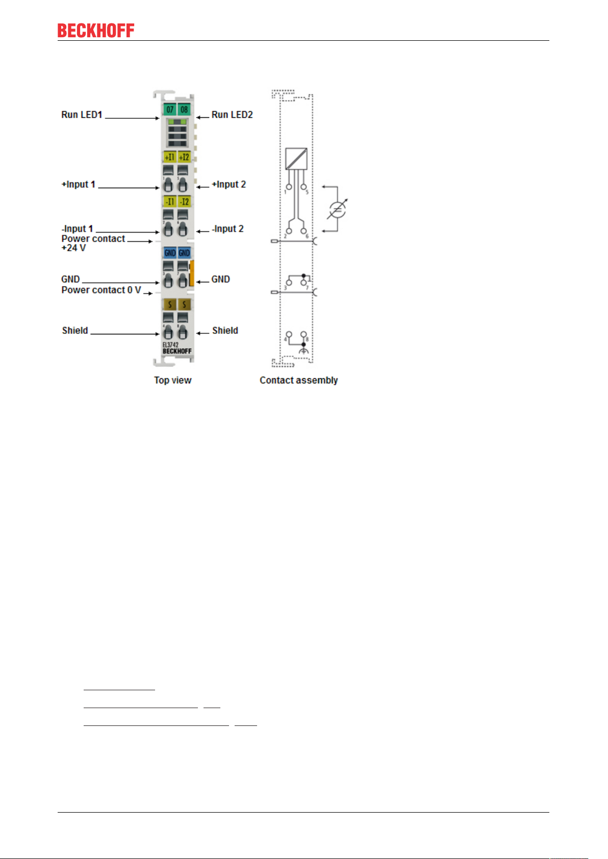
3.3 EL3742 - Introduction
Product overview
Fig.11: EL3742
Two-channel analog input terminal, differential inputs, 0...20mA with oversampling
The EL3742 analog input terminal handles signals in the range from 0 to 20 mA. The voltage is digitized to a
resolution of 16 bits, and is transmitted, electrically isolated, to the controller. The input channels of the
EtherCAT Terminals have differential inputs and possess a common, internal ground potential.
The signals are sampled with a configurable, integer multiple (oversampling factor: n) of the bus cycle time
(n microcycles per EtherCAT bus cycle). The EtherCAT Terminal generates a set of n process data per
channel for each EtherCAT bus cycle, which is accumulated and transferred in the next bus cycle. The
timebase of the terminal can be synchronized precisely with other EtherCAT devices via distributed clocks.
This procedure enables the temporal resolution of the analog input signals to be increased to n times the bus
cycle time.
Responses at equidistant intervals are made possible in conjunction with the EL4702/EL4732 (analog output
terminal with oversampling) or any other distributed clocks-capable EtherCAT device.
The maximum sampling rate of the EL3742 is 100ksps (10µs sampling) at a recommended input signal
bandwidth of 0..30kHz.
Information on the distributed clocks can be found in the separate System description.
Quick links
• EtherCAT basics
• Basic function principles [}21]
• Process data and configuration [}151]
EL37x2 19Version: 3.8
Page 20

Product overview
3.4 EL3742 - Technical data
Technical data EL3742
Number of inputs 2
Signal voltage 0mA…20mA
Max. sampling rate max. 10 µs/100 kSps (per channel, simultaneous)
Oversampling factor n = integer multiple of the EtherCAT cycle time, 1..100
Input signal bandwidth 0...30kHz (recommended)
Distributed Clocks precision < 100ns
Internal resistance 85Ω typ. + diode voltage
Resolution 16bit
Conversion time ~ 10µs
Measuring error < ± 0.3% (at 25°C ... +55°C,
based on the full-scale value, at < 10Hz input signal)
< ± 0.5% (when the extended temperature range is used)
Electrical isolation 500V (E-bus/field voltage)
Supply voltage for electronics via the E-bus
Current consumption via Ebus
Bit width in process image Input: n x 2 x 16bit data, 2 x 16bit CycleCounter if applicable, 4bytes
Configuration via TwinCAT System Manager
Weight approx. 60g
Permissible ambient
temperature range during
operation
Permissible ambient
temperature range during
storage
Permissible relative humidity 95%, no condensation
Dimensions (W x H x D) approx. 15mm x 100mm x 70mm (width aligned: 12mm)
Mounting [}36]
Vibration/shock resistance conforms to EN 60068-2-6 / EN 60068-2-27,
EMC immunity/emission conforms to EN 61000-6-2 / EN 61000-6-4
Protection class IP20
Installation position variable
Approval CE
typ. 200mA
StartNextLatchTime if applicable
-25°C ... +60°C (extended temperature range)
-40°C ... +85°C
on 35mm mounting rail conforms to EN 60715
see also installation instructions [}39] for enhanced mechanical load
capacity
ATEX [}46]
cULus [}51]
Ex markings
Standard Marking
ATEX II 3 G Ex nA IIC T4 Gc
EL37x220 Version: 3.8
Page 21

Product overview
3.5 Basic function principles
The analog EL3702/ EL3742 input terminal enables measurement of two voltages/currents, which can be
displayed with a resolution of 16bit (65535steps).
The oversampling feature enables the terminal to sample analog input values several times during each bus
cycle on each channel.
Oversampling
A conventional analog input terminal samples one analog input value ("sample") during each bus cycle and
transfers it to the higher-level control system during the next fieldbus cycle. The EL37x2 samples the voltage
several times between two fieldbus communication cycles configurable and at equidistant intervals. A 16-bit
packet of x analog measured values is transferred to the higher-level control system during the next fieldbus
communication cycle. This procedure is referred to as oversampling.
Distributed Clock
Oversampling requires a clock generator in the terminal that triggers the individual data sampling events.
The local clock in the terminal, referred to as distributed clock, is used for this purpose.
The distributed clock represents a local clock in the EtherCAT slave controller (ESC) with the following
characteristics:
• Unit 1 ns.
• Zero point 1.1.2000 00:00.
• Size 64 bit (sufficient for the next 584 years); however, some EtherCAT slaves only offer 32-bit
support, i.e. the variable overflows after approx. 4.2 seconds.
• The EtherCAT master automatically synchronizes the local clock with the master clock in the EtherCAT
bus with a precision of < 100 ns.
The EL37x2 only offers 32-bit support.
Sample:
The fieldbus/EtherCAT master is operated with a cycle time of 1 ms to match the higher-level PLC cycle time
of 1 ms, for example. This means that every 1 ms an EtherCAT frame is sent to collect the process data from
the EL37x2. The local terminal clock therefore triggers an interrupt in the ESC every 1 ms (1 kHz), in order to
make the process data available in time for collection by the EtherCAT frame. This first interrupt is called
SYNC1.
The EL37x2 may be set to oversampling n = 10 in the TwinCAT System Manager. This causes the ESC to
generate a second interrupt in the terminal with an n-times higher frequency, in this case 10 kHz or 100 µs
period. This interrupt is called SYNC0. At each SYNC0 signal the analog-to-digital converter (ADC) starts a
data sampling event, and the sampled analog values are sequentially stored in a buffer.
Determining the input voltages/input currents
Both input voltages / input currents (channels 1 and 2) are always sampled simultaneously. This is
ensured by the ADC type that is triggered by the SYNC0 pulse. No other operation mode is possible.
Generation of the SYNC0 pulse from the local synchronized clock within the distributed clock network
ensures that the analog values are sampled at highly equidistant intervals with the period of the SYNC1
pulse.
The maximum oversampling factor depends on the memory size of the used ESC and in the KKYY0000
version of the EL37x2, it is n = 100.
EL37x2 21Version: 3.8
Page 22

Product overview
Maximum sampling frequency
A smaller period than 10 µs is not permitted for the EL37x2. The maximum sampling frequency for
the EL37x2 is therefore 100 kSps (samples per second).
Regarding the calculation of SYNC0 from the SYNC1 pulse based on manual specification of an
oversampling factor, please note that for SYNC0 only integer values are calculated at nanosecond
intervals.
Sample: 187,500 µs is permitted, 333.3 is not.
Sample:
For SYNC1 = 1 ms oversampling factors such as 1,2,5 or 100 are permitted, but not 3! If implausible values
are use the terminal will reach the OP state but will not supply any process data. This may result in a working
counter error.
The 16-bit measured values accumulated in the buffer are sent as a packet to the higher-level control
system. For two channels and n = 100, 2 x 2 x 100 = 400 bytes of process data are transferred during each
EtherCAT cycle.
Time-related cooperation with other terminals
ADC data sampling in the EL37x2 is triggered by an interrupt that is generated by the local clock in the
terminal. All local clocks in the supporting EtherCAT slaves are synchronized. This enables EtherCAT slaves
(here: terminals) to sample measured values simultaneously (simultaneous interrupt generation),
independent of the distance between them. This simultaneity is within the distributed clock precision range of
< 100 ns.
Sample:
Matching between two EL37x2:
The EtherCAT master, e.g. Beckhoff TwinCAT, configures both EL37x2 such that their SYNC1 signals occur
at the same time. Assumption: The EtherCAT bus cycle time is 500 µs. SYNC1 is therefore triggered every
500 µs in all EL37x2. If both terminals operate with a corresponding oversampling factor (e.g. 20), the
SYNC0 pulse correlating to SYNC1 will occur simultaneously in all EL37x2, in this example every 25 µs. One
application option would be "distributed" oscilloscope with a sampling frequency of 40 kSps, for example.
If the EL37x2 use different oversampling factors, their SYNC0 pulses no longer occur simultaneously. The
higher-level SYNC1 pulse is retained.
If a value is entered under "Shift time (µs)" in the TwinCAT System Manager (DC tab, Advanced Settings) for
the SYNC0 pulse in an EL37x2, the EL37x2 manipulated in this way will start output sooner or later,
according to the set value. This can be useful in cases where a wanted signal has to be sampled at a higher
frequency than the 100 kSps permitted for the EL37x2, and several interconnected EL37x2 are therefore
used.
Sample:
For sampling a wanted signal at 200 kSps two EL37x2 are used side-by-side and subjected to the same
wanted signal (e.g. channel 1 in both terminals). Assume a bus cycle of 1 ms, an oversampling factor in both
EL37x2 of n = 100, and therefore maximum speed at 10 µs interval or 100 kSps. In the second EL37x2 an
additional Shift Time of 5 µs is entered manually for this terminal in the System Manager (DC tab, Advanced
Settings, SYNC0, User Defined). This means all SYNC0 pulses for this EL37x2 will occur 5 µs later than for
the first EL37x2.
Synchronization and provision of process data
Since the SYNC1 pulse is derived from the SYNC0 pulse, each SYNC1 pulse of the second EL37x2
will occur 5 µs after the SYNC1 pulse of the first EL37x2. Please note that this may influence the
timing of the process data allocation for the EtherCAT frame, since this is controlled by the SYNC1
pulse.
EL37x222 Version: 3.8
Page 23
Product overview
Each terminal now transfers a 400 byte process data packet to the higher-level control system. If these two
data sets (which are offset by 5 µs) with a length of 1 ms each are sorted in the right chronological order in
the control system, the wanted signal is transparently sampled at 200 kSps.
The application of these functions using the Beckhoff TwinCAT System Manager is described in section
Process data and configuration [}151].
SYNC0 and SYNC1 pulse with several EtherCAT slaves
This approach of matching the SYNC0 and SYNC1 pulses of several EtherCAT slaves is not limited
to EL37x2.
All EtherCAT slaves supporting the distributed clock function can be correlated relatively freely in
this way.
NOTE
Attention! Risk of device damage!
The above notes and information should be used advisedly.
The EtherCAT master automatically allocates SYNC0 and SYNC1 settings that support reliable and timely
process data acquisition.
User intervention at this point may lead to undesired behavior.
If these settings are changed in the System Manager, no plausibility checks are carried out on the software
side.
Correct function of the terminal with all conceivable setting options cannot be guaranteed.
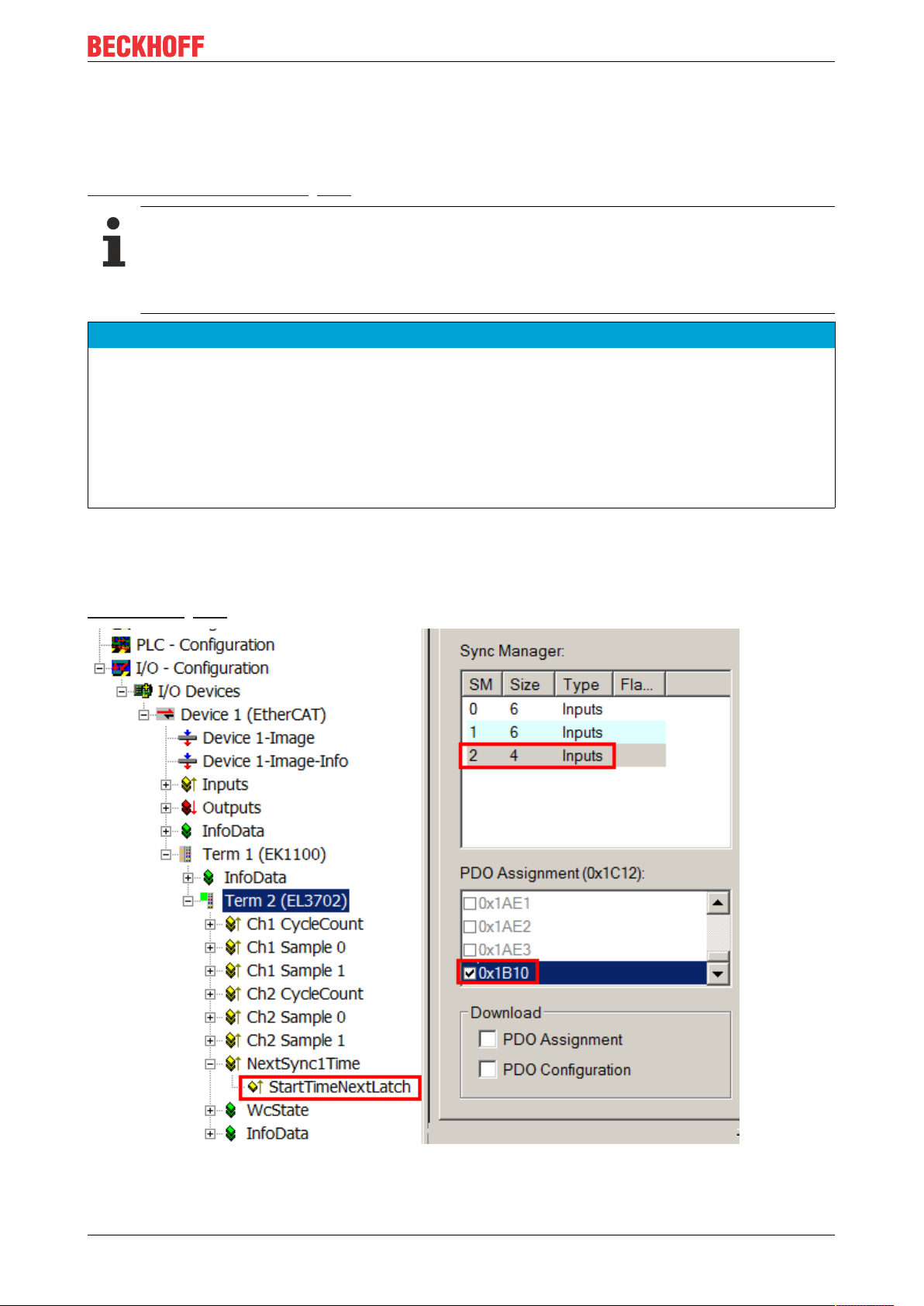
Timestamp of the process data
The EL37xx can provide a "timestamp" for each process data block, if required. This process record can be
activated as StartTimeNextLatch, a as 32-bit value, by activating 0x1B10 in the Process Data tab, see also
Process Data [}151] page.
Fig.12: Optional process record StartTimeNextLatch
EL37x2 23Version: 3.8
Page 24
Product overview
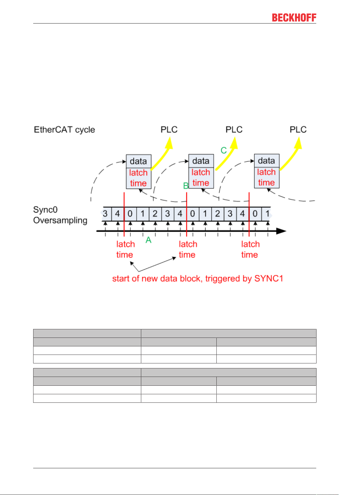
As the name suggests, the data block consisting of sample value+timestamp, which is transferred in each
cycle, is not related. The relationship is shown in Fig. Temporal relationship between SYNC signals and
SyncManager interrupt. To explain in more detail:
• the example is based on an oversampling factor of 5
• The SYNC0 signal in the terminal triggers the AD conversion and fills the internal buffer with 5
measured values (A).
• SYNC1, which triggers the filled buffer to be made available as process record and at the same time
fetches the StartTimeNextLatch from the local distributed clock (B), runs synchronous with the cycle
time.
• The data block is linked with the next but one LatchTime.
• The next EtherCAT cycle fetches this data (C).
Fig.13: Temporal relationship between SYNC signals and SyncManager interrupt
Process data
Analog values are represented as follows:
Input signal Value
EL3702 Decimal Hexadecimal
-10 V -32767 0x8001
+10 V +32767 0x7FFF
Input signal Value
EL3742 Decimal Hexadecimal
0 mA 0 0x0000
20 mA +32767 0x7FFF
The terminal is adjusted during production. No further user intervention is required.
Input characteristics
The input circuit of this terminal is optimized for higher-frequency signals up to around 30kHz, i.e. the
recommended bandwidth of the wanted signal is 0Hz to 30kHz in the range -10V to +10V or 0mA to
20mA. In this frequency range the typical measuring accuracy is as follows:
EL37x224 Version: 3.8
Page 25

Product overview
< 10Hz < 0.3% of full-scale value
< 10 kHz < 1% of full-scale value
< 30 kHz < 4% of full-scale value
For wanted signals with higher frequencies the signal transducer must have adequately low impedance, in
order to prevent amplitude variations (e.g. attenuation in association with simple signal generators) leading
to incorrect measurements.
Interference from equipment
This fast analog EtherCAT Terminal may pick up high-frequency superimposed interference signals from
other equipment (e.g. proportional valves, stepper motor or DC motor output stages). In order to ensure
trouble-free operation, we recommend using separate power supply units for the terminals and the
equipment causing interference. The cables should be screened.
3.6 Sample programs
Using the example programs
This document contains sample applications of our products for certain areas of application. The
application notices provided here are based on typical features of our products and only serve as
samples. The notices contained in this document explicitly do not refer to specific applications. The
customer is therefore responsible for assessing and deciding whether the product is suitable for a
particular application. We accept no responsibility for the completeness and correctness of the
source code contained in this document. We reserve the right to modify the content of this document at any time and accept no responsibility for errors and missing information.
Diagnostics and time-stamping of analog input data
Download (https://infosys.beckhoff.com/content/1033/el37x2/Resources/zip/2445351051.zip)
In this example the input data of an EL3702 will be checked for validity and processed:
• 1 ms cycle time, 10-fold oversampling, 2 channels
• WC, State, EtherCAT Master DevState and CycleCounter are checked cyclically; the input data is only
passed on if it is valid
• Starting from the time stamp delivered with sample 0, all other samples will be given 64-bit DC time
stamps
• Default values will be passed on if the input data is invalid; time stamping continues
• The data from each cycle is placed in a FIFO buffer so that a superordinated process, e.g. an
evaluation, can take place.
Connection diagram:
EL37x2 25Version: 3.8
Page 26
Product overview
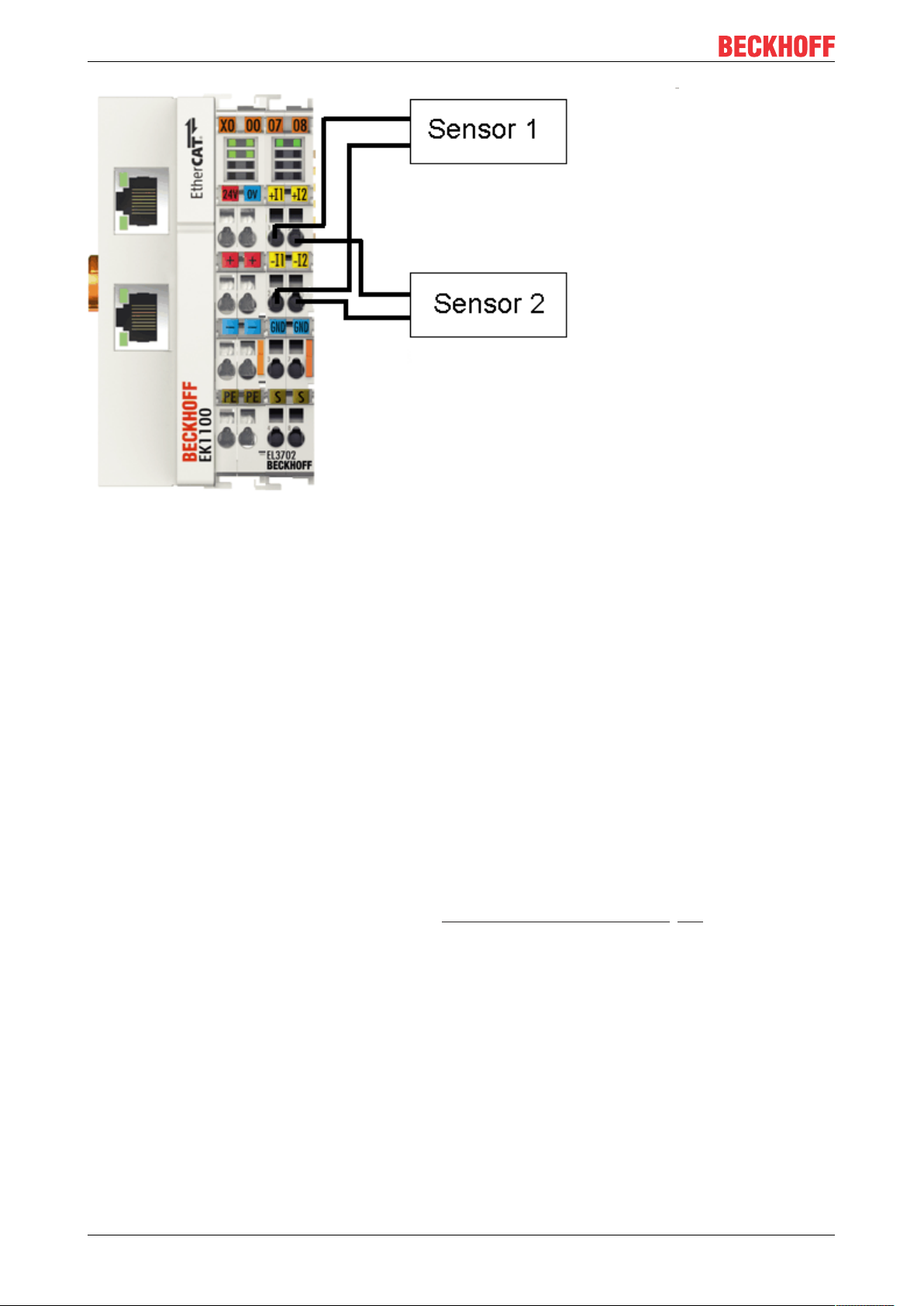
Fig.14: Connection for sample program
Starting the example program
The application samples have been tested with a test configuration and are described accordingly.
Certain deviations when setting up actual applications are possible.
The following hardware and software were used for the test configuration:
• TwinCAT master PC with Windows XP Professional SP 3, TwinCAT version 2.10 (Build 1330) and
INTEL PRO/100 VE Ethernet adapter
• Beckhoff EK1100 EtherCAT coupler, EL3702 and EL9011 terminals
• 2 x optical proximity limit switch 0 - 10V with two-wire technology
Procedure for starting the program
• After clicking the Download button, save the zip file locally on your hard disk, and unzip the *.TSM
(configuration) and the *.PRO (PLC program) files into a temporary working folder.
• The *.pro file can be opened by double click or by the TwinCAT PLC Control application with menu
selection “File/ Open”. The *.tsm file is provided for the TwinCAT System Manager (to review or
overtake configurations).
• Connect the hardware in accordance with fig. Connection for sample program [}25] and connect the
Ethernet adapter of your PC to the EtherCAT coupler (further information on this can be found in the
corresponding coupler manuals)
• Select the local Ethernet adapter (with real-time driver, if applicable) under System configuration, I/O
configuration, I/O devices, Device (EtherCAT); then on the “Adapter” tab choose “Search...”, select the
appropriate adapter and confirm (see Fig. Searching the Ethernet adapter + Selection and confirmation
of the Ethernet adapter).
EL37x226 Version: 3.8
Page 27
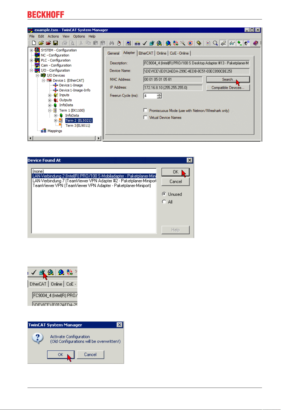
Fig.15: Searching the Ethernet adapter
Product overview
Fig.16: Selection and confirmation of the Ethernet adapter
• Activate and confirm the configuration (Fig. Activation of the configuration + Confirming the activation
of the configuration)
Fig.17: Activation of the configuration
Fig.18: Confirming the activation of the configuration
EL37x2 27Version: 3.8
Page 28
Product overview
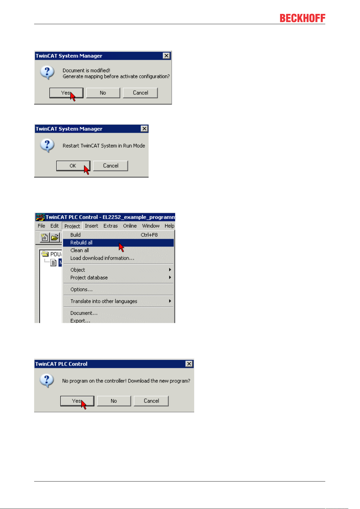
• Confirm new variable mapping, restart in RUN mode (Fig. Generate variable mapping + Restarting
TwinCAT in RUN mode)
Fig.19: Generating variable mapping
Fig.20: Restarting TwinCAT in RUN mode
• In TwinCAT PLC, under the “Project” menu, select “Rebuild all” to compile the project (Fig.Compile
project)
Fig.21: Compile project
• In TwinCAT PLC: log in with the “F11” button, confirm loading the program (Fig. Confirming program
start), run the program with the “F5” button
Fig.22: Confirming program start
Working with DC times in the controller
From the perspective of the controller the distributed clock time has the following characteristics:
• Unit 1 ns
EL37x228 Version: 3.8
Page 29

Product overview
• Universalzero point 1.1.2000 00:00, i.e. for variable evaluations an offset of 2000 years has to be
added
• Scope up to 64 bit (sufficient for 584 years). However, some EtherCAT slaves only support a 32 bit
scope, i.e. the register overflows locally after approx. 4.2 seconds and starts again at 0.
The following 3 data types are recommended for handling DC times
• T_DCTIME from TcEtherCAT.lib
This is based on T_ULARGE_INTEGER and is therefore unsigned. It can be used for linking with
suitable hardware variables
• T_ULARGE_INTEGER from TcUtilities.lib
Unsigned 64-bit data type
• T_LARGE_INTEGER from TcUtilities.lib
Signed 64-bit data type, negative numbers are represented in two's complement notation (underflow
below 0 --> 0xFFFF FFFF FFFF FFFF etc.)
TcUtilities.lib (section INT64) provides numerous relevant functions. Of particular significance are the
cast functions LARGE_TO_ULARGE and vice versa.
This type should be used when working with time differences that may be negative.
If TwinCAT is used for external synchronization, negative times will inevitably occur in the offset values.
64- vs. 32-bit representation
Some EtherCAT slaves can only handle 32 bit values for representing the DC time or handle it as a
process data. In order to prevent problems caused by overflow (every 4.2 seconds), we strongly
recommend using 64-bit times in the controller.
• 32-bit times supplied to the PLC must be complemented with the current High part
• In this case only the Low part (lower 32 bit) should be transferred to the hardware
This sample project
(https://infosys.beckhoff.com/content/1033/el37x2/Resources/zip/2469155979.zip) contains a function
block that cyclically adds the high part to a 32-bit DC time to make 64 bits.
EL37x2 29Version: 3.8
Page 30

Basics communication
4 Basics communication
4.1 EtherCAT basics
Please refer to the EtherCAT System Documentation for the EtherCAT fieldbus basics.
4.2 EtherCAT cabling – wire-bound
The cable length between two EtherCAT devices must not exceed 100 m. This results from the FastEthernet
technology, which, above all for reasons of signal attenuation over the length of the cable, allows a maximum
link length of 5 + 90 + 5 m if cables with appropriate properties are used. See also the Design
recommendations for the infrastructure for EtherCAT/Ethernet.
Cables and connectors
For connecting EtherCAT devices only Ethernet connections (cables + plugs) that meet the requirements of
at least category 5 (CAt5) according to EN 50173 or ISO/IEC 11801 should be used. EtherCAT uses 4 wires
for signal transfer.
EtherCAT uses RJ45 plug connectors, for example. The pin assignment is compatible with the Ethernet
standard (ISO/IEC 8802-3).
Pin Color of conductor Signal Description
1 yellow TD + Transmission Data +
2 orange TD - Transmission Data -
3 white RD + Receiver Data +
6 blue RD - Receiver Data -
Due to automatic cable detection (auto-crossing) symmetric (1:1) or cross-over cables can be used between
EtherCAT devices from Beckhoff.
Recommended cables
It is recommended to use the appropriate Beckhoff components e.g.
- cable sets ZK1090-9191-xxxx respectively
- RJ45 connector, field assembly ZS1090-0005
- EtherCAT cable, field assembly ZB9010, ZB9020
Suitable cables for the connection of EtherCAT devices can be found on the Beckhoff website!
E-Bus supply
A bus coupler can supply the EL terminals added to it with the E-bus system voltage of 5V; a coupler is
thereby loadable up to 2A as a rule (see details in respective device documentation).
Information on how much current each EL terminal requires from the E-bus supply is available online and in
the catalogue. If the added terminals require more current than the coupler can supply, then power feed
terminals (e.g. EL9410) must be inserted at appropriate places in the terminal strand.
The pre-calculated theoretical maximum E-Bus current is displayed in the TwinCAT System Manager. A
shortfall is marked by a negative total amount and an exclamation mark; a power feed terminal is to be
placed before such a position.
EL37x230 Version: 3.8
Page 31

Basics communication
Fig.23: System manager current calculation
NOTE
Malfunction possible!
The same ground potential must be used for the E-Bus supply of all EtherCAT terminals in a terminal block!
4.3 General notes for setting the watchdog
ELxxxx terminals are equipped with a safety feature (watchdog) that switches off the outputs after a
specifiable time e.g. in the event of an interruption of the process data traffic, depending on the device and
settings, e.g. in OFF state.
The EtherCAT slave controller (ESC) in the EL2xxx terminals features two watchdogs:
• SM watchdog (default: 100 ms)
• PDI watchdog (default: 100 ms)
SM watchdog (SyncManager Watchdog)
The SyncManager watchdog is reset after each successful EtherCAT process data communication with the
terminal. If no EtherCAT process data communication takes place with the terminal for longer than the set
and activated SM watchdog time, e.g. in the event of a line interruption, the watchdog is triggered and the
outputs are set to FALSE. The OP state of the terminal is unaffected. The watchdog is only reset after a
successful EtherCAT process data access. Set the monitoring time as described below.
The SyncManager watchdog monitors correct and timely process data communication with the ESC from the
EtherCAT side.
PDI watchdog (Process Data Watchdog)
If no PDI communication with the EtherCAT slave controller (ESC) takes place for longer than the set and
activated PDI watchdog time, this watchdog is triggered.
PDI (Process Data Interface) is the internal interface between the ESC and local processors in the EtherCAT
slave, for example. The PDI watchdog can be used to monitor this communication for failure.
The PDI watchdog monitors correct and timely process data communication with the ESC from the
application side.
The settings of the SM- and PDI-watchdog must be done for each slave separately in the TwinCAT System
Manager.
EL37x2 31Version: 3.8
Page 32

Basics communication
Fig.24: EtherCAT tab -> Advanced Settings -> Behavior -> Watchdog
Notes:
• the multiplier is valid for both watchdogs.
• each watchdog has its own timer setting, the outcome of this in summary with the multiplier is a
resulting time.
• Important: the multiplier/timer setting is only loaded into the slave at the start up, if the checkbox is
activated.
If the checkbox is not activated, nothing is downloaded and the ESC settings remain unchanged.
Multiplier
Both watchdogs receive their pulses from the local terminal cycle, divided by the watchdog multiplier:
1/25 MHz * (watchdog multiplier + 2) = 100µs (for default setting of 2498 for the multiplier)
The standard setting of 1000 for the SM watchdog corresponds to a release time of 100ms.
The value in multiplier + 2 corresponds to the number of basic 40 ns ticks representing a watchdog tick.
The multiplier can be modified in order to adjust the watchdog time over a larger range.
Example “Set SM watchdog”
This checkbox enables manual setting of the watchdog times. If the outputs are set and the EtherCAT
communication is interrupted, the SM watchdog is triggered after the set time and the outputs are erased.
This setting can be used for adapting a terminal to a slower EtherCAT master or long cycle times. The
default SM watchdog setting is 100ms. The setting range is 0...65535. Together with a multiplier with a
range of 1...65535 this covers a watchdog period between 0...~170 seconds.
EL37x232 Version: 3.8
Page 33

Basics communication
Calculation
Multiplier = 2498 → watchdog base time = 1 / 25MHz * (2498 + 2) = 0.0001seconds = 100µs
SM watchdog = 10000 → 10000 * 100µs = 1second watchdog monitoring time
CAUTION
Undefined state possible!
The function for switching off of the SM watchdog via SM watchdog = 0 is only implemented in terminals
from version -0016. In previous versions this operating mode should not be used.
CAUTION
Damage of devices and undefined state possible!
If the SM watchdog is activated and a value of 0 is entered the watchdog switches off completely. This is
the deactivation of the watchdog! Set outputs are NOT set in a safe state, if the communication is interrupted.
4.4 EtherCAT State Machine
The state of the EtherCAT slave is controlled via the EtherCAT State Machine (ESM). Depending upon the
state, different functions are accessible or executable in the EtherCAT slave. Specific commands must be
sent by the EtherCAT master to the device in each state, particularly during the bootup of the slave.
A distinction is made between the following states:
• Init
• Pre-Operational
• Safe-Operational and
• Operational
• Boot
The regular state of each EtherCAT slave after bootup is the OP state.
Fig.25: States of the EtherCAT State Machine
EL37x2 33Version: 3.8
Page 34

Basics communication
Init
After switch-on the EtherCAT slave in the Init state. No mailbox or process data communication is possible.
The EtherCAT master initializes sync manager channels 0 and 1 for mailbox communication.
Pre-Operational (Pre-Op)
During the transition between Init and Pre-Op the EtherCAT slave checks whether the mailbox was initialized
correctly.
In Pre-Op state mailbox communication is possible, but not process data communication. The EtherCAT
master initializes the sync manager channels for process data (from sync manager channel 2), the FMMU
channels and, if the slave supports configurable mapping, PDO mapping or the sync manager PDO
assignment. In this state the settings for the process data transfer and perhaps terminal-specific parameters
that may differ from the default settings are also transferred.
Safe-Operational (Safe-Op)
During transition between Pre-Op and Safe-Op the EtherCAT slave checks whether the sync manager
channels for process data communication and, if required, the distributed clocks settings are correct. Before
it acknowledges the change of state, the EtherCAT slave copies current input data into the associated DPRAM areas of the EtherCAT slave controller (ECSC).
In Safe-Op state mailbox and process data communication is possible, although the slave keeps its outputs
in a safe state, while the input data are updated cyclically.
Outputs in SAFEOP state
The default set watchdog [}31] monitoring sets the outputs of the module in a safe state - depending on the settings in SAFEOP and OP - e.g. in OFF state. If this is prevented by deactivation of the
watchdog monitoring in the module, the outputs can be switched or set also in the SAFEOP state.
Operational (Op)
Before the EtherCAT master switches the EtherCAT slave from Safe-Op to Op it must transfer valid output
data.
In the Op state the slave copies the output data of the masters to its outputs. Process data and mailbox
communication is possible.
Boot
In the Boot state the slave firmware can be updated. The Boot state can only be reached via the Init state.
In the Boot state mailbox communication via the file access over EtherCAT (FoE) protocol is possible, but no
other mailbox communication and no process data communication.
4.5 CoE - Interface: notes
This device has no CoE.
Detailed information on the CoE interface can be found in the EtherCAT system documentation on the
Beckhoff website.
EL37x234 Version: 3.8
Page 35

Basics communication
4.6 Distributed Clock
The distributed clock represents a local clock in the EtherCAT slave controller (ESC) with the following
characteristics:
• Unit 1 ns
• Zero point 1.1.2000 00:00
• Size 64 bit (sufficient for the next 584 years; however, some EtherCAT slaves only offer 32-bit support,
i.e. the variable overflows after approx. 4.2 seconds)
• The EtherCAT master automatically synchronizes the local clock with the master clock in the EtherCAT
bus with a precision of < 100 ns.
For detailed information please refer to the EtherCAT system description.
EL37x2 35Version: 3.8
Page 36

Mounting and wiring
5 Mounting and wiring
5.1 Instructions for ESD protection
NOTE
Destruction of the devices by electrostatic discharge possible!
The devices contain components at risk from electrostatic discharge caused by improper handling.
• Please ensure you are electrostatically discharged and avoid touching the contacts of the device directly.
• Avoid contact with highly insulating materials (synthetic fibers, plastic film etc.).
• Surroundings (working place, packaging and personnel) should by grounded probably, when handling
with the devices.
• Each assembly must be terminated at the right hand end with an EL9011 or EL9012 bus end cap, to ensure the protection class and ESD protection.
Fig.26: Spring contacts of the Beckhoff I/O components
5.2 Installation on mounting rails
WARNING
Risk of electric shock and damage of device!
Bring the bus terminal system into a safe, powered down state before starting installation, disassembly or
wiring of the bus terminals!
EL37x236 Version: 3.8
Page 37

Assembly
Mounting and wiring
Fig.27: Attaching on mounting rail
The bus coupler and bus terminals are attached to commercially available 35mm mounting rails (DIN rails
according to EN60715) by applying slight pressure:
1. First attach the fieldbus coupler to the mounting rail.
2. The bus terminals are now attached on the right-hand side of the fieldbus coupler. Join the components with tongue and groove and push the terminals against the mounting rail, until the lock clicks
onto the mounting rail.
If the terminals are clipped onto the mounting rail first and then pushed together without tongue and
groove, the connection will not be operational! When correctly assembled, no significant gap should
be visible between the housings.
Fixing of mounting rails
The locking mechanism of the terminals and couplers extends to the profile of the mounting rail. At
the installation, the locking mechanism of the components must not come into conflict with the fixing
bolts of the mounting rail. To mount the mounting rails with a height of 7.5mm under the terminals
and couplers, you should use flat mounting connections (e.g. countersunk screws or blind rivets).
EL37x2 37Version: 3.8
Page 38

Mounting and wiring
Disassembly
Fig.28: Disassembling of terminal
Each terminal is secured by a lock on the mounting rail, which must be released for disassembly:
1. Pull the terminal by its orange-colored lugs approximately 1cm away from the mounting rail. In doing
so for this terminal the mounting rail lock is released automatically and you can pull the terminal out of
the bus terminal block easily without excessive force.
2. Grasp the released terminal with thumb and index finger simultaneous at the upper and lower grooved
housing surfaces and pull the terminal out of the bus terminal block.
Connections within a bus terminal block
The electric connections between the Bus Coupler and the Bus Terminals are automatically realized by
joining the components:
• The six spring contacts of the K-Bus/E-Bus deal with the transfer of the data and the supply of the Bus
Terminal electronics.
• The power contacts deal with the supply for the field electronics and thus represent a supply rail within
the bus terminal block. The power contacts are supplied via terminals on the Bus Coupler (up to 24V)
or for higher voltages via power feed terminals.
Power Contacts
During the design of a bus terminal block, the pin assignment of the individual Bus Terminals must
be taken account of, since some types (e.g. analog Bus Terminals or digital 4-channel Bus Terminals) do not or not fully loop through the power contacts. Power Feed Terminals (KL91xx, KL92xx
or EL91xx, EL92xx) interrupt the power contacts and thus represent the start of a new supply rail.
PE power contact
The power contact labeled PE can be used as a protective earth. For safety reasons this contact mates first
when plugging together, and can ground short-circuit currents of up to 125A.
EL37x238 Version: 3.8
Page 39

Fig.29: Power contact on left side
Mounting and wiring
NOTE
Possible damage of the device
Note that, for reasons of electromagnetic compatibility, the PE contacts are capacitatively coupled to the
mounting rail. This may lead to incorrect results during insulation testing or to damage on the terminal (e.g.
disruptive discharge to the PE line during insulation testing of a consumer with a nominal voltage of 230V).
For insulation testing, disconnect the PE supply line at the Bus Coupler or the Power Feed Terminal! In order to decouple further feed points for testing, these Power Feed Terminals can be released and pulled at
least 10mm from the group of terminals.
WARNING
Risk of electric shock!
The PE power contact must not be used for other potentials!
5.3 Installation instructions for enhanced mechanical load capacity
WARNING
Risk of injury through electric shock and damage to the device!
Bring the Bus Terminal system into a safe, de-energized state before starting mounting, disassembly or
wiring of the Bus Terminals!
Additional checks
The terminals have undergone the following additional tests:
Verification Explanation
Vibration 10 frequency runs in 3 axes
6 Hz < f < 60 Hz displacement 0.35 mm, constant amplitude
60.1Hz<f<500Hz acceleration 5g, constant amplitude
Shocks 1000 shocks in each direction, in 3 axes
25 g, 6 ms
EL37x2 39Version: 3.8
Page 40

Mounting and wiring
Additional installation instructions
For terminals with enhanced mechanical load capacity, the following additional installation instructions apply:
• The enhanced mechanical load capacity is valid for all permissible installation positions
• Use a mounting rail according to EN 60715 TH35-15
• Fix the terminal segment on both sides of the mounting rail with a mechanical fixture, e.g. an earth
terminal or reinforced end clamp
• The maximum total extension of the terminal segment (without coupler) is:
64 terminals (12mm mounting with) or 32 terminals (24mm mounting with)
• Avoid deformation, twisting, crushing and bending of the mounting rail during edging and installation of
the rail
• The mounting points of the mounting rail must be set at 5 cm intervals
• Use countersunk head screws to fasten the mounting rail
• The free length between the strain relief and the wire connection should be kept as short as possible. A
distance of approx. 10cm should be maintained to the cable duct.
5.4 Connection system
WARNING
Risk of electric shock and damage of device!
Bring the bus terminal system into a safe, powered down state before starting installation, disassembly or
wiring of the Bus Terminals!
Overview
The Bus Terminal system offers different connection options for optimum adaptation to the respective
application:
• The terminals of KLxxxx and ELxxxx series with standard wiring include electronics and connection
level in a single enclosure.
• The terminals of KSxxxx and ESxxxx series feature a pluggable connection level and enable steady
wiring while replacing.
• The High Density Terminals (HD Terminals) include electronics and connection level in a single
enclosure and have advanced packaging density.
Standard wiring
Fig.30: Standard wiring
The terminals of KLxxxx and ELxxxx series have been tried and tested for years.
They feature integrated screwless spring force technology for fast and simple assembly.
EL37x240 Version: 3.8
Page 41

Mounting and wiring
Pluggable wiring
Fig.31: Pluggable wiring
The terminals of KSxxxx and ESxxxx series feature a pluggable connection level.
The assembly and wiring procedure for the KS series is the same as for the KLxxxx and ELxxxx series.
The KS/ES series terminals enable the complete wiring to be removed as a plug connector from the top of
the housing for servicing.
The lower section can be removed from the terminal block by pulling the unlocking tab.
Insert the new component and plug in the connector with the wiring. This reduces the installation time and
eliminates the risk of wires being mixed up.
The familiar dimensions of the terminal only had to be changed slightly. The new connector adds about 3
mm. The maximum height of the terminal remains unchanged.
A tab for strain relief of the cable simplifies assembly in many applications and prevents tangling of individual
connection wires when the connector is removed.
Conductor cross sections between 0.08mm2 and 2.5mm2 can continue to be used with the proven spring
force technology.
The overview and nomenclature of the product names for KSxxxx and ESxxxx series has been retained as
known from KLxxxx and ELxxxx series.
High Density Terminals (HD Terminals)
Fig.32: High Density Terminals
The Bus Terminals from these series with 16 connection points are distinguished by a particularly compact
design, as the packaging density is twice as large as that of the standard 12mm Bus Terminals. Massive
conductors and conductors with a wire end sleeve can be inserted directly into the spring loaded terminal
point without tools.
Wiring HD Terminals
The High Density Terminals of the KLx8xx and ELx8xx series doesn't support steady wiring.
Ultrasonically "bonded" (ultrasonically welded) conductors
Ultrasonically “bonded” conductors
It is also possible to connect the Standard and High Density terminals with ultrasonically
“bonded” (ultrasonically welded) conductors. In this case, please note the tables concerning the
wire-size width [}42] below!
EL37x2 41Version: 3.8
Page 42

Mounting and wiring
Wiring
Terminals for standard wiring ELxxxx/KLxxxx and for pluggable wiring ESxxxx/KSxxxx
Fig.33: Mounting a cable on a terminal connection
Up to eight connections enable the connection of solid or finely stranded cables to the Bus Terminals. The
terminals are implemented in spring force technology. Connect the cables as follows:
1. Open a spring-loaded terminal by slightly pushing with a screwdriver or a rod into the square opening
above the terminal.
2. The wire can now be inserted into the round terminal opening without any force.
3. The terminal closes automatically when the pressure is released, holding the wire securely and permanently.
Terminal housing ELxxxx, KLxxxx ESxxxx, KSxxxx
Wire size width 0.08 ... 2,5mm
2
0.08 ... 2.5mm
2
Wire stripping length 8 ... 9mm 9 ... 10mm
High Density Terminals ELx8xx, KLx8xx (HD)
The conductors of the HD Terminals are connected without tools for single-wire conductors using the direct
plug-in technique, i.e. after stripping the wire is simply plugged into the contact point. The cables are
released, as usual, using the contact release with the aid of a screwdriver. See the following table for the
suitable wire size width.
Terminal housing High Density Housing
Wire size width (conductors with a wire end sleeve) 0.14 ... 0.75mm
Wire size width (single core wires) 0.08 ... 1.5mm
Wire size width (fine-wire conductors) 0.25 ... 1.5mm
Wire size width (ultrasonically “bonded" conductors)
only 1.5mm2 (see notice [}41]!)
2
2
2
Wire stripping length 8 ... 9mm
EL37x242 Version: 3.8
Page 43

Mounting and wiring
Shielding
Shielding
Analog sensors and actors should always be connected with shielded, twisted paired wires.
5.5 Installation positions
NOTE
Constraints regarding installation position and operating temperature range
Please refer to the technical data for a terminal to ascertain whether any restrictions regarding the installation position and/or the operating temperature range have been specified. When installing high power dissipation terminals ensure that an adequate spacing is maintained between other components above and below the terminal in order to guarantee adequate ventilation!
Optimum installation position (standard)
The optimum installation position requires the mounting rail to be installed horizontally and the connection
surfaces of the EL/KL terminals to face forward (see Fig. Recommended distances for standard installation
position). The terminals are ventilated from below, which enables optimum cooling of the electronics through
convection. “From below” is relative to the acceleration of gravity.
Fig.34: Recommended distances for standard installation position
Compliance with the distances shown in Fig. Recommended distances for standard installation position is
recommended.
EL37x2 43Version: 3.8
Page 44

Mounting and wiring
Other installation positions
All other installation positions are characterized by different spatial arrangement of the mounting rail - see
Fig Other installation positions.
The minimum distances to ambient specified above also apply to these installation positions.
Fig.35: Other installation positions
EL37x244 Version: 3.8
Page 45

5.6 Positioning of passive Terminals
Hint for positioning of passive terminals in the bus terminal block
EtherCAT Terminals (ELxxxx / ESxxxx), which do not take an active part in data transfer within the
bus terminal block are so called passive terminals. The passive terminals have no current consumption out of the E-Bus.
To ensure an optimal data transfer, you must not directly string together more than two passive terminals!
Examples for positioning of passive terminals (highlighted)
Mounting and wiring
Fig.36: Correct positioning
Fig.37: Incorrect positioning
EL37x2 45Version: 3.8
Page 46

Mounting and wiring
5.7 ATEX - Special conditions (extended temperature range)
WARNING
Observe the special conditions for the intended use of Beckhoff fieldbus components with
extended temperature range (ET) in potentially explosive areas (directive2014/34/EU)!
• The certified components are to be installed in a suitable housing that guarantees a protection class of at
least IP54 in accordance with EN60079-15! The environmental conditions during use are thereby to be
taken into account!
• For dust (only the fieldbus components of certificate no. KEMA10ATEX0075XIssue9): The equipment
shall be installed in a suitable enclosure providing a degree of protection of IP54 according to
EN60079-31 for group IIIA or IIIB and IP6X for group IIIC, taking into account the environmental conditions under which the equipment is used!
• If the temperatures during rated operation are higher than 70°C at the feed-in points of cables, lines or
pipes, or higher than 80°C at the wire branching points, then cables must be selected whose temperature data correspond to the actual measured temperature values!
• Observe the permissible ambient temperature range of -25 to 60°C for the use of Beckhoff fieldbus components with extended temperature range (ET) in potentially explosive areas!
• Measures must be taken to protect against the rated operating voltage being exceeded by more than
40% due to short-term interference voltages!
• The individual terminals may only be unplugged or removed from the Bus Terminal system if the supply
voltage has been switched off or if a non-explosive atmosphere is ensured!
• The connections of the certified components may only be connected or disconnected if the supply voltage has been switched off or if a non-explosive atmosphere is ensured!
• The fuses of the KL92xx/EL92xx power feed terminals may only be exchanged if the supply voltage has
been switched off or if a non-explosive atmosphere is ensured!
• Address selectors and ID switches may only be adjusted if the supply voltage has been switched off or if
a non-explosive atmosphere is ensured!
Standards
The fundamental health and safety requirements are fulfilled by compliance with the following standards:
• EN 60079-0:2012+A11:2013
• EN 60079-15:2010
• EN 60079-31:2013 (only for certificate no. KEMA 10ATEX0075 X Issue 9)
Marking
The Beckhoff fieldbus components with extended temperature range (ET) certified according to the ATEX
directive for potentially explosive areas bear the following marking:
II 3G KEMA 10ATEX0075 X Ex nA IIC T4 Gc Ta: -25 … +60°C
II 3D KEMA 10ATEX0075 X Ex tc IIIC T135°C Dc Ta: -25 ... +60°C
(only for fieldbus components of certificate no. KEMA 10ATEX0075 X Issue 9)
or
II 3G KEMA 10ATEX0075 X Ex nA nC IIC T4 Gc Ta: -25 … +60°C
II 3D KEMA 10ATEX0075 X Ex tc IIIC T135°C Dc Ta: -25 ... +60°C
(only for fieldbus components of certificate no. KEMA 10ATEX0075 X Issue 9)
EL37x246 Version: 3.8
Page 47

Mounting and wiring
5.8 IECEx - Special conditions
WARNING
Observe the special conditions for the intended use of Beckhoff fieldbus components in
potentially explosive areas!
• For gas: The equipment shall be installed in a suitable enclosure providing a degree of protection of IP54
according to IEC60079-15, taking into account the environmental conditions under which the equipment
is used!
• For dust (only the fieldbus components of certificate no. IECExDEK16.0078XIssue3):
The equipment shall be installed in a suitable enclosure providing a degree of protection of IP54 according to EN60079-31 for group IIIA or IIIB and IP6X for group IIIC, taking into account the environmental
conditions under which the equipment is used!
• The equipment shall only be used in an area of at least pollution degree 2, as defined in IEC60664-1!
• Provisions shall be made to prevent the rated voltage from being exceeded by transient disturbances of
more than 119V!
• If the temperatures during rated operation are higher than 70°C at the feed-in points of cables, lines or
pipes, or higher than 80°C at the wire branching points, then cables must be selected whose temperature data correspond to the actual measured temperature values!
• Observe the permissible ambient temperature range for the use of Beckhoff fieldbus components in potentially explosive areas!
• The individual terminals may only be unplugged or removed from the Bus Terminal system if the supply
voltage has been switched off or if a non-explosive atmosphere is ensured!
• The connections of the certified components may only be connected or disconnected if the supply voltage has been switched off or if a non-explosive atmosphere is ensured!
• Address selectors and ID switches may only be adjusted if the supply voltage has been switched off or if
a non-explosive atmosphere is ensured!
• The front hatch of certified units may only be opened if the supply voltage has been switched off or a
non-explosive atmosphere is ensured!
Standards
The fundamental health and safety requirements are fulfilled by compliance with the following standards:
• EN 60079-0:2011
• EN 60079-15:2010
• EN 60079-31:2013 (only for certificate no. IECEx DEK 16.0078X Issue 3)
Marking
Beckhoff fieldbus components that are certified in accordance with IECEx for use in areas subject to an
explosion hazard bear the following markings:
Marking for fieldbus components of certificate
no. IECEx DEK 16.0078X Issue 3:
Marking for fieldbus components of
certficates with later issues:
IECEx DEK 16.0078 X
Ex nA IIC T4 Gc
Ex tc IIIC T135°C Dc
IECEx DEK 16.0078 X
Ex nA IIC T4 Gc
EL37x2 47Version: 3.8
Page 48

Mounting and wiring
5.9 Continuative documentation for ATEX and IECEx
Continuative documentation about explosion protection according to ATEX and
IECEx
Pay also attention to the continuative documentation
Notes on the use of the Beckhoff terminal systems in hazardous areas according to ATEX and
IECEx
that is available for download on the Beckhoff homepage https:\\www.beckhoff.com!
EL37x248 Version: 3.8
Page 49

Mounting and wiring
5.10 cFMus - Special conditions
WARNING
Observe the special conditions for the intended use of Beckhoff fieldbus components in
potentially explosive areas!
• The equipment shall be installed within an enclosure that provides a minimum ingress protection of IP54
in accordance with ANSI/UL60079-0(US) or CSAC22.2No.60079-0(Canada).
• The equipment shall only be used in an area of at least pollution degree 2, as defined in IEC60664-1.
• Transient protection shall be provided that is set at a level not exceeding 140% of the peak rated voltage
value at the supply terminals to the equipment.
• The circuits shall be limited to overvoltage Category II as defined in IEC60664-1.
• The Fieldbus Components may only be removed or inserted when the system supply and the field supply are switched off, or when the location is known to be non-hazardous.
• The Fieldbus Components may only be disconnected or connected when the system supply is switched
off, or when the location is known to be non-hazardous.
Standards
The fundamental health and safety requirements are fulfilled by compliance with the following standards:
M20US0111X (US):
• FM Class 3600:2018
• FM Class 3611:2018
• FM Class 3810:2018
• ANSI/UL 121201:2019
• ANSI/ISA 61010-1:2012
• ANSI/UL 60079-0:2020
• ANSI/UL 60079-7:2017
FM20CA0053X (Canada):
• CAN/CSA C22.2 No. 213-17:2017
• CSA C22.2 No. 60079-0:2019
• CAN/CSA C22.2 No. 60079-7:2016
• CAN/CSA C22.2 No.61010-1:2012
Marking
Beckhoff fieldbus components that are certified in accordance with cFNus for use in areas subject to an
explosion hazard bear the following markings:
FM20US0111X (US): Class I, Division 2, Groups A, B, C, D
Class I, Zone 2, AEx ec IIC T4 Gc
FM20CA0053X (Canada): Class I, Division 2, Groups A, B, C, D
Ex ec T4 Gc
EL37x2 49Version: 3.8
Page 50

Mounting and wiring
5.11 Continuative documentation for cFMus
Continuative documentation about explosion protection according to cFMus
Pay also attention to the continuative documentation
Control Drawing I/O, CX, CPX - Connection diagrams and Ex markings
that is available for download on the Beckhoff homepage https:\\www.beckhoff.com!
EL37x250 Version: 3.8
Page 51

Mounting and wiring
5.12 UL notice
Application
Beckhoff EtherCAT modules are intended for use with Beckhoff’s UL Listed EtherCAT System only.
Examination
For cULus examination, the Beckhoff I/O System has only been investigated for risk of fire
and electrical shock (in accordance with UL508 and CSAC22.2 No.142).
For devices with Ethernet connectors
Not for connection to telecommunication circuits.
Basic principles
UL certification according to UL508. Devices with this kind of certification are marked by this sign:
EL37x2 51Version: 3.8
Page 52

Mounting and wiring
5.13 Configuration of 0/4..20 mA differential inputs
This section describes the 0/4..20mA differential inputs for terminal series EL301x, EL302x, EL311x,
EL312x and terminals EL3174, EL3612, EL3742 and EL3751.
For the single-ended 20mA inputs the terminal series EL304x, EL305x, EL314x, EL315x, EL317x, EL318x
and EL375x they only apply with regard to technical transferability and also for devices whose analogue
input channels have a common related ground potential (and therefore the channels are not to each other
and/or not to power supply electrically isolated). Herewith an example for an electrically isolated device is the
terminal EL3174-0002.
Technical background
The internal input electronics of the terminals referred to above have the following characteristic (see Fig.
[}52] Internal connection diagram for 0/4..20 mA inputs):
• Differential current measurement, i.e. concrete potential reference is primarily not required.
The system limit applies is the individual terminal EL30xx/EL31xx.
• Current measurement via a 33Ω shunt per channel, resulting in a maximum voltage drop of 660mV
via the shunt
• Internal resistor configuration with GND point (A) central to the shunt
The configuration of the resistors is symmetric, such that the potential of (A) is central relative to the
voltage drop via the shunt.
• All channels within the terminal have this GND
• the common GND
potential (A)
int
◦ is connected for 1 and 2 channel terminals to a terminal point and not with GNDPC (power contact).
◦ is connected for 4 channel terminals with GND
• The center point of the voltage drop over the 33Ω shunt is referred to common mode point (CMP).
According to the technical product data, the maximum permitted UCM voltage (common mode) refers to
the potential between the CMP of a channel and the internal GND or the potential between the CMP of
2 channels within a terminal.
It must not exceed the specified limit (typically ±10 or ±35V).
potential in common.
int
PC
Accordingly, for multi-channel measurements UCMspecifications must be followed.
Fig.38: Internal connection diagram 0/4...20mA inputs
The block diagram for a 2 channel terminal shows the linked GND points within the terminal (Fig. [}53]
Internal connection for 0/4..20 mA inputs of a EL3xx2):
EL37x252 Version: 3.8
Page 53

Fig.39: Internal connection diagram for 0/4..20 mA inputs of a EL3xx2
Mounting and wiring
For all channels within the terminal U
must not be exceeded.
CM-max
UCM for 0/4..20mA inputs
If UCM of an analog input channel is exceeded, internal equalizing currents result in erroneous measurements.
For 1 and 2 channel terminals the internal GND is therefore fed out to a terminal point, so that the
UCM specification can be met through application-specific configuration of this GND point, even in
cases of atypical sensor configuration.
Example 1
The 2-channel EL3012 is connected to 2 sensors, which are supplied with 5 and 24V. Both current
measurements are executed as low-side measurements. This connection type is permitted, because at I
CMP
requirement of UCM < 10V (applicable to EL30xx) is therefore adhered to.
and CMP
ch1
are approx. 330 mV above 0V, which means that UCM is always < 0.5V. The
ch2
max
Fig.40: Example 1: low-side measurement
EL37x2 53Version: 3.8
Page 54

Mounting and wiring
If the EL30x1/EL30x2 or EL31x1/EL31x2 terminals have no external GND
connection, the GND
int
potential
int
can adjust itself as required (referred to as "floating"). Please note that for this mode reduced measuring
accuracy is to be expected.
Example 1a
Accordingly, this also applies if the floating point GND
is connected to another potential.
INT
Fig.41: Example 1a, high-side measurement
Example 2
The same EL3012 is now again connected with the two 20mA sensors, although this time with one low-side
measurement at 5V and one high-side measurement at 12V. This results in significant potential differences
UCM > 10V (applicable to EL30xx) between the two channels, which is not permitted.
Fig.42: Example 2, high-side/low-side measurement
EL37x254 Version: 3.8
Page 55

Mounting and wiring
To rectify this, GND
"0V". The resulting A/GND
can in this case be connected externally with an auxiliary potential of 6V relative to
int
int
Example 3
In the EL3xx4 terminals GND
potential is therefore limited.
will be in the middle, i.e. approx. 0.3V or 11.6V.
is internally connected with the negative power contact. The choice of
int
Fig.43: Invalid EL3xx4 configuration
The resulting CMP is 23.6V, i.e. >> 10V (applicable to EL30xx). The EL30x4/EL31x4 terminals should
therefore be configured such that CMP is always less than U
CM,max
.
Summary
This results in certain concrete specifications for external connection with 0/4..20mA sensors:
• We recommended connecting GND
with a low-impedance potential, because this significantly
int
improves the measuring accuracy of the EL30xx/31xx.
Please note the instructions relating to the UCM potential reference.
• The UCM potential reference must be adhered to between CMP ↔ GND
and CMP
int
ch(x)
↔ CMP
ch(y)
If this cannot be guaranteed, the single-channel version should be used.
• Terminal configuration:
◦ EL3xx1/EL3xx2: GND
GND
should be connected externally such that condition 2 is met.
int
is connected to terminal point for external connection.
int
◦ EL3xx4: GND is connected with the negative power contact.
The external connection should be such that condition 2 is met.
If the sensor cable is shielded, the shield should not be connected with the GND
terminal point but with a
int
dedicated low-impedanceshield point.
• If terminal points of several EL30xx/EL31xx terminals are connected with each other, ensure that
condition 2 is met.
.
Connection of GND
int
In the EL30x1/EL30x2 and EL31x1/EL31x2 terminals the internal GND, GND
to terminal contacts.
To achieve a precise measurement result GND
should be connected to a suitable external low-im-
int
pedance potential, taking account the specifications for UCM.
EL37x2 55Version: 3.8
connection is fed out
int
Page 56

Mounting and wiring
5.14 EL37x2 - LEDs and pin assignment
5.14.1 EL37x2 - LEDs
LEDs (from hardware version 03)
Fig.44: EL37x2 LEDs
LED Color Meaning
RUN green These LEDs indicate the terminal's operating state:
off
flashing uniformly State of the EtherCAT State Machine: PREOP = function for mailbox
flashing slowly State of the EtherCAT State Machine: SAFEOP = verification of the
on State of the EtherCAT State Machine: OP = normal operating state;
flashing rapidly* State of the EtherCAT State Machine: BOOTSTRAP = function for
State of the EtherCAT State Machine [}110]: INIT=initialization of the
terminal
communication and different standard-settings set
Sync Manager [}111] channels and the distributed clocks.
Outputs remain in safe state
mailbox and process data communication is possible
firmware updates [}178] of the terminal
* only RUN 1 LED
EL37x256 Version: 3.8
Page 57

5.14.2 EL37x2 - Pin assignment
Mounting and wiring
Fig.45: Pin assignment EL3702, EL3742
Pin assignment and wiring
Terminal point Description
Name No.
+ Input1 1 + Input 1
- Input1 2 - Input 1
GND 3 Signal ground for input 1 (internally connected to terminal point7)
Shield 4 Shield
+ Input2 5 + Input 2
- Input2 6 - Input 2
GND 7 Signal ground for input 2 (internally connected to terminal point3)
Shield 8 Shield
EL37x2 57Version: 3.8
Page 58
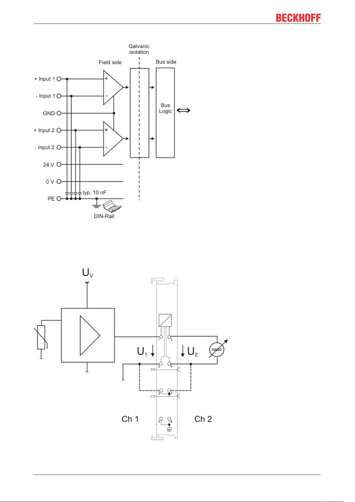
Mounting and wiring
Electrical isolation of the inputs
Fig.46: Electrical isolation of the inputs
Sample: EL3602 wiring
In figure 2, the circuit diagram with a variable voltage source (channel 2) should be regarded as equivalent to
the configuration of channel 1 with a sensor and measuring amplifier.
Fig.47: EL3702 - equivalent circuit diagram with variable voltage source
EL37x258 Version: 3.8
Page 59

Mounting and wiring
Sample: EL3742 wiring
In figure 2, the circuit diagram with a variable current source (channel 2) should be regarded as equivalent to
the configuration of channel 1 with a sensor.
Fig.48: EL3742 - equivalent circuit diagram with variable current source
EL37x2 59Version: 3.8
Page 60

Commissioning
6 Commissioning
6.1 TwinCAT Quick Start
TwinCAT is a development environment for real-time control including multi-PLC system, NC axis control,
programming and operation. The whole system is mapped through this environment and enables access to a
programming environment (including compilation) for the controller. Individual digital or analog inputs or
outputs can also be read or written directly, in order to verify their functionality, for example.
For further information please refer to http://infosys.beckhoff.com:
• EtherCAT Systemmanual:
Fieldbus Components → EtherCAT Terminals → EtherCAT System Documentation → Setup in the
TwinCAT System Manager
• TwinCAT2 → TwinCAT System Manager → I/O - Configuration
• In particular, TwinCAT driver installation:
Fieldbus components → Fieldbus Cards and Switches → FC900x – PCI Cards for Ethernet →
Installation
Devices contain the terminals for the actual configuration. All configuration data can be entered directly via
editor functions (offline) or via the “Scan” function (online):
• “offline”: The configuration can be customized by adding and positioning individual components.
These can be selected from a directory and configured.
◦ The procedure for offline mode can be found under http://infosys.beckhoff.com:
TwinCAT2 → TwinCAT System Manager → IO - Configuration → Adding an I/O Device
• “online”: The existing hardware configuration is read
◦ See also http://infosys.beckhoff.com:
Fieldbus components → Fieldbus cards and switches → FC900x – PCI Cards for Ethernet →
Installation → Searching for devices
The following relationship is envisaged from user PC to the individual control elements:
EL37x260 Version: 3.8
Page 61

Commissioning
Fig.49: Relationship between user side (commissioning) and installation
The user inserting of certain components (I/O device, terminal, box...) is the same in TwinCAT2 and
TwinCAT3. The descriptions below relate to the online procedure.
Sample configuration (actual configuration)
Based on the following sample configuration, the subsequent subsections describe the procedure for
TwinCAT2 and TwinCAT3:
• Control system (PLC) CX2040 including CX2100-0004 power supply unit
• Connected to the CX2040 on the right (E-bus):
EL1004 (4-channel digital input terminal 24VDC)
• Linked via the X001 port (RJ-45): EK1100 EtherCAT Coupler
• Connected to the EK1100 EtherCAT coupler on the right (E-bus):
EL2008 (8-channel digital output terminal 24VDC;0.5A)
• (Optional via X000: a link to an external PC for the user interface)
EL37x2 61Version: 3.8
Page 62

Commissioning
Fig.50: Control configuration with Embedded PC, input (EL1004) and output (EL2008)
Note that all combinations of a configuration are possible; for example, the EL1004 terminal could also be
connected after the coupler, or the EL2008 terminal could additionally be connected to the CX2040 on the
right, in which case the EK1100 coupler wouldn’t be necessary.
EL37x262 Version: 3.8
Page 63

Commissioning
6.1.1 TwinCAT 2
Startup
TwinCAT basically uses two user interfaces: the TwinCAT System Manager for communication with the
electromechanical components and TwinCAT PLC Control for the development and compilation of a
controller. The starting point is the TwinCAT System Manager.
After successful installation of the TwinCAT system on the PC to be used for development, the TwinCAT2
System Manager displays the following user interface after startup:
Fig.51: Initial TwinCAT2 user interface
Generally, TwinCAT can be used in local or remote mode. Once the TwinCAT system including the user
interface (standard) is installed on the respective PLC, TwinCAT can be used in local mode and thereby the
next step is “Insert Device [}65]”.
If the intention is to address the TwinCAT runtime environment installed on a PLC as development
environment remotely from another system, the target system must be made known first. In the menu under
“Actions” → “Choose Target System...”, via the symbol “ ” or the “F8” key, open the following window:
EL37x2 63Version: 3.8
Page 64

Commissioning
Fig.52: Selection of the target system
Use “Search (Ethernet)...” to enter the target system. Thus a next dialog opens to either:
• enter the known computer name after “Enter Host Name / IP:” (as shown in red)
• perform a “Broadcast Search” (if the exact computer name is not known)
• enter the known computer IP or AmsNetID.
Fig.53: Specify the PLC for access by the TwinCAT System Manager: selection of the target system
Once the target system has been entered, it is available for selection as follows (a password may have to be
entered):
After confirmation with “OK” the target system can be accessed via the System Manager.
EL37x264 Version: 3.8
Page 65

Commissioning
Adding devices
In the configuration tree of the TwinCAT2 System Manager user interface on the left, select “I/ODevices”
and then right-click to open a context menu and select “ScanDevices…”, or start the action in the menu bar
via . The TwinCAT System Manager may first have to be set to “Configmode” via or via menu
“Actions” → “Set/Reset TwinCAT to Config Mode…” (Shift + F4).
Fig.54: Select “Scan Devices...”
Confirm the warning message, which follows, and select “EtherCAT” in the dialog:
Fig.55: Automatic detection of I/O devices: selection the devices to be integrated
Confirm the message “Find new boxes”, in order to determine the terminals connected to the devices. “Free
Run” enables manipulation of input and output values in “Config mode” and should also be acknowledged.
Based on the sample configuration [}61] described at the beginning of this section, the result is as follows:
EL37x2 65Version: 3.8
Page 66

Commissioning
Fig.56: Mapping of the configuration in the TwinCAT2 System Manager
The whole process consists of two stages, which may be performed separately (first determine the devices,
then determine the connected elements such as boxes, terminals, etc.). A scan can also be initiated by
selecting “Device ...” from the context menu, which then reads the elements present in the configuration
below:
Fig.57: Reading of individual terminals connected to a device
This functionality is useful if the actual configuration is modified at short notice.
Programming and integrating the PLC
TwinCAT PLC Control is the development environment for the creation of the controller in different program
environments: TwinCAT PLC Control supports all languages described in IEC 61131-3. There are two textbased languages and three graphical languages.
• Text-based languages
◦ Instruction List (IL)
EL37x266 Version: 3.8
Page 67

◦ Structured Text (ST)
• Graphical languages
◦ Function Block Diagram (FBD)
◦ Ladder Diagram (LD)
◦ The Continuous Function Chart Editor (CFC)
◦ Sequential Function Chart (SFC)
The following section refers to Structured Text (ST).
After starting TwinCAT PLC Control, the following user interface is shown for an initial project:
Commissioning
Fig.58: TwinCAT PLC Control after startup
Sample variables and a sample program have been created and stored under the name “PLC_example.pro”:
EL37x2 67Version: 3.8
Page 68

Commissioning
Fig.59: Sample program with variables after a compile process (without variable integration)
Warning 1990 (missing “VAR_CONFIG”) after a compile process indicates that the variables defined as
external (with the ID “AT%I*” or “AT%Q*”) have not been assigned. After successful compilation, TwinCAT
PLC Control creates a “*.tpy” file in the directory in which the project was stored. This file (“*.tpy”) contains
variable assignments and is not known to the System Manager, hence the warning. Once the System
Manager has been notified, the warning no longer appears.
First, integrate the TwinCAT PLC Control project in the System Manager via the context menu of the PLC
configuration; right-click and select “Append PLC Project…”:
Fig.60: Appending the TwinCAT PLC Control project
EL37x268 Version: 3.8
Page 69

Commissioning
Select the PLC configuration “PLC_example.tpy” in the browser window that opens. The project including the
two variables identified with “AT” are then integrated in the configuration tree of the System Manager:
Fig.61: PLC project integrated in the PLC configuration of the System Manager
The two variables “bEL1004_Ch4” and “nEL2008_value” can now be assigned to certain process objects of
the I/O configuration.
Assigning variables
Open a window for selecting a suitable process object (PDO) via the context menu of a variable of the
integrated project “PLC_example” and via “Modify Link...” “Standard”:
Fig.62: Creating the links between PLC variables and process objects
In the window that opens, the process object for the variable “bEL1004_Ch4” of type BOOL can be selected
from the PLC configuration tree:
EL37x2 69Version: 3.8
Page 70

Commissioning
Fig.63: Selecting PDO of type BOOL
According to the default setting, certain PDO objects are now available for selection. In this sample the input
of channel 4 of the EL1004 terminal is selected for linking. In contrast, the checkbox “All types” must be
ticked for creating the link for the output variables, in order to allocate a set of eight separate output bits to a
byte variable. The following diagram shows the whole process:
Fig.64: Selecting several PDOs simultaneously: activate “Continuous” and “All types”
Note that the “Continuous” checkbox was also activated. This is designed to allocate the bits contained in the
byte of the variable “nEL2008_value” sequentially to all eight selected output bits of the EL2008 terminal. In
this way it is possible to subsequently address all eight outputs of the terminal in the program with a byte
corresponding to bit 0 for channel 1 to bit 7 for channel 8 of the PLC. A special symbol ( ) at the yellow or
red object of the variable indicates that a link exists. The links can also be checked by selecting a “Goto Link
Variable” from the context menu of a variable. The object opposite, in this case the PDO, is automatically
selected:
EL37x270 Version: 3.8
Page 71

Commissioning
Fig.65: Application of a “Goto Link” variable, using “MAIN.bEL1004_Ch4” as a sample
The process of assigning variables to the PDO is completed via the menu selection “Actions” → “Generate
Mappings”, key Ctrl+M or by clicking on the symbol in the menu.
This can be visualized in the configuration:
The process of creating links can also take place in the opposite direction, i.e. starting with individual PDOs
to variable. However, in this example it would then not be possible to select all output bits for the EL2008,
since the terminal only makes individual digital outputs available. If a terminal has a byte, word, integer or
similar PDO, it is possible to allocate this a set of bit-standardized variables (type “BOOL”). Here, too, a
“Goto Link Variable” from the context menu of a PDO can be executed in the other direction, so that the
respective PLC instance can then be selected.
Activation of the configuration
The allocation of PDO to PLC variables has now established the connection from the controller to the inputs
and outputs of the terminals. The configuration can now be activated. First, the configuration can be verified
via (or via “Actions” → “Check Configuration”). If no error is present, the configuration can be
activated via (or via “Actions” → “Activate Configuration…”) to transfer the System Manager settings
to the runtime system. Confirm the messages “Old configurations are overwritten!” and “Restart TwinCAT
system in Run mode” with “OK”.
A few seconds later the real-time status is displayed at the bottom right in the System Manager.
The PLC system can then be started as described below.
Starting the controller
Starting from a remote system, the PLC control has to be linked with the Embedded PC over Ethernet via
“Online” → “Choose Run-Time System…”:
EL37x2 71Version: 3.8
Page 72

Commissioning
Fig.66: Choose target system (remote)
In this sample “Runtime system 1 (port 801)” is selected and confirmed. Link the PLC with the real-time
system via menu option “Online” → “Login”, the F11 key or by clicking on the symbol .The control
program can then be loaded for execution. This results in the message “No program on the controller!
Should the new program be loaded?”, which should be acknowledged with “Yes”. The runtime environment
is ready for the program start:
EL37x272 Version: 3.8
Page 73

Commissioning
Fig.67: PLC Control logged in, ready for program startup
The PLC can now be started via “Online” → “Run”, F5 key or .
6.1.2 TwinCAT 3
Startup
TwinCAT makes the development environment areas available together with Microsoft Visual Studio: after
startup, the project folder explorer appears on the left in the general window area (cf. “TwinCAT System
Manager” of TwinCAT2) for communication with the electromechanical components.
After successful installation of the TwinCAT system on the PC to be used for development, TwinCAT3
(shell) displays the following user interface after startup:
EL37x2 73Version: 3.8
Page 74

Commissioning
Fig.68: Initial TwinCAT3 user interface
First create a new project via (or under “File”→“New”→ “Project…”). In the
following dialog make the corresponding entries as required (as shown in the diagram):
Fig.69: Create new TwinCAT project
The new project is then available in the project folder explorer:
EL37x274 Version: 3.8
Page 75

Commissioning
Fig.70: New TwinCAT3 project in the project folder explorer
Generally, TwinCAT can be used in local or remote mode. Once the TwinCAT system including the user
interface (standard) is installed on the respective PLC, TwinCAT can be used in local mode and thereby the
next step is “Insert Device [}76]”.
If the intention is to address the TwinCAT runtime environment installed on a PLC as development
environment remotely from another system, the target system must be made known first. Via the symbol in
the menu bar:
expand the pull-down menu:
and open the following window:
Fig.71: Selection dialog: Choose the target system
EL37x2 75Version: 3.8
Page 76
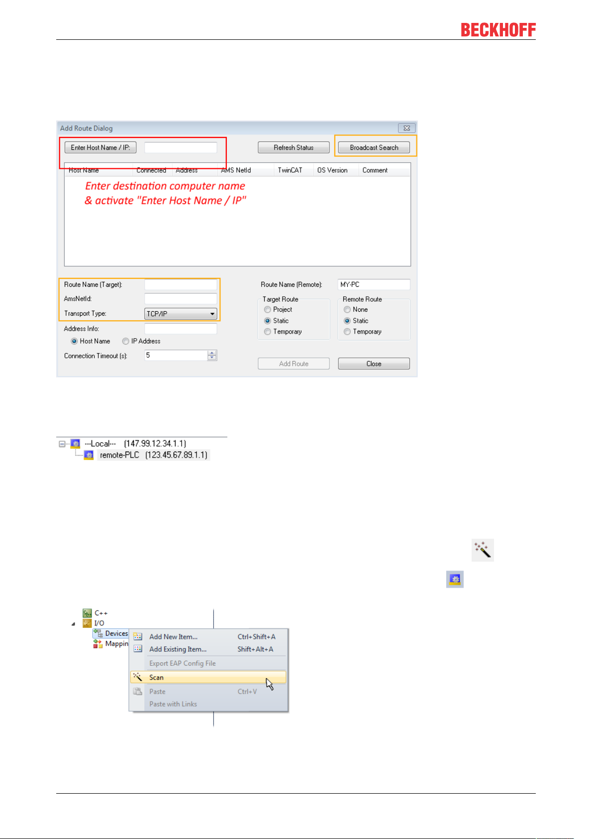
Commissioning
Use “Search (Ethernet)...” to enter the target system. Thus a next dialog opens to either:
• enter the known computer name after “Enter Host Name / IP:” (as shown in red)
• perform a “Broadcast Search” (if the exact computer name is not known)
• enter the known computer IP or AmsNetID.
Fig.72: Specify the PLC for access by the TwinCAT System Manager: selection of the target system
Once the target system has been entered, it is available for selection as follows (a password may have to be
entered):
After confirmation with “OK” the target system can be accessed via the Visual Studio shell.
Adding devices
In the project folder explorer of the Visual Studio shell user interface on the left, select “Devices” within
element “I/O”, then right-click to open a context menu and select “Scan” or start the action via in the
menu bar. The TwinCAT System Manager may first have to be set to “Config mode” via or via the
menu “TwinCAT” → “Restart TwinCAT (Config mode)”.
Fig.73: Select “Scan”
Confirm the warning message, which follows, and select “EtherCAT” in the dialog:
EL37x276 Version: 3.8
Page 77

Commissioning
Fig.74: Automatic detection of I/O devices: selection the devices to be integrated
Confirm the message “Find new boxes”, in order to determine the terminals connected to the devices. “Free
Run” enables manipulation of input and output values in “Config mode” and should also be acknowledged.
Based on the sample configuration [}61] described at the beginning of this section, the result is as follows:
Fig.75: Mapping of the configuration in VS shell of the TwinCAT3 environment
The whole process consists of two stages, which may be performed separately (first determine the devices,
then determine the connected elements such as boxes, terminals, etc.). A scan can also be initiated by
selecting “Device ...” from the context menu, which then reads the elements present in the configuration
below:
EL37x2 77Version: 3.8
Page 78

Commissioning
Fig.76: Reading of individual terminals connected to a device
This functionality is useful if the actual configuration is modified at short notice.
Programming the PLC
TwinCAT PLC Control is the development environment for the creation of the controller in different program
environments: TwinCAT PLC Control supports all languages described in IEC 61131-3. There are two textbased languages and three graphical languages.
• Text-based languages
◦ Instruction List (IL)
◦ Structured Text (ST)
• Graphical languages
◦ Function Block Diagram (FBD)
◦ Ladder Diagram (LD)
◦ The Continuous Function Chart Editor (CFC)
◦ Sequential Function Chart (SFC)
The following section refers to Structured Text (ST).
In order to create a programming environment, a PLC subproject is added to the project sample via the
context menu of “PLC” in the project folder explorer by selecting “Add New Item….”:
EL37x278 Version: 3.8
Page 79

Fig.77: Adding the programming environment in “PLC”
Commissioning
In the dialog that opens select “Standard PLC project” and enter “PLC_example” as project name, for
example, and select a corresponding directory:
Fig.78: Specifying the name and directory for the PLC programming environment
The “Main” program, which already exists by selecting “Standard PLC project”, can be opened by doubleclicking on “PLC_example_project” in “POUs”. The following user interface is shown for an initial project:
EL37x2 79Version: 3.8
Page 80

Commissioning
Fig.79: Initial “Main” program of the standard PLC project
To continue, sample variables and a sample program have now been created:
EL37x280 Version: 3.8
Page 81

Commissioning
Fig.80: Sample program with variables after a compile process (without variable integration)
The control program is now created as a project folder, followed by the compile process:
Fig.81: Start program compilation
The following variables, identified in the ST/ PLC program with “AT%”, are then available in under
“Assignments” in the project folder explorer:
Assigning variables
Via the menu of an instance - variables in the “PLC” context, use the “Modify Link…” option to open a
window for selecting a suitable process object (PDO) for linking:
EL37x2 81Version: 3.8
Page 82

Commissioning
Fig.82: Creating the links between PLC variables and process objects
In the window that opens, the process object for the variable “bEL1004_Ch4” of type BOOL can be selected
from the PLC configuration tree:
Fig.83: Selecting PDO of type BOOL
According to the default setting, certain PDO objects are now available for selection. In this sample the input
of channel 4 of the EL1004 terminal is selected for linking. In contrast, the checkbox “All types” must be
ticked for creating the link for the output variables, in order to allocate a set of eight separate output bits to a
byte variable. The following diagram shows the whole process:
EL37x282 Version: 3.8
Page 83

Commissioning
Fig.84: Selecting several PDOs simultaneously: activate “Continuous” and “All types”
Note that the “Continuous” checkbox was also activated. This is designed to allocate the bits contained in the
byte of the variable “nEL2008_value” sequentially to all eight selected output bits of the EL2008 terminal. In
this way it is possible to subsequently address all eight outputs of the terminal in the program with a byte
corresponding to bit 0 for channel 1 to bit 7 for channel 8 of the PLC. A special symbol ( ) at the yellow or
red object of the variable indicates that a link exists. The links can also be checked by selecting a “Goto Link
Variable” from the context menu of a variable. The object opposite, in this case the PDO, is automatically
selected:
Fig.85: Application of a “Goto Link” variable, using “MAIN.bEL1004_Ch4” as a sample
The process of creating links can also take place in the opposite direction, i.e. starting with individual PDOs
to variable. However, in this example it would then not be possible to select all output bits for the EL2008,
since the terminal only makes individual digital outputs available. If a terminal has a byte, word, integer or
EL37x2 83Version: 3.8
Page 84

Commissioning
similar PDO, it is possible to allocate this a set of bit-standardized variables (type “BOOL”). Here, too, a
“Goto Link Variable” from the context menu of a PDO can be executed in the other direction, so that the
respective PLC instance can then be selected.
Note on the type of variable assignment
The following type of variable assignment can only be used from TwinCAT version V3.1.4024.4 onwards and is only available for terminals with a microcontroller.
In TwinCAT it is possible to create a structure from the mapped process data of a terminal. An instance of
this structure can then be created in the PLC, so it is possible to access the process data directly from the
PLC without having to declare own variables.
The procedure for the EL3001 1-channel analog input terminal -10...+10V is shown as an example.
1. First the required process data must be selected in the “Process data” tab in TwinCAT.
2. After that, the PLC data type must be generated in the tab “PLC” via the check box.
3. The data type in the “Data Type” field can then be copied using the “Copy” button.
Fig.86: Creating a PLC data type
4. An instance of the data structure of the copied data type must then be created in the PLC.
Fig.87: Instance_of_struct
5. Then the project folder must be created. This can be done either via the key combination “CTRL +
Shift + B” or via the “Build” tab in TwinCAT.
6. The structure in the “PLC” tab of the terminal must then be linked to the created instance.
EL37x284 Version: 3.8
Page 85

Fig.88: Linking the structure
Commissioning
7. In the PLC the process data can then be read or written via the structure in the program code.
Fig.89: Reading a variable from the structure of the process data
Activation of the configuration
The allocation of PDO to PLC variables has now established the connection from the controller to the inputs
and outputs of the terminals. The configuration can now be activated with or via the menu under
“TwinCAT” in order to transfer settings of the development environment to the runtime system. Confirm the
messages “Old configurations are overwritten!” and “Restart TwinCAT system in Run mode” with “OK”. The
corresponding assignments can be seen in the project folder explorer:
A few seconds later the corresponding status of the Run mode is displayed in the form of a rotating symbol
at the bottom right of the VS shell development environment. The PLC system can then be started as
described below.
EL37x2 85Version: 3.8
Page 86

Commissioning
Starting the controller
Select the menu option “PLC” → “Login” or click on to link the PLC with the real-time system and load
the control program for execution. This results in the message No program on the controller! Should the new
program be loaded?, which should be acknowledged with “Yes”. The runtime environment is ready for
program start by click on symbol , the “F5” key or via “PLC” in the menu selecting “Start”. The started
programming environment shows the runtime values of individual variables:
Fig.90: TwinCAT development environment (VS shell): logged-in, after program startup
The two operator control elements for stopping and logout result in the required action
(accordingly also for stop “Shift + F5”, or both actions can be selected via the PLC menu).
6.2 TwinCAT Development Environment
The Software for automation TwinCAT (The Windows Control and Automation Technology) will be
distinguished into:
• TwinCAT2: System Manager (Configuration) & PLC Control (Programming)
• TwinCAT3: Enhancement of TwinCAT2 (Programming and Configuration takes place via a common
Development Environment)
Details:
• TwinCAT2:
◦ Connects I/O devices to tasks in a variable-oriented manner
◦ Connects tasks to tasks in a variable-oriented manner
◦ Supports units at the bit level
◦ Supports synchronous or asynchronous relationships
◦ Exchange of consistent data areas and process images
◦ Datalink on NT - Programs by open Microsoft Standards (OLE, OCX, ActiveX, DCOM+, etc.)
EL37x286 Version: 3.8
Page 87

◦ Integration of IEC 61131-3-Software-SPS, Software- NC and Software-CNC within Windows
NT/2000/XP/Vista, Windows 7, NT/XP Embedded, CE
◦ Interconnection to all common fieldbusses
◦ More…
Additional features:
• TwinCAT3 (eXtended Automation):
◦ Visual-Studio®-Integration
◦ Choice of the programming language
◦ Supports object orientated extension of IEC 61131-3
◦ Usage of C/C++ as programming language for real time applications
◦ Connection to MATLAB®/Simulink®
◦ Open interface for expandability
◦ Flexible run-time environment
◦ Active support of Multi-Core- und 64-Bit-Operatingsystem
◦ Automatic code generation and project creation with the TwinCAT Automation Interface
◦ More…
Commissioning
Within the following sections commissioning of the TwinCAT Development Environment on a PC System for
the control and also the basically functions of unique control elements will be explained.
Please see further information to TwinCAT2 and TwinCAT3 at http://infosys.beckhoff.com.
6.2.1 Installation of the TwinCAT real-time driver
In order to assign real-time capability to a standard Ethernet port of an IPC controller, the Beckhoff real-time
driver has to be installed on this port under Windows.
This can be done in several ways. One option is described here.
In the System Manager call up the TwinCAT overview of the local network interfaces via Options → Show
Real Time Ethernet Compatible Devices.
Fig.91: System Manager “Options” (TwinCAT2)
This have to be called up by the Menü “TwinCAT” within the TwinCAT3 environment:
Fig.92: Call up under VS Shell (TwinCAT3)
EL37x2 87Version: 3.8
Page 88

Commissioning
The following dialog appears:
Fig.93: Overview of network interfaces
Interfaces listed under “Compatible devices” can be assigned a driver via the “Install” button. A driver should
only be installed on compatible devices.
A Windows warning regarding the unsigned driver can be ignored.
Alternatively an EtherCAT-device can be inserted first of all as described in chapter Offline configuration
creation, section “Creating the EtherCAT device” [}97] in order to view the compatible ethernet ports via its
EtherCAT properties (tab “Adapter”, button “Compatible Devices…”):
Fig.94: EtherCAT device properties(TwinCAT2): click on “Compatible Devices…” of tab “Adapte””
TwinCAT 3: the properties of the EtherCAT device can be opened by double click on “Device .. (EtherCAT)”
within the Solution Explorer under “I/O”:
After the installation the driver appears activated in the Windows overview for the network interface
(Windows Start → System Properties → Network)
EL37x288 Version: 3.8
Page 89

Commissioning
Fig.95: Windows properties of the network interface
A correct setting of the driver could be:
Fig.96: Exemplary correct driver setting for the Ethernet port
Other possible settings have to be avoided:
EL37x2 89Version: 3.8
Page 90

Commissioning
Fig.97: Incorrect driver settings for the Ethernet port
EL37x290 Version: 3.8
Page 91

IP address of the port used
IP address/DHCP
In most cases an Ethernet port that is configured as an EtherCAT device will not transport general
IP packets. For this reason and in cases where an EL6601 or similar devices are used it is useful to
specify a fixed IP address for this port via the “Internet Protocol TCP/IP” driver setting and to disable
DHCP. In this way the delay associated with the DHCP client for the Ethernet port assigning itself a
default IP address in the absence of a DHCP server is avoided. A suitable address space is
192.168.x.x, for example.
Commissioning
Fig.98: TCP/IP setting for the Ethernet port
EL37x2 91Version: 3.8
Page 92

Commissioning
6.2.2 Notes regarding ESI device description
Installation of the latest ESI device description
The TwinCAT EtherCAT master/System Manager needs the device description files for the devices to be
used in order to generate the configuration in online or offline mode. The device descriptions are contained
in the so-called ESI files (EtherCAT Slave Information) in XML format. These files can be requested from the
respective manufacturer and are made available for download. An *.xml file may contain several device
descriptions.
The ESI files for Beckhoff EtherCAT devices are available on the Beckhoff website.
The ESI files should be stored in the TwinCAT installation directory.
Default settings:
• TwinCAT2: C:\TwinCAT\IO\EtherCAT
• TwinCAT3: C:\TwinCAT\3.1\Config\Io\EtherCAT
The files are read (once) when a new System Manager window is opened, if they have changed since the
last time the System Manager window was opened.
A TwinCAT installation includes the set of Beckhoff ESI files that was current at the time when the TwinCAT
build was created.
For TwinCAT2.11/TwinCAT3 and higher, the ESI directory can be updated from the System Manager, if the
programming PC is connected to the Internet; by
• TwinCAT2: Option → “Update EtherCAT Device Descriptions”
• TwinCAT3: TwinCAT → EtherCAT Devices → “Update Device Descriptions (via ETG Website)…”
The TwinCAT ESI Updater [}96] is available for this purpose.
ESI
The *.xml files are associated with *.xsd files, which describe the structure of the ESI XML files. To
update the ESI device descriptions, both file types should therefore be updated.
Device differentiation
EtherCAT devices/slaves are distinguished by four properties, which determine the full device identifier. For
example, the device identifier EL2521-0025-1018 consists of:
• family key “EL”
• name “2521”
• type “0025”
• and revision “1018”
Fig.99: Identifier structure
The order identifier consisting of name + type (here: EL2521-0010) describes the device function. The
revision indicates the technical progress and is managed by Beckhoff. In principle, a device with a higher
revision can replace a device with a lower revision, unless specified otherwise, e.g. in the documentation.
Each revision has its own ESI description. See further notes [}10].
EL37x292 Version: 3.8
Page 93

Commissioning
Online description
If the EtherCAT configuration is created online through scanning of real devices (see section Online setup)
and no ESI descriptions are available for a slave (specified by name and revision) that was found, the
System Manager asks whether the description stored in the device should be used. In any case, the System
Manager needs this information for setting up the cyclic and acyclic communication with the slave correctly.
Fig.100: OnlineDescription information window (TwinCAT2)
In TwinCAT3 a similar window appears, which also offers the Web update:
Fig.101: Information window OnlineDescription (TwinCAT3)
If possible, the Yes is to be rejected and the required ESI is to be requested from the device manufacturer.
After installation of the XML/XSD file the configuration process should be repeated.
NOTE
Changing the “usual” configuration through a scan
ü If a scan discovers a device that is not yet known to TwinCAT, distinction has to be made between two
cases. Taking the example here of the EL2521-0000 in the revision 1019
a) no ESI is present for the EL2521-0000 device at all, either for the revision 1019 or for an older revision.
The ESI must then be requested from the manufacturer (in this case Beckhoff).
b) an ESI is present for the EL2521-0000 device, but only in an older revision, e.g. 1018 or 1017.
In this case an in-house check should first be performed to determine whether the spare parts stock allows the integration of the increased revision into the configuration at all. A new/higher revision usually
also brings along new features. If these are not to be used, work can continue without reservations with
the previous revision 1018 in the configuration. This is also stated by the Beckhoff compatibility rule.
Refer in particular to the chapter “General notes on the use of Beckhoff EtherCAT IO components” and for
manual configuration to the chapter “Offline configuration creation [}97]”.
If the OnlineDescription is used regardless, the System Manager reads a copy of the device description from
the EEPROM in the EtherCAT slave. In complex slaves the size of the EEPROM may not be sufficient for the
complete ESI, in which case the ESI would be incomplete in the configurator. Therefore it’s recommended
using an offline ESI file with priority in such a case.
The System Manager creates for online recorded device descriptions a new file
“OnlineDescription0000...xml” in its ESI directory, which contains all ESI descriptions that were read online.
EL37x2 93Version: 3.8
Page 94

Commissioning
Fig.102: File OnlineDescription.xml created by the System Manager
Is a slave desired to be added manually to the configuration at a later stage, online created slaves are
indicated by a prepended symbol “>” in the selection list (see Figure Indication of an online recorded ESI of
EL2521 as an example).
Fig.103: Indication of an online recorded ESI of EL2521 as an example
If such ESI files are used and the manufacturer's files become available later, the file OnlineDescription.xml
should be deleted as follows:
• close all System Manager windows
• restart TwinCAT in Config mode
• delete “OnlineDescription0000...xml”
• restart TwinCAT System Manager
This file should not be visible after this procedure, if necessary press <F5> to update
OnlineDescription for TwinCAT3.x
In addition to the file described above “OnlineDescription0000...xml”, a so called EtherCAT cache
with new discovered devices is created by TwinCAT3.x, e.g. under Windows 7:
(Please note the language settings of the OS!)
You have to delete this file, too.
Faulty ESI file
If an ESI file is faulty and the System Manager is unable to read it, the System Manager brings up an
information window.
Fig.104: Information window for faulty ESI file (left: TwinCAT2; right: TwinCAT3)
EL37x294 Version: 3.8
Page 95

Reasons may include:
• Structure of the *.xml does not correspond to the associated *.xsd file → check your schematics
• Contents cannot be translated into a device description → contact the file manufacturer
Commissioning
EL37x2 95Version: 3.8
Page 96

Commissioning
6.2.3 TwinCAT ESI Updater
For TwinCAT2.11 and higher, the System Manager can search for current Beckhoff ESI files automatically, if
an online connection is available:
Fig.105: Using the ESI Updater (>= TwinCAT2.11)
The call up takes place under:
“Options” → “Update EtherCAT Device Descriptions”
Selection under TwinCAT3:
Fig.106: Using the ESI Updater (TwinCAT3)
The ESI Updater (TwinCAT3) is a convenient option for automatic downloading of ESI data provided by
EtherCAT manufacturers via the Internet into the TwinCAT directory (ESI = EtherCAT slave information).
TwinCAT accesses the central ESI ULR directory list stored at ETG; the entries can then be viewed in the
Updater dialog, although they cannot be changed there.
The call up takes place under:
“TwinCAT” → “EtherCAT Devices” → “Update Device Description (via ETG Website)…”.
6.2.4 Distinction between Online and Offline
The distinction between online and offline refers to the presence of the actual I/O environment (drives,
terminals, EJ-modules). If the configuration is to be prepared in advance of the system configuration as a
programming system, e.g. on a laptop, this is only possible in “Offline configuration” mode. In this case all
components have to be entered manually in the configuration, e.g. based on the electrical design.
If the designed control system is already connected to the EtherCAT system and all components are
energised and the infrastructure is ready for operation, the TwinCAT configuration can simply be generated
through “scanning” from the runtime system. This is referred to as online configuration.
In any case, during each startup the EtherCAT master checks whether the slaves it finds match the
configuration. This test can be parameterised in the extended slave settings. Refer to note “Installation of
the latest ESI-XML device description” [}92].
For preparation of a configuration:
• the real EtherCAT hardware (devices, couplers, drives) must be present and installed
• the devices/modules must be connected via EtherCAT cables or in the terminal/ module strand in the
same way as they are intended to be used later
EL37x296 Version: 3.8
Page 97

Commissioning
• the devices/modules be connected to the power supply and ready for communication
• TwinCAT must be in CONFIG mode on the target system.
The online scan process consists of:
• detecting the EtherCAT device [}102] (Ethernet port at the IPC)
• detecting the connected EtherCAT devices [}103]. This step can be carried out independent of the
preceding step
• troubleshooting [}106]
The scan with existing configuration [}107] can also be carried out for comparison.
6.2.5 OFFLINE configuration creation
Creating the EtherCAT device
Create an EtherCAT device in an empty System Manager window.
Fig.107: Append EtherCAT device (left: TwinCAT2; right: TwinCAT3)
Select type “EtherCAT” for an EtherCAT I/O application with EtherCAT slaves. For the present publisher/
subscriber service in combination with an EL6601/EL6614 terminal select “EtherCAT Automation Protocol
via EL6601”.
Fig.108: Selecting the EtherCAT connection (TwinCAT2.11, TwinCAT3)
Then assign a real Ethernet port to this virtual device in the runtime system.
Fig.109: Selecting the Ethernet port
EL37x2 97Version: 3.8
Page 98

Commissioning
This query may appear automatically when the EtherCAT device is created, or the assignment can be set/
modified later in the properties dialog; see Fig. “EtherCAT device properties (TwinCAT2)”.
Fig.110: EtherCAT device properties (TwinCAT2)
TwinCAT 3: the properties of the EtherCAT device can be opened by double click on “Device .. (EtherCAT)”
within the Solution Explorer under “I/O”:
Selecting the Ethernet port
Ethernet ports can only be selected for EtherCAT devices for which the TwinCAT real-time driver is
installed. This has to be done separately for each port. Please refer to the respective installation
page [}87].
Defining EtherCAT slaves
Further devices can be appended by right-clicking on a device in the configuration tree.
Fig.111: Appending EtherCAT devices (left: TwinCAT2; right: TwinCAT3)
The dialog for selecting a new device opens. Only devices for which ESI files are available are displayed.
Only devices are offered for selection that can be appended to the previously selected device. Therefore the
physical layer available for this port is also displayed (Fig. “Selection dialog for new EtherCAT device”, A). In
the case of cable-based Fast-Ethernet physical layer with PHY transfer, then also only cable-based devices
are available, as shown in Fig. “Selection dialog for new EtherCAT device”. If the preceding device has
several free ports (e.g. EK1122 or EK1100), the required port can be selected on the right-hand side (A).
Overview of physical layer
• “Ethernet”: cable-based 100BASE-TX: EK couplers, EP boxes, devices with RJ45/M8/M12 connector
EL37x298 Version: 3.8
Page 99

• “E-Bus”: LVDS “terminal bus”, “EJ-module”: EL/ES terminals, various modular modules
The search field facilitates finding specific devices (since TwinCAT2.11 or TwinCAT3).
Commissioning
Fig.112: Selection dialog for new EtherCAT device
By default only the name/device type is used as selection criterion. For selecting a specific revision of the
device the revision can be displayed as “Extended Information”.
Fig.113: Display of device revision
In many cases several device revisions were created for historic or functional reasons, e.g. through
technological advancement. For simplification purposes (see Fig. “Selection dialog for new EtherCAT
device”) only the last (i.e. highest) revision and therefore the latest state of production is displayed in the
selection dialog for Beckhoff devices. To show all device revisions available in the system as ESI
descriptions tick the “Show Hidden Devices” check box, see Fig. “Display of previous revisions”.
EL37x2 99Version: 3.8
Page 100

Commissioning
Fig.114: Display of previous revisions
Device selection based on revision, compatibility
The ESI description also defines the process image, the communication type between master and
slave/device and the device functions, if applicable. The physical device (firmware, if available) has
to support the communication queries/settings of the master. This is backward compatible, i.e.
newer devices (higher revision) should be supported if the EtherCAT master addresses them as an
older revision. The following compatibility rule of thumb is to be assumed for Beckhoff EtherCAT
Terminals/ Boxes/ EJ-modules:
device revision in the system >= device revision in the configuration
This also enables subsequent replacement of devices without changing the configuration (different
specifications are possible for drives).
Example
If an EL2521-0025-1018 is specified in the configuration, an EL2521-0025-1018 or higher (-1019, -1020) can
be used in practice.
Fig.115: Name/revision of the terminal
If current ESI descriptions are available in the TwinCAT system, the last revision offered in the selection
dialog matches the Beckhoff state of production. It is recommended to use the last device revision when
creating a new configuration, if current Beckhoff devices are used in the real application. Older revisions
should only be used if older devices from stock are to be used in the application.
In this case the process image of the device is shown in the configuration tree and can be parameterized as
follows: linking with the task, CoE/DC settings, plug-in definition, startup settings, ...
EL37x2100 Version: 3.8
 Loading...