

Page 1

Documentation | EN
EJ3255
5-Channel Potentiometer Measurement with Sensor Supply
2021-03-09 | Version: 1.3
Page 2

Page 3

Table of contents
Table of contents
1 Foreword ....................................................................................................................................................5
1.1 Notes on the documentation..............................................................................................................5
1.2 Safety instructions .............................................................................................................................6
1.3 Intended use......................................................................................................................................7
1.4 Signal distribution board ....................................................................................................................7
1.5 Documentation issue status ..............................................................................................................7
1.6 Guide through documentation ...........................................................................................................7
1.7 Marking of EtherCAT plug-in modules...............................................................................................8
1.7.1 Beckhoff Identification Code (BIC)................................................................................... 11
1.7.2 Certificates....................................................................................................................... 13
2 System overview .....................................................................................................................................14
3 Product overview.....................................................................................................................................15
3.1 EJ3255 - Introduction ......................................................................................................................15
3.2 EJ3255 - Technical data..................................................................................................................16
3.3 EJ3255 - Pinout ...............................................................................................................................17
3.4 EJ3255 - LEDs ................................................................................................................................18
4 Installation of EJ modules ......................................................................................................................19
4.1 Power supply for the EtherCAT plug-in modules.............................................................................19
4.2 EJxxxx - dimensions........................................................................................................................21
4.3 Installation positions and minimum distances .................................................................................22
4.3.1 Minimum distances for ensuring installability................................................................... 22
4.3.2 Installation positions ........................................................................................................ 23
4.4 Codings ...........................................................................................................................................25
4.4.1 Color coding..................................................................................................................... 25
4.4.2 Mechanical position coding.............................................................................................. 26
4.5 Installation on the signal distribution board .....................................................................................27
4.6 Extension options ............................................................................................................................29
4.6.1 Using placeholder modules for unused slots ................................................................... 29
4.6.2 Linking with EtherCAT Terminals and EtherCAT Box modules via an Ethernet/EtherCAT
connection ....................................................................................................................... 30
4.7 IPC integration.................................................................................................................................31
4.8 Disassembly of the signal distribution board ...................................................................................33
5 EtherCAT basics......................................................................................................................................34
6 Commissioning........................................................................................................................................35
6.1 Note on documentation for the EL3255...........................................................................................35
6.2 EJ3255 - Object description and parameterization..........................................................................35
6.2.1 Restore object.................................................................................................................. 36
6.2.2 Configuration data ........................................................................................................... 36
6.2.3 Profile-specific objects (0x6000-0xFFFF) ........................................................................ 37
6.2.4 Input data......................................................................................................................... 37
6.2.5 Configuration data vendor-specific .................................................................................. 38
6.2.6 Information and diagnostic data....................................................................................... 38
6.2.7 Standard objects (0x1000-0x1FFF) ................................................................................. 38
EJ3255 3Version: 1.3
Page 4

Table of contents
7 Appendix ..................................................................................................................................................46
7.1 EtherCAT AL Status Codes.............................................................................................................46
7.2 EJ3255 - Firmware compatibility .....................................................................................................46
7.3 Firmware Update EL/ES/EM/ELM/EPxxxx ......................................................................................46
7.3.1 Device description ESI file/XML....................................................................................... 47
7.3.2 Firmware explanation ...................................................................................................... 50
7.3.3 Updating controller firmware *.efw................................................................................... 51
7.3.4 FPGA firmware *.rbf......................................................................................................... 53
7.3.5 Simultaneous updating of several EtherCAT devices...................................................... 57
7.4 Restoring the delivery state .............................................................................................................58
7.5 Support and Service ........................................................................................................................59
EJ32554 Version: 1.3
Page 5

Foreword
1 Foreword
1.1 Notes on the documentation
Intended audience
This description is only intended for the use of trained specialists in control and automation engineering who
are familiar with the applicable national standards.
It is essential that the documentation and the following notes and explanations are followed when installing
and commissioning these components.
It is the duty of the technical personnel to use the documentation published at the respective time of each
installation and commissioning.
The responsible staff must ensure that the application or use of the products described satisfy all the
requirements for safety, including all the relevant laws, regulations, guidelines and standards.
Disclaimer
The documentation has been prepared with care. The products described are, however, constantly under
development.
We reserve the right to revise and change the documentation at any time and without prior announcement.
No claims for the modification of products that have already been supplied may be made on the basis of the
data, diagrams and descriptions in this documentation.
Trademarks
Beckhoff®, TwinCAT®, EtherCAT®, EtherCATG®, EtherCATG10®, EtherCATP®, SafetyoverEtherCAT®,
TwinSAFE®, XFC®, XTS® and XPlanar® are registered trademarks of and licensed by Beckhoff Automation
GmbH. Other designations used in this publication may be trademarks whose use by third parties for their
own purposes could violate the rights of the owners.
Patent Pending
The EtherCAT Technology is covered, including but not limited to the following patent applications and
patents: EP1590927, EP1789857, EP1456722, EP2137893, DE102015105702 with corresponding
applications or registrations in various other countries.
EtherCAT® is registered trademark and patented technology, licensed by Beckhoff Automation GmbH,
Germany.
Copyright
© Beckhoff Automation GmbH & Co. KG, Germany.
The reproduction, distribution and utilization of this document as well as the communication of its contents to
others without express authorization are prohibited.
Offenders will be held liable for the payment of damages. All rights reserved in the event of the grant of a
patent, utility model or design.
EJ3255 5Version: 1.3
Page 6
Foreword
1.2 Safety instructions
Safety regulations
Please note the following safety instructions and explanations!
Product-specific safety instructions can be found on following pages or in the areas mounting, wiring,
commissioning etc.
Exclusion of liability
All the components are supplied in particular hardware and software configurations appropriate for the
application. Modifications to hardware or software configurations other than those described in the
documentation are not permitted, and nullify the liability of Beckhoff Automation GmbH & Co. KG.
Personnel qualification
This description is only intended for trained specialists in control, automation and drive engineering who are
familiar with the applicable national standards.
Description of instructions
In this documentation the following instructions are used.
These instructions must be read carefully and followed without fail!
DANGER
Serious risk of injury!
Failure to follow this safety instruction directly endangers the life and health of persons.
WARNING
Risk of injury!
Failure to follow this safety instruction endangers the life and health of persons.
CAUTION
Personal injuries!
Failure to follow this safety instruction can lead to injuries to persons.
NOTE
Damage to environment/equipment or data loss
Failure to follow this instruction can lead to environmental damage, equipment damage or data loss.
Tip or pointer
This symbol indicates information that contributes to better understanding.
EJ32556 Version: 1.3
Page 7

Foreword
1.3 Intended use
WARNING
Caution - Risk of injury!
EJ components may only be used for the purposes described below!
1.4 Signal distribution board
NOTE
Signal distribution board
Make sure that the EtherCAT plug-in modules are used only on a signal distribution board that has been
developed and manufactured in accordance with the Design Guide.
1.5 Documentation issue status
Version Comment
1.3 • Update chapter Technical data
1.2 • New front page
• Update chapter EJ3255 - Pinout
• Update revision status
• Structural update
1.1 • Chapters Basics communication, TwinCAT Quick Start , TwinCAT development
environment and General Notes - EtherCAT Slave Application replaced by
references in the chapter Guide through documentation
• Chapter EJ3255 - Object description and parameterization added
• Update chapter EJ3255 - Pinout
1.0 • First publication EJ3255
1.6 Guide through documentation
NOTE
Further components of documentation
The documentations named in the following table are further compontents of the complete
documentation. These documentations are required for the use of EtherCAT plug-in modules.
EJ3255 7Version: 1.3
Page 8

Foreword
No. Title Description
[1]
[2]
[3]
[4] Documentation of the corresponding terminal
EtherCAT System Documentation
Infrastructure for EtherCAT/Ethernet
Design GuideSignal-Distribution-Board for
standard EtherCAT plug-in modules
ELxxxx
• System overview
• EtherCAT basics
• Cable redundancy
• Hot Connect
• Distributed Clocks
• Configuration of EtherCAT-Components
• Technical recommendations and notes for
design, implementation an testing
Requirements for the design of a SignalDistribution-Board for standard EtherCAT plug-in
modules
• Backplane mounting guidelines
• Module placement
• Routing guidelines
• Notes on the principle of operation and
• Descriptions for configuration and
parameterization
are transferable to the corresponding Module
EJxxxx (s. note on documentation of ELxxxx
[}35]).
1.7 Marking of EtherCAT plug-in modules
Designation
A Beckhoff EtherCAT device has a 14-digit technical designation, made up as follows (e.g.
EJ1008-0000-0017)
• Order identifier
◦ family key: EJ
◦ product designation: The first digit of product designation is used for assignment to a product
group (e.g. EJ2xxx = digital output module).
◦ Version number: The four digit version number identifies different product variants.
• Revision number:
It is incremented when changes are made to the product.
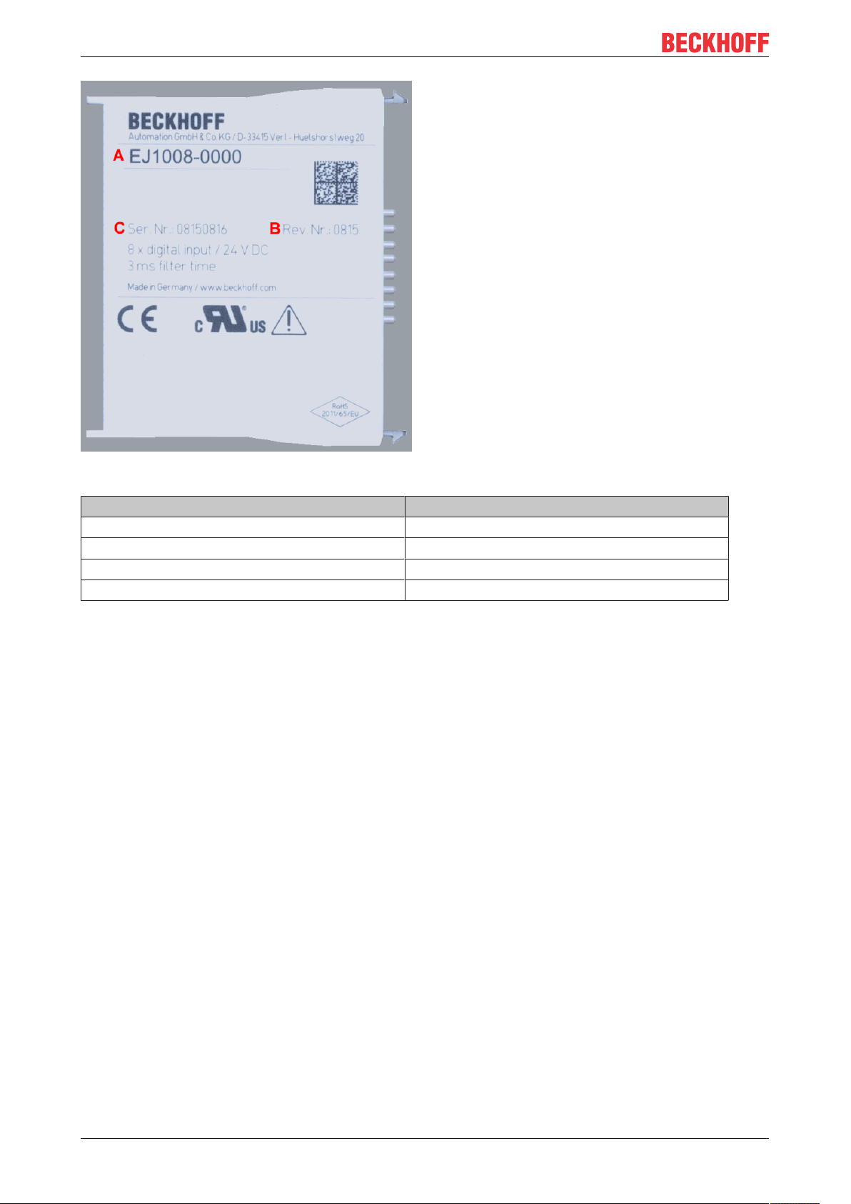
The Order identifier and the revision number are printed on the side of EtherCAT plug-in modules (s.
following illustration (A and B).
EJ32558 Version: 1.3
Page 9

Foreword
Fig.1: Order identifier (A), Revision number (B) and serial number (C) using the example of EJ1008
Product group Example
Product designation Version Revision
EtherCAT Coupler
EJ11xx
Digital input modules
EJ1xxx
Digital output modules
EJ2xxx
Analog input modules
EJ3xxx
Analog output modules
EJ4xxx
Special function modules
EJ5xxx, EJ6xxx
Motion modules
EJ7xxx
EJ1101 -0022
EJ1008
8-channel
EJ2521
1-channel
EJ3318
8-channel thermocouple
EJ4134
4-channel
EJ6224
IO-Link master
EJ7211
servomotor
(Coupler with external connectors, power supply module and
optional ID switches
-0000
(basic type)
-0224
(2 x 24V outputs)
-0000
(basic type)
-0000
(basic type)
-0090
(with TwinSAFE SC)
-9414
(with ECT, STO and TwinSAFE SC)
Notes
• The elements mentioned above result in the technical designation. EJ1008-0000-0017 is used in the
example below.
• EJ1008-0000 is the order identifier, in the case of “-0000” usually abbreviated to EJ1008.
• The revision -0017 shows the technical progress, such as the extension of features with regard to the
EtherCAT communication, and is managed by Beckhoff.
In principle, a device with a higher revision can replace a device with a lower revision, unless specified
otherwise, e.g. in the documentation.
Associated and synonymous with each revision there is usually a description (ESI, EtherCAT Slave
Information) in the form of an XML file, which is available for download from the Beckhoff web site.
• The product designation, version and revision are read as decimal numbers, even if they are
technically saved in hexadecimal.
-0016
-0017
-0016
-0017
-0019
-0016
-0029
Serial number
The serial number for EtherCAT plug-in modules is usually the 8-digit number printed on the side of the
module (see following illustration C). The serial number indicates the configuration in delivery state and
therefore refers to a whole production batch, without distinguishing the individual modules of a batch.
EJ3255 9Version: 1.3
Page 10
Foreword
Fig.2: Order identifier (A), revision number (B) and serial number (C) using the example of EJ1008
Serial number Example serial number: 08 15 08 16
KK - week of production (CW, calendar week) 08 - week of production: 08
YY - year of production 15 - year of production: 2015
FF - firmware version 08 -f irmware version: 08
HH - hardware version 16 - hardware version: 16
EJ325510 Version: 1.3
Page 11
Foreword
1.7.1 Beckhoff Identification Code (BIC)
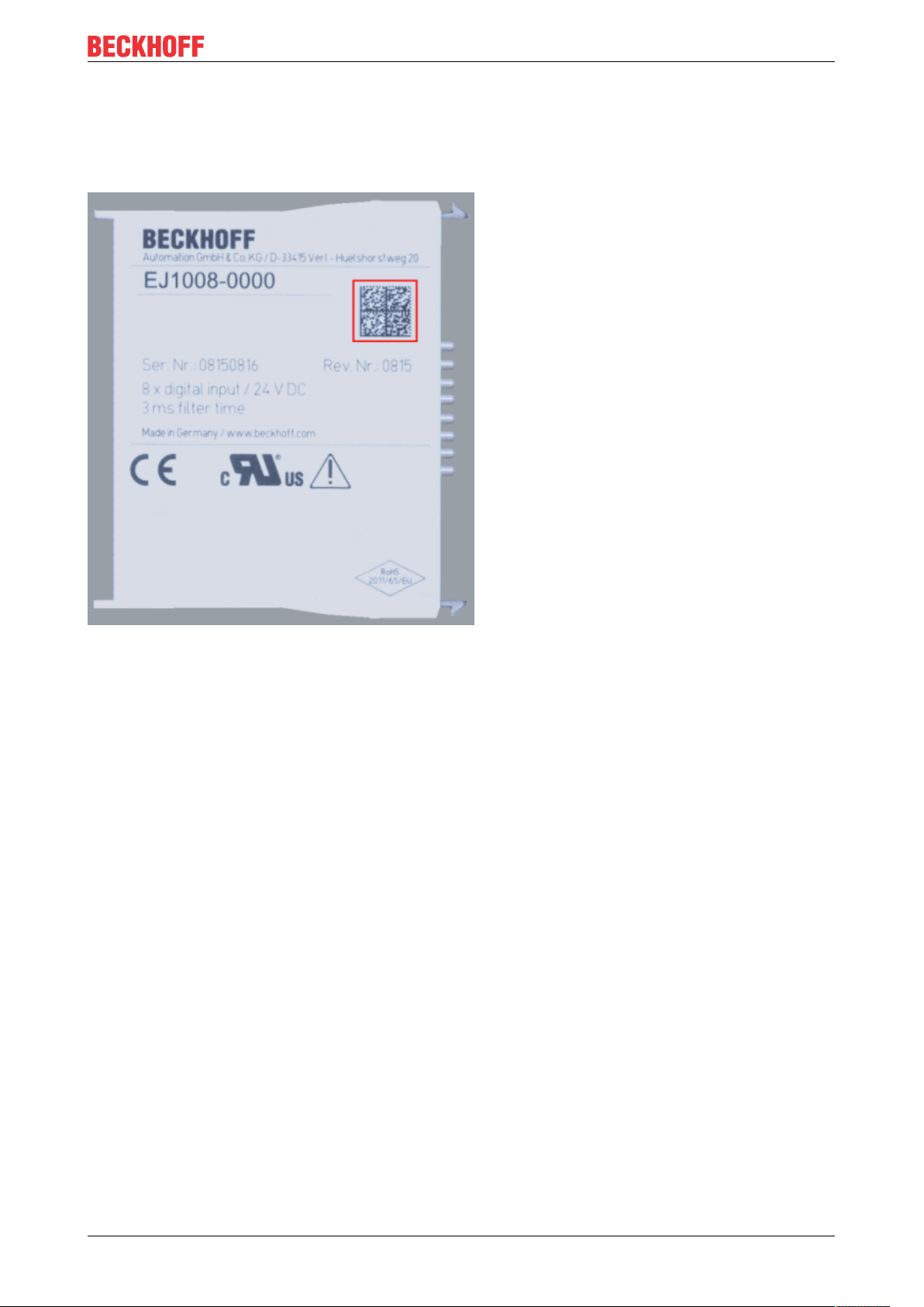
The Beckhoff Identification Code (BIC) is increasingly being applied to Beckhoff products to uniquely identify
the product. The BIC is represented as a Data Matrix Code (DMC, code scheme ECC200), the content is
based on the ANSI standard MH10.8.2-2016.
Fig.3: BIC as data matrix code (DMC, code scheme ECC200)
The BIC will be introduced step by step across all product groups.
Depending on the product, it can be found in the following places:
• on the packaging unit
• directly on the product (if space suffices)
• on the packaging unit and the product
The BIC is machine-readable and contains information that can also be used by the customer for handling
and product management.
Each piece of information can be uniquely identified using the so-called data identifier (ANSI
MH10.8.2-2016). The data identifier is followed by a character string. Both together have a maximum length
according to the table below. If the information is shorter, it shall be replaced by spaces. The data under
positions 1-4 are always available.
The following information is contained:
EJ3255 11Version: 1.3
Page 12

Foreword
Item
no.
1 Beckhoff order
2 Beckhoff Traceability
3 Article description Beckhoff article
4 Quantity Quantity in packaging
5 Batch number Optional: Year and week
6 ID/serial number Optional: Present-day
7 Variant number Optional: Product variant
...
Further types of information and data identifiers are used by Beckhoff and serve internal processes.
Structure of the BIC
Type of information
number
Number (BTN)
Explanation Data iden-
tifier
Beckhoff order number 1P 8 1P072222
Unique serial number,
see note below
description, e.g. EL1008
unit, e.g. 1, 10, etc.
of production
serial number system,
e.g. with safety products
number on the basis of
standard products
S 12 SBTNk4p562d7
1K 32 1KEL1809
Q 6 Q1
2P 14 2P4015031800
51S 12 51S678294104
30P 32 30PF971 ,
Number of digits
incl. data identifier
Example
16
2*K183
Example of composite information from items 1 - 4 and 6. The data identifiers are marked in red for better
display:
BTN
An important component of the BIC is the Beckhoff Traceability Number (BTN, item no. 2). The BTN is a
unique serial number consisting of eight characters that will replace all other serial number systems at
Beckhoff in the long term (e.g. batch designations on IO components, previous serial number range for
safety products, etc.). The BTN will also be introduced step by step, so it may happen that the BTN is not yet
coded in the BIC
Notice
This information has been carefully prepared. However, the procedure described is constantly being further
developed. We reserve the right to revise and change procedures and documentation at any time and
without prior notice. No claims for changes can be made from the information, illustrations and descriptions
in this information.
EJ325512 Version: 1.3
Page 13

1.7.2 Certificates
• The EhterCAT plug-in modules meet the requirements of the EMC and Low Voltage Directive. The CE
mark is printed on the side of the modules.
• The cRUus imprint identifies devices that meet product safety requirements according to U.S. and
Canadian regulations.
• The warning symbol is a request to read the corresponding documentation. The documentations for
EtherCAT plug-in modules can be downloaded from the Beckhoff homepage.
Foreword
Fig.4: Marking for CE and UL using EJ1008 as an example
EJ3255 13Version: 1.3
Page 14
System overview
2 System overview
Electronically, the EJxxxx EtherCAT plug-in modules are based on the EtherCAT I/O system. The EJ system
consists of the signal distribution board and EtherCAT plug-in modules. It is also possible to connect an IPC
to the EJ system.
The EJ system is suitable for mass production applications, applications with small footprint and applications
requiring a low total weight.
The machine complexity can be extended by means of the following:
• reserve slots,
• the use of placeholder modules,
• linking of EtherCAT Terminals and EtherCAT Boxes via an EtherCAT connection.
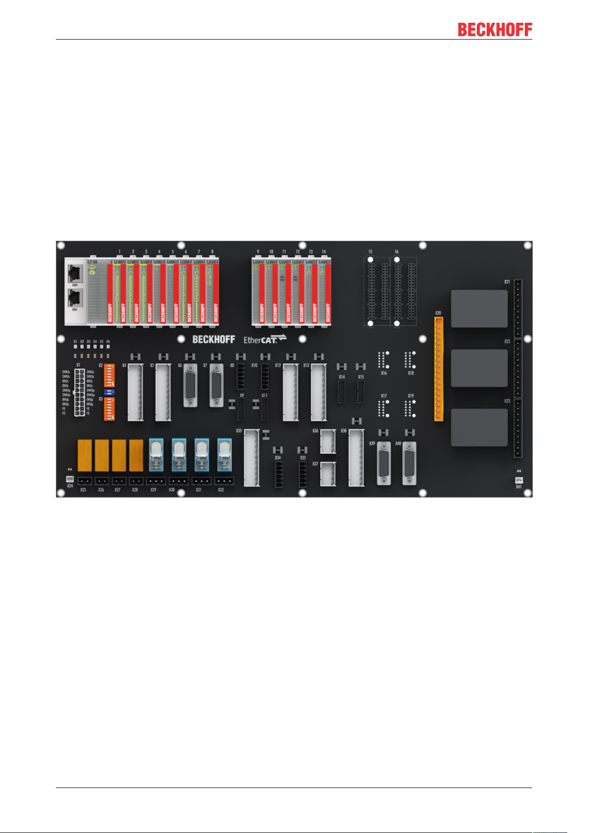
The following diagram illustrates an EJ system. The components shown are schematic, to illustrate the
functionality.
Fig.5: EJ system sample
Signal distribution board
The signal distribution board distributes the signals and the power supply to individual application-specific
plug connectors, in order to connect the controller to further machine modules. Using pre-assembled cable
harnesses avoids the need for time-consuming connection of individual wires. Coded components reduce
the unit costs and the risk of miswiring.
Beckhoff offers development of signal distribution boards as an engineering service. Customers have the
option to develop their own signal distribution board, based on the design guide.
EtherCAT plug-in modules
Similar to the EtherCAT terminal system, a module strand consists of a Bus Coupler and I/O modules.
Almost all of the EtherCAT Terminals can also be manufactured in the EJ design as EtherCAT plug-in
modules. The EJ modules are directly attached to the signal distribution board. The communication, signal
distribution and supply take place via the contact pins at the rear of the modules and the PCB tracks of the
signal distribution board. The coding pins at the rear serve as mechanical protection against incorrect
connection. Color coding on the housing facilitates distinguishing of the modules.
EJ325514 Version: 1.3
Page 15

3 Product overview
3.1 EJ3255 - Introduction
Product overview
Fig.6: EJ3255
5-channel analog input module, potentiometer measurement with Sensor supply
The EJ3255 EtherCAT plug-in module enables potentiometers to be connected directly. A stabilized power
supply in the module for the connected potentiometers and ratiometric measurement of the input voltage
offer the prerequisites for precise measuring. On account of its high sampling rate and together with
potentiometer position encoders, the compact, 5-channel EtherCAT plug-in module enables a temporally
high-resolution and cost-efficient position detection.
The EJ3255 diagnostics detect broken wire, loss of supply voltage and short-circuit for each channel.
The 5 channels are measured simultaneously (at the same time).
EJ3255 15Version: 1.3
Page 16

Product overview
3.2 EJ3255 - Technical data
Technical data EJ3255
Number of analog inputs 5
Power supply via Up contacts
Technology ratiometric potentiometer evaluation with own supply, 3-wire
connection
Distributed Clocks yes
Feed voltage potentiometer typ. 10V±10%
Internal resistance >> 100kΩ to wiper connection
Input filter limit frequency typ. -3dB at 3kHz and potentiometer 50kΩ
Sensor types Potentiometer 300Ω ..50kΩ
Output current Max. 0.3A total supply current for the potentiometers
Wiring fail indication yes
Conversion time typ. 300 ..700µs, dependent on settings,
default setting: approx.. 500µs (5 channels, filter deactivated)
Resolution 16bits representation (including sign)
Measuring error (total measuring
range)
Electrical isolation 500V (E-bus/signal voltage)
Current consumption load voltage (Up
contacts)
Current consumption via E-bus typ. 80mA
Special Features Open-circuit recognition, supply monitoring, activatable filters
Permissible ambient temperature range
during operation
Permissible ambient temperature range
during storage
Permissible relative air humidity 95%, no condensation
Operating altitude max. 2,000m
Dimensions (WxHxD) approx. 12mm x 66mm x 55mm
Weight app.30g
Mounting on signal distribution board
Pollution degree 2
Installation position
Position of the coding pins [}26]
Color coding green
Vibration/shock resistance according to EN60068-2-6/EN60068-2-27 (with corresponding
EMC immunity/emission according to EN61000-6-2/EN61000-6-4 (with corresponding
Protection class EJ module: IP20
Approval CE
< ± 0.5% (relative to full scale value)
dependent on the potentiometers, max. 125mA
simultaneous measurement of the channels
0°C .. +55°C
-25°C .. +85°C
Standard [}23]
1 and 6
signal distribution board)
signal distribution board)
EJ system: Dependent on the signal distribution board
CE approval
The CE Marking refers to the EtherCAT plug-in module mentioned above.
If the EtherCAT plug-in module is used in the production of a ready-to-use end product (PCB in conjunction with a housing), the manufacturer of the end product must check compliance of the overall
system with relevant directives and CE certification.
To operate the EtherCAT plug-in modules, they must be installed in a housing.
EJ325516 Version: 1.3
Page 17
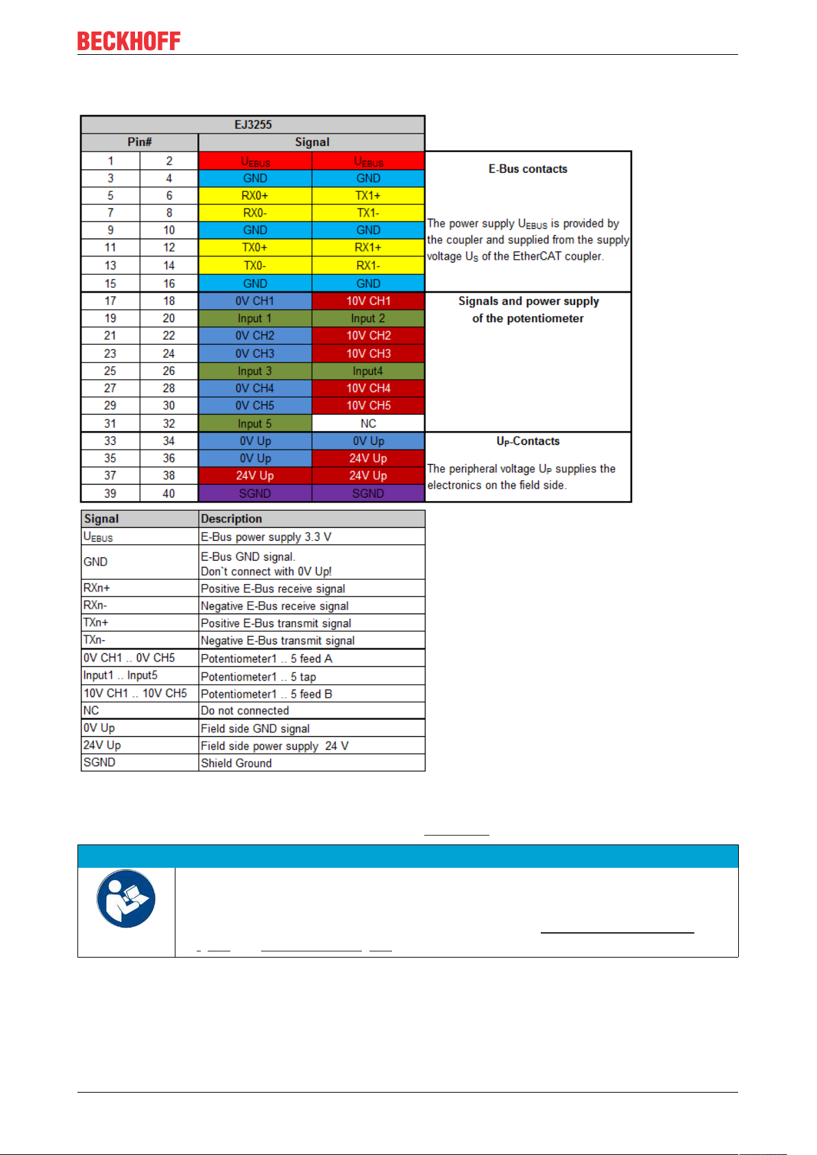
3.3 EJ3255 - Pinout
Product overview
Fig.7: EJ3255 - Pinout
The PCB footprint can be downloaded from the Beckhoff homepage.
NOTE
Damage to devices possible!
• The pins named with “NC” must not be connected.
• Before installation and commissioning read the chapters Installation of EJ modules
[}19] and Commissioning [}35]!
EJ3255 17Version: 1.3
Page 18
Product overview
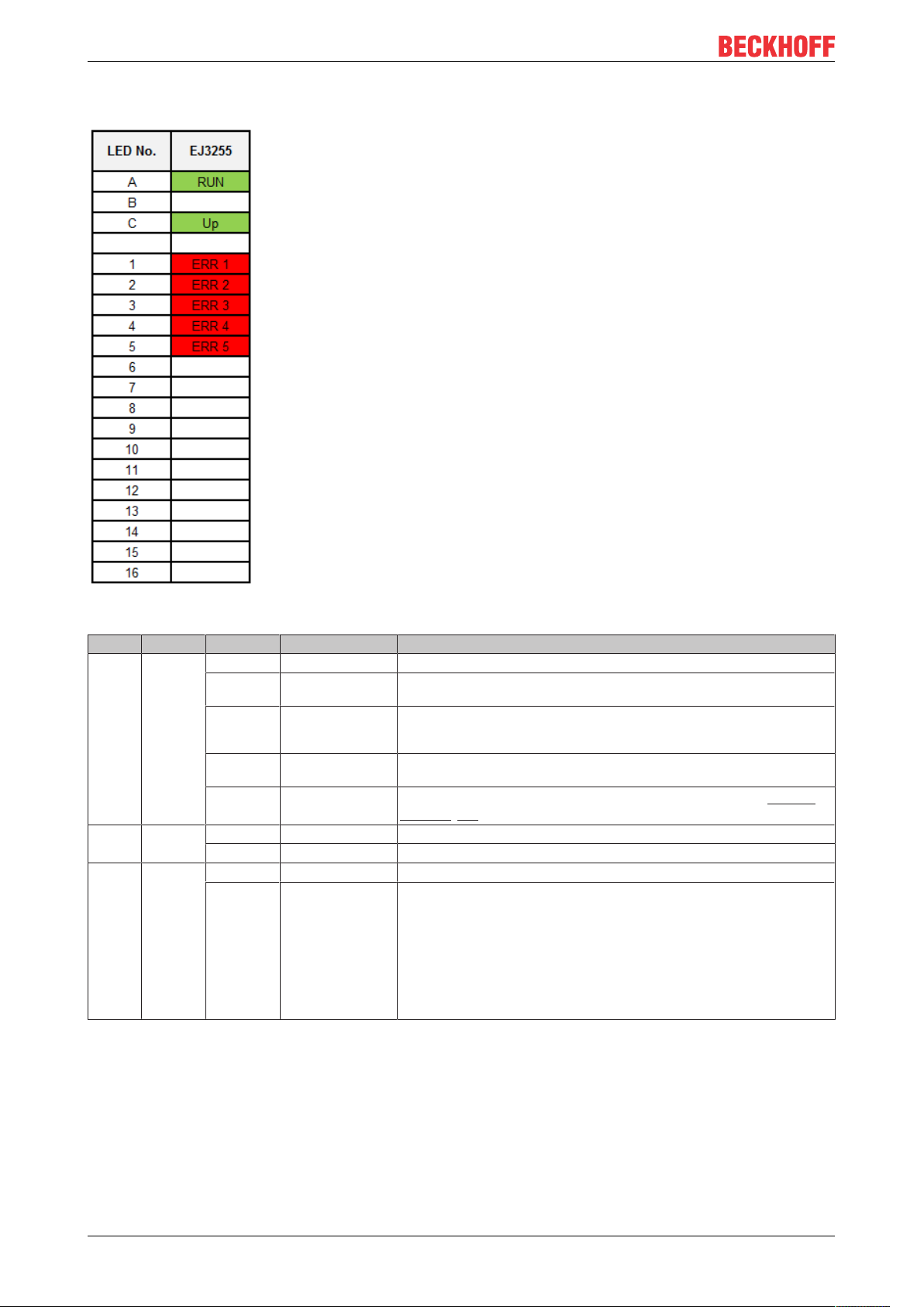
3.4 EJ3255 - LEDs
Fig.8: EJ3255 - LEDs
LED Color Display State Description
RUN green off Init State of the EtherCAT State Machine: INIT = initialization of the plug-in module
flashing Pre-Operational State of the EtherCAT State Machine: PREOP = function for mailbox commu-
single flash Safe-Operational State of the EtherCAT State Machine: SAFEOP = verification of the Sync Man-
on Operational State of the EtherCAT State Machine: OP = normal operating state; mailbox
flickering Bootstrap
Up green off - No 24VDC power supply connected
on - 24VDC power supply connected
ERR1
ERR2
ERR3
ERR4
ERR5
red off - No error
on - There is an error on the corresponding channel:
nication and different default settings set
ager channels and the distributed clocks.
Outputs remain in safe state
and process data communication is possible
State of the EtherCAT State Machine: BOOTSTRAP = function for firmware
updates [}46] of the plug-in module
• Broken wire on wiper or supply
• Potentiometer outside the specified range (300..50kΩ)
• Short-circuit
• Overload
If channels are not used they can be deactivated via the PDO selection. The
corresponding LED goes out.
EJ325518 Version: 1.3
Page 19
Installation of EJ modules
4 Installation of EJ modules
4.1 Power supply for the EtherCAT plug-in modules
WARNING
Power supply
A SELV/PELV power supply must be used to supply power for the EJ coupler and modules. Couplers and
modules have to be connected to SELV/PELV circuits exclusively.
The signal distribution board should have a power supply designed for the maximum possible current load of
the module string. Information on the current required from the E-bus supply can be found for each module
in the respective documentation in section “Technical data”, online and in the catalog. The power
requirement of the module string is displayed in the TwinCAT System Manager.
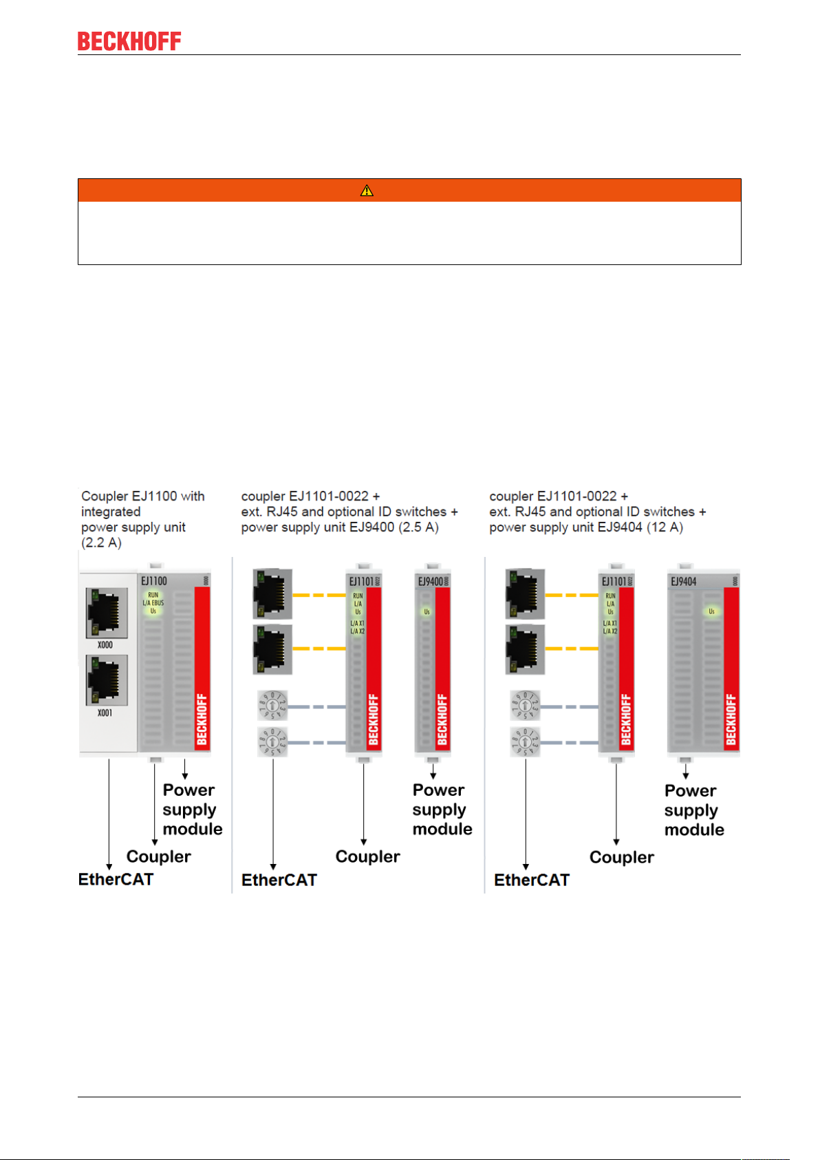
E-bus power supply with EJ1100 or EJ1101-0022 and EJ940x
The EJ1100 Bus Coupler supplies the connected EJ modules with the E-bus system voltage of 3.3V. The
Coupler can accommodate a load up to 2.2A. If a higher current is required, a combination of the coupler
EJ1101-0022 and the power supply units EJ9400 (2.5A) or EJ9404 (12A) should be used. The EJ940x
power supply units can be used as additional supply modules in the module string.
Depending on the application, the following combinations for the E-bus supply are available:
Fig.9: E-bus power supply with EJ1100 or EJ1101-0022 + EJ940x
In the EJ1101-0022 coupler, the RJ45 connectors and optional ID switches are external and can be
positioned anywhere on the signal distribution board, as required. This facilitates feeding through a housing.
The EJ940x power supply plug-in modules provide an optional reset function (see chapter Connection of the
documentation for EJ9400 and EJ9404)
EJ3255 19Version: 1.3
Page 20

Installation of EJ modules
E-bus power supply with CXxxxx and EK1110-004x
The Embedded PC supplies the attached EtherCAT terminals and the EtherCAT EJ coupler
• with a supply voltage of 24VDC (-15 %/+20%). This voltage supplies the E-bus and the bus terminal
electronics.
The CXxxxx units supply the E-bus with up to 2,000mA E-bus current. If a higher current is required
due to the attached terminals, power feed terminals or power supply plug-in modules must be used for
the E-bus supply.
• with a peripheral voltage Up of 24VDC to supply the field electronics.
The EK1110-004x EtherCAT EJ couplers relay the following parameters to the signal distribution board via
the rear connector:
• the E-bus signals,
• the E-bus voltage U
(3.3V) and
EBUS
• the peripheral voltage UP (24VDC).
Fig.10: PCB with Embedded PC, EK1110-0043 and EJxxxx, rear view EK1110-0043
EJ325520 Version: 1.3
Page 21

Installation of EJ modules
4.2 EJxxxx - dimensions
The EJ modules are compact and lightweight thanks to their design. Their volume is approx. 50% smaller
than the volume of the EL terminals. A distinction is made between four different module types, depending
on the width and the height:
Module type Dimensions (W x H x D) Sample in figure below
Coupler 44mm x 66mm x 55mm EJ1100 (ej_44_2xrj45_coupler)
Single module 12mm x 66mm x 55mm EJ1809 (ej_12_16pin_code13)
Double module 24mm x 66mm x 55mm EJ7342 (ej_24_2x16pin_code18)
Single module (long) 12mm x 152mm x 55mm EJ1957 (ej_12_2x16pin_extended_code4747)
Fig.11: EJxxxx - Dimensions
The technical drawings can be downloaded from the Beckhoff homepage. The drawings are named as
described in the drawing below.
Fig.12: Naming of the technical drawings
EJ3255 21Version: 1.3
Page 22

Installation of EJ modules
4.3 Installation positions and minimum distances
4.3.1 Minimum distances for ensuring installability
Note the dimensions shown in the following diagram for the design of the signal distribution board to ensure
safe latching and simple assembly / disassembly of the modules.
Fig.13: Mounting distances EJ module - PCB
Observing the reaching area
A minimum reaching area of 92mm is required for assembly / disassembly, in order to be able to
reach the mounting tabs with the fingers.
Adherence to the recommended minimum distances for ventilation (see section Installation position
[}23]) ensures an adequate reaching area.
The signal distribution board must have a thickness of 1.6mm and a minimum distance of 4mm from the
mounting surface, in order to ensure latching of the modules on the board.
EJ325522 Version: 1.3
Page 23

Installation of EJ modules
4.3.2 Installation positions
NOTE
Constraints regarding installation position and operating temperature range
Please refer to the technical data [}16] for the installed components to ascertain whether any restrictions
regarding the mounting position and/or the operating temperature range have been specified. During installation of modules with increased thermal dissipation, ensure adequate distance above and below the modules to other components in order to ensure adequate ventilation of the modules during operation!
The standard installation position is recommended. If a different installation position is used, check whether
additional ventilation measures are required.
Ensure that the specified conditions (see Technical data) are adhered to!
Optimum installation position (standard)
For the optimum installation position the signal distribution board is installed horizontally, and the fronts of
the EJ modules face forward (see Fig. Recommended distances for standard installation position). The
modules are ventilated from below, which enables optimum cooling of the electronics through convection.
“From below” is relative to the acceleration of gravity.
Fig.14: Recommended distances for standard installation position
Compliance with the distances shown in Fig. Recommended distances for standard installation position is
recommend. The recommended minimum distances should not be regarded as restricted areas for other
components. The customer is responsible for verifying compliance with the environmental conditions
described in the technical data. Additional cooling measures must be provided, if required.
EJ3255 23Version: 1.3
Page 24

Installation of EJ modules
Other installation positions
All other installation positions are characterized by a different spatial position of the signal distribution board,
see Fig. Other installation positions.
The minimum distances to ambient specified above also apply to these installation positions.
Fig.15: Other installation positions
EJ325524 Version: 1.3
Page 25
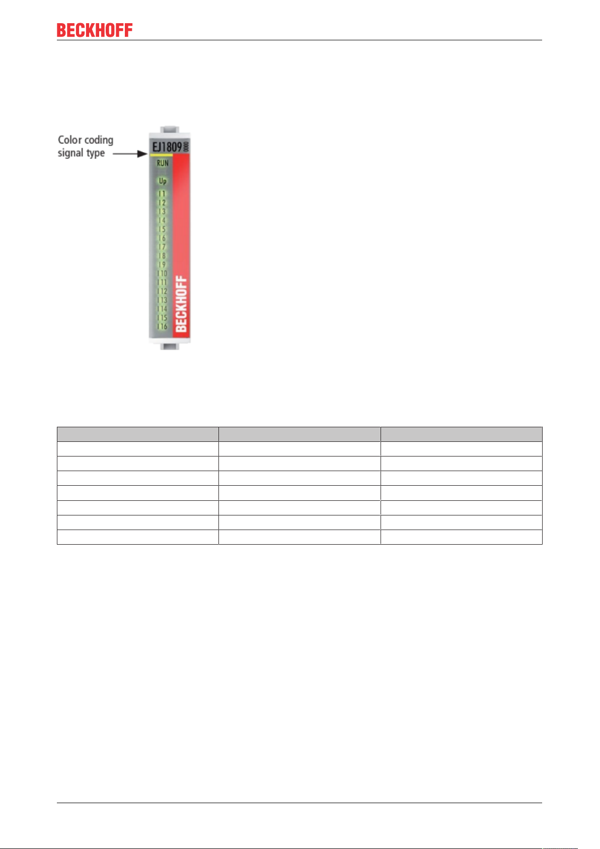
4.4 Codings
4.4.1 Color coding
Installation of EJ modules
Fig.16: EJ modules color code; sample: EJ1809
The EJ modules are color-coded for a better overview in the control cabinet (see diagram above). The color
code indicates the signal type. The following table provides an overview of the signal types with
corresponding color coding.
Signal type Modules Color
Coupler EJ11xx No color coding
Digital input EJ1xxx Yellow
Digital output EJ2xxx Red
Analog input EJ3xxx Green
Analog output EJ4xxx Blue
Motion EJ7xxx orange
System EJ9xxx grey
EJ3255 25Version: 1.3
Page 26
Installation of EJ modules
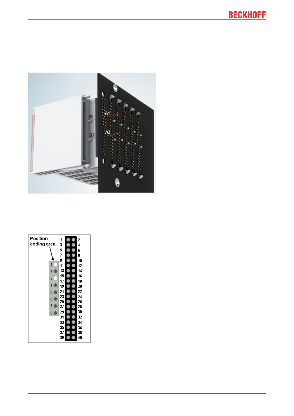
4.4.2 Mechanical position coding
The modules have two signal-specific coding pins on the underside (see Figs. B1 and B2 below). In
conjunction with the coding holes in the signal distribution board (see Figs. A1 and A2 below), the coding
pins provide an option for mechanical protection against incorrect connection. This significantly reduces the
risk of error during installation and service.
Couplers and placeholder modules have no coding pins.
Fig.17: Mechanical position coding with coding pins (B1 and B2) and coding holes (A1 and A2)
The following diagram shows the position of the position coding with position numbers on the left-hand side.
Modules with the same signal type have the same coding. For sample, all digital input modules have the
coding pins at positions one and three. There is no plug protection between modules with the same signal
type. During installation the module type should therefore be verified based on the device name.
Fig.18: Pin coding; sample: digital input modules
EJ325526 Version: 1.3
Page 27
Installation of EJ modules
4.5 Installation on the signal distribution board
EJ modules are installed on the signal distribution board. The electrical connections between coupler and EJ
modules are realized via the pin contacts and the signal distribution board.
The EJ components must be installed in a control cabinet or enclosure which must provide protection against
fire hazards, environmental conditions and mechanical impact.
WARNING
Risk of injury through electric shock and damage to the device!
Bring the module system into a safe, de-energized state before starting installation, disassembly or wiring
of the modules.
NOTE
Risk of damage to components through electrostatic discharge!
Observe the regulations for ESD protection.
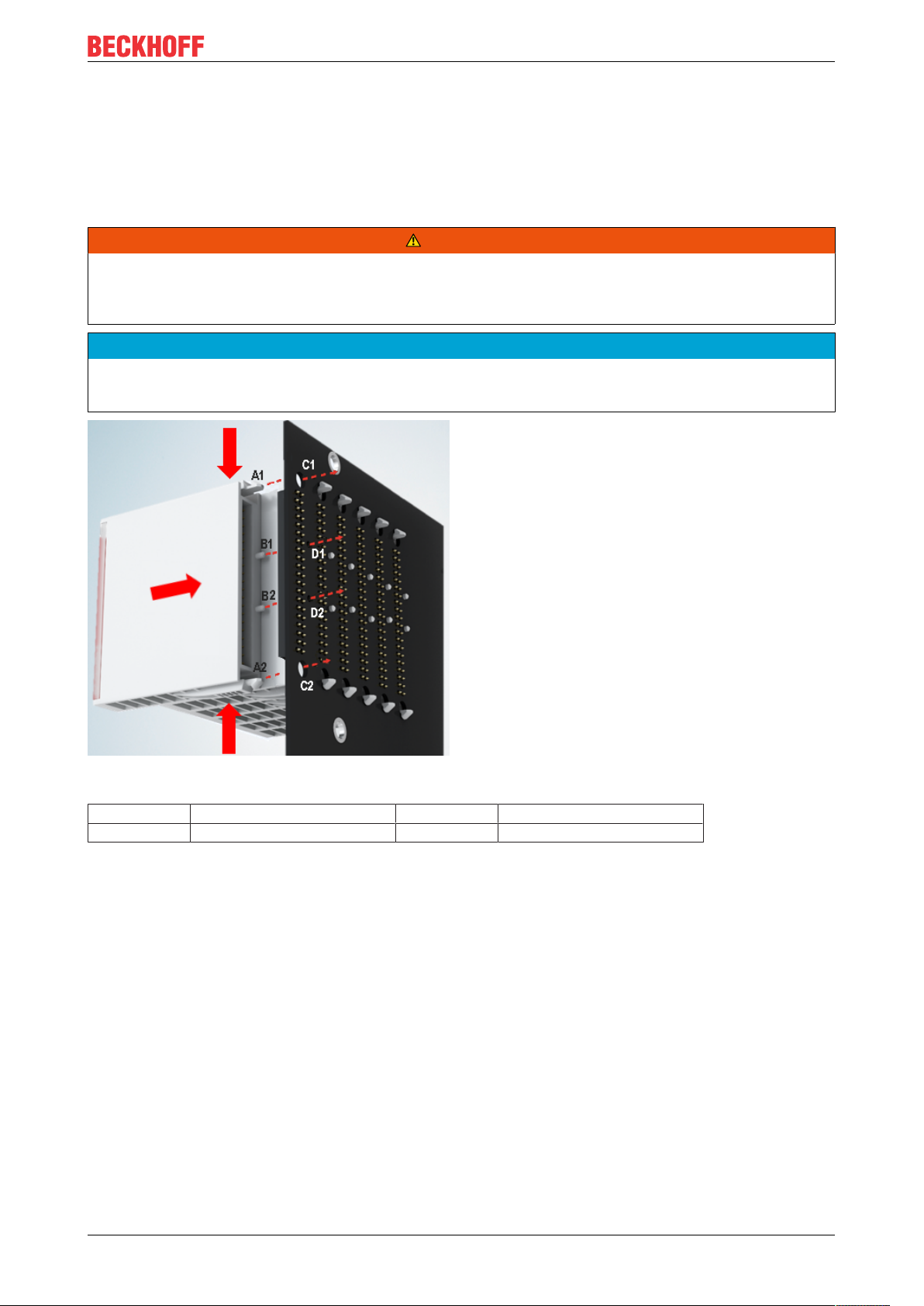
Fig.19: Installation of EJ modules
A1 / A2 Latching lugs top / bottom C1 / C2 Mounting holes
B1 / B2 Coding pins D1 / D2 Coding holes
To install the modules on the signal distribution board proceed as follows:
1. Before the installation, ensure that the signal distribution board is securely connected to the mounting
surface. Installation on an unsecured signal distribution board may result in damage to the board.
2. If necessary, check whether the positions of the coding pins (B) match the corresponding holes in the
signal distribution board (D).
3. Compare the device name on the module with the information in the installation drawing.
4. Press the upper and the lower mounting tabs simultaneously and push the module onto the board
while gently moving it up and down, until the module is latched securely.
The required contact pressure can only be established and the maximum current carrying capacity ensured if the module is latched securely.
5. Use placeholder modules (EJ9001) to fill gaps in the module strand.
EJ3255 27Version: 1.3
Page 28

Installation of EJ modules
NOTE
• During installation ensure safe latching of the modules on the signal distribution board! The consequences of inadequate contact pressure include:
ð loss of quality of the transferred signals,
ð increased power dissipation of the contacts,
ð impairment of the service life.
EJ325528 Version: 1.3
Page 29

Installation of EJ modules
4.6 Extension options
Three options are available for modifications and extensions of the EJ system.
• Replacing the placeholder modules with the function modules provided for the respective slot
• Assigning function modules specified for the respective slots for the reserve slots at the end of the
module string
• Linking with EtherCAT Terminals and EtherCAT Box modules via an Ethernet/EtherCAT connection
4.6.1 Using placeholder modules for unused slots
The EJ9001 placeholder modules are used to close temporary gaps in the module strands (see Fig. A1
below). Gaps in the module strand cause interruption in EtherCAT communication and must be equipped
with placeholder modules.
In contrast to the passive terminals of the EL series, the placeholder modules actively participate in the data
exchange. Several placeholder modules can therefore be connected in series, without impairing the data
exchange.
Unused slots at the end of the module strand can be left as reserve slots (see Fig. B1 below).
The machine complexity is extended (extended version) by allocating unused slots (see Figs. A2 below Exchanging placeholder modules and B2 - Assigning reserve slots) according to the specifications for the
signal distribution board.
Fig.20: Sample: Exchanging placeholder modules and assigning reserve slots
E-bus supply
Exchange the placeholder modules with other modules changes the current input from the E-Bus.
Ensure that adequate power supply is provided.
EJ3255 29Version: 1.3
Page 30
Installation of EJ modules
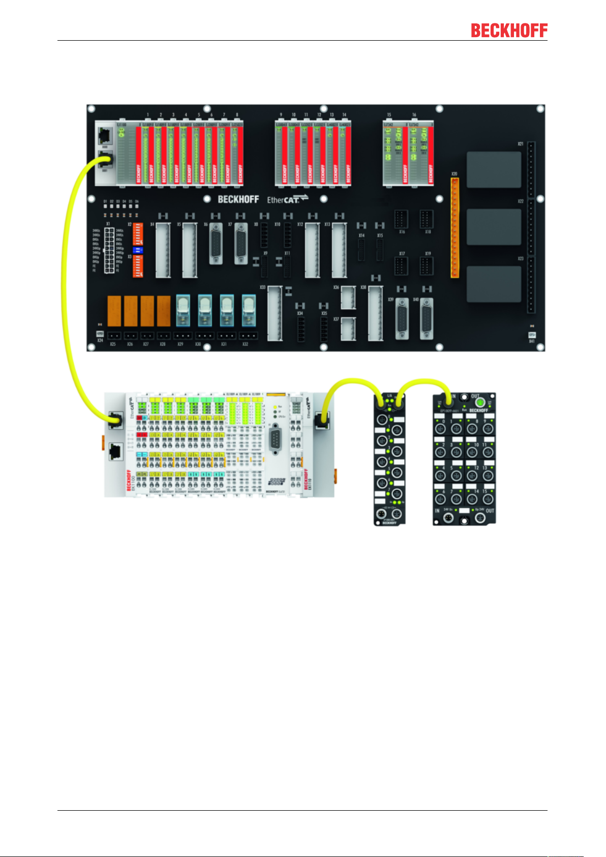
4.6.2 Linking with EtherCAT Terminals and EtherCAT Box modules via an Ethernet/EtherCAT connection
Fig.21: Example of extension via an Ethernet/EtherCAT connection
EJ325530 Version: 1.3
Page 31
Installation of EJ modules
4.7 IPC integration
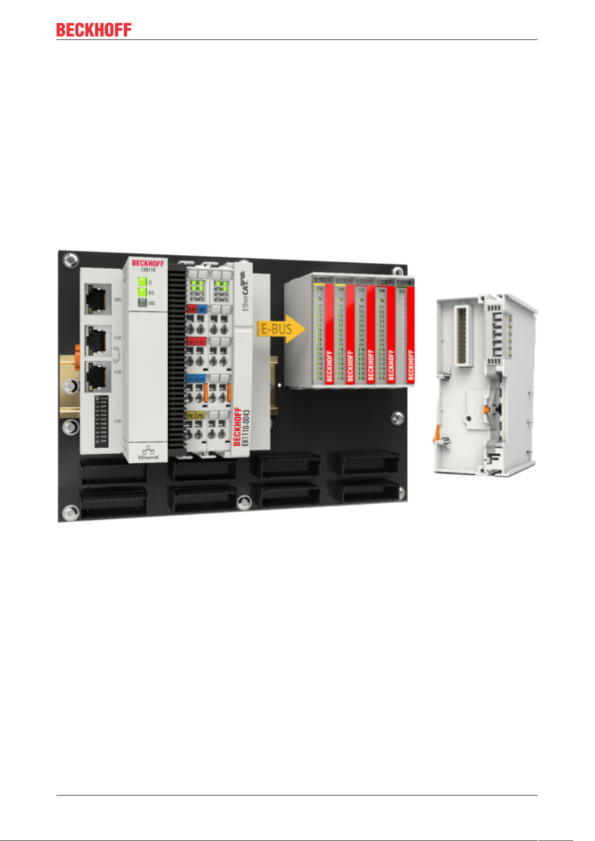
Connection of CX and EL terminals via the EK1110-004x EtherCAT EJ Coupler
The EK1110-0043 and EK1110-0044 EtherCAT EJ couplers connect the compact DIN-rail PCs of the CX
series and attached EtherCAT terminals (ELxxxx) with the EJ modules on the signal distribution board.
The EK1110-004x are supplied from the power supply unit of the Embedded PC.
The E-bus signals and the supply voltage of the field side UP are routed directly to the PCB via a plug
connector at the rear of the EtherCAT EJ couplers.
Due to the direct coupling of the Embedded PC and the EL terminals with the EJ modules on the PCB, no
EtherCAT extension (EK1110) or EtherCAT coupler (EJ1100) is required.
The Embedded PC can be expanded with EtherCAT terminals that are not yet available in the EJ system,
forexample.
Fig.22: Example PCB with Embedded PC, EK1110-0043 and EJxxxx, rear view EK1110-0043
EJ3255 31Version: 1.3
Page 32

Installation of EJ modules
Connection of C6015 / C6017 via the EJ110x-00xx EtherCAT Coupler
Thanks to their ultra-compact design and versatile mounting options, the C6015 and C6017 IPCs are ideally
suited for connection to an EJ system.
In combination with the ZS5000-0003 mounting set, it is possible to place the C6015 and C6017 IPCs
compactly on the signal distribution board.
The EJ system is optimally connected to the IPC via the corresponding EtherCAT cable (see following Fig.
[A]).
The IPC can be supplied directly via the signal distribution board using the enclosed power plug (see Fig. [B]
below).
NOTE
Positioning on the signal distribution board
The dimensions and distances for placement and other details can be found in the Design
Guide and the documentation for the individual components.
The figure below shows the connection of a C6015 IPC to an EJ system as an example. The components
shown are schematic, to illustrate the functionality.
Fig.23: Example for the connection of a C6015 IPC to an EJ system
EJ325532 Version: 1.3
Page 33

Installation of EJ modules
4.8 Disassembly of the signal distribution board
WARNING
Risk of injury through electric shock and damage to the device!
Bring the module system into a safe, de-energized state before starting installation, disassembly or wiring
of the modules.
NOTE
Risk of damage to components through electrostatic discharge!
Observe the regulations for ESD protection.
Each module is secured through latching on the distribution board, which has to be released for
disassembly.
Fig.24: Disassembly of EJ modules
To disassemble the module from the signal distribution board proceed as follows:
1. Before disassembly, ensure that the signal distribution board is securely connected to the mounting
surface. Disassembly of an unsecured signal distribution board may result in damage to the board.
2. Press the upper and lower mounting tabs simultaneously and pull the module from board while gently
moving it up and down.
EJ3255 33Version: 1.3
Page 34

EtherCAT basics
5 EtherCAT basics
Please refer to the EtherCAT System Documentation for the EtherCAT fieldbus basics.
EJ325534 Version: 1.3
Page 35

Commissioning
6 Commissioning
6.1 Note on documentation for the EL3255
Detailed documentation on the commissioning of the EJ3255 module is being prepared.
NOTE
Damage to devices or loss of data
The descriptions and notes on the commissioning of the EL3255 EtherCAT Terminal is
transferable to the EJ3255 EtherCAT plug-in modules.
Before commissioning, read the detailed description of the process data, operating modes
and parameterization in the EL3255 documentation.
6.2 EJ3255 - Object description and parameterization
EtherCAT XML Device Description
The display matches that of the CoE objects from the EtherCAT XML Device Description. We recommend downloading the latest XML file from the download area of the Beckhoff website and installing it according to installation instructions.
Parameterization via the CoE list (CAN over EtherCAT)
The EtherCAT device is parameterized via the CoE - Online tab (with a double click on the respective object) or via the Process Data tab (assignment of PDOs). A detailed description can be found
in the EtherCAT System-Documentation in chapter “EtherCAT subscriber configuration”
Please note the general CoE notes in the EtherCAT System Documentation in chapter “CoE-inter-
face” when using/manipulating the CoE parameters:
- Keep a startup list if components have to be replaced
- Differentiation between online/offline dictionary, existence of current XML description
- use "CoE reload" for resetting changes
Relevant objects
The object description refers to the Pt100 (RTD) analog input module in the two and four-channel
versions. Observe the indices with regard to the objects relevant for the respective terminal (channel dependent).
Introduction
The CoE overview contains objects for different purposes of use:
• Objects required for parameterization [}36] and profile-specific objects [}37] required during
commissioning
• Objects for indicating internal settings [}38] (may be fixed)
The following section first describes the objects required for normal operation, followed by a complete
overview of missing objects.
EJ3255 35Version: 1.3
Page 36

Commissioning
6.2.1 Restore object
Index 1011 Restore default parameters
Index
Name Meaning Data type Flags Default
(hex)
1011:0
Restore default parame-
Restore default parameters UINT8 RO 0x01 (1
ters [}58]
1011:01 SubIndex 001 If this object is set to “0x64616F6C” in the set value dia-
UINT32 RW 0x00000000 (0
log, all backup objects are reset to their delivery state.
6.2.2 Configuration data
Index 80n0 AI Settings for 0 ≤ n ≤ 4 (Ch. 1 - 5, dependent on the number of channels)
The filter characteristics are set via index 0x8000:15 [}36]
The filter frequencies are set for all channels of the module centrally via index 0x8000:15 (channel
1). All other corresponding indices 0x80n0:15 have no parameterization function! The latest
firmware version (see status table [}46]) returns an EtherCAT-compliant error message, if the filter
characteristics of other channels (index 0x80n0:06, 0x80n0:15) are set.
Index
(hex)
80n0:0 AI Settings Maximum subindex UINT8 RO 0x1C (28
80n0:01 Enable user scale Enablement of the user scaling BOOLEAN RW 0x00 (0
80n0:05 Siemens bits The S5 bits are shown in the three low-order bits (value
80n0:06 Enable filter Enable filter, which makes PLC-cycle-synchronous data
80n0:07 Enable limit 1 The status bits are set in relation to Limit 1 BOOLEAN RW 0x00 (0
80n0:08 Enable limit 2 The status bits are set in relation to Limit 2 BOOLEAN RW 0x00 (0
80n0:0A Enable user calibration Enabling of the user calibration BOOLEAN RW 0x00 (0
80n0:0B Enable vendor calibra-
80n0:0E Swap limit bits Swap limit bits BOOLEAN RW 0x01 (1
80n0:11 User scale offset User scaling offset INT16 RW 0x0000 (0
80n0:12 User scale gain This is the user scaling gain.
80n0:13 Limit 1 First limit value for setting the status bits (resolution 0.1
80n0:14 Limit 2 Second limit value for setting the status bits (resolution
Name Meaning Data type Flags Default
BOOLEAN RW 0x00 (0
0x60n0:11 [}37])
Bit 0 = 1 (“overrange” or “underrange”)
Bit 1 (not used)
Bit 2 (not used)
BOOLEAN RW 0x00 (0
exchange unnecessary
Enabling of the vendor calibration BOOLEAN RW 0x01 (1
tion
INT32 RW 0x00010000
The gain is represented in fixed-point format, with the
-16
factor 2
.
(65536
The value 1 corresponds to 65535 (0x00010000).
INT16 RW 0x0000 (0
°C)
INT16 RW 0x0000 (0
0.1 °C)
)
dec
)
dec
)
dec
)
dec
)
dec
)
dec
)
dec
)
dec
)
dec
)
dec
)
dec
)
dec
)
dec
)
dec
)
dec
EJ325536 Version: 1.3
Page 37

Commissioning
Index
Name Meaning Data type Flags Default
(hex)
80n0:15 Filter settings This object determines the digital filter settings, if it is ac-
tive via “Enable filter” (index 0x80n0:06).
UINT16 RW 0x0000 (0
dec
The possible settings are sequentially numbered.
see note "Setting the filter characteristics via Index
0x8000:15"
0: 50Hz
1: 60Hz
2: IIR1 (400Hz)
3: IIR2 (500Hz)
4: IIR3 (100Hz)
5: IIR4 (50Hz)
6: IIR5 (24Hz)
7: IIR6 (12Hz)
8: IIR7 (6.2Hz)
9: IIR8 (3.0Hz)
80n0:17 User calibration offset User calibration offset INT16 RW 0x0000 (0
dec
80n0:18 User calibration gain User gain calibration UINT16 RW 0x4000 (16384
80n0:1C Linearization Linearization for potentiometer values≥25kΩ:
0 = off (up to 10kΩ),
INT16 RW 0x0000 (0
dec
1 = 25kΩ,
2 = 50kΩ,
Index 8047 AI Device Settings
Index
(hex)
8047:0 AI Device Settings Max. Subindex UINT8 RO 0x11 (17
8047:11 Wire breakage detec-
Name Meaning Data type Flags Default
tion
0: sensor/load/supply monitoring
1: load/supply monitoring
ENUM16 RW 0x0000 (0
2: supply monitoring
3: off
)
dec
dec
)
)
)
dec
)
)
6.2.3 Profile-specific objects (0x6000-0xFFFF)
The profile-specific objects have the same meaning for all EtherCAT slaves that support the profile 5001.
6.2.4 Input data
Index 60n0 AI Inputs for 0 ≤ n ≤ 4 (Ch. 1 - 5, dependent on the number of channels)
Index
(hex)
60n0:0 AI inputs Maximum subindex UINT8 RO 0x11 (17
60n0:01 Underrange The measuring range is undershot. BOOLEAN RO 0x00 (0
60n0:02 Overrange The measuring range is overshot.
60n0:03 Limit 1 Limit value monitoring
60n0:05 Limit 2 BIT2 RO 0x00 (0
60n0:07 Error The error bit is set if the data is invalid. BOOLEAN RO 0x00 (0
60n0:0E Sync Error The Sync Error bit is only required for the Distributed
60n0:0F TxPDO State Validity of the data of the associated TxPDO (0 = valid, 1
60n0:10 TxPDO Toggle The TxPDO toggle is toggled by the slave when the data
60n0:11 Value Measured value as 32bit signed integer INT16 RO 0x0000 (0
Name Meaning Data type Flags Default
BOOLEAN RO 0x00 (0
(“open circuit” detection if “Error” [Index 0x60n0:07]) is
set
BIT2 RO 0x00 (0
0: not active
1: Value>limit value
2: Value<limit value
3: Value=limit value
Clocks mode.
It indicates whether a synchronization error occurred in
the expired cycle.
BOOLEAN RO 0x00 (0
= invalid).
BOOLEAN RO 0x00 (0
of the associated TxPDO is updated.
)
dec
)
dec
)
dec
)
dec
)
dec
)
dec
)
dec
)
dec
dec
)
EJ3255 37Version: 1.3
Page 38

Commissioning
6.2.5 Configuration data vendor-specific
Index 80nF AI Vendor data for 0 ≤ n ≤ 4 (Ch. 1 - 5)
Index
Name Meaning Data type Flags Default
(hex)
80nF:0 AI vendor data Maximum subindex UINT8 RO 0x02 (2
)
dec
80nF:01 Calibration offset Vendor calibration offset INT32 RW 0x00000000 (0
80nF:02 Calibration gain Vendor calibration gain UINT16 RW 0x4000 (16384
6.2.6 Information and diagnostic data
Index 80nE RTD Internal data for0 ≤ n ≤ 4 (Ch. 1 - 5, dependent on the number of channels)
Index
(hex)
80nE:0 AI internal data Maximum subindex UINT8 RO 0x01 (1
80nE:01 ADC raw value 1 ADC raw value 1 INT32 RO 0x00000000 (0
Index F000 Modular device profile
Index
(hex)
F000:0 Modular device profile General information for the modular device profile UINT8 RO 0x02 (2
F000:01 Module index distance Index distance of the objects of the individual channels UINT16 RO 0x0010 (16
F000:02 Maximum number of
Name Meaning Data type Flags Default
Name Meaning Data type Flags Default
Number of channels UINT16 RO 0x0001 (1
modules
)
dec
)
dec
dec
dec
)
dec
)
dec
)
dec
)
)
Index F008 Code word
Index
(hex)
F008:0 Code word currently reserved UINT32 RW 0x00000000 (0
Name Meaning Data type Flags Default
Index F010 Module list [for {n=1} (1-channel) to {n=1,..,n=4} (5-channel)]
Index
(hex)
F010:0 Module list Maximum subindex UINT8 RO 0x05 (5
F010:0n Subindex 00n AI Profiles INT32 RO 0x0000012C
Name Meaning Data type Flags Default
(300
dec
)
dec
)
6.2.7 Standard objects (0x1000-0x1FFF)
The standard objects have the same meaning for all EtherCAT slaves.
Index 1000 Device type
Index
(hex)
1000:0 Device type Device type of the EtherCAT slave: The Lo-Word con-
Name Meaning Data type Flags Default
UINT32 RO 0x012C1389
tains the CoE profile used (5001). The Hi-Word contains
(19665801
the module profile according to the modular device profile.
dec
)
dec
)
Index 1008 Device name
Index
(hex)
1008:0 Device name Device name of the EtherCAT slave STRING RO EJ3255
Name Meaning Data type Flags Default
EJ325538 Version: 1.3
Page 39

Index 1009 Hardware version
Commissioning
Index
Name Meaning Data type Flags Default
(hex)
1009:0 Hardware version Hardware version of the EtherCAT slave STRING RO 00
Index 100A Software version
Index
(hex)
100A:0 Software version Firmware version of the EtherCAT slave STRING RO 01
Name Meaning Data type Flags Default
Index 1018 Identity
Index
(hex)
1018:0 Identity Information for identifying the slave UINT8 RO 0x04 (4
1018:01 Vendor ID Vendor ID of the EtherCAT slave UINT32 RO 0x00000002 (2
1018:02 Product code Product code of the EtherCAT slave UINT32 RO ( )
1018:03 Revision Revision numberof the EtherCAT slave; the Low Word
1018:04 Serial number Serial number of the EtherCAT slave; the Low Byte (bit
Name Meaning Data type Flags Default
UINT32 RO ( )
(bit 0-15) indicates the special terminal number, the High
Word (bit 16-31) refers to the device description
UINT32 RO ( )
0-7) of the Low Word contains the year of production, the
High Byte (bit 8-15) of the Low Word contains the week
of production, the High Word (bit 16-31) is 0
)
dec
Index 10F0 Backup parameter handling
)
dec
Index
Name Meaning Data type Flags Default
(hex)
10F0:0 Backup parameter han-
dling
Information for standardized loading and saving of
backup entries
10F0:01 Checksum Checksum across all backup entries of the EtherCAT
slave
Index 1800 AI TxPDO-Par Standard Ch. 1
Index
(hex)
1800:0 AI TxPDO-Par Standard
1800:06 Exclude TxPDOs Specifies the TxPDOs (index of TxPDO mapping objects)
Name Meaning Data type Flags Default
PDO parameter TxPDO 1 UINT8 RO 0x06 (6
Ch. 1
that must not be transferred together with TxPDO 1.
Index 1801 AI TxPDO-Par Compact Ch. 1
Index
(hex)
1801:0 AI TxPDO-Par Compact
1801:06 Exclude TxPDOs Specifies the TxPDOs (index of TxPDO mapping objects)
Name Meaning Data type Flags Default
PDO parameter TxPDO 2 UINT8 RO 0x06 (6
Ch.1
that must not be transferred together with TxPDO 2.
Index 1802 AI TxPDO-Par Standard Ch. 2
UINT8 RO 0x01 (1
)
dec
UINT32 RO 0x00000000 (0
)
dec
OCTET-
RO 01 1A
STRING[2]
)
dec
OCTET-
RO 00 1A
STRING[2]
)
dec
Index
Name Meaning Data type Flags Default
(hex)
1802:0 AI TxPDO-Par Standard
PDO parameter TxPDO 3 UINT8 RO 0x06 (6
Ch.2
1802:06 Exclude TxPDOs Specifies the TxPDOs (index of TxPDO mapping objects)
that must not be transferred together with TxPDO 3.
EJ3255 39Version: 1.3
OCTET-
STRING[2]
RO 03 1A
)
dec
Page 40

Commissioning
Index 1803 AI TxPDO-Par Compact Ch. 2
Index
Name Meaning Data type Flags Default
(hex)
1803:0 AI TxPDO-Par Compact
PDO parameter TxPDO 4 UINT8 RO 0x06 (6
Ch.2
1803:06 Exclude TxPDOs Specifies the TxPDOs (index of TxPDO mapping objects)
that must not be transferred together with TxPDO 4.
Index 1804 AI TxPDO-Par Standard Ch. 3
Index
(hex)
1804:0 AI TxPDO-Par Standard
1804:06 Exclude TxPDOs Specifies the TxPDOs (index of TxPDO mapping objects)
Name Meaning Data type Flags Default
PDO parameter TxPDO 5 UINT8 RO 0x06 (6
Ch.3
that must not be transferred together with TxPDO 5.
Index 1805 AI TxPDO-Par Compact Ch. 3
Index
(hex)
1805:0 AI TxPDO-Par Compact
1805:06 Exclude TxPDOs Specifies the TxPDOs (index of TxPDO mapping objects)
Name Meaning Data type Flags Default
PDO parameter TxPDO 6 UINT8 RO 0x06 (6
Ch.3
that must not be transferred together with TxPDO 6.
Index 1806 AI TxPDO-Par Standard Ch. 4
OCTET-
STRING[2]
OCTET-
STRING[2]
OCTET-
STRING[2]
RO 02 1A
RO 05 1A
RO 04 1A
)
dec
)
dec
)
dec
Index
Name Meaning Data type Flags Default
(hex)
1806:0 AI TxPDO-Par Standard
PDO parameter TxPDO 7 UINT8 RO 0x06 (6
Ch.2
1806:06 Exclude TxPDOs Specifies the TxPDOs (index of TxPDO mapping objects)
that must not be transferred together with TxPDO 7.
Index 1807 AI TxPDO-Par Compact Ch. 4
Index
(hex)
1807:0 AI TxPDO-Par Compact
1807:06 Exclude TxPDOs Specifies the TxPDOs (index of TxPDO mapping objects)
Name Meaning Data type Flags Default
PDO parameter TxPDO 8 UINT8 RO 0x06 (6
Ch.4
that must not be transferred together with TxPDO 8.
Index 1808 AI TxPDO-Par Standard Ch. 5
Index
(hex)
1808:0 AI TxPDO-Par Standard
1808:06 Exclude TxPDOs Specifies the TxPDOs (index of TxPDO mapping objects)
Name Meaning Data type Flags Default
PDO parameter TxPDO 9 UINT8 RO 0x06 (6
Ch.5
that must not be transferred together with TxPDO 9.
Index 1809 AI TxPDO-Par Compact Ch. 5
OCTET-
STRING[2]
OCTET-
STRING[2]
OCTET-
STRING[2]
RO 07 1A
RO 06 1A
RO 09 1A
)
dec
)
dec
)
dec
Index
Name Meaning Data type Flags Default
(hex)
1809:0 AI TxPDO-Par Compact
PDO parameter TxPDO 10 UINT8 RO 0x06 (6
Ch.5
1809:06 Exclude TxPDOs Specifies the TxPDOs (index of TxPDO mapping objects)
that must not be transferred together with TxPDO 10.
OCTET-
STRING[2]
RO 08 1A
)
dec
EJ325540 Version: 1.3
Page 41

Index 1A00 AI TxPDO-Map Standard Ch. 1
Commissioning
Index
Name Meaning Data type Flags Default
(hex)
1A00:0 AI TxPDO-Map Stan-
dard Ch.1
1A00:01 SubIndex 001 1. PDO Mapping entry (object 0x6000 (AI Inputs Ch.1),
PDO Mapping TxPDO 1 UINT8 RW 0x0B (11
UINT32 RW 0x6000:01, 1
dec
entry 0x01 (Underrange))
1A00:02 SubIndex 002 2. PDO Mapping entry (object 0x6000 (AI Inputs Ch.1),
UINT32 RW 0x6000:02, 1
entry 0x02 (Overrange))
1A00:03 SubIndex 003 3. PDO Mapping entry (object 0x6000 (AI Inputs Ch.1),
UINT32 RW 0x6000:03, 2
entry 0x03 (Limit 1))
1A00:04 SubIndex 004 4. PDO Mapping entry (object 0x6000 (AI Inputs Ch.1),
UINT32 RW 0x6000:05, 2
entry 0x05 (Limit 2))
1A00:05 SubIndex 005 5. PDO Mapping entry (object 0x6000 (AI Inputs Ch.1),
UINT32 RW 0x6000:07, 1
entry 0x07 (Error))
1A00:06 SubIndex 006 6. PDO Mapping entry (1 bit align) UINT32 RW 0x0000:00, 1
1A00:07 SubIndex 007 7. PDO Mapping entry (5 bits align) UINT32 RW 0x0000:00, 5
1A00:08 SubIndex 008 8. PDO Mapping entry (object 0x6000 (AI Inputs Ch.1),
UINT32 RW 0x6000:0E, 1
entry 0x0E (Sync error))
1A00:09 SubIndex 009 9. PDO Mapping entry (object 0x6000 (AI Inputs Ch.1),
UINT32 RW 0x6000:0F, 1
entry 0x0F (TxPDO-State))
1A00:0A SubIndex 010 10. PDO Mapping entry (object 0x6000 (AI Inputs Ch.1),
UINT32 RW 0x6000:10, 1
entry 0x10 (TxPDO-Toggle))
1A00:0B SubIndex 011 11. PDO Mapping entry (object 0x6000 (AI Inputs Ch.1),
UINT32 RW 0x6000:11, 16
entry 0x11 (Value))
Index 1A01 AI TxPDO-Map Compact Ch. 1
)
Index
Name Meaning Data type Flags Default
(hex)
1A01:0 AI TxPDO-Map Com-
pact Ch.1
1A01:01 SubIndex 001 1. PDO Mapping entry (object 0x6000 (AI Inputs Ch.1),
PDO Mapping TxPDO 2 UINT8 RW 0x01 (1
UINT32 RW 0x6000:11, 1
)
dec
entry 0x11 (Value))
Index 1A02 AI TxPDO-Map Standard Ch. 2
Index
(hex)
1A02:0 AI TxPDO-Map Stan-
1A02:01 SubIndex 001 1. PDO Mapping entry (object 0x6010 (AI Inputs Ch.2),
1A02:02 SubIndex 002 2. PDO Mapping entry (object 0x6010 (AI Inputs Ch.2),
1A02:03 SubIndex 003 3. PDO Mapping entry (object 0x6010 (AI Inputs Ch.2),
1A02:04 SubIndex 004 4. PDO Mapping entry (object 0x6010 (AI Inputs Ch.2),
1A02:05 SubIndex 005 5. PDO Mapping entry (object 0x6010 (AI Inputs Ch.2),
1A02:06 SubIndex 006 6. PDO Mapping entry (1 bit align) UINT32 RW 0x0000:00, 1
1A02:07 SubIndex 007 7. PDO Mapping entry (5 bits align) UINT32 RW 0x0000:00, 5
1A02:08 SubIndex 008 8. PDO Mapping entry (object 0x6010 (AI Inputs Ch.2),
1A02:09 SubIndex 009 9. PDO Mapping entry (object 0x6010 (AI Inputs Ch.2),
1A02:0A SubIndex 010 10. PDO Mapping entry (object 0x6010 (AI Inputs Ch.2),
1A02:0B SubIndex 011 11. PDO Mapping entry (object 0x6010 (AI Inputs Ch.2),
Name Meaning Data type Flags Default
PDO Mapping TxPDO 3 UINT8 RW 0x0B (11
dard Ch.2
UINT32 RW 0x6010:01, 1
entry 0x01 (Underrange))
UINT32 RW 0x6010:02, 1
entry 0x02 (Overrange))
UINT32 RW 0x6010:03, 2
entry 0x03 (Limit 1))
UINT32 RW 0x6010:05, 2
entry 0x05 (Limit 2))
UINT32 RW 0x6010:07, 1
entry 0x07 (Error))
UINT32 RW 0x6010:0E, 1
entry 0x0E (Sync error))
UINT32 RW 0x6010:0F, 1
entry 0x0F (TxPDO-State))
UINT32 RW 0x6010:10, 1
entry 0x10 (TxPDO-Toggle))
UINT32 RW 0x6010:11, 16
entry 0x11 (Value))
dec
)
EJ3255 41Version: 1.3
Page 42

Commissioning
Index 1A03 AI TxPDO-Map Compact Ch. 2
Index
Name Meaning Data type Flags Default
(hex)
1A03:0 AI TxPDO-Map Com-
pact Ch.2
1A03:01 SubIndex 001 1. PDO Mapping entry (object 0x6010 (AI Inputs Ch.2),
PDO Mapping TxPDO 4 UINT8 RW 0x01 (1
UINT32 RW 0x6010:11, 1
)
dec
entry 0x11 (Value))
Index 1A04 AI TxPDO-Map Standard Ch. 3
Index
(hex)
1A04:0 AI TxPDO-Map Stan-
1A04:01 SubIndex 001 1. PDO Mapping entry (object 0x6020 (AI Inputs Ch.3),
1A04:02 SubIndex 002 2. PDO Mapping entry (object 0x6020 (AI Inputs Ch.3),
1A04:03 SubIndex 003 3. PDO Mapping entry (object 0x6020 (AI Inputs Ch.3),
1A04:04 SubIndex 004 4. PDO Mapping entry (object 0x6020 (AI Inputs Ch.3),
1A04:05 SubIndex 005 5. PDO Mapping entry (object 0x6020 (AI Inputs Ch.3),
1A04:06 SubIndex 006 6. PDO Mapping entry (1 bit align) UINT32 RW 0x0000:00, 1
1A04:07 SubIndex 007 7. PDO Mapping entry (5 bits align) UINT32 RW 0x0000:00, 5
1A04:08 SubIndex 008 8. PDO Mapping entry (object 0x6020 (AI Inputs Ch.3),
1A04:09 SubIndex 009 9. PDO Mapping entry (object 0x6020 (AI Inputs Ch.3),
1A04:0A SubIndex 010 10. PDO Mapping entry (object 0x6020 (AI Inputs Ch.3),
1A04:0B SubIndex 011 11. PDO Mapping entry (object 0x6020 (AI Inputs Ch.3),
Name Meaning Data type Flags Default
PDO Mapping TxPDO 5 UINT8 RW 0x0B (11
dard Ch.3
UINT32 RW 0x6020:01, 1
entry 0x01 (Underrange))
UINT32 RW 0x6020:02, 1
entry 0x02 (Overrange))
UINT32 RW 0x6020:03, 2
entry 0x03 (Limit 1))
UINT32 RW 0x6020:05, 2
entry 0x05 (Limit 2))
UINT32 RW 0x6020:07, 1
entry 0x07 (Error))
UINT32 RW 0x6020:0E, 1
entry 0x0E (Sync error))
UINT32 RW 0x6020:0F, 1
entry 0x0F (TxPDO-State))
UINT32 RW 0x6020:10, 1
entry 0x10 (TxPDO-Toggle))
UINT32 RW 0x6020:11, 16
entry 0x11 (Value))
dec
)
Index 1A05 AI TxPDO-Map Compact Ch. 3
Index
(hex)
1A05:0 AI TxPDO-Map Com-
1A05:01 SubIndex 001 1. PDO Mapping entry (object 0x6020 (AI Inputs Ch.3),
Name Meaning Data type Flags Default
PDO Mapping TxPDO 6 UINT8 RW 0x01 (1
pact Ch.3
entry 0x11 (Value))
)
dec
UINT32 RW 0x6020:11, 1
EJ325542 Version: 1.3
Page 43

Index 1A06 AI TxPDO-Map Standard Ch. 4
Commissioning
Index
Name Meaning Data type Flags Default
(hex)
1A06:0 AI TxPDO-Map Stan-
dard Ch.4
1A06:01 SubIndex 001 1. PDO Mapping entry (object 0x6030 (AI Inputs Ch.4),
PDO Mapping TxPDO 7 UINT8 RW 0x0B (11
UINT32 RW 0x6030:01, 1
dec
entry 0x01 (Underrange))
1A06:02 SubIndex 002 2. PDO Mapping entry (object 0x6030 (AI Inputs Ch.4),
UINT32 RW 0x6030:02, 1
entry 0x02 (Overrange))
1A06:03 SubIndex 003 3. PDO Mapping entry (object 0x6030 (AI Inputs Ch.4),
UINT32 RW 0x6030:03, 2
entry 0x03 (Limit 1))
1A06:04 SubIndex 004 4. PDO Mapping entry (object 0x6030 (AI Inputs Ch.4),
UINT32 RW 0x6030:05, 2
entry 0x05 (Limit 2))
1A06:05 SubIndex 005 5. PDO Mapping entry (object 0x6030 (AI Inputs Ch.4),
UINT32 RW 0x6030:07, 1
entry 0x07 (Error))
1A06:06 SubIndex 006 6. PDO Mapping entry (1 bit align) UINT32 RW 0x0000:00, 1
1A06:07 SubIndex 007 7. PDO Mapping entry (5 bits align) UINT32 RW 0x0000:00, 5
1A06:08 SubIndex 008 8. PDO Mapping entry (object 0x6030 (AI Inputs Ch.4),
UINT32 RW 0x6030:0E, 1
entry 0x0E (Sync error))
1A06:09 SubIndex 009 9. PDO Mapping entry (object 0x6030 (AI Inputs Ch.4),
UINT32 RW 0x6030:0F, 1
entry 0x0F (TxPDO-State))
1A06:0A SubIndex 010 10. PDO Mapping entry (object 0x6030 (AI Inputs Ch.4),
UINT32 RW 0x6030:10, 1
entry 0x10 (TxPDO-Toggle))
1A06:0B SubIndex 011 11. PDO Mapping entry (object 0x6030 (AI Inputs Ch.4),
UINT32 RW 0x6030:11, 16
entry 0x11 (Value))
Index 1A07 AI TxPDO-Map Compact Ch. 4
)
Index
Name Meaning Data type Flags Default
(hex)
1A07:0 AI TxPDO-Map Com-
pact Ch.4
1A07:01 SubIndex 001 1. PDO Mapping entry (object 0x6030 (AI Inputs Ch.4),
PDO Mapping TxPDO 8 UINT8 RW 0x01 (1
UINT32 RW 0x6030:11, 1
)
dec
entry 0x11 (Value))
Index 1A08 AI TxPDO-Map Standard Ch. 5
Index
(hex)
1A08:0 AI TxPDO-Map Stan-
1A08:01 SubIndex 001 1. PDO Mapping entry (object 0x6040 (AI Inputs Ch.5),
1A08:02 SubIndex 002 2. PDO Mapping entry (object 0x6040 (AI Inputs Ch.5),
1A08:03 SubIndex 003 3. PDO Mapping entry (object 0x6040 (AI Inputs Ch.5),
1A08:04 SubIndex 004 4. PDO Mapping entry (object 0x6040 (AI Inputs Ch.5),
1A08:05 SubIndex 005 5. PDO Mapping entry (object 0x6040 (AI Inputs Ch.5),
1A08:06 SubIndex 006 6. PDO Mapping entry (1 bit align) UINT32 RW 0x0000:00, 1
1A08:07 SubIndex 007 7. PDO Mapping entry (5 bits align) UINT32 RW 0x0000:00, 5
1A08:08 SubIndex 008 8. PDO Mapping entry (object 0x6040 (AI Inputs Ch.5),
1A08:09 SubIndex 009 9. PDO Mapping entry (object 0x6040 (AI Inputs Ch.5),
1A08:0A SubIndex 010 10. PDO Mapping entry (object 0x6040 (AI Inputs Ch.5),
1A08:0B SubIndex 011 11. PDO Mapping entry (object 0x6040 (AI Inputs Ch.5),
Name Meaning Data type Flags Default
PDO Mapping TxPDO 9 UINT8 RW 0x0B (11
dard Ch.5
UINT32 RW 0x6040:01, 1
entry 0x01 (Underrange))
UINT32 RW 0x6040:02, 1
entry 0x02 (Overrange))
UINT32 RW 0x6040:03, 2
entry 0x03 (Limit 1))
UINT32 RW 0x6040:05, 2
entry 0x05 (Limit 2))
UINT32 RW 0x6040:07, 1
entry 0x07 (Error))
UINT32 RW 0x6040:0E, 1
entry 0x0E (Sync error))
UINT32 RW 0x6040:0F, 1
entry 0x0F (TxPDO-State))
UINT32 RW 0x6040:10, 1
entry 0x10 (TxPDO Toggle))
UINT32 RW 0x6040:11, 16
entry 0x11 (Value))
dec
)
EJ3255 43Version: 1.3
Page 44

Commissioning
Index 1A09 AI TxPDO-Map Compact Ch. 5
Index
Name Meaning Data type Flags Default
(hex)
1A09:0 AI TxPDO-Map Com-
PDO Mapping TxPDO 10 UINT8 RW 0x01 (1
pact Ch.5
1A09:01 SubIndex 001 1. PDO Mapping entry (object 0x6040 (AI Inputs Ch.5),
UINT32 RW 0x6040:11, 1
entry 0x11 (Value))
Index 1C00 Sync manager type
Index
(hex)
1C00:0 Sync manager type Using the Sync Managers UINT8 RO 0x04 (4
1C00:01 SubIndex 001 Sync-Manager Type Channel 1: Mailbox Write UINT8 RO 0x01 (1
1C00:02 SubIndex 002 Sync-Manager Type Channel 2: Mailbox Read UINT8 RO 0x02 (2
1C00:03 SubIndex 003 Sync-Manager Type Channel 3: Process Data Write
1C00:04 SubIndex 004 Sync-Manager Type Channel 4: Process Data Read (In-
Name Meaning Data type Flags Default
UINT8 RO 0x03 (3
(Outputs)
UINT8 RO 0x04 (4
puts)
Index 1C12 RxPDO assign
Index
(hex)
1C12:0 RxPDO assign PDO Assign Outputs UINT8 RW 0x00 (0
Name Meaning Data type Flags Default
Index 1C13 TxPDO assign
)
dec
)
dec
)
dec
)
dec
)
dec
)
dec
)
dec
Index
Name Meaning Data type Flags Default
(hex)
1C13:0 TxPDO assign PDO Assign Inputs UINT8 RW 0x05 (5
1C13:01 Subindex 001 1. allocated TxPDO (contains the index of the associated
UINT16 RW 0x1A00 (6656
TxPDO mapping object)
1C13:02 Subindex 002 2. allocated TxPDO (contains the index of the associated
UINT16 RW 0x1A02 (6658
TxPDO mapping object)
1C13:03 Subindex 003 3. allocated TxPDO (contains the index of the associated
UINT16 RW 0x1A04 (6660
TxPDO mapping object)
1C13:04 Subindex 004 4. allocated TxPDO (contains the index of the associated
UINT16 RW 0x1A06 (6662
TxPDO mapping object)
1C13:05 Subindex 005 5. allocated TxPDO (contains the index of the associated
UINT16 RW 0x1A08 (6664
TxPDO mapping object)
)
dec
)
dec
)
dec
)
dec
)
dec
)
dec
EJ325544 Version: 1.3
Page 45

Index 1C33 SM input parameter
Commissioning
Index
Name Meaning Data type Flags Default
(hex)
1C33:0 SM input parameter Synchronization parameters for the inputs UINT8 RO 0x20 (32
1C33:01 Sync mode Current synchronization mode:
UINT16 RW 0x0001 (1
dec
dec
• 0: Free Run
• 1: Synchron with SM 3 Event (no outputs
available)
• 2: DC - Synchron with SYNC0 Event
• 3: DC - Synchron with SYNC1 Event
• 34: Synchron with SM 2 Event (outputs available)
1C33:02 Cycle time Cycle time (in ns):
• Free Run: Cycle time of the local timer
UINT32 RW 0x00030D40
(200000
)
dec
• Synchron with SM 2 Event: Master cycle time
• DC mode: SYNC0/SYNC1 Cycle Time
1C33:03 Shift time Time between SYNC0 event and reading of the inputs (in
ns, DC mode only)
1C33:04 Sync modes supported Supported synchronization modes:
UINT32 RW 0x0002E630
(19000
)
dec
UINT16 RO 0x400B (16359
• Bit 0: free run is supported
• Bit 1: Synchron with SM 2 Event is supported
(outputs available)
• Bit 1: Synchron with SM 3 Event is supported (no
outputs available)
• Bit 2-3 = 01: DC mode is supported
• Bit 4-5 = 01: Input Shift through local event
(outputs available)
• Bit 4-5 = 10: Input Shift with SYNC1 Event (no
outputs available)
• Bit 14 = 1: dynamic times (measurement through
writing of 0x1C33:08)
1C33:05 Minimum cycle time Minimum cycle time (in ns) UINT32 RO 0x00030D40
1C33:06 Calc and copy time Time between reading of the inputs and availability of the
inputs for the master (in ns, DC mode only)
1C33:07 Minimum delay time Minimum time between Sync-1 Event and reading of the
(200000
UINT32 RO 0x00002710
(10000
UINT32 RO 0x00000000 (0
)
dec
)
dec
inputs (in ns, DC mode only)
1C33:08 Command • 0: Measurement of the local cycle time is stopped
UINT16 RW 0x0000 (0
dec
• 1: Measurement of the local cycle time is started
The entries 0x1C33:03, 0x1C33:06, 0x1C33:09 are updated with the maximum measured values.
For a subsequent measurement the measured values
are reset
1C33:09 Maximum Delay time Time between SYNC1 event and reading of the inputs (in
UINT32 RO 0x00000000 (0
ns, DC mode only)
1C33:0B SM event missed
counter
1C33:0C Cycle exceeded counter Number of occasions the cycle time was exceeded in
Number of missed SM events in OPERATIONAL (DC
mode only)
OPERATIONAL (cycle was not completed in time or the
UINT16 RO 0x0000 (0
UINT16 RO 0x0000 (0
dec
dec
next cycle began too early)
1C33:0D Shift too short counter Number of occasions that the interval between SYNC0
and SYNC1 event was too short (DC mode only)
1C33:20 Sync error The synchronization was not correct in the last cycle
(outputs were output too late; DC mode only)
UINT16 RO 0x0000 (0
BOOLEAN RO 0x00 (0
dec
dec
)
)
)
)
dec
)
dec
)
)
dec
)
)
)
EJ3255 45Version: 1.3
Page 46

Appendix
7 Appendix
7.1 EtherCAT AL Status Codes
For detailed information please refer to the EtherCAT system description.
7.2 EJ3255 - Firmware compatibility
Beckhoff EtherCAT devices are delivered with the latest available firmware version. Compatibility of firmware
and hardware is mandatory; not every combination ensures compatibility. The overview below shows the
hardware versions on which a firmware can be operated.
Note
• It is recommended to use the newest possible firmware for the respective hardware
• Beckhoff is not under any obligation to provide customers with free firmware updates for delivered
products.
NOTE
Risk of damage to the device!
Pay attention to the instructions for firmware updates on the separate page [}46].
If a device is placed in BOOTSTRAP mode for a firmware update, it does not check when downloading
whether the new firmware is suitable.
This can result in damage to the device! Therefore, always make sure that the firmware is suitable for the
hardware version!
EJ3255
Hardware (HW) Firmware (FW) Revision no. Release date
00 - 02* 10* EJ3255-0000-0023 2019/03
*) This is the current compatible firmware/hardware version at the time of the preparing this documentation.
Check on the Beckhoff website whether more up-to-date documentation is available.
7.3 Firmware Update EL/ES/EM/ELM/EPxxxx
This section describes the device update for Beckhoff EtherCAT slaves from the EL/ES, ELM, EM, EK and
EP series. A firmware update should only be carried out after consultation with Beckhoff support.
NOTE
Only use TwinCAT 3 software!
A firmware update of Beckhoff IO devices must only be performed with a TwinCAT 3 installation. It is recommended to build as up-to-date as possible, available for free download on the Beckhoff website https://
www.beckhoff.com/en-us/.
To update the firmware, TwinCAT can be operated in the so-called FreeRun mode, a paid license is not required.
The device to be updated can usually remain in the installation location, but TwinCAT has to be operated in
the FreeRun. Please make sure that EtherCAT communication is trouble-free (no LostFrames etc.).
Other EtherCAT master software, such as the EtherCAT Configurator, should not be used, as they may not
support the complexities of updating firmware, EEPROM and other device components.
Storage locations
An EtherCAT slave stores operating data in up to three locations:
EJ325546 Version: 1.3
Page 47

Appendix
• Depending on functionality and performance EtherCAT slaves have one or several local controllers for
processing I/O data. The corresponding program is the so-called firmware in *.efw format.
• In some EtherCAT slaves the EtherCAT communication may also be integrated in these controllers. In
this case the controller is usually a so-called FPGA chip with *.rbf firmware.
• In addition, each EtherCAT slave has a memory chip, a so-called ESI-EEPROM, for storing its own
device description (ESI: EtherCAT Slave Information). On power-up this description is loaded and the
EtherCAT communication is set up accordingly. The device description is available from the download
area of the Beckhoff website at (https://www.beckhoff.com). All ESI files are accessible there as zip
files.
Customers can access the data via the EtherCAT fieldbus and its communication mechanisms. Acyclic
mailbox communication or register access to the ESC is used for updating or reading of these data.
The TwinCAT System Manager offers mechanisms for programming all three parts with new data, if the
slave is set up for this purpose. Generally the slave does not check whether the new data are suitable, i.e. it
may no longer be able to operate if the data are unsuitable.
Simplified update by bundle firmware
The update using so-called bundle firmware is more convenient: in this case the controller firmware and the
ESI description are combined in a *.efw file; during the update both the firmware and the ESI are changed in
the terminal. For this to happen it is necessary
• for the firmware to be in a packed format: recognizable by the file name, which also contains the
revision number, e.g. ELxxxx-xxxx_REV0016_SW01.efw
• for password=1 to be entered in the download dialog. If password=0 (default setting) only the firmware
update is carried out, without an ESI update.
• for the device to support this function. The function usually cannot be retrofitted; it is a component of
many new developments from year of manufacture 2016.
Following the update, its success should be verified
• ESI/Revision: e.g. by means of an online scan in TwinCAT ConfigMode/FreeRun – this is a convenient
way to determine the revision
• Firmware: e.g. by looking in the online CoE of the device
NOTE
Risk of damage to the device!
ü Note the following when downloading new device files
a) Firmware downloads to an EtherCAT device must not be interrupted
b) Flawless EtherCAT communication must be ensured. CRC errors or LostFrames must be avoided.
c) The power supply must adequately dimensioned. The signal level must meet the specification.
ð In the event of malfunctions during the update process the EtherCAT device may become unusable and
require re-commissioning by the manufacturer.
7.3.1 Device description ESI file/XML
NOTE
Attention regarding update of the ESI description/EEPROM
Some slaves have stored calibration and configuration data from the production in the EEPROM. These are
irretrievably overwritten during an update.
The ESI device description is stored locally on the slave and loaded on start-up. Each device description has
a unique identifier consisting of slave name (9 characters/digits) and a revision number (4 digits). Each slave
configured in the System Manager shows its identifier in the EtherCAT tab:
EJ3255 47Version: 1.3
Page 48

Appendix
Fig.25: Device identifier consisting of name EL3204-0000 and revision -0016
The configured identifier must be compatible with the actual device description used as hardware, i.e. the
description which the slave has loaded on start-up (in this case EL3204). Normally the configured revision
must be the same or lower than that actually present in the terminal network.
For further information on this, please refer to the EtherCAT system documentation.
Update of XML/ESI description
The device revision is closely linked to the firmware and hardware used. Incompatible combinations
lead to malfunctions or even final shutdown of the device. Corresponding updates should only be
carried out in consultation with Beckhoff support.
Display of ESI slave identifier
The simplest way to ascertain compliance of configured and actual device description is to scan the
EtherCAT boxes in TwinCAT mode Config/FreeRun:
Fig.26: Scan the subordinate field by right-clicking on the EtherCAT device
If the found field matches the configured field, the display shows
EJ325548 Version: 1.3
Page 49

Fig.27: Configuration is identical
otherwise a change dialog appears for entering the actual data in the configuration.
Appendix
Fig.28: Change dialog
In this example in Fig. Change dialog, an EL3201-0000-0017 was found, while an EL3201-0000-0016 was
configured. In this case the configuration can be adapted with the Copy Before button. The Extended
Information checkbox must be set in order to display the revision.
Changing the ESI slave identifier
The ESI/EEPROM identifier can be updated as follows under TwinCAT:
• Trouble-free EtherCAT communication must be established with the slave.
• The state of the slave is irrelevant.
• Right-clicking on the slave in the online display opens the EEPROM Update dialog, Fig. EEPROM
Update
EJ3255 49Version: 1.3
Page 50

Appendix
Fig.29: EEPROM Update
The new ESI description is selected in the following dialog, see Fig. Selecting the new ESI. The checkbox
Show Hidden Devices also displays older, normally hidden versions of a slave.
Fig.30: Selecting the new ESI
A progress bar in the System Manager shows the progress. Data are first written, then verified.
The change only takes effect after a restart.
Most EtherCAT devices read a modified ESI description immediately or after startup from the INIT.
Some communication settings such as distributed clocks are only read during power-on. The EtherCAT slave therefore has to be switched off briefly in order for the change to take effect.
7.3.2 Firmware explanation
Determining the firmware version
Determining the version on laser inscription
Beckhoff EtherCAT slaves feature serial numbers applied by laser. The serial number has the following
structure: KK YY FF HH
KK - week of production (CW, calendar week)
YY - year of production
FF - firmware version
HH - hardware version
EJ325550 Version: 1.3
Page 51

Appendix
Example with ser. no.: 12 10 03 02:
12 - week of production 12
10 - year of production 2010
03 - firmware version 03
02 - hardware version 02
Determining the version via the System Manager
The TwinCAT System Manager shows the version of the controller firmware if the master can access the
slave online. Click on the E-Bus Terminal whose controller firmware you want to check (in the example
terminal 2 (EL3204)) and select the tab CoE Online (CAN over EtherCAT).
CoE Online and Offline CoE
Two CoE directories are available:
• online: This is offered in the EtherCAT slave by the controller, if the EtherCAT slave supports this.
This CoE directory can only be displayed if a slave is connected and operational.
• offline: The EtherCAT Slave Information ESI/XML may contain the default content of the CoE.
This CoE directory can only be displayed if it is included in the ESI (e.g. “Beckhoff EL5xxx.xml”).
The Advanced button must be used for switching between the two views.
In Fig. Display of EL3204 firmware version the firmware version of the selected EL3204 is shown as 03 in
CoE entry 0x100A.
Fig.31: Display of EL3204 firmware version
In (A) TwinCAT 2.11 shows that the Online CoE directory is currently displayed. If this is not the case, the
Online directory can be loaded via the Online option in Advanced Settings (B) and double-clicking on
AllObjects.
7.3.3 Updating controller firmware *.efw
CoE directory
The Online CoE directory is managed by the controller and stored in a dedicated EEPROM, which
is generally not changed during a firmware update.
Switch to the Online tab to update the controller firmware of a slave, see Fig. Firmware Update.
EJ3255 51Version: 1.3
Page 52

Appendix
Fig.32: Firmware Update
Proceed as follows, unless instructed otherwise by Beckhoff support. Valid for TwinCAT2 and 3 as
EtherCAT master.
• Switch TwinCAT system to ConfigMode/FreeRun with cycle time >= 1 ms (default in ConfigMode is
4ms). A FW-Update during real time operation is not recommended.
• Switch EtherCAT Master to PreOP
• Switch slave to INIT (A)
• Switch slave to BOOTSTRAP
EJ325552 Version: 1.3
Page 53

• Check the current status (B, C)
• Download the new *efw file (wait until it ends). A pass word will not be neccessary usually.
• After the download switch to INIT, then PreOP
• Switch off the slave briefly (don't pull under voltage!)
• Check within CoE 0x100A, if the FW status was correctly overtaken.
7.3.4 FPGA firmware *.rbf
Appendix
If an FPGA chip deals with the EtherCAT communication an update may be accomplished via an *.rbf file.
• Controller firmware for processing I/O signals
• FPGA firmware for EtherCAT communication (only for terminals with FPGA)
The firmware version number included in the terminal serial number contains both firmware components. If
one of these firmware components is modified this version number is updated.
Determining the version via the System Manager
The TwinCAT System Manager indicates the FPGA firmware version. Click on the Ethernet card of your
EtherCAT strand (Device 2 in the example) and select the Online tab.
The Reg:0002 column indicates the firmware version of the individual EtherCAT devices in hexadecimal and
decimal representation.
EJ3255 53Version: 1.3
Page 54

Appendix
Fig.33: FPGA firmware version definition
If the column Reg:0002 is not displayed, right-click the table header and select Properties in the context
menu.
Fig.34: Context menu Properties
The Advanced Settings dialog appears where the columns to be displayed can be selected. Under
Diagnosis/Online View select the '0002 ETxxxx Build' check box in order to activate the FPGA firmware
version display.
EJ325554 Version: 1.3
Page 55

Fig.35: Dialog Advanced Settings
Update
For updating the FPGA firmware
• of an EtherCAT coupler the coupler must have FPGA firmware version 11 or higher;
• of an E-Bus Terminal the terminal must have FPGA firmware version 10 or higher.
Appendix
Older firmware versions can only be updated by the manufacturer!
Updating an EtherCAT device
The following sequence order have to be met if no other specifications are given (e.g. by the Beckhoff
support):
• Switch TwinCAT system to ConfigMode/FreeRun with cycle time >= 1ms (default in ConfigMode is
4ms). A FW-Update during real time operation is not recommended.
EJ3255 55Version: 1.3
Page 56

Appendix
• In the TwinCAT System Manager select the terminal for which the FPGA firmware is to be updated (in
the example: Terminal 5: EL5001) and
click the Advanced Settings button in the EtherCAT tab:
• The Advanced Settings dialog appears. Under ESC Access/E²PROM/FPGA click on Write FPGA
button:
EJ325556 Version: 1.3
Page 57

Appendix
• Select the file (*.rbf) with the new FPGA firmware, and transfer it to the EtherCAT device:
• Wait until download ends
• Switch slave current less for a short time (don't pull under voltage!). In order to activate the new FPGA
firmware a restart (switching the power supply off and on again) of the EtherCAT device is required.
• Check the new FPGA status
NOTE
Risk of damage to the device!
A download of firmware to an EtherCAT device must not be interrupted in any case! If you interrupt this
process by switching off power supply or disconnecting the Ethernet link, the EtherCAT device can only be
recommissioned by the manufacturer!
7.3.5 Simultaneous updating of several EtherCAT devices
The firmware and ESI descriptions of several devices can be updated simultaneously, provided the devices
have the same firmware file/ESI.
Fig.36: Multiple selection and firmware update
Select the required slaves and carry out the firmware update in BOOTSTRAP mode as described above.
EJ3255 57Version: 1.3
Page 58
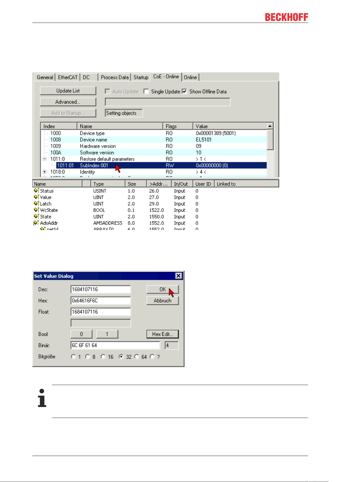
Appendix
7.4 Restoring the delivery state
To restore the delivery state for backup objects in ELxxxx terminals, the CoE object Restore default
parameters, SubIndex 001 can be selected in the TwinCAT System Manager (Config mode) (see Fig.
Selecting the Restore default parameters PDO)
Fig.37: Selecting the Restore default parameters PDO
Double-click on SubIndex 001 to enter the Set Value dialog. Enter the value 1684107116 in field Dec or the
value 0x64616F6C in field Hex and confirm with OK (Fig. Entering a restore value in the Set Value dialog).
All backup objects are reset to the delivery state.
Fig.38: Entering a restore value in the Set Value dialog
Alternative restore value
In some older terminals the backup objects can be switched with an alternative restore value: Decimal value: 1819238756, Hexadecimal value: 0x6C6F6164An incorrect entry for the restore value
has no effect.
EJ325558 Version: 1.3
Page 59

Appendix
7.5 Support and Service
Beckhoff and their partners around the world offer comprehensive support and service, making available fast
and competent assistance with all questions related to Beckhoff products and system solutions.
Beckhoff's branch offices and representatives
Please contact your Beckhoff branch office or representative for local support and service on Beckhoff
products!
The addresses of Beckhoff's branch offices and representatives round the world can be found on her internet
pages: https://www.beckhoff.com
You will also find further documentation for Beckhoff components there.
Beckhoff Support
Support offers you comprehensive technical assistance, helping you not only with the application of
individual Beckhoff products, but also with other, wide-ranging services:
• support
• design, programming and commissioning of complex automation systems
• and extensive training program for Beckhoff system components
Hotline: +49 5246 963 157
Fax: +49 5246 963 9157
e-mail: support@beckhoff.com
Beckhoff Service
The Beckhoff Service Center supports you in all matters of after-sales service:
• on-site service
• repair service
• spare parts service
• hotline service
Hotline: +49 5246 963 460
Fax: +49 5246 963 479
e-mail: service@beckhoff.com
Beckhoff Headquarters
Beckhoff Automation GmbH & Co. KG
Huelshorstweg 20
33415 Verl
Germany
Phone: +49 5246 963 0
Fax: +49 5246 963 198
e-mail: info@beckhoff.com
web:
EJ3255 59Version: 1.3
https://www.beckhoff.com
Page 60

Page 61

More Information:
www.beckhoff.com/EJ3255
Beckhoff Automation GmbH & Co. KG
Hülshorstweg 20
33415 Verl
Germany
Phone: +49 5246 9630
info@beckhoff.com
www.beckhoff.com
 Loading...