

Page 1

I/O
M
1~
L1N
M
1~
L1N
M
1~
L1N
Capacitor motor Universal motor Shaded-pole motor
Application Note DK9222-1009-0006
Bus Terminal
Speed control of single-phase AC motors
Keywords
Speed control
Bus Terminals
Energy efficiency
Square characteristic
AC motors
KL2791
In order to reduce the power consumption of single-phase AC motors, their speed can be regulated as
required. Depending on the process data, the speed can be reduced in the case of low load requirements in
order to reduce noise emissions, increase energy efficiency and prolong the service life of the units.
Effects of the change in speed
Single-phase AC motors with square load characteristic curves are often used as additional units for fans or pumps, for
example. As opposed to three-phase motors, no start-up optimisation is necessary as in the case of star-delta and adjustment
to different load cases by means of a frequency converter is often not provided for. The additional units are usually switched in
an interval orientated manner or simply activated during a certain phase of the control program. The following AC motors are
in use, depending on the application: capacitor, universal and shaded-pole motors.
Fig. 1: Controllable AC motors on the KL2791
For application notes see disclaimer on the last page
Beckhoff
New Automation Technology
1
Page 2
I/O
5421 3
Scenario 1
Volume rate of flow
Pump
Start-up
phase
1
st
cut
Constant
cut
Exit Move-out
phase
Tool drive active
Cooling lubricant consumption
Energy consumption
Application Note DK9222-1009-0006
Bus Terminal
When driving working machines whose production or conveying output can be influenced via the drive speed of the motor,
energy can be saved by means of variable speed. This particularly applies if the change in the motor speed is also linked with
large changes in the emitted mechanical output. Increase the speed – higher load, decrease – lower load. This procedure is
particularly suitable for uncontrolled units with a square load characteristic, because regulating the speed just a little brings
about a large change in energy consumption due to its square influence.
Practical example
Cooling lubricant pump in a milling machine
Two frequently occurring control scenarios are illustrated here, after which the optimisation is demonstrated. The pump is
coupled in both cases to the tool drive in order to guarantee that sufficient cooling lubrication takes place when the blades cut
into the workpiece.
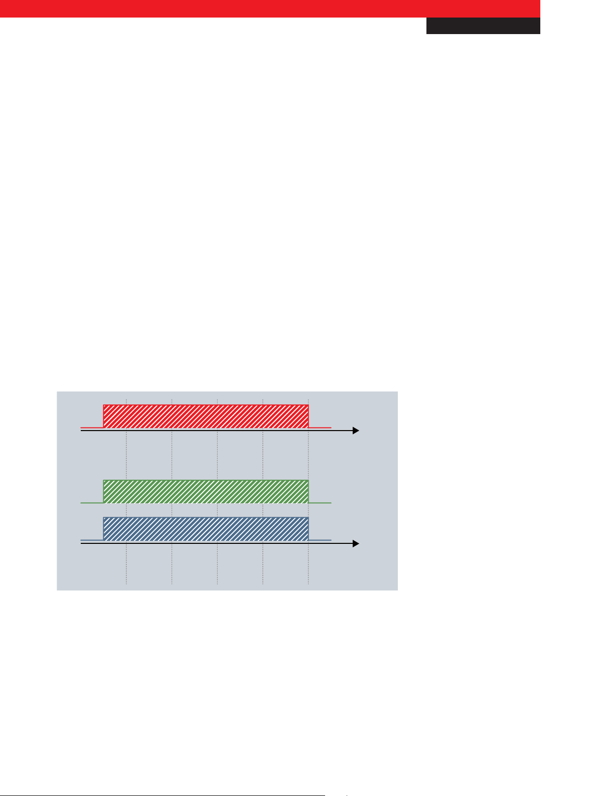
Scenario 1
Fig. 2 Need for optimised control
Cooling lubrication is fundamentally required during the runtime of the miller (tool drive) in order to achieve appropriate
surface qualities and to keep the thermal loading of the workpiece low. For this reason, the cooling lubricant circulation pump
is linked to the tool drive in order to securely guarantee pumping. There are two operating cases for the pump: Pump on | pump
off; therefore, no changes in the load take place. The pump always runs at full speed and with full power consumption, even
during the phases where the tool is moving in and moving out (1 and 5), at which time the tool drive is active, but the tool
itself is not cutting.
For application notes see disclaimer on the last page
Beckhoff
New Automation Technology
2
Page 3

Application Note DK9222-1009-0006
5421 3
Scenario 2
Volume rate of flow
Pump
Start-up
phase
1st cut Constant
cut
Exit Move-out
phase
Tool drive active
Cooling lubricant consumption
Energy consumption
Bus Terminal
Scenario 2
I/O
Fig. 3 Fractional optimised control
Similar to the example above, the pump is linked logically to the tool drive. However, additionally, there is a valve to regulate
the flow rate for different load cases and to prevent pumping when the tool is driving in. Although the cooling lubricant
consumption is thus optimised, the pump is still running at 100 % utilisation, even though the flow rate is only minimal.
Furthermore, a dynamic pressure builds up at the valve due to the constantly running pump, so that when the valve is opened
the cooling lubricant shoots out before the normal pumping pressure has been established.
For application notes see disclaimer on the last page
Beckhoff
New Automation Technology
3
Page 4

I/O
5421 3
KL2791
Volume rate of flow
Pump
Start-up
phase
1
st
cut Constant
cut
Exit Move-out
phase
Tool drive active
Cooling lubricant consumption
Energy consumption
Application Note DK9222-1009-0006
Bus Terminal
Optimisation – speed control using the KL2791
In neither case the power consumption of the pump is affected; therefore, the use of the single-phase AC motor terminal makes
sense in order to achieve a reduction in the consumed power.
Fig. 4 Optimised control with the KL2791
Using the KL2791 single-phase AC motor terminal, a single-phase AC motor with a maximum power consumption of 0.1 kW
can be operated with speed control depending on the process data. L1 and N of the motor are wired directly to the terminal;
this is in turn integrated in the control environment via a Bus Coupler or connected directly to an embedded device.
The controller specifies the set value for the motor speed in the form of a 16-bit word; the speed is regulated internally in the
terminal: the motor is switched on and off with a practice-proven mains-synchronous pattern, so that the motor consumes less
power and the speed falls significantly. This method is well suited to motors with fixed loads, such as pumps and fans, in order
to achieve a control range for the flow rate from 10 % to 100 %.
– 1-channel AC motor speed controller, 230 V AC, 100 VA www.beckhoff.com/KL2791
– The modular fieldbus system for automation www.beckhoff.com/Busterminal
This publication contains statements about the suitability of our products for certain areas of application. These statements are based on typical features of our products. The examples shown in this publication are for demonstration purposes only. The information provided herein should not be regarded as specific operation characteristics. It is incumbent on the
customer to check and decide whether a product is suit-able for use in a particular application. We do not give any warranty that the source code which is made available with this
publication is complete or accurate. This publication may be changed at any time with-out prior notice. No liability is assumed for errors and/or omissions. Our products are described
in detail in our data sheets and documentations. Product-specific warnings and cautions must be observed. For the latest version of our data sheets and documentations please visit
our website (www.beckhoff.com).
© Beckhoff Automation GmbH, October 2009
The reproduction, distribution and utilisation of this document as well as the communication of its contents to others without express authorisation is prohibited. Offenders will be
held liable for the payment of damages. All rights reserved in the event of the grant of a patent, utility model or design.
Beckhoff
New Automation Technology
4
 Loading...