

Page 1

I/O
Application Note DK9222-0909-0012
Bus Terminal
Pulse Train Output Terminal KL2521
Keywords
Encoder simulation
Pulse Train
Stepper motor
Pulse direction signal
Fieldbus substitute
Servo controller
Servo drive
Frequency converter
KL2521
This Application Example describes the control and positioning of drives through pulse patterns (pulse
train), which is common practice in Asia and the USA. In servo or stepper motors this technique is used for
realising simple positioning tasks. The pulses can be generated in the PLC or an associated I/O module, e.g.
Bus Terminal KL2521. It modulates a binary signal with a specified frequency that can be used directly for
control purposes.
The idea is that with the new KL2521 Pulse Train output terminal, Beckhoff are using simple pulses sent to stepper motors
and servo drives to implement digital technology for precise positioning tasks. To do this, the electronic Bus Terminal converts
a binary signal to a frequency, feeding this, electrically isolated from the terminal bus, to the positioning drive. The frequency
is preset by a 24 bit value from the automation unit. The advantage over conventional technology, such as an analog ± 10 V
interface, is that the Bus Terminal‘s high output frequency of 500 kHz allows the operation of the fastest servo drives currently
available. In contrast to analog technology, the set value signal is communicated without any offset drift. The 24 bit resolution
guarantees a high precision, in steps of 10 mHz. This means that set values can be specified in fine, almost continuous, steps.
In practice, the desired maximum output frequency is entered into a register, and then the frequency output can be used much
like a ± 10 V output by using 16 bits of the process image.
For application notes see disclaimer on the last page
Beckhoff
New Automation Technology
1
Page 2
Application Note DK9222-0909-0012
Bus Terminal KL2521
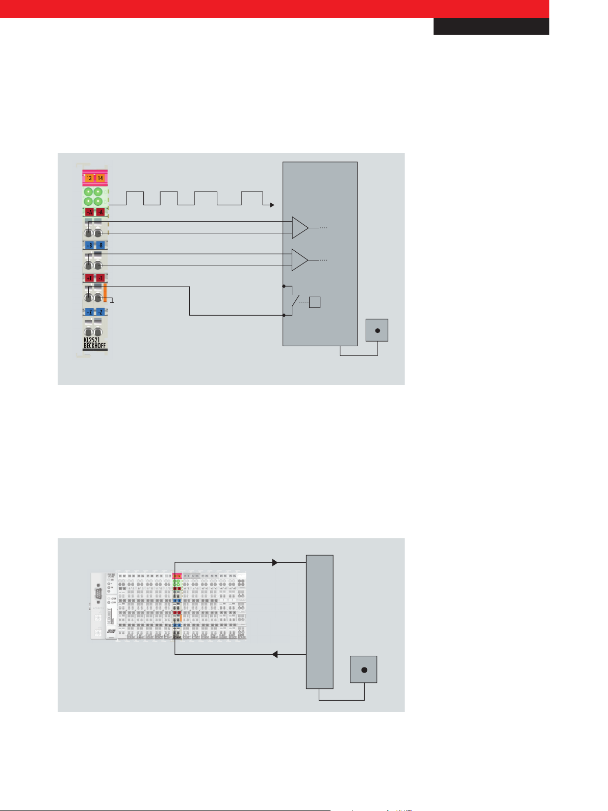
Set value outputs by
variable frequency
+A
-A
+B
-B
24 V DC
Target/
following error
i. e.
Servoamplifiers,
frequency converters
Servomotors
Set value outputs
Target output
Bus Terminal
I/O
Fig. 1 Connections of the KL2521 pulse train terminal
Set value outputs and the acquisition of actual positions with just one Bus Terminal
The use of the Pulse Train technology to position drives is primarily used in Asia and in the USA. Its origins lie in the
methods for driving stepper motors. The wide acceptance and easy use of the technology resulted in its application to higher
power sectors of drive technology. The interface using Pulse Train technology is nowadays also applied to servoamplifiers
and frequency converters. The user can employ a consistent software and hardware interface, from micro-steppers up to
highpowered servo-drives.
Fig. 2 Set value outputs and the acquisition of actual positions with just one Bus Terminal
For application notes see disclaimer on the last page
Beckhoff
New Automation Technology
2
Page 3

I/O
A
B
A
B
A
B
Frequency modulation
Pulse/direction signals
Incremental encoder simulation
Application Note DK9222-0909-0012
Bus Terminal
In the Pulse Train technology, the provision of the set value and the validation of the actual position is implemented with
the aid of just one digital Bus Terminal. The actual position, which is otherwise acquired with the aid of incremental encoder
techniques, is calculated, depending on the specified set value frequency using, for instance, the TwinCAT software PLC/NC
(Figure 2). A difference between the set and actual value is indicated to the Bus Terminal using the target or following error
digital output which is present in all common servoamplifiers.
The KL2521 Pulse Train Bus Terminal supports three different frequency pulse patterns (Figure 3). These may be selected in
using the KS2000 configuration software, or by the higherlevel controller.
Fig. 3 frequency pulse patterns
The pulse patterns are output through the two channels, A and B. They correspond to all usual input circuits::
– Frequency modulation: rotation to the right is associated with output of the frequency signal on channel A, while rotation
to the left is associated with output on channel B. The inactive channel remains at a logical „low“ state.
– Pulse/direction signals: the frequency pattern is always output on channel A, the direction of rotation being indicated by the
„high“ or „low“ level on channel B.
– Incremental encoder simulation: channels A and B output a signal with a 90° phase shift. The shift from A to B is positive
or negative, thus encoding the direction of rotation. The output signal is thus exactly the same as that of an incremental
transducer. The advantage here is the possibility of directly driving frequency converters through the „synchronous axes“
signal input (Figure 4). Ontop of the simple positioning, this arrangement permits a master/slave structure. Users can
therefore couple this system to fieldbusses through existing interfaces - i.e. without additional costs.
For application notes see disclaimer on the last page
Beckhoff
New Automation Technology
3
Page 4

Application Note DK9222-0909-0012
FU
FU FU
Set value outputs
Signal output „synchronous axes“
Bus Terminal
These 3 different pulse patterns can also be inverted, thus permitting ideal adaptation to the input circuit.
I/O
Fig. 4 Synchronisation of several frequency converters via incremental encoder simulation
The new Bus Terminal does more than simply make a large number of analog interfaces superfluous. The possibility of using the
automatic step counting to implement closed control loops is of even greater significance. The digital technology offers more
functions in comparison to the expensive evaluation involved in analog technology, and at lower cost.
Supplementary functions integrated into the new Bus Terminal support operation and reduce the controller‘s power
requirement. Optimal operation of a stepper motor is easily possible through the specification of a ramp. Just two parameters,
the ramp start frequency and the ramp run-up time, are necessary to initialise the Bus Terminal. The controller now only needs
to specify the frequency. The Bus Terminal performs acceleration and braking tasks. The frequency change is calculated directly
in the Bus Terminal, and takes place, bumplessly at time intervals of 2 ms. The controller‘s computing load is thus reduced,
which permits a number of axis controllers to be implemented using just one intelligent Bus Terminal Controller.
The output terminal can be configured using the associated Bus Coupler or the controller. The output stage is compatible with
RS422. It can, however, also be operated with 24 V DC signals. Either operating mode can be used without the need for a
configuration switch or for parameterisation. The signal state is indicated by light emitting diodes. The LEDs are driven in time
with the outputs and each displays an active output.
– Pulse train output terminal RS422/24 V DC www.beckhoff.com/KL2521
– The modular fieldbus system for automation www.beckhoff.com/Busklemmen
For application notes see disclaimer on the last page
Beckhoff
New Automation Technology
4
Page 5

Application Note DK9222-0909-0012
Bus Terminal
I/O
This publication contains statements about the suitability of our products for certain areas of application. These statements are based on typical features of our products. The examples shown in this publication are for demonstration purposes only. The information provided herein should not be regarded as specific operation characteristics. It is incumbent on the
customer to check and decide whether a product is suit-able for use in a particular application. We do not give any warranty that the source code which is made available with this
publication is complete or accurate. This publication may be changed at any time with-out prior notice. No liability is assumed for errors and/or omissions. Our products are described
in detail in our data sheets and documentations. Product-specific warnings and cautions must be observed. For the latest version of our data sheets and documentations please visit
our website (www.beckhoff.com).
© Beckhoff Automation GmbH, September 2009
The reproduction, distribution and utilisation of this document as well as the communication of its contents to others without express authorisation is prohibited. Offenders will be
held liable for the payment of damages. All rights reserved in the event of the grant of a patent, utility model or design.
Beckhoff
New Automation Technology
5
 Loading...