

Page 1
XFC
Application Note DK9222-0711-0051
XFC technology microincrements
Microincrements | IP67-related solutions
Keywords
microincrements
Distributed Clocks
EtherCAT
EtherCAT Box
XFC
IP 67
EP5101
encoder
This application example describes how an EP5101 EtherCAT Box can be used in a harsh industrial
environment (IP 65/67) to maximize the physical resolution of an incremental encoder. The number of
counted encoder segments can be output in more detail with a data width of just 8 bit, i.e. 256 times.
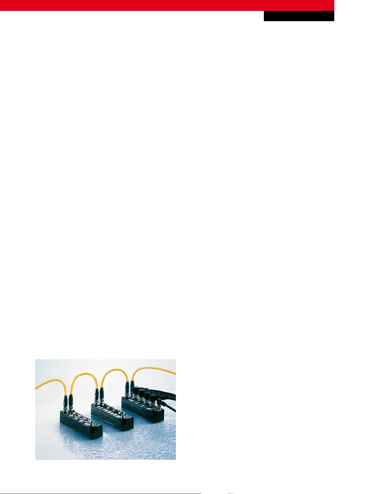
The resilient IP 67 I/O system from Beckhoff
The Beckhoff EtherCAT Box line delivers EtherCAT I/O technology without requiring a control cabinet. All modules from the IP
67 series have an integrated direct EtherCAT interface, so that the protocol’s high performance is retained right down to each
module. This opens up new options in the IP 67 world: fast process data communication with eXtreme Fast Control (XFC),
high precision measurement technology and drive functions integrated into I/O solutions directly in the field. With dimensions
of only 126 x 30/60 x 26.5 mm (H x W x D) the modules are exceptionally small and are, therefore, particularly suitable for
applications where available space is limited.
For application notes see disclaimer on the last page
New Automation TechnologyBeckhoff
1
Page 2
XFC
CHA
CHB
2fold
4fold
CH
N
Application Note DK9222-0711-0051
XFC technology microincrements
Technical background
The incremental encoder is the main link between the mechanical system and the control system for monitoring mechanical
movements. Incremental encoders convert linear or rotary movements into signals that can be analyzed electrically. For rotary
movements, a certain number of light/dark segments applied to a pulse disc are scanned with a light beam. A scannable scale
arranged in the direction of motion is used for capturing linear movements. The accuracy of the returned position is limited by
the encoder resolution. For rotary movements, the resolution corresponds to the quotient of revolution (360°) and number of
segments. It indicates the smallest possible measurable difference between two positions. The more segments, the higher the
resolution and the more precise the position information. A standard encoder has 1000 lines, resulting in an accuracy of 360° /
1000 = 0.36°. This means a rotary movement can be monitored with a precision of ±0.36°. In many cases, this is adequate for
simple positioning tasks, although a finer resolution is required in order to monitor axis synchronism in addition to the position.
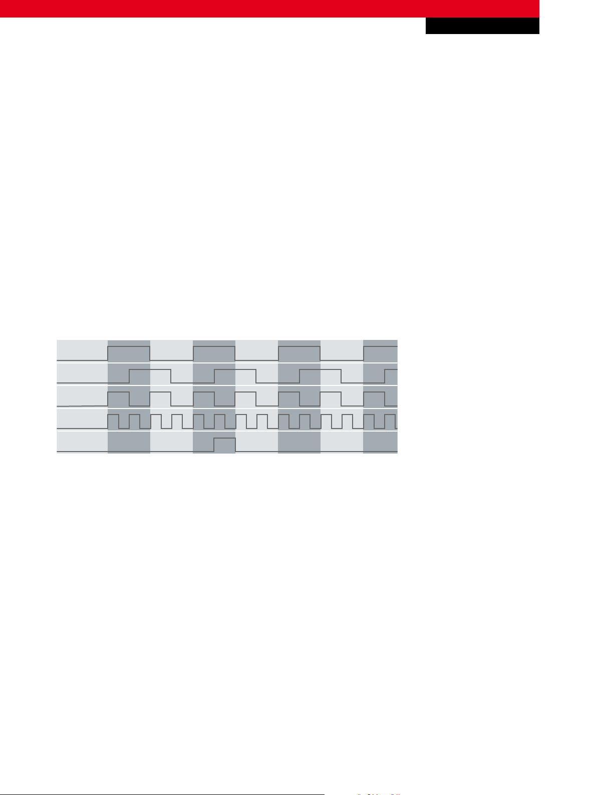
Fig. 1 Encoder signals with different resolutions
Physical improvement of the resolution through maximization of the encoder segments is only feasible to a certain degree,
since manufacturing tolerances and operating conditions increase the costs of the encoder. A simple and effective way of
maximizing the resolution is to use a second detection point. With two signals that are offset by 90°, three additional edges
are available for detection. They can be used to detect the direction of rotation in addition to the position, and an additional
reference signal for zeroing is output once per revolution. Analysis of these additional edges can refine the resolution by a
factor of 4 (360° / 4 * 1000 = 0.09°), which is why this principle is referred to as quadrature encoder.
Axis synchronism monitoring
Axis synchronism is monitored through cyclic position polling and interpolation of these values within the PLC. The timebase
for the interpolation is provided by the strict cycle-linked processing of the instructions in the PLC. With a cycle time of 1 ms
(which is common for motion applications), the positions are scanned with a timebase of 1 ms. However, the real encoder
scanning intervals are not as rigid as those of the PLC and vary. The reason for the irregularity is inherent to the functional
principle variation of the fieldbus transfer times (jitter) and the encoder inaccuracy with ±½ edge. Since the PLC does not take
this discontinuity of the polling intervals into account and assumes a constant interval duration, the position representation
For application notes see disclaimer on the last page
New Automation TechnologyBeckhoff
2
Page 3
XFC
0
2
4
6
8
10
12
14
16
n n + 1 n + 2 n + 3 n + 4 n + 5 n + 6 n + 7
Actual course Process image
Cycles
Application Note DK9222-0711-0051
XFC technology microincrements
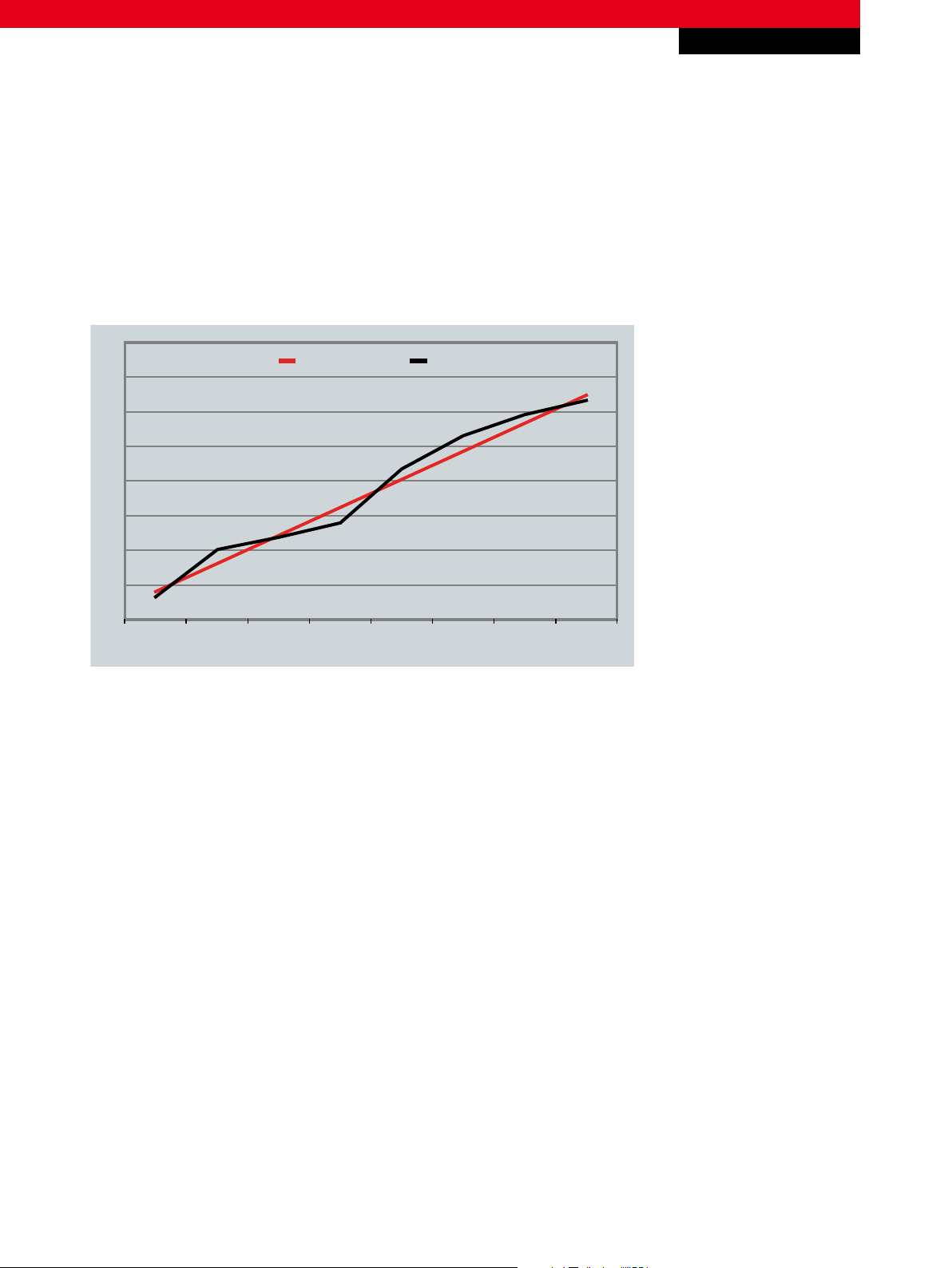
in the process image of the PLC may be unsteady even if the axis is, in fact, synchronous. This only virtual deviation can have
three different effects:
Diagram 1 Asynchronism according to process image
1st case:
Although, in reality, the axis runs absolutely uniformly, the process image shows a non-uniform movement (see Diagram 1)
For application notes see disclaimer on the last page
New Automation TechnologyBeckhoff
3
Page 4

Application Note DK9222-0711-0051
0
2
4
6
8
10
12
14
16
n n + 1 n + 2 n + 3 n + 4 n + 5 n + 6 n + 7
Actual course Process image
Cycles
0
2
4
6
8
10
12
14
16
n n + 1 n + 2 n + 3 n + 4 n + 5 n + 6 n + 7
Actual course Process image
Cycles
XFC technology microincrements
XFC
Diagram 2 Amplified asynchronism according to process image
2nd case:
While the axis only runs slightly unevenly, the effect is amplified in the process image (see Diagram 2)
Diagram 3 Equalising asynchronism according to the process image
3rd case:
The axis runs unevenly, the process image equalizes the non-uniform movement (see Diagram 3)
For application notes see disclaimer on the last page
New Automation TechnologyBeckhoff
4
Page 5

XFC
Application Note DK9222-0711-0051
XFC technology microincrements
Synchronization of the strictly cyclical polling through the distributed clock function
High uniformity of the polling intervals can be achieved by using a local clock generator in the EtherCAT slaves, for example,
the distributed clock function within EtherCAT (see Fig. 2). This principle is based on measuring the protocol run times within
the bus and adjustment of the clock generator clocks in the individual fieldbus slaves. With DC, any run-time difference is
known exactly and can be compensated. The polling intervals of the EtherCAT slaves are thus adapted to the strictly cyclic
operation mode of the PLC. For distributed clock function, see the distributed clocks system description which is available from
the download area under www.beckhoff.com/english/download/ethercat.htm.
Fig. 2 Local clock generators in the field
For application notes see disclaimer on the last page
New Automation TechnologyBeckhoff
5
Page 6

XFC
Submitted
values
per cycle
Encodersignal
Submitted
values
by using
microincrements
4
5
6
7
3
3.05 4.6 5.8 6.5 7.48
Application Note DK9222-0711-0051
XFC technology microincrements
Practical example | Virtual maximization of the physical encoder resolution through
microincrements
The semi-edge inaccuracy of the encoder is eliminated by using the microincrement mode of the Beckhoff EP5101 EtherCAT
Box with encoder interface. In this mode, the EtherCAT Box automatically interpolates the position scans to be transferred
over a width of 8 bits. Therefore, this mode offers a 256 times higher resolution than the encoder is able to provide physically.
The microincrement mode is only suitable for motion analyses, because for interpolation within the EtherCAT Box, the position
is sampled with a significantly higher resolution than is passed on to the fieldbus in interpolated form. The principle of
interpolation in the EtherCAT Box requires a minimum speed, i.e. microincrements cannot be analyzed at (or near) standstill.
Fig. 3 Different encoder signals resolutions (with and without microincrements)
The EP5101 EtherCAT Box is an interface for the direct connection of incremental encoders with differential inputs (RS485).
Due to the optional interpolating microincrement function, the EP5101 can supply even more precise axis positions for dynamic
axes. In addition, it supports the synchronous reading of the encoder value together with other input data in the EtherCAT
system via high-precision EtherCAT distributed clocks (DC). The encoder is connected via an 8-pin M12 socket (EP5101-0002)
or via a 15-pin D-sub socket (EP5101-0011).
For application notes see disclaimer on the last page
New Automation TechnologyBeckhoff
6
Page 7

Application Note DK9222-0711-0051
XFC technology microincrements
Connector assignment
EP5101-0002
4
4
321
321
1 | GND
2 | VCC
3 | A
4 | /A
5 | B
6 | /B
7 | C
8 | /C
2 412
4
3
3 1
IN OUT
|
EP5101-0002
4
4
321
321
2 412
4
3
3 1
IN OUT
1 | A
2 | GND
3 | B
4 | VCC
5 | n.c.
6 | n.c.
7 | /C
8 | Latch
9 | /A
10 | GND
11 | /B
12 | VCC
13 | /ERR
14 | C
15 | Gate
Fig. 4 Connector assignment of the EP5101 EtherCAT Box
XFC
– Incremental encoder interface for IP 67 www.beckhoff.com/EP5101
– Control architecture for highest performance www.beckhoff.com/XFC
– EtherCAT Extends its Reach into the IP 67 World www.beckhoff.com/EtherCAT-Box
– EtherCAT www.beckhoff.com/EtherCAT
This publication contains statements about the suitability of our products for certain areas of application. These statements are based on typical features of our products. The examples shown in this publication are for demonstration purposes only. The information provided herein should not be regarded as specific operation characteristics. It is incumbent on the
customer to check and decide whether a product is suit-able for use in a particular application. We do not give any warranty that the source code which is made available with this
publication is complete or accurate. This publication may be changed at any time with-out prior notice. No liability is assumed for errors and/or omissions. Our products are described
in detail in our data sheets and documentations. Product-specific warnings and cautions must be observed. For the latest version of our data sheets and documentations please visit
our website (www.beckhoff.com).
© Beckhoff Automation GmbH, July 2011
The reproduction, distribution and utilisation of this document as well as the communication of its contents to others without express authorisation is prohibited. Offenders will be
held liable for the payment of damages. All rights reserved in the event of the grant of a patent, utility model or design.
New Automation TechnologyBeckhoff
7
 Loading...