

Page 1

I/O
Application Note DK9222-0411-0038
I/O, Building Automation
Keywords
KL6401
TwinCAT
Building Automation
KS2000
LON
Line coupler
SNVT
Transceiver
Integration of LON networks into a PC-based building
automation system
This application example from the ’Building Automation Sub-bus Systems’ series conveys the basic
principles of LonWorks (LON for short) and the integration of LON devices into the PC-assisted building
automation system via the Beckhoff KL6401 LON Bus Terminal. LON is a local sensor/actuator network in
which the devices communicate directly with one another via network variables (SNVTs). The typical area
of use of LON is the trade-spanning automation of functional buildings, in which the modular structure
of LON allows flexible changes and conversions. Besides the KS2000 configuration software for the
parameterization of the SNVTs, the LON user requires a LON tool in order to establish the ’binding’ between
the individual devices.
1. LON
LonWorks (Local Operating Network: LON for short) is a decentralized network for intelligent sensors, actuators and operating
devices with a large field of application; its main use is in the automation of functional buildings. Through transmission media
such as twisted pair wires, sensors and actuators can communicate with one another as desired from any point to any other
point on the basis of network variables (SNVTs, Standard Network Variable Type). Each LON device contains a microprocessor,
the neuron, which controls the communication. Each neuron has a unique identification number, the neuron ID, which
corresponds to the physical address and is set in the factory.
LON is typically used for trade-spanning networking within the building automation; a LON network consists of up to 32,000
intelligent network nodes. LON is an international standard on account of its widespread use worldwide. It is mainly used in
the automation of functional buildings, since devices developed by different manufacturers from different systems and trades
For application notes see disclaimer on the last page
New Automation TechnologyBeckhoff
1
Page 2

Application Note DK9222-0411-0038
I/O, Building Automation
can be integrated in one system. Further areas of application are industrial and process automation, supply and disposal,
energy technology, traffic control, etc.
2. Master versions
LON is a typical multi-master system, in which each device on the bus can have event-controlled transmission. The neuron
controls communication
3. Topologies
LON is a classic line bus, but it can follow any topology. Since it is possible to choose between star, ring, tree or classic line
I/O
structures, this often gives rise in practice to free topologies that are oriented to existing structures in buildings or plants. The
following are used for segmenting such free topologies:
Repeater | for physical amplification with no processing function
–
– Router | for the connection of subnetworks
– Bridges | connection of domains
LON devices communicate via different transmission media; as a result, the range of a LON network depends directly on the
transmission medium. If all guidelines are taken into account in the topology structure, a LON network can have a virtually
unlimited size. With the classic TP wiring (twisted pair – two-wires twisted together) the maximum bus length is 1300 m.
For application notes see disclaimer on the last page
New Automation TechnologyBeckhoff
2
Page 3
I/O
max. 63 nodes
max. 63 nodes
repeater
router
max. 127 nodes + 1 repeater
subnet
r
outer
r
outer
repeater
router
max. 255 subnets per domain, each with 127 nodes = 32385 devices
Application Note DK9222-0411-0038
I/O, Building Automation
.1 Network structure
3
A LonWorks network is divided into the domain, subnet and nodes. There may be a maximum of 255 subnets (subnetworks) in
the domain – a subnet in turn may consist of a maximum of 127 nodes (LON nodes). Additionally, a domain may consist of a
maximum 32385 LON nodes, i.e. LON devices. Several domains can be connected if necessary. In principle, however, only nodes
within a domain can communicate directly with one another. Each node in a network has a unique logical address, which is
divided into these three hierarchical levels: Domain ID, Subnet ID and Node ID.
Fig. 1 Structure of LON networks
Components such as routers, bridges and repeaters are used for the construction of LON networks.
Repeaters are physical amplifiers with no processing function. They are used to achieve greater transmission distances and/or
to extend the maximum permissible number of nodes of 64 nodes per 2-wire segment when using FTT-10-transceivers.
Routers are devices with several bus connections, which are used to interconnect several subnetworks. Telegrams received on
one side are normally transmitted again on the other side by the router – and vice versa, of course. The router can also perform
the function of a filter, a pathfinder or a post distributor.
4. Communication
LON nodes communicate directly with one another on the basis of the LonTalk® protocol, without going through a central
control unit. Data exchange takes place by means of SNVTs: they form the logical interface between two nodes. SNVTs consist
of three sections: unit, range of values and resolution, which must be configured identically in both nodes for unambiguous
interpretation of the data.
For application notes see disclaimer on the last page
New Automation TechnologyBeckhoff
3
Page 4

Application Note DK9222-0411-0038
I/O, Building Automation
5. Power supply
Two types of power supplies are possible in the LON network structure: FTT and LPT.
I/O
Transmission type
TP/FT-10
TP/XF-1250
PL-20
IP-10
Physical layer
Twisted Pair
Free/Bus topology
optional Linkpower
Twisted pair
Bus topology
Power line
LonWorks-over-IP
Table 1 Transmission types in LON
Bit rates
78 kbps
1.25 Mbps
5.4 kbps
depending
on IP network
Tranceiver
FTT-10
FFT10A
LPT-10
TPT/XF-1250
PLT-20
PLT-21
PLT-22
depending
on IP network
Max. Number
of devices
64...128
64
depending on
the environment
depending
on IP network
Max. extent
500 m (free topology)
2200 m (bus topology)
125 m
depending on
the environment
depending
on IP network
6. KL6401 LON Bus Terminal
The KL6401 LON Bus Terminal enables the direct connection of LON devices for the binding of LON networks to the PLC.
It supports the transmission standard TP/FT-10 or can be used under FTT-10 and LPT-10 transceivers (TP – Twisted Pair, FT
– Free Topology). Data exchange between the most diverse systems and a LON network is simplified, since the network
variables of the connected devices are available to the Bus Coupler or the higher level bus system. The LON terminal thereby
works independently of the bus system employed and the use of several KL6401 on one Bus Coupler or on one Bus Terminal
Controller is possible. 62 SNVTs are supported per KL6401 LON Bus Terminal. All SNVT types are configurable as input or output
variables using KS2000 software. The KS2000 software generates the required XIF file that is integrated in a LON tool.
Information on the use of the KL6401:
The KL6401 can only be used in conjunction with TwinCAT software and the TwinCAT library. No Bus Couplers from the BK
series are supported if the KL6401 is used under a controller other than TwinCAT. The use of the KL6401 LON Terminal in
combination with an Embedded PC from the CX series is possible only in conjunction with TwinCAT PLC. The TwinCAT PLC
library LON is included (free of charge) in the TwinCAT installation package.
7. Software
The KL6401 terminal offers the possibility to configure a maximum of 62 SNVTs. These 62 SNVTs can be configured in any
combination and as inputs and/or outputs as well. The SNVTs are configured using the KS2000 configuration software, which,
apart from configuration, is also necessary for the operation of the KL6401 LON Bus Terminal. In addition, a LON tool (e.g.
Echelon ‘LonMaker’) is needed in order to carry out the ‘binding’ of the corresponding SNVTs.
For application notes see disclaimer on the last page
New Automation TechnologyBECKHOFF
4
Page 5

I/O
Application Note DK9222-0411-0038
I/O, Building Automation
It should be noted when binding that, as a matter of principle, only SNVTs of the same type and with an identical
parameterization can be connected to each other. For example, a temperature value will only be transmitted correctly from
one node to another if the resolution and the unit of the temperature value are identically parameterized in both nodes. The
complete configuration sequences are described in detail in the documentation for the KL6401 terminal.
7.1 KS2000
For the commissioning of a LON application, the KL6401 LON Terminal is parameterized accordingly using the KS2000
terminal configuration software. This is followed by the parameterization of the necessary SNVTs using KS2000 and loading
to the terminal. After the activation of the project, the terminal must be switched off once in order to ensure that all data in
the terminal’s internal memory are deleted. After switching off, the XIF file for the LON tool can be exported. In addition, the
parameterization carried out can also be saved as a BLC file (backup). The existing configuration can be easily duplicated;
furthermore, a backup of the SNVTs is saved.
Fig. 2 View of the configuration dialog in the KS2000 terminal configuration software
For application notes see disclaimer on the last page
New Automation TechnologyBeckhoff
5
Page 6

I/O
Application Note DK9222-0411-0038
I/O, Building Automation
.2 LON tool
7
A LON tool is required in order to create the binding (e.g. ‘LonMaker integration tool’ by Echelon). The LON tool serves the
development, installation, operation and maintenance of open control networks from various manufacturers. Since the SNVTs
are pre-specified function blocks, the binding is a kind of input/output assignment in which the user specifies which actuators
are triggered by which sensors.
Fig. 3 View of the LonMaker® ‘binding’ tool by Echelon
For application notes see disclaimer on the last page
New Automation TechnologyBeckhoff
6
Page 7

Application Note DK9222-0411-0038
I/O, Building Automation
7.3 TwinCAT
For integration in TwinCAT, the function block FB_LON_KL6401 is called once in the PLC cycle. The documentation contains
further information.
I/O
Fig. 4 Function block for LON communication in the KL6401 via TwinCAT
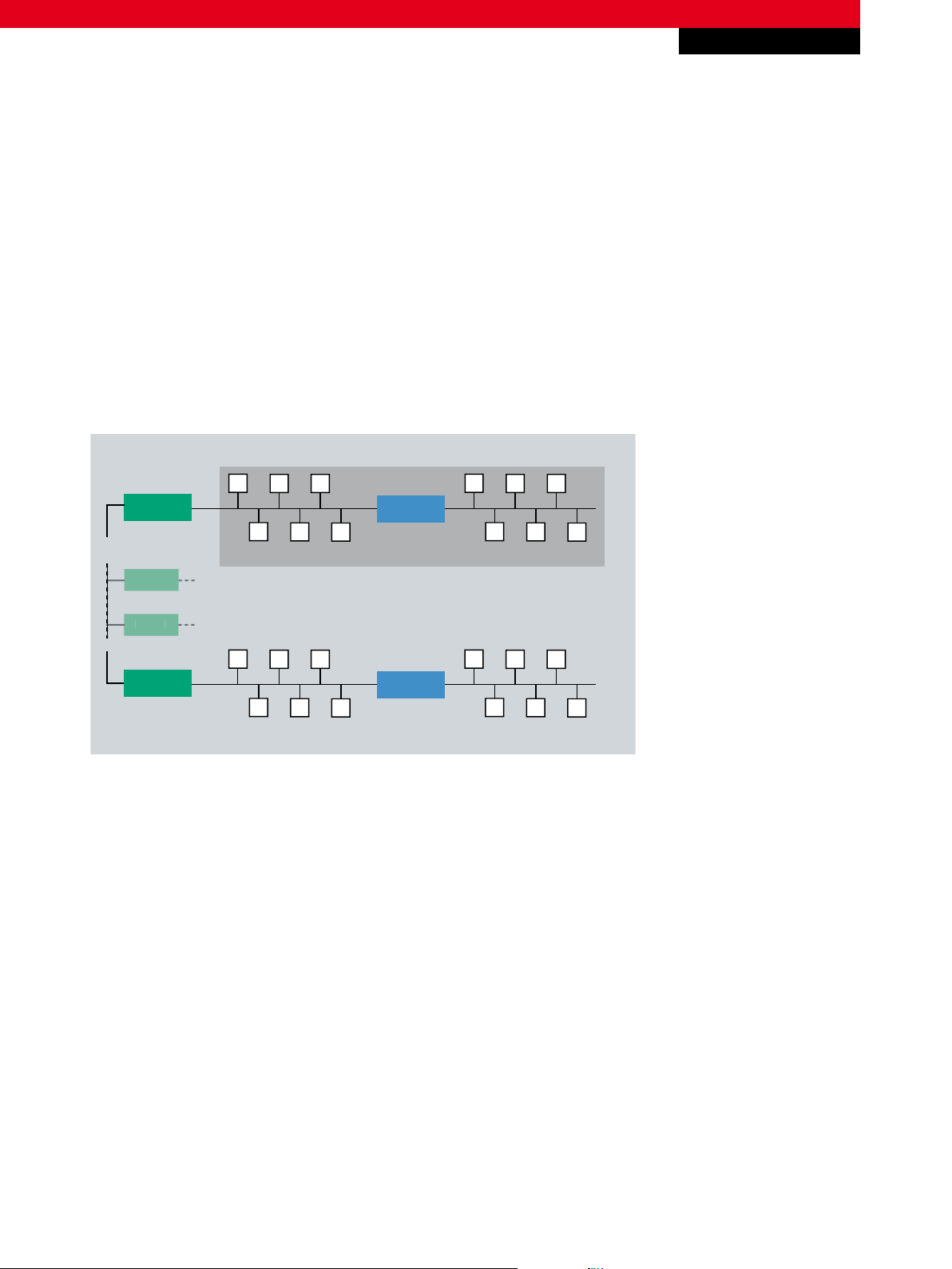
8. Practical example
LON: Minimization of the cabling due to structured Ethernet cabling
Ethernet (BMS)
CX1010
BK9000
KL6401
CU2008
KL6401
Connection of further floors
KL6401
BK9000
BK9000
Fig. 5 Connection of LON peripheral devices for trade-spanning communication
For application notes see disclaimer on the last page
New Automation TechnologyBECKHOFF
7
Page 8

I/O
Application Note DK9222-0411-0038
I/O, Building Automation
The use of LON enables efficient, trade-spanning and flexible automation solutions to be achieved, whose structure can be
changed with little programming. A typical area of application for LON, among others, is the control of HVAC peripheral devices
in offices and production facilities. Apart from low material costs, the use of Ethernet to connect the individual subnets within a
domain allows longer ranges and enables the passing of error and status messages to the BMS via the fast Ethernet protocol.
– LON Bus Terminal www.beckhoff.com/KL6401
– TwinCAT PLC library LON www.beckhoff.com/english/twincat/twincat_plc_lon.htm
– Configuration software www.beckhoff.com/KS2000
– Beckhoff Building Automation www.beckhoff.com/building
– Web page of LonMark International www.lonmark.org
This publication contains statements about the suitability of our products for certain areas of application. These statements are based on typical features of our products. The examples shown in this publication are for demonstration purposes only. The information provided herein should not be regarded as specific operation characteristics. It is incumbent on the
customer to check and decide whether a product is suit-able for use in a particular application. We do not give any warranty that the source code which is made available with this
publication is complete or accurate. This publication may be changed at any time with-out prior notice. No liability is assumed for errors and/or omissions. Our products are described
in detail in our data sheets and documentations. Product-specific warnings and cautions must be observed. For the latest version of our data sheets and documentations please visit
our website (www.beckhoff.com).
© Beckhoff Automation GmbH, April 2011
The reproduction, distribution and utilisation of this document as well as the communication of its contents to others without express authorisation is prohibited. Offenders will be
held liable for the payment of damages. All rights reserved in the event of the grant of a patent, utility model or design.
New Automation TechnologyBECKHOFF
8
 Loading...