

Page 1

I/O
Application Note DK9222-0310-0010
Bus Terminals
Keywords
Lighting control
Universal dimmer
Low-voltage halogen dimmer
Ethernet dimmer
Leading edge phase control
Trailing edge phase control
Short-circuit-proof
Network-capable
KL2751
KL2761
Basic principles of the dimmer function and network
capability
This application example describes the basic principles of the dimming of light, the important aspects
concerning the individual types of dimmer (leading edge phase control, trailing edge phase control,
universal) and the advantages of the use of a network-capable universal dimmer.
Basic principles
In order to dim the intesity of a light bulb, the flow of current is reduced, which corresponds to a regulation of the brightness.
Three principles can be employed for this: voltage divider, leading edge phase control and trailing edge phase control. The
voltage divider is not used because of its energetic inefficiency: the voltage for the light generation is divided by an adjustable
pre-resistor; the proportion of the unused power to generate light is dissipated by the resistor and converted into heat energy.
Phase control dimmers work considerably more efficiently, since in this case the current is switched on and off by means
of electronic circuits. The light bulb is switched at a frequency that is not discernable to the eye. Since the flow of current is
interrupted during the dead time, the power dissipation is considerably reduced in comparison with the voltage divider. The
ratio of the switch-on time to the switch-off time determines in both principles the flow of current or the quantity of emitted
light. The basis of both principles is the sine wave of the mains voltage. At a frequency of 50 Hz the voltage changes its polarity
100 times per second; it therefore also reaches the zero crossing point, at which there is freedom from both current and
voltage for a brief moment, 100 times per second.
Dimmer types
Electronic phase control dimmers control the effect produced by the light source by only letting the current flow over a certain
section of the alternating voltage half-waves. In the case of 230 V general-purpose lamps (‘incandescent lamps’), the operating
For application notes see disclaimer on the last page
Beckhoff
New Automation Technology
1
Page 2
Application Note DK9222-0310-0010
R, L, C R, L, C R L C
t
u
i
Leading edge phase control
Voltage u,
Current i
Bus Terminals
mode of the dimmer is unimportant because of the purely ohmic load. For all illuminants that are connected via electronic
ballasts (EBs), such as low-voltage halogen spots, the construction of the transformer is decisive for the applied control
principle. It should also be noted that mixed loads are not controlled: an ohmic load cannot be controlled together with an
inductive load in a the same circuit, even if the dimmer is suitable for both load types. The dimmer type and the type of the
connectable loads are identifiable by pictograms.
Fig. 1 Meaning of the pictograms: R = ohmic, L = inductive, C = capacitive, descending triangle = leading edge phase control,
ascending triangle = trailing edge phase control
I/O
Inductive loads – leading edge phase control
Low-voltage halogen lamps with conventional, inductive (= wire-wound) transformers are controlled by thyristor dimmers
based on leading edge phase control. In the leading edge phase control technique, the switch-on point of the switch is changed
in relation to the mains voltage half-wave. The thyristor thereby becomes conductive at a controllable point within the voltage
half-waves; the flow of current is automatically interrupted at the next zero crossing of the sine half-wave. This ensures that no
inductive voltage peak occurs when switching off.
Fig. 2 Change of switch-on point with leading edge phase control
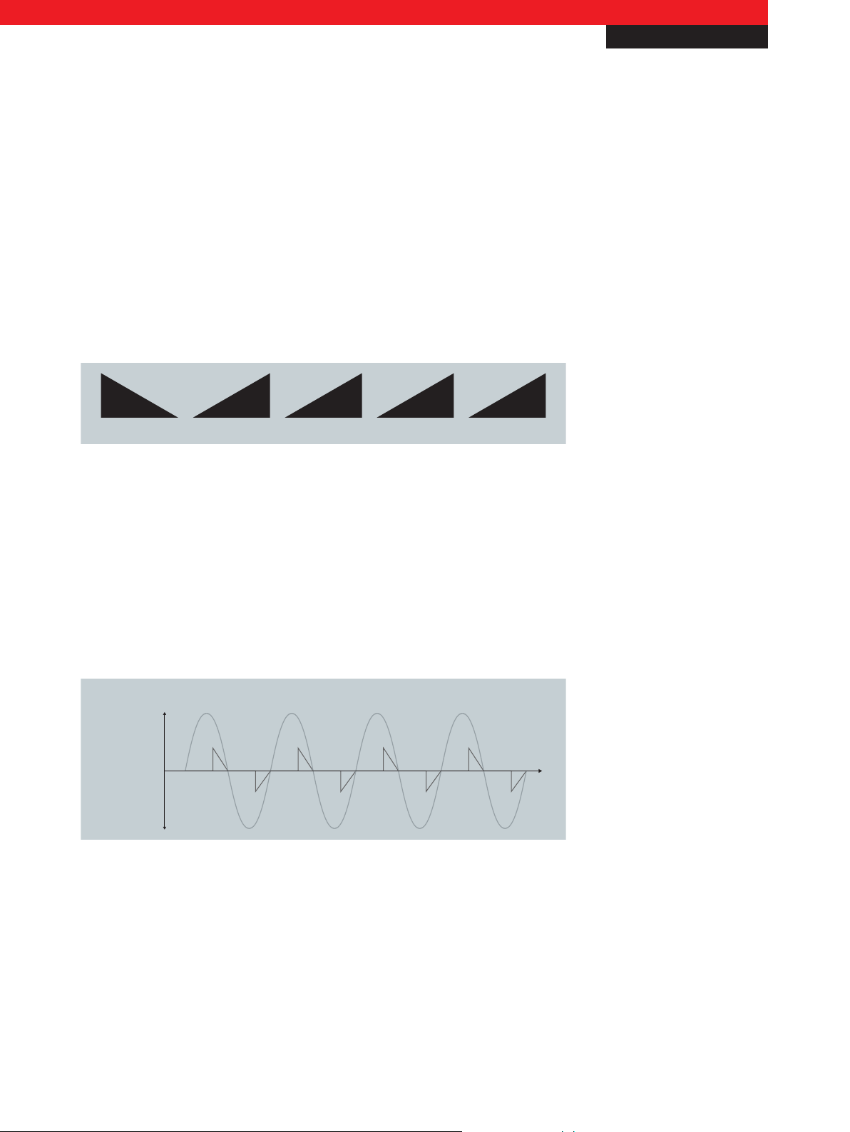
Capacitive and ohmic loads – trailing edge phase control
Trailing edge phase control is used with electronic low-voltage transformers. In the trailing edge phase control technique, the
switch-off point of the switch is changed in relation to the mains voltage half-wave. The current begins to flow exactly at the
zero crossing of the voltage wave; the transistor dimmer terminates the flow of current at a controllable point within the half-
wave. Advantages of this circuit: the flow of current can be interrupted at any time; very accurate control is possible and the
flow of current is also interrupted immediately in the case of an overload or a short-circuit. The generation of current peaks on
input capacitors of the EBs is avoided, since the flat rise of the sine wave is used in order to charge the capacitor. The voltage
For application notes see disclaimer on the last page
Beckhoff
New Automation Technology
2
Page 3

I/O
t
u
i
Trailing edge phase control
Voltage u,
Current i
Application Note DK9222-0310-0010
Bus Terminals
required for the load is approached ‘softly’; this accurate regulation protects the load. Trailing edge phase control dimmers are
provided with a current limiter function, which reduces the output voltage in the case of overload. Furthermore, trailing edge
phase control generates very little electromagnetic interference. Unfortunately, the types of switches used are very sensitive
and are destroyed even by brief overloading. As prevention therefore, complex protective circuits are integrated. 230 V general-
purpose lamps (ohmic loads) and lamps with EBs (capacitive loads) can be used as loads.
Fig. 3 Change of switch-off point with trailing edge phase control
Universal dimmer
Trailing edge phase control cannot be used with capacitive loads, because a sudden increase in voltage would cause an
extremely high current flow. On the other hand, trailing edge phase control is not suitable for inductive loads, because a
voltage peak would occur when switching off the current. If a wire-wound transformer is operated in error with a trailing edge
phase control dimmer, then damage to the power transistor and the protective components of the dimmer is to be expected
due to the resulting inductive voltage peaks. Additionally, damage to the cable insulation and the transformer windings can
occur. If using wire-wound transformers, it is particularly important to ensure a high degree of stability and symmetry in the
leading edge phase control dimmer, in order to prevent the development of direct current components in the primary winding
of the transformers with risks of overheating and cable breakage. In order to avoid this selection problem, universal dimmers
have been developed in which both control principles are implemented. They are particularly advantageous and uncomplicated
to handle, because they automatically recognise the type of load when switching on the connected mains supply and therefore
use the appropriate control principle. However, the electrical behaviour of the connected load must also be uniform in this case.
A further advantage of universal dimmers is that a change of the lighting elements (i.e. a change of the type of load) does not
entail changing the dimmer, because it is suitable for every load (inductive, ohmic and capacitive).
Practical problem: uniform brightness regulation
In practice, the operator expects that a quarter of a turn of the rotary switch of the dimmer will also lead to a change in the
brightness by a quarter. In case of conventional phase controls without integrated characteristic, however, the expected effect
does not occur, since only the switch-on/off point is controlled and not the power. Since the brightness corresponds to the
power, a change of the switching point by 5 % does not result in an actual change in the brightness of 5 %. Depending upon
For application notes see disclaimer on the last page
Beckhoff
New Automation Technology
3
Page 4

I/O
Application Note DK9222-0310-0010
Bus Terminals
the type of control and the point of the output values within the sine half-wave, the actual control effect will be considerably
stronger or weaker.
The visible light corresponds to the power P supplied to the lamp, which, in the case of AC voltage,of the product of the time-
dependent variables î and û. Due to the multiplication of the two variables, the power is also positive in the negative half-
wave. The momentary values î and û have a different value depending on the point in the mains wave, thus their product, the
power P, is also different at different points in the mains wave. Without an integrated characteristic the step width on the time
axis is constant. The power within the constant step width is not constant, since the amount of space below the sine wave
changes per step. The constant step width is particularly disadvantageous when regulating around the peak of the sine wave:
A step width reduction at 50 % by ±10 percentage points corresponds to a brightness adjustment of considerably more than
20 %. Therefore, the operator is inevitably compelled to adjust more precisely in order to achieve a linear change of brightness.
In practice, it is therefore difficult to achieve adjustment with high repeatability. If controlled illumination of the room is
desired, one is compelled by means of commissioning to trace a linearisation characteristic and subsequently to enter it in the
controller by hand accordingly.
Network-capable dimmers with linearised characteristic
The KL2751 and KL2761 Bus Terminals are universal dimmers with linearised characteristic for the uniform brightness
regulation of lighting elements. Capacitive, inductive and ohmic loads can be connected to the single-channel universal
dimmer terminals. Since the terminals are capable of both types of phase control, they can also be used as power switches
for the control of AC loads, depending on the power requirement of the connected load (KL2751: 300 VA, KL2761: 600 VA).
Furthermore, the terminals can be integrated in any control environment via Bus Couplers and are thus among the few
currently available network-capable universal dimmers that are not based on the DMX protocol standard normally used for
professional lighting (as of 09/2009).
The terminals offer many advantages to the user and are particularly uncomplicated to handle. As is typical of universal
dimmers, there is no need to exchange the dimmer if the type of load has changed (R, L, C). The terminal recognises the
connected load automatically after switching on the mains supply (not after switching on the consumer!) and applies the
appropriate control principle. Furthermore, the terminal is short-circuit-proof: Without the employment of a short-circuit-proof
dimmer, the fuse must also be exchanged as a rule when exchanging the lamp, since the fuse is also damaged by the short-
circuit when the filament burns out. The short-circuit resistance of the KL2751/61 prevents damage to the fuse, so that no
maintenance work is necessary inside the control cabinet when exchanging the lamp. The terminal is particularly discrete in
the control cabinet because, with a width of only 12 mm, it takes up the space of two conventional rail mounted terminals, like
almost all Bus Terminals from Beckhoff Automation GmbH. It is thus four times smaller than a conventional universal dimmer
for DIN rail mounting. The dimming behaviour of the KL2751/61 is considerably more consistent than that of the conventional
universal dimmer due to the internal linearisation. As opposed to a constant step width, a brightness-dependent step width is
For application notes see disclaimer on the last page
Beckhoff
New Automation Technology
4
Page 5

I/O
Application Note DK9222-0310-0010
Bus Terminals
selected in the KL2751/61, so that the power increase per step remains constant. A change of the process data by, for example,
27 % also produces a change of brightness of 27 %, independent of the output value.
– 1-channel universal dimmer terminal, 230 V AC, 300 VA (W) www.beckhoff.com/KL2751
– 1-channel universal dimmer terminal, 230 V AC, 600 VA (W) www.beckhoff.com/KL2761
– The modular automation components for building automation www.beckhoff.com/building
This publication contains statements about the suitability of our products for certain areas of application. These statements are based on typical features of our products. The examples shown in this publication are for demonstration purposes only. The information provided herein should not be regarded as specific operation characteristics. It is incumbent on the
customer to check and decide whether a product is suit-able for use in a particular application. We do not give any warranty that the source code which is made available with this
publication is complete or accurate. This publication may be changed at any time with-out prior notice. No liability is assumed for errors and/or omissions. Our products are described
in detail in our data sheets and documentations. Product-specific warnings and cautions must be observed. For the latest version of our data sheets and documentations please visit
our website (www.beckhoff.com).
© Beckhoff Automation GmbH, March 2010
The reproduction, distribution and utilisation of this document as well as the communication of its contents to others without express authorisation is prohibited. Offenders will be
held liable for the payment of damages. All rights reserved in the event of the grant of a patent, utility model or design.
Beckhoff
New Automation Technology
5
 Loading...