

Page 1

I/O
Application Note DK9222-0211-0021
XFC
Keywords
EL1252
EL2212
EL2252
Time stamp
XFC
EtherCAT
Exact system time
eXtreme Fast Control
Process data
Time stamp – a snapshot of control technology
This application example describes how, using the Beckhoff XFC technology, the temporal resolution of
field signals for the controller is made several times more precise and, in addition, the validity of the
process data is released from the PLC cycle. The bases for these characteristics are the fast real-time
fieldbus EtherCAT and the time stamping features of the Beckhoff EL1252 and EL2252 digital input and
output terminals, whose process data contain the exact time specification of an event in addition to the
user data.
Introduction: XFC – eXtreme Fast Control
XFC is a control technology that enables very fast and highly deterministic I/O responses. It includes all hardware and software
components involved in control applications:
– optimized I/Os that can pick up signals with high accuracy or
– EtherCAT as an extremely fast communication network,
– high-performance Industrial PCs as the basis for the control hardware
– TwinCAT, the automation software that links all system components with one another.
Contrary to the original free-running communication links, in which the determinism of the process signals was accordingly
initiate tasks,
inaccurate, the employment of XFC significantly lowers the cycle time and the determinism required for rigorous
real-time demands. XFC enables cycle times of 100 μs without sacrificing the centralized intelligence and its high-performance
algorithms. XFC also includes additional technologies that not only improve cycle times but also temporal accuracy and
resolution. This opens up new possibilities to improve the quality of machines and to shorten reaction times. Measuring tasks,
such as preventive maintenance, the monitoring of life cycles or the documentation of parts quality, can all be integrated
For application notes see disclaimer on the last page
New Automation TechnologyBeckhoff
1
Page 2
I/O
cycle time
task task
synchronous operation of PLC and fieldbus
I/O update per fieldbus
PLC
point
real-time
cycle time used = maximum resolution of an event
time
time
Application Note DK9222-0211-0021
XFC
in a simple manner in a central place in the machine controller without requiring external black boxes. XFC technology is
completely compatible to existing solutions in all areas and can be used simultaneously on the same hardware and software
platform as other control processes such as PLC and motion control, for example.
Validity of process data
Each PLC-based controller works cyclically: it communicates with its environment by receiving input data, processing these on
the basis of the calculation specification (’program’) and then outputting them to the field as output data. Ideally, the fieldbus
cycle can be executed so quickly that refreshed input data are already present at the beginning of the next program cycle.
Depending on the requirements, these cycle times vary between 50 µs to over 100 ms, and are dependent on the fieldbus used
and the performance of the controller. Independent of the PLC cycle time, the cycle time of the fieldbus must also be taken into
account: Not every fieldbus technology available on the market permits synchronous operation of the PLC and fieldbus with
low cycle times, so that a further temporal inaccuracy can also arise here.
Fig. 1 Synchronous operation
Due to this cyclic orientation, however, an event that occurs in reality at a certain, singular point in time can only be assigned
temporally by the PLC in a certain pattern, i.e. the length of the cycle time. If the controller works, for example, with a cycle
time of 10 ms, the edge change at the read-in input actually took place ’sometime’ within the preceding 10 ms before the I/O
update. A more exact assignment than the cycle time resolution of 10 ms is not possible.
Fig. 2 Temporal relation
For application notes see disclaimer on the last page
New Automation TechnologyBeckhoff
2
Page 3

I/O
Reduction of the cycle time for maximized accuracy
PLC cycle time
Demanded
resolution
PLC cycle time
Physical limits of the
fieldbus and the
controller are reached.
Residual demand cannot
be met.
Before
Demanded
nominal
state
Application-wide synchronicity with Distributed Clocks
Application Note DK9222-0211-0021
XFC
If the temporal assignment is to be more precise, only the cycle time can be reduced by using a 1 ms task instead of a 10 ms
one. A temporal classification that is more precise by a factor of 10 is thus possible. This leads to a higher load on the controller
and fieldbus and can impair system stability in the case of overloading. Low performance controllers in particular impose limits
on this approach. As a positive side effect, the possible minimum reaction time of the controller to external events is thereby
shortened, but that is not the main subject of this application example.
Fig. 3 Reduction of the cycle time
Time-stamped process data with an application-wide, uniform timebase
A further approach to the refinement of the temporal resolution is the use of time-stamped process data under EtherCAT with
XFC. The special “Timestamp” XFC terminals for the EtherCAT terminal system from Beckhoff pass not only the event on to the
controller via the fieldbus, but also add a time specification in the form of a time stamp. This time specification can be used in
order to establish the exact temporal relationship between event and reaction inside the controller. The basis for the use of the
time stamp is an application-wide, uniform timebase, which is guaranteed by the EtherCAT Distributed Clock mechanism.
Fig. 4 Application-wide synchronicity
The various segments and devices in an EtherCAT network are synchronized via Distributed Clocks. The micro-delays in the
protocol runtime are calculated and the system times of the individual devices are corrected accordingly. This approach results
For application notes see disclaimer on the last page
New Automation TechnologyBeckhoff
3
Page 4

I/O
time stamp
06.12.10 16.45 pm 36 s 279 ms 123 µs 546 ns
real-time
changing edge at the digital input
Temporal assignment with time stamp
PLC time
EtherCAT
Application Note DK9222-0211-0021
XFC
in the identical system time being present in the entire network. In addition, the controller/PLC is also synchronized, as a result
of which the fieldbus clock with the I/O update is synchronous to the PLC.
The exact temporal assignment of the events takes place on this uniform timebase. The process data no longer consist only
of user data; they additionally have a time stamp containing the concrete time of the event. The time stamp is a 64-bit value
with a resolution of 1 ns, which enables a significantly more detailed temporal reference of the process data and releases the
process information from the PLC cycle. With typical plant sizes, the performance of EtherCAT is so high that signals collected
from the field are available to the controller even before a new computing cycle is started. Hence, a short reaction time is
already possible in the next cycle.
Influence on input signals
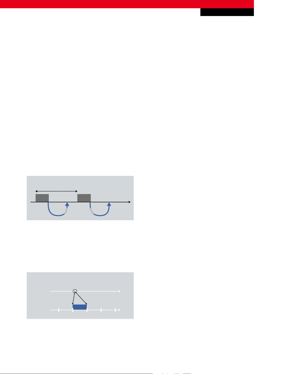
Due to this time stamp principle, event recognition is released from the coarse pattern of the cycle clock and can be resolved
with the much finer pattern of 1 ns without increasing the system load.
Fig. 5 Temporal classification by time stamp
Influence on output signals
The time stamp principle is also used to trigger events, since the identical criteria of the temporal assignment exist here and
the switching of output signals is also released from the rigid pattern of the cycle time. If a digital output is to be activated
at a defined time X, in order to trigger a cutting procedure on a paper web, for example, an appropriate time stamp is set for
the digital output. The time at which the cutter must be activated is calculated from the temporal relationship between the
transport speed of the paper web and the length of the piece to be cut.
For application notes see disclaimer on the last page
New Automation TechnologyBeckhoff
4
Page 5

I/O
Application Note DK9222-0211-0021
XFC
Time stamp terminals from Beckhoff
EL1252 | 2-channel digital input terminal with time stamp
EL2212 | 2-channel digital output terminal 24 V DC with overexcitation
EL2252 | 2-channel digital output terminal with time stamp, tri-state
In addition to the EtherCAT Terminals, Beckhoff also offers all required components for a control solution that enables very fast
and extremely deterministic reactions. XFC includes all hardware and software components involved in control applications:
optimized input and output components that can pick up signals with high accuracy or initiate tasks, EtherCAT as the very
fast communication network, high-performance Industrial PCs and TwinCAT, the automation software that links all system
components.
Practical example | simultaneity
Without the use of a time stamp, it is not possible from the point of view of the CPU to distinguish changes of a signal within a
fieldbus cycle or to classify them with a temporal accuracy greater than the time pattern dictated by the fieldbus. Therefore, the
simultaneity of events cannot be adequately judged. Thus in fault finding, for example, the time stamps from the various field
devices can be compared with one another in order to differentiate the causes of consequential errors.
Practical example | reference signals in test setups and test benches
External high precision clocks, for example the atomic clock of the Physikalisch-Technische Bundesanstalt (Federal Institute
of Physics and Metrology) in Braunschweig (Brunswick), Germany, are often used to provide the test setup of a device with a
reliable and constant timebase that is valid as a reference measured variable in different series of tests. For simple integration
via decentralized I/Os, the time signal is laid as a clock on a digital input terminal with time stamp, e.g. the EL1252 EtherCAT
Terminal. Since the EtherCAT Terminals work with the high bandwidth of 100 Mbit/s right into the terminals, the controller of
the test setup can fall back on the fed-in time signal and place all events within the system in exact relationship to one another
by the Distributed Clocks function. The deterministics arising from this are identical for all measurement series and allow
concrete conclusions to be drawn between two different series of measurements.
For application notes see disclaimer on the last page
f
New Automation TechnologyBeckhof
5
Page 6

I/O
Application Note DK9222-0211-0021
XFC
Apart from the time-constant measurement of events by the time-stamped process data, actions are also executed at a
precisely defined time. Thus, parallel wired peripherals can be eliminated on test and experimental benches by means of not
initiating an action directly by a user intervention, but rather by the user ‘announcing’ it at an exactly defined process data
point/time.
The described relations are decisive for test benches in which a volume throughput per unit time is measured.
External reference time
Calibration to ext. reference
PLC
EL1252
Reference
Device
under
Measured value
Test
Fig. 6 Practical time stamp example: calibration to an external reference
– 2-channel digital input terminal with time stamp www.beckhoff.com/EL1252
– 2-channel digital output terminal 24 V DC with overexcitation www.beckhoff.com/EL2212
– 2-channel digital output terminal with time stamp, tri-state www.beckhoff.com/EL2252
– XFC: The new class of Control Performance www.beckhoff.com/XFC
– EtherCAT www.beckhoff.com/EtherCAT
This publication contains statements about the suitability of our products for certain areas of application. These statements are based on typical features of our products. The examples shown in this publication are for demonstration purposes only. The information provided herein should not be regarded as specific operation characteristics. It is incumbent on the
customer to check and decide whether a product is suit-able for use in a particular application. We do not give any warranty that the source code which is made available with this
publication is complete or accurate. This publication may be changed at any time with-out prior notice. No liability is assumed for errors and/or omissions. Our products are described
in detail in our data sheets and documentations. Product-specific warnings and cautions must be observed. For the latest version of our data sheets and documentations please visit
our website (www.beckhoff.com).
© Beckhoff Automation GmbH, February 2011
The reproduction, distribution and utilisation of this document as well as the communication of its contents to others without express authorisation is prohibited. Offenders will be
held liable for the payment of damages. All rights reserved in the event of the grant of a patent, utility model or design.
New Automation TechnologyBeckhoff
6
 Loading...