

Page 1

I/O
Application Note DK9222-0112-0059
Measuring analog signals
Keywords
Loop-powered
2-wire transmitter
True Zero
4-20 mA
KL3458
Analog
Single-ended
Current loop
Loop power
Live Zero
KL3454
KL3054
Difference
Input
Analog signal transmission: Current interface 4…20 mA
(Live Zero principle)
This application example describes the facets of analog signal recording and their forms of transmission in
general. In particular, this document covers the recording of measured values using the KL3054, KL3454 and
KL3458 analog input Bus Terminals from Beckhoff. When used in conjunction with 2 or 3-wire sensors, these
terminals enable the detection of cable breakage and sensor failures internally in the circuit according to
the Live Zero principle.
Analog signal recording
Analog measured variables such as pressure, temperature, flow, speed, etc. are converted by sensors into analog values and,
depending on the sensor, are also linearized inside the sensor. Sensors for analog measured variables usually consist of two
functional elements – the measuring sensor and the transducer – and determine the change in the measured variable by
means of a physical principle. The digitized analog signal transmitted to the controller normally corresponds to a standardized
level and is always composed of the type (voltage, current, resistance, etc.) and the value (0 – 10 V, ± 1 V, 0 – 20 mA, 500 mΩ,
etc.)
For application notes see disclaimer on the last page
New Automation TechnologyBeckhoff
1
Page 2
Application Note DK9222-0112-0059
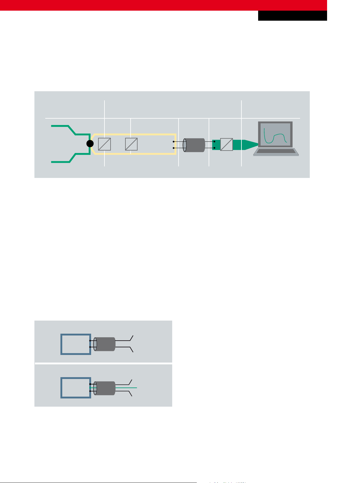
Process
Sensor
Physical quantity
Digital variable
Process data format
Measured
value
Analog
value
Analog
standard signal
Signal
transmission
Analog
input
Control
2-wire sensor
3-wire sensor
sensor
signal
GND
U
B
sensor
signal -
signal +
Measuring analog signals
Fig. 1 The path of an analog process value: from the field into the controller
I/O
In control technology, a sensor can also contain further functional elements (bus connection, integrated scaling of the
measured value, pattern recognition, etc.). It is then usually called a “smart” sensor.
Types of analog sensor connections
Sensors that directly connect to the analog inputs of the controller (‘classic analog sensors’) can be manufactured with a 4-, 3-
or 2-wire configuration, depending on the power supply concept and signal transmission method.
4-wire sensors conduct signal and power each via two wires. The wiring expenditure is high with this type of connection.
3-wire sensors use two wires for the power supply and output the signal via a separate wire. The reference potential is the
GND wire.
2-wire sensors conduct the signal and power supply via one (common) supply wire. The 2-wire technique requires little wiring
expenditure and represents the state of the art in measuring transducers for field and sensor head mounting.
For application notes see disclaimer on the last page
Fig. 2 2-wire sensor with power and signal on one wire, 3-wire sensor with separate wires for power and signal
Methods of transmission of analog process values
In control technology the signal levels for the transmission of the sensor signals are standardized in order to ensure the
most extensive compatibility of sensors and evaluation units possible, without restricting the level of freedom in product
New Automation TechnologyBeckhoff
2
Page 3

I/O
Voltage Current
Types of analog signals
±2 V, ±10 V –bipolar
0…20 mA
0…2 V, 0…10 Vtrue zero
1…10 V 4…20 mA
live zero
+
–
0
+
0
+
0
Application Note DK9222-0112-0059
Measuring analog signals
development. Voltage or current-based methods of transmission are mainly used (table 1). In the transmission of analog
process values, one must also keep in mind that the digitalized signal has a tendency to dither as the resolution increases
(the more finely it represents the process value). If a high-resolution signal is demanded, the transmission must be free from
superimposed interference. Current-based transmission via so-called “current interfaces” is particularly recommended for such
applications. In comparison with voltage signals they are significantly less sensitive to electromagnetic interference. In general
it can be concluded that, in the case of current interfaces, power-related voltage drops (resulting from the internal resistance
of the supply line) hardly affect the quality of the signal transmission if at all: The length of the cable is limited only by the
maximum available supply voltage of the power source.
Tab. 1 Types of analog signals
Bipolar signals
Bipolar signals alternate around a voltage or current level that is usually 0 (“zero”). Depending on the application and the
specification of the sensor, an offset can be applied to the level. With this type of signal it must be ensured that the sensor
and the evaluation electronics are also suitable for AC voltages. The current-based transmission of bipolar signals is not very
common.
True Zero (0…2/10 V | 0…20 mA)
This type of signal is only conditionally suitable for transmission via 2-wire connections, since signals with the classification
“True Zero” always require external auxiliary power at the start of the measuring range so that the sensor remains “viable.” In
addition, a wire breakage or sensor failure can be detected reliably only with external monitoring.
The adequate detection of a wire breakage or a sensor defect is problematic because the value “0” can be interpreted both as
the end value of the measuring range and as an error. In practice, therefore, an additional external sensor monitor is frequently
used.
For application notes see disclaimer on the last page
New Automation TechnologyBeckhoff
3
Page 4

I/O
Bus Terminals for the evaluation of current-based analog signals (KL3xxx | KS3xxx)
8-channel
True Zero
Live Zero
KL3448 | KS3448
8 x 1-wireconnection, 12 bit
KL3458 | KS3458
8 x 1-wireconnection, 12 bit
1-channel
KL3011 | KS3011
Differential input,
12 bit
KL3041 | KS3041
loop-powered,
12 bit
KL3021 | KS3021
Differential input,
12 bit
KL3051 | KS3051
loop-powered,
12 bit
4-channel
KL3444 | KS3444
4 x 2-wireconnection, 12 bit
KL3044 | KS3044
12 bit
KL3454 | KS3454
4 x 2-wireconnection, 12 bit
KL3054 | KS3054
12 bit
2-channel
KL3012 | KS3012
Differential input,
12 bit
KL3042 | KS3042
loop-powered,
12 bit
KL3112 | KS3112
Differential input,
16 bit
KL3142 | KS3142
16 bit, 0,05%
KL3022 | KS3022
Differential input,
12 bit
KL3052 | KS3052
loop-powered,
12 bit
KL3122 | KS3122
Differential input,
16 bit
0 ... 20 mA
4 ... 20 mA
+
0
+
0
Application Note DK9222-0112-0059
Measuring analog signals
Live Zero (1/2…10 V | 4…20 mA)
Since a finite value (value > 0) of the lower measuring range (1/2 V, 4 mA) enables the permanent supply of power to the
sensor or the internal circuit without an external supply, internal monitoring (sensor defect/wire breakage) can also be realized
in this way. Signals with the classification “Live Zero” are typical for 2-wire sensors with high availability checking. The
Live Zero circuit is also advantageous for fault-finding: The signal curve can be measured with a multimeter over the entire
transmission link.
Note:
The Beckhoff products described below are not to be assigned to the HART classification. They are neither “HART-compatible”
nor are they suitable for use as intrinsically safe equipment in explosive zones.
The Beckhoff analog Bus Terminals | Evaluation units for analog signals
For the evaluation of analog sensor signals, Beckhoff offers an extensive range of Bus Terminals from the KL3xxx series, which
cover a broad range of applications in analog signal processing. The input circuit of the Bus Terminals differs between single-
ended and differential inputs. A single-ended input expects a signal with a fixed reference to ground.
Tab. 2 Bus Terminals for the evaluation of current-based analog signals
For application notes see disclaimer on the last page
New Automation TechnologyBeckhoff
4
Page 5

Application Note DK9222-0112-0059
Bus Terminals for Live Zero signals 4…20 mA
Integrated
voltage supply
Number of channels
Resolution
Reference ground
Connection example
Sensor supply
Optional power
feed terminal
KL3454
yes/24 V DC
4
12 bit
0 V power contact
2-wire sensor
loop-powered
–
KL3454
sensor
KL3054
no
4
12 bit
common reference
ground of all 4 inputs
2/3-wire sensor
external; terminal
as galvanic island
–
KL3054
sensor
+U
B
KL3458
no
8
12 bit
0 V power contact
3-wire sensor 2-wire sensor
KL9184 KL9186
8 x 24 V DC
8 x ground
8 x 24 V DC
KL3058
sensor
+U
B
U
B
KL3058
sensor
+U
B
Measuring analog signals
I/O
Tab. 3 The measuring error of all 4 – 20 mA Bus Terminals is < ± 0.3% (in relation to the full scale value).
KL3454 | Loop-powered 2-wire sensors (“loop powered”, Live Zero)
The KL3454 4-channel analog input Bus Terminal supports the direct connection of 2-wire sensors without an external power
supply. The sensors are supplied with power directly via the evaluation unit – they are “loop-powered.” An external voltage
supply can be omitted, since the 24 V power contact is fed to the terminal points. The KL3454 digitizes current signals within
the range of 4 to 20 mA with a maximum resolution of 12 bits. The internal wiring of the KL3454 has such a low impedance
that even if the sensor reaches full scale (signal level 20 mA) the low voltage drop inside the terminal can still provide the
sensor with sufficient power. The resistance of the internal wiring (80 Ω) and the length-dependent wire resistance add up
to a total that lies significantly below the otherwise usual 500 Ω. Therefore, it is usually not necessary to impose a maximum
permissible cable length.
KL3054 4-channel analog input Bus Terminal
The KL3054 also supports the connection of sensors for 4 – 20 mA signals using the 2-wire configuration. Exclusively
externally-powered sensors may be connected, i.e. they must be supplied externally with power, since the Bus Terminal
functions as a galvanic island. Using the KL3054, analog values can be determined with different sensor supply voltages or
between components that have no common ground connection. Like the KL3454, the KL3054 digitizes the sensor signals with
12 bits.
For application notes see disclaimer on the last page
New Automation TechnologyBeckhoff
5
Page 6

I/O
1-wire connection of externally-powered sensors via KL3458:
common reference potential
Necessary coupling between GND and 0 V power contact
K-Bus power supply
0 V power contact
KL3458
arbitrary
fieldbus connection
+ 24 V
GND
sensor A sensor B
Application Note DK9222-0112-0059
Measuring analog signals
KL3458 8-channel analog input Bus Terminal
The KL3458 unites eight inputs in a single housing, offering the possibility to connect multi-channel sensors using single-wire
technology in a minimal amount of space. The KL3458 is suitable for externally-powered 2 and 3-wire sensors, but a connection
must be made in each case between the ground of the sensor power supply and that of the Bus Terminal node (0 V power
contact).
Fig. 4 KL3458 connection example: for the single-wire connection of externally-powered sensors, it is necessary to couple the GND
(sensor power supply) to the 0 V power contact of the terminal node.
Bus Terminals for Live Zero signals – “differential input”
Despite the advantages in signal transmission, the connection of sensors via a current loop also has disadvantages: unlike
with voltage-based signals, consumers cannot be connected in parallel with each other. If a measured value is to be processed
in several places, a series connection of the evaluation units is necessary. Only one evaluation unit with a ground reference
can work in this series connection, all others require a differential input that does not expect a common connection of the
individual grounds.
Such a series connection is created, for example, if a measured value is not to be transmitted exclusively to the controller,
but is to be visualized via a display device (a digital ammeter installed in the control cabinet) without the intervention of
the controller. In such cases measurement via an analog differential input that does not expect a common connection of the
individual ground connections should be used.
For application notes see disclaimer on the last page
New Automation TechnologyBeckhoff
6
Page 7

Application Note DK9222-0112-0059
Correct multiple tapping of a current-based measured value
A
=
KL3022
differential
input
KL3xxx
Single-
ended
4…20 mA
Measuring analog signals
Fig. 5 Series connection of differential and single-ended inputs for the multiple tapping of a current-based measured value
I/O
Worth knowing
HART protocol
The HART communication (Highway Addressable Remote Transducer) also uses analog 4 – 20 mA technology in conjunction
with 2-wire sensors. HART describes remotely addressable transducers and is a function-oriented extension of the analog
current signal by the simultaneous superimposition of digital information. HART is typically used in the process industry where
it is frequently implemented in explosive zones, among other areas.
Systematic measuring error with user-specific scaling
4 mA are always needed for the sensor supply, as a result, the hub of 16 mA represents the process data information that must
be evaluated by the evaluation unit. Typical errors frequently result from an incorrectly adapted user scaling, which does not
map the zero point correctly.
High-energy overvoltage
For applications in which high-energy overvoltages are to be expected on the supply voltage, analog signals can be additionally
screened by the employment of a KL9540-0010 surge filter terminal from Beckhoff.
– Bus Terminals for analoge input signals www.beckhoff.com/KL3xxx
– Surge filter field supply for analog terminals www.beckhoff.com/KL9540-0010
– Potential distribution (0V | 24 V ) for eight 3-wire sensors www.beckhoff.com/KL9184
– Potential distribution (24 V ) for eight 2-wire sensors www.beckhoff
– Modular fieldbus system for automation www.beckhoff.com/Busterminal
For application notes see disclaimer on the last page
.com/KL9186
f
New Automation TechnologyBeckhof
7
Page 8

Application Note DK9222-0112-0059
Measuring analog signals
I/O
This publication contains statements about the suitability of our products for certain areas of application. These statements are based on typical features of our products. The examples shown in this publication are for demonstration purposes only. The information provided herein should not be regarded as specific operation characteristics. It is incumbent on the
customer to check and decide whether a product is suit-able for use in a particular application. We do not give any warranty that the source code which is made available with this
publication is complete or accurate. This publication may be changed at any time with-out prior notice. No liability is assumed for errors and/or omissions. Our products are described
in detail in our data sheets and documentations. Product-specific warnings and cautions must be observed. For the latest version of our data sheets and documentations please visit
our website (www.beckhoff.com).
© Beckhoff Automation GmbH, January 2012
The reproduction, distribution and utilisation of this document as well as the communication of its contents to others without express authorisation is prohibited. Offenders will be
held liable for the payment of damages. All rights reserved in the event of the grant of a patent, utility model or design.
New Automation TechnologyBeckhoff
8
 Loading...