

Page 1
Hardware Documentation
CX9000 / CX9010
Ebedded-PC
2.6
2015-07-10
Version:
Date:
Page 2

Page 3

Table of contents
CX9000 / CX9010 3Version: 2.6
Table of contents
1 Foreword ....................................................................................................................................................5
1.1 Notes on the documentation........................................................................................................... 5
1.2 Safety instructions .......................................................................................................................... 6
1.3 Documentation Issue Status........................................................................................................... 7
2 Product overview.......................................................................................................................................8
2.1 Appropriate Use.............................................................................................................................. 8
2.2 Ethernet-Controller CX90x0............................................................................................................ 9
2.3 Basic modules .............................................................................................................................. 10
2.3.1 Technical data..................................................................................................................11
2.3.2 Technical data..................................................................................................................12
2.3.3 Technical data..................................................................................................................13
2.3.4 Technical data..................................................................................................................14
2.3.5 Configurations..................................................................................................................15
2.3.6 Configurations..................................................................................................................16
2.3.7 Connections .....................................................................................................................17
2.3.8 Battery compartment........................................................................................................20
2.3.9 CX90x0 : Dip switch settings ...........................................................................................21
2.4 System interfaces ......................................................................................................................... 23
2.4.1 Technical Data .................................................................................................................23
2.4.2 CX90x0-N010 connections ..............................................................................................24
2.4.3 CX90x0-N030 connections ..............................................................................................26
2.4.4 CX90x0-N031 connections ..............................................................................................27
3 Transport..................................................................................................................................................30
3.1 Unpacking, installation and transport............................................................................................ 30
4 Assembly and connecting ......................................................................................................................31
4.1 Mechanical assembly ................................................................................................................... 31
4.1.1 Dimensions ......................................................................................................................31
4.1.2 Mechanical assembly of the basic module ......................................................................33
4.1.3 Mechanical installation of the UPS Module......................................................................34
4.2 Start-up procedure........................................................................................................................ 37
4.2.1 Switching the PC on and off.............................................................................................37
5 Error handling and diagnostics .............................................................................................................38
5.1 CPU basic module ........................................................................................................................ 38
5.1.1 LEDs Basic CPU-module (E-Bus)....................................................................................38
5.1.2 LEDs Basic CPU-module (K-Bus)....................................................................................38
5.1.3 Terminal Bus Analysis in PLC-Program...........................................................................40
6 Decomissioning.......................................................................................................................................42
6.1 Removal and disposal .................................................................................................................. 42
7 Appendix ..................................................................................................................................................44
7.1 CX90x0 : Update Image ............................................................................................................... 44
7.2 Accessories .................................................................................................................................. 57
7.3 Certifications ................................................................................................................................. 59
7.4 Support and Service ..................................................................................................................... 60
Page 4

Table of contents
CX9000 / CX90104 Version: 2.6
Page 5

Foreword
CX9000 / CX9010 5Version: 2.6
1 Foreword
1.1 Notes on the documentation
This description is only intended for the use of trained specialists in control and automation engineering who
are familiar with the applicable national standards.
It is essential that the documentation and the following notes and explanations are followed when installing
and commissioning the components.
It is the duty of the technical personnel to use the documentation published at the respective time of each
installation and commissioning.
The responsible staff must ensure that the application or use of the products described satisfy all the
requirements for safety, including all the relevant laws, regulations, guidelines and standards.
Disclaimer
The documentation has been prepared with care. The products described are, however, constantly under
development.
We reserve the right to revise and change the documentation at any time and without prior announcement.
No claims for the modification of products that have already been supplied may be made on the basis of the
data, diagrams and descriptions in this documentation.
Trademarks
Beckhoff®, TwinCAT®, EtherCAT®, Safety over EtherCAT®, TwinSAFE®, XFC® and XTS® are registered
trademarks of and licensed by Beckhoff Automation GmbH.
Other designations used in this publication may be trademarks whose use by third parties for their own
purposes could violate the rights of the owners.
Patent Pending
The EtherCAT Technology is covered, including but not limited to the following patent applications and
patents:
EP1590927, EP1789857, DE102004044764, DE102007017835
with corresponding applications or registrations in various other countries.
The TwinCAT Technology is covered, including but not limited to the following patent applications and
patents:
EP0851348, US6167425 with corresponding applications or registrations in various other countries.
EtherCAT® is registered trademark and patented technology, licensed by Beckhoff Automation GmbH,
Germany
Copyright
© Beckhoff Automation GmbH & Co. KG, Germany.
The reproduction, distribution and utilization of this document as well as the communication of its contents to
others without express authorization are prohibited.
Offenders will be held liable for the payment of damages. All rights reserved in the event of the grant of a
patent, utility model or design.
Page 6
Foreword
CX9000 / CX90106 Version: 2.6
1.2 Safety instructions
Safety regulations
Please note the following safety instructions and explanations!
Product-specific safety instructions can be found on following pages or in the areas mounting, wiring,
commissioning etc.
Exclusion of liability
All the components are supplied in particular hardware and software configurations appropriate for the
application. Modifications to hardware or software configurations other than those described in the
documentation are not permitted, and nullify the liability of Beckhoff Automation GmbH & Co. KG.
Personnel qualification
This description is only intended for trained specialists in control, automation and drive engineering who are
familiar with the applicable national standards.
Description of symbols
In this documentation the following symbols are used with an accompanying safety instruction or note. The
safety instructions must be read carefully and followed without fail!
DANGER
Serious risk of injury!
Failure to follow the safety instructions associated with this symbol directly endangers the
life and health of persons.
WARNING
Risk of injury!
Failure to follow the safety instructions associated with this symbol endangers the life and
health of persons.
CAUTION
Personal injuries!
Failure to follow the safety instructions associated with this symbol can lead to injuries to
persons.
Attention
Damage to the environment or devices
Failure to follow the instructions associated with this symbol can lead to damage to the environment or equipment.
Note
Tip or pointer
This symbol indicates information that contributes to better understanding.
Page 7

Foreword
CX9000 / CX9010 7Version: 2.6
1.3 Documentation Issue Status
Version Changes
2.6 annotations to battery recycling added
2.5 notes on image update renewed
2.4 system interfaces CX1200-xxxx removed
2.3 new installation positions are added
2.2 changes in names of system interfaces CX90x0N070 and CX90x0-N080 inserted
2.1 notes on new system interfaces CX90x0-N070 and
CX90x0-N080 added
2.0 notes on CX9010 added, notes on battery usage and
update procedure changed
1.9 order information changed
1.8 notes on K-Bus diagnosis added
1.7 notes on USV and CF card handling added title
picture changed
1.6 notes on image update via software added
1.5 cable length of DVI cable corrected,
1.4 consumption value for CX9000-A001 added
1.3 notes on dip switches and image update added
1.2 notes for CF-card added, errors in module numbers
corrected
1.1 notes for system interface N010 added
1.0 revised version
0.0.1 preliminarily version
Page 8
Product overview
CX9000 / CX90108 Version: 2.6
2 Product overview
2.1 Appropriate Use
The CX-System device series is a modular control system designed for top-hat rail installation. The system is
scalable, so that the required modules can be assembled and installed in the control cabinet or terminal box
as required.
Only switch the PC off after closing the software
Before the Embedded PC is switched off, the software currently running on it should be stopped properly in
order to avoid data loss on the hard disk. Please read the section on “Switching off [}37]”.
Switch off all system components and uncouple the Industrial PC from the system if the PC is not used for
control purposes, e.g. during a function test.
System components that have been switched off must be secured against being switched on again.
The power supply unit of the Embedded PC requires a 24 V DC supply.
DANGER
Parts under power
Do not exchange any parts when under power! When components are being fitted or removed, the supply voltage must be switched off.
Software knowledge
Attention
System malfunctions
Mandatory software knowledge! Every user must be familiar with any of the functions of the
software installed on the PC that he can reach.
Page 9

Product overview
CX9000 / CX9010 9Version: 2.6
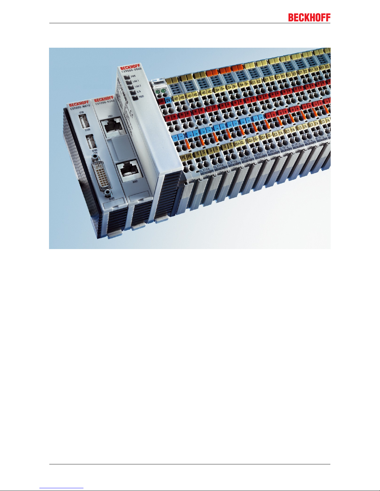
2.2 Ethernet-Controller CX90x0
With the Ethernet controller CX9000, Beckhoff presents a further extension of the family of CX-type
embedded controllers. The CX90x0 is a compact, high-performance yet cost-effective PLC and motion
controller for 30 mm DIN rail mounting. Within the Beckhoff control world it is positioned between the Bus
Terminal Controller series BX and the Embedded PC CX1000. The main feature of this devices is an energysaving 266 MHz or 533 MHz Intel® IXP420 CPU with XScale® technology that runs under the Microsoft
Windows CE operating system. It thus offers adequate computing capacity even for complex automation
tasks. The CX90x0 requires no external storage media – the device boots the operating system from the
internal fl ash. Due to the low power consumption, within the specified operating range no fan is required.
The CX90x0 therefore requires no rotating components. As usual for the CX series, the device features a
modular mechanical design. In its basic configuration, the compact device only measures 58 x 100 x 91 mm.
EtherCAT as fast I/O-System / K-Bus as alternative I/O-System
The CX90x0 is available in two versions: with K-bus for direct connection of Bus Terminals, and as an E-bus
version for direct connection of EtherCAT Terminals. In the basic confi guration, two RJ 45 sockets that are
internally connected to an integrated switch are available as interfaces. This simplifies wiring of several
CX90x0 within a line topology. No separate switch hardware is required. The two externally accessible
Ethernet ports are independent of the EtherCAT interface, which is served by a second MAC (media access
controller) provided by the CPU.
Basic module and Systeminterfaces
Further interfaces may be added ex works as required: A screen display can be realized using a CX90x0N001 device, i.e. a module combining DVI/ VGA + 2 x USB 2.0. The combination of DVI and USB enables all
types of Beckhoff Control Panel with DVI/USB interface to be used. Touch functionality is connected via
USB. As a further option, two RS232 modules or two RS422/RS485 modules can be configured as COM1
and COM2. All serial interfaces feature opto-decoupling. Mass storage in form of a Compact Flash card can
be used via the CX90x0-A000 module, which offers physical storage capacity in the range of several
gigabytes.
SPS, Motion Control and Visualization
Like for all Beckhoff controllers, TwinCAT is used for programming the CX90x0 as an automation device.
The device itself contains the run-time environment for PLC and Motion Control. One of the two Ethernet
interfaces is used as programming interface.
Software
Microsoft Windows CE enables the creation of fully graphic user programs, which are able to satisfy high
expectations thanks to the graphics chip integrated in the CX90x0.
In summary, the CX90x0 is a compact Ethernet controller, which in combination with EtherCAT I/O allows
very fast I/O control cycles. Windows CE and TwinCAT CE constitute the powerful software architecture for
this controller.
Page 10
Product overview
CX9000 / CX901010 Version: 2.6
2.3 Basic modules
The CX90xx is a compact, top hat rail-mountable Ethernet Controller with direct connection to the Beckhoff I/
O systems in IP 20. The CX90xx is available in two basic versions: one version for Bus Terminals with Kbus, the other one for EtherCAT Terminals with E-bus. The CX9000 comprises the CPU, the internal flash
memory with two configuration options, the main memory (RAM) (available in two different sizes), and
NOVRAM as non-volatile memory. In opposite to the CX9000 the CX9010 is only available with 32 MB flash
memory, 128 MB main memory (RAM). Two Ethernet RJ 45 interfaces are also part of the basic
configuration.
These interfaces are connected to an internal switch and offer a simple option for creating a line topology
without the need for additional Ethernet switches. A memory medium in Compact Flash format I and II is
available as an optional module (only in combination with system interface CX9010-N010). The operating
system is Microsoft Windows CE. The TwinCAT automation software transforms a CX90xx system into
powerful PLC and Motion Control system that can be operated with or without visualization.
Further system interfaces can be connected to the CPU module ex works. The CX90xx-N010 option can be
connected to Beckhoff Control Panels or standard monitors with DVI or VGA input via the DVI and USB
interfaces. Devices such as printer, scanner, mouse, keyboard, mass storage, CR-RW etc. can be
connected via the USB2.0 interfaces. The module CX90xx-N030 offers two serial RS232 interfaces with a
maximum transfer speed of 115 kbaud. These two interfaces can be implemented as RS422/RS485, in
which case they are identified as CX90xx-N031.
Page 11
Product overview
CX9000 / CX9010 11Version: 2.6
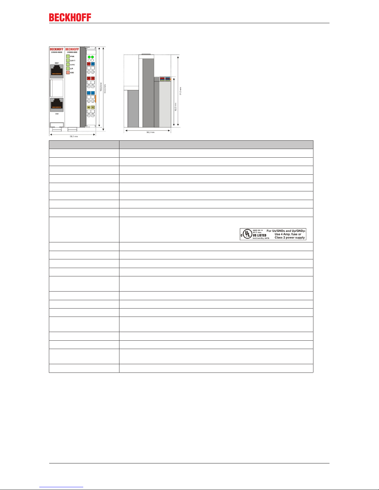
2.3.1 Technical data
Technical data CX9000-0000
Processor Intel® IXP420 with XScale® Technology, 266-MHz clock rate
Internal flash memory 16 MByte Flash (internal, expandable up to 32 MByte)
Internal main memory 64 MByte RAM (internal, expandable up to 128 MByte)
interfaces 2 x RJ 45 (internal Switch), 10/100 MBit
Diagnostics LEDs 1 x Power, 2 x LAN, 1 x L/A, 1 x flash access
Clock internal battery-backed clock for time and date
Operating system Microsoft Windows CE
Control software TwinCAT-CE-PLC-Runtime or TwinCAT-CE-NC-PTP-Runtime
Power supply 24 VDC (-15%/+20%) To meet the UL requirements use a 4 A fuse or a
power supply that has to satisfy NEC class 2!
Dielectric strength 500 V
rms
(supply/internal electronics)
I/O connection E-bus (EtherCAT Terminals)
NOVRAM 128 kByte
I/O-DPRAM -
Power supply I/O
terminals
2 A
Max. power loss 6 W (including CX9000-xxxx system interfaces)
Dimensions (W x H x D) 59 mm x 100 mm x 91 mm
weight ca. 250 g
Operating / storage
temperature
0° C ... +50° C / -25° C ... +85° C
Relative humidity 95% no condensation
Vibration/shock resistance conforms to EN 60068-2-6 / EN 60068-2-27/29
EMC resistance burst/
ESD
conforms to EN 61000-6-2/EN 61000-6-4
Protection class IP 20
Page 12
Product overview
CX9000 / CX901012 Version: 2.6
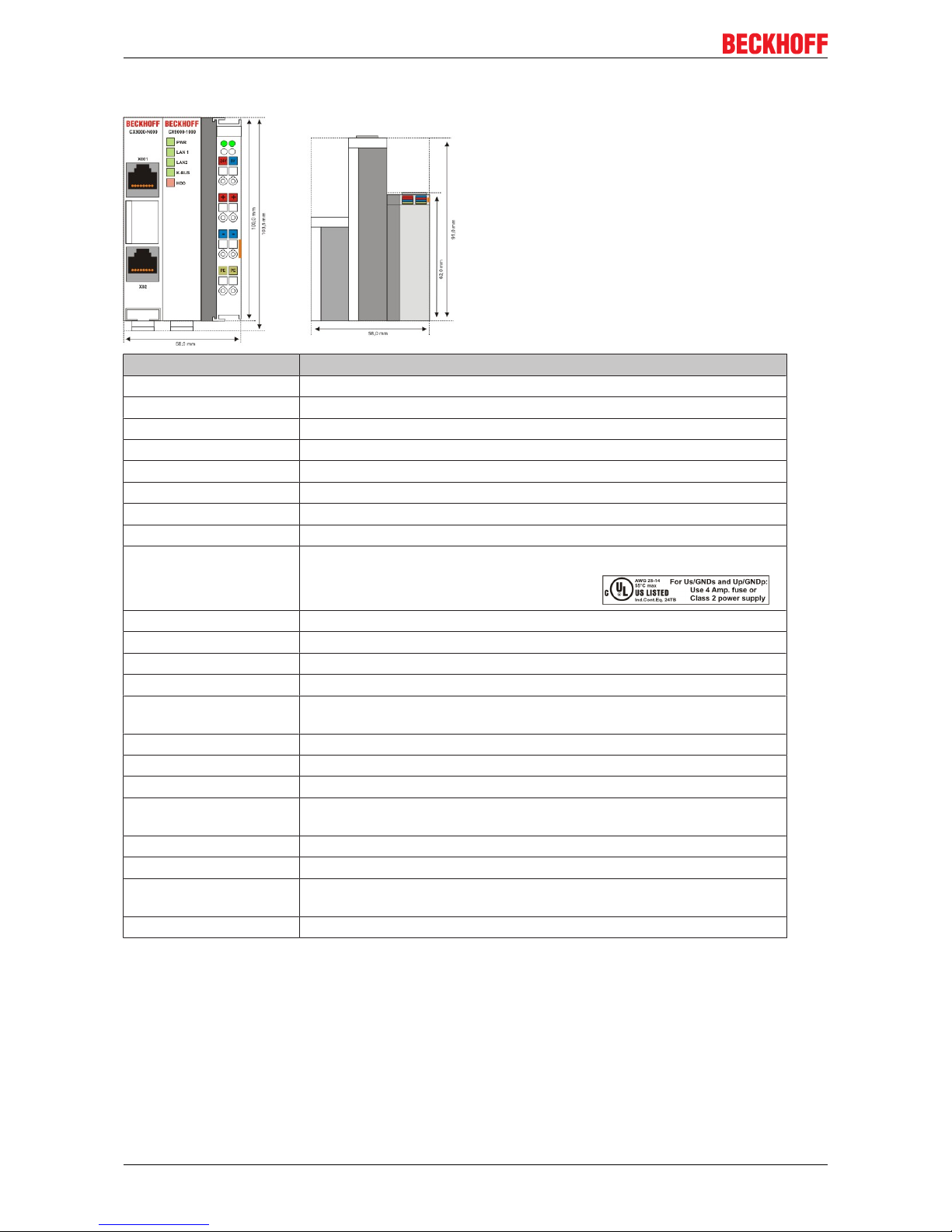
2.3.2 Technical data
Technical data CX9000-1000
Processor Intel® IXP420 with XScale® Technology, 266-MHz clock rate
Internal flash memory 16 MByte Flash (internal, expandable up to 32 MByte)
Internal main memory 64 MByte RAM (internal, expandable up to 128 MByte)
interfaces 2 x RJ 45 (internal Switch), 10/100 MBit
Diagnostics LEDs 1 x Power, 2 x LAN, 1 x K-Bus, 1 x Flash-Zugriff
Clock internal battery-backed clock for time and date
Operating system Microsoft Windows CE
Control software TwinCAT-CE-PLC-Runtime or TwinCAT-CE-NC-PTP-Runtime
Power supply 24 VDC (-15%/+20%) To meet the UL requirements use a 4 A fuse or a
power supply that has to satisfy NEC class 2!
Dielectric strength 500 V
rms
(supply/internal electronics)
I/O connection K-bus (Bus Terminals)
NOVRAM 128 kByte
I/O-DPRAM 4 kByte
Power supply I/O
terminals
2 A
Max. power loss 6 W (including CX9000-xxxx system interfaces)
Dimensions (W x H x D) 59 mm x 100 mm x 91 mm
weight ca. 250 g
Operating / storage
temperature
0° C ... +50° C / -25° C ... +85° C
Relative humidity 95% no condensation
Vibration/shock resistance conforms to EN 60068-2-6 / EN 60068-2-27/29
EMC resistance burst/
ESD
conforms to EN 61000-6-2/EN 61000-6-4
Protection class IP 20
Page 13
Product overview
CX9000 / CX9010 13Version: 2.6
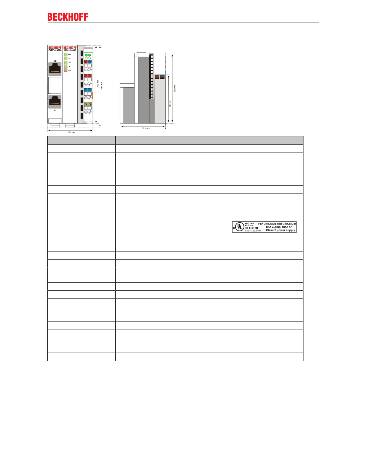
2.3.3 Technical data
Technical data CX9010-0000
Processor Intel® IXP420 with XScale® Technology, 533-MHz clock rate
Internal flash memory 32 MByte Flash (internal)
Internal main memory 128 MByte RAM (internal)
interfaces 2 x RJ 45 (internal Switch), 10/100 MBit
Diagnostics LEDs 1 x Power, 2 x LAN, 1 x L/A, 1 x flash access
Clock internal battery-backed clock for time and date
Operating system Microsoft Windows CE
Control software TwinCAT-CE-PLC-Runtime or TwinCAT-CE-NC-PTP-Runtime
Power supply 24 VDC (-15%/+20%) To meet the UL requirements use a 4 A fuse or a
power supply that has to satisfy NEC class 2!
Dielectric strength 500 V
rms
(supply/internal electronics)
I/O connection E-bus (EtherCAT Terminals)
NOVRAM 128 kByte
I/O-DPRAM -
Power supply I/O
terminals
2 A
Max. power loss 6.5 W (including CX9010-xxxx system interfaces)
Dimensions (W x H x D) 59 mm x 100 mm x 91 mm
weight ca. 250 g
Operating / storage
temperature
0° C ... +50° C / -25° C ... +85° C
Relative humidity 95% no condensation
Vibration/shock resistance conforms to EN 60068-2-6 / EN 60068-2-27/29
EMC resistance burst/
ESD
conforms to EN 61000-6-2/EN 61000-6-4
Protection class IP 20
Page 14
Product overview
CX9000 / CX901014 Version: 2.6
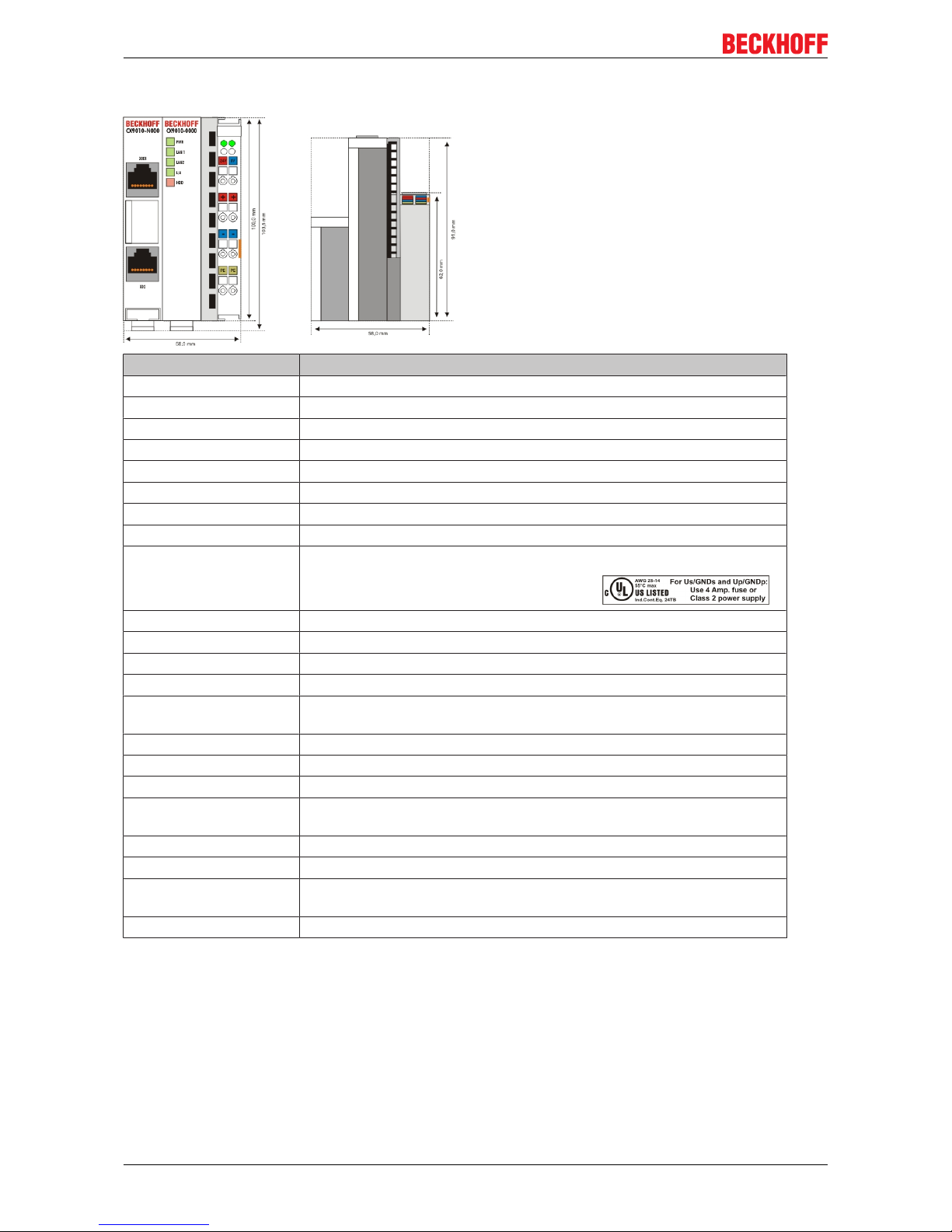
2.3.4 Technical data
Technical data CX9010-1000
Processor Intel® IXP420 with XScale® Technology, 533-MHz clock rate
Internal flash memory 32 MByte Flash (internal)
Internal main memory 128 MByte RAM (internal)
interfaces 2 x RJ 45 (internal Switch), 10/100 MBit
Diagnostics LEDs 1 x Power, 2 x LAN, 1 x K-Bus, 1 x Flash-Zugriff
Clock internal battery-backed clock for time and date
Operating system Microsoft Windows CE
Control software TwinCAT-CE-PLC-Runtime or TwinCAT-CE-NC-PTP-Runtime
Power supply 24 VDC (-15%/+20%) To meet the UL requirements use a 4 A fuse or a
power supply that has to satisfy NEC class 2!
Dielectric strength 500 V
rms
(supply/internal electronics)
I/O connection K-bus (Bus Terminals)
NOVRAM 128 kByte
I/O-DPRAM 4 kByte
Power supply I/O
terminals
2 A
Max. power loss 6.5 W (including CX9010-xxxx system interfaces)
Dimensions (W x H x D) 59 mm x 100 mm x 91 mm
weight ca. 250 g
Operating / storage
temperature
0° C ... +50° C / -25° C ... +85° C
Relative humidity 95% no condensation
Vibration/shock resistance conforms to EN 60068-2-6 / EN 60068-2-27/29
EMC resistance burst/
ESD
conforms to EN 61000-6-2/EN 61000-6-4
Protection class IP 20
Page 15
Product overview
CX9000 / CX9010 15Version: 2.6
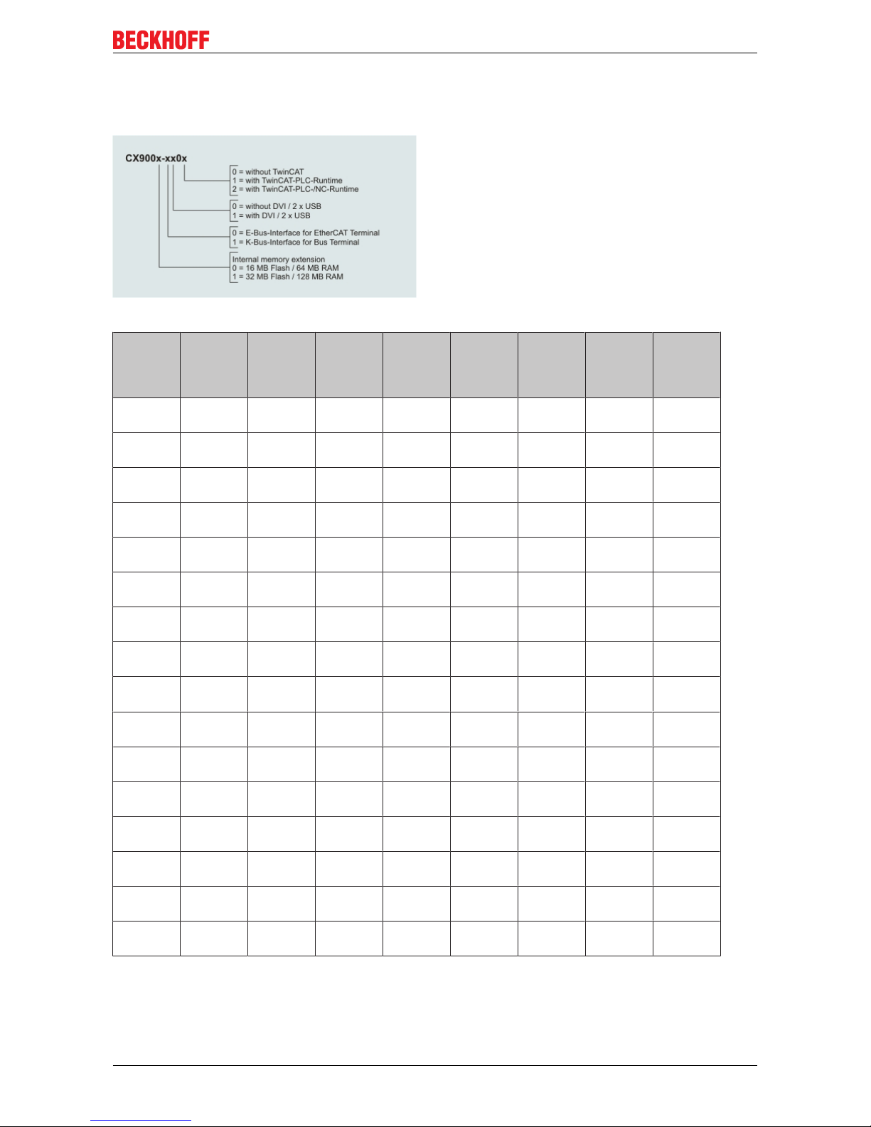
2.3.5 Configurations
The order identifier of the basic CPU module is derived as follows:
Following CX9000 configurations are available:
Ordering
information
16 MB
Flash
64 MB
RAM
32 MB
Flash
128 MB
RAM
E-Bus K-Bus DVI, 2 x
USB
no
TwinCAT
TwinCATPLC-Runtime
TwinCATNC-Runtime
CX9000
-0000
x - x - - x - -
CX9000
-0001
x - x - - - x -
CX9000
-1000
x - - x - x - -
CX9000
-1001
x - - x - - x -
CX9001
-0000
- x x - - x - -
CX9001
-0001
- x x - - - x -
CX9001
-0002
- x x - - - x x
CX9001
-0100
- x x - x x - -
CX9001
-0101
- x x - x - x -
CX9001
-0102
- x x - x - x x
CX9001
-1000
- x - x - x - -
CX9001
-1001
- x - x - - x -
CX9001
-1002
- x - x - - x x
CX9001
-1100
- x - x x x - -
CX9001
-1101
- x - x x - x -
CX9001
-1102
- x - x x - x x
Page 16
Product overview
CX9000 / CX901016 Version: 2.6
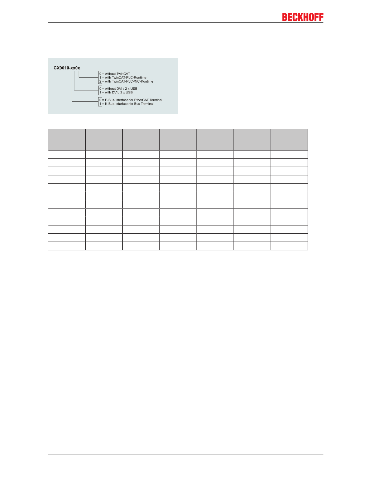
2.3.6 Configurations
The order identifier of the basic CPU module is derived as follows:
Following CX9000 configurations are available:
Ordering information
E-Bus K-Bus DVI, 2 x USB no
TwinCAT
TwinCATPLC-Runtime
TwinCATNC-Runtime
CX9010-0000 x - - x - -
CX9010-0001 x - - - x -
CX9010-0002 x - - - x x
CX9010-0100 x - x x - -
CX9010-0101 x - x - x -
CX9010-0102 x - x - x x
CX9010-1000 - x - x - -
CX9010-1001 - x - - x -
CX9010-1002 - x - - x x
CX9010-1100 - x x x - -
CX9010-1101 - x x - x -
CX9010-1102 - x x - x x
Page 17
Product overview
CX9000 / CX9010 17Version: 2.6
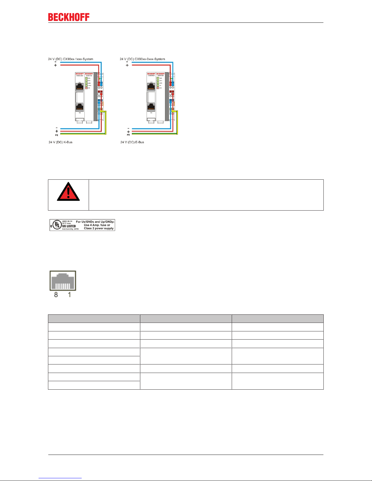
2.3.7 Connections
The system is supplied with power via the integrated power supply. This is wired as follows:
The basic module is powered via the upper connectors with 24 V DC. The terminal bus can be supplied via
the lower connections.
UL requirements
DANGER
Compliance of the UL requirements
To meet the UL requirements, the CX-Controllers must not be connected to unlimited
power sources!
CPU basic module with 2 Ethernet RJ 45 connectors:
RJ 45 interface (socket):
Table1: Assignment of the RJ45-interface, Port 1:
PIN Signal Desciption
1 TD + Transmit +
2 TD - Transmit -
3 RD + Receive +
4 connected not used
5
6 RD - Receive -
7 connected not used
8
TD & RD are exchanged at the hubs or between two PCs.
Page 18
Product overview
CX9000 / CX901018 Version: 2.6
Table2: Assignment of the RJ45 interface, Port 2:
PIN Signal Description
1 TD + Transmit +
2 TD - Transmit -
3 RD + Receive +
4 connected not used
5
6 RD - Receive -
7 connected not used
8
TD & RD are exchanged at the hubs or between two PCs.
Connection of the Ethernet ports:
Attention
Ethernet ports
The two Ethernet ports of a basic CPU module must not be connected to the same external
switch!
Note
Only for LAN
Only for use in LAN, not for connection to telecommunication circuits.
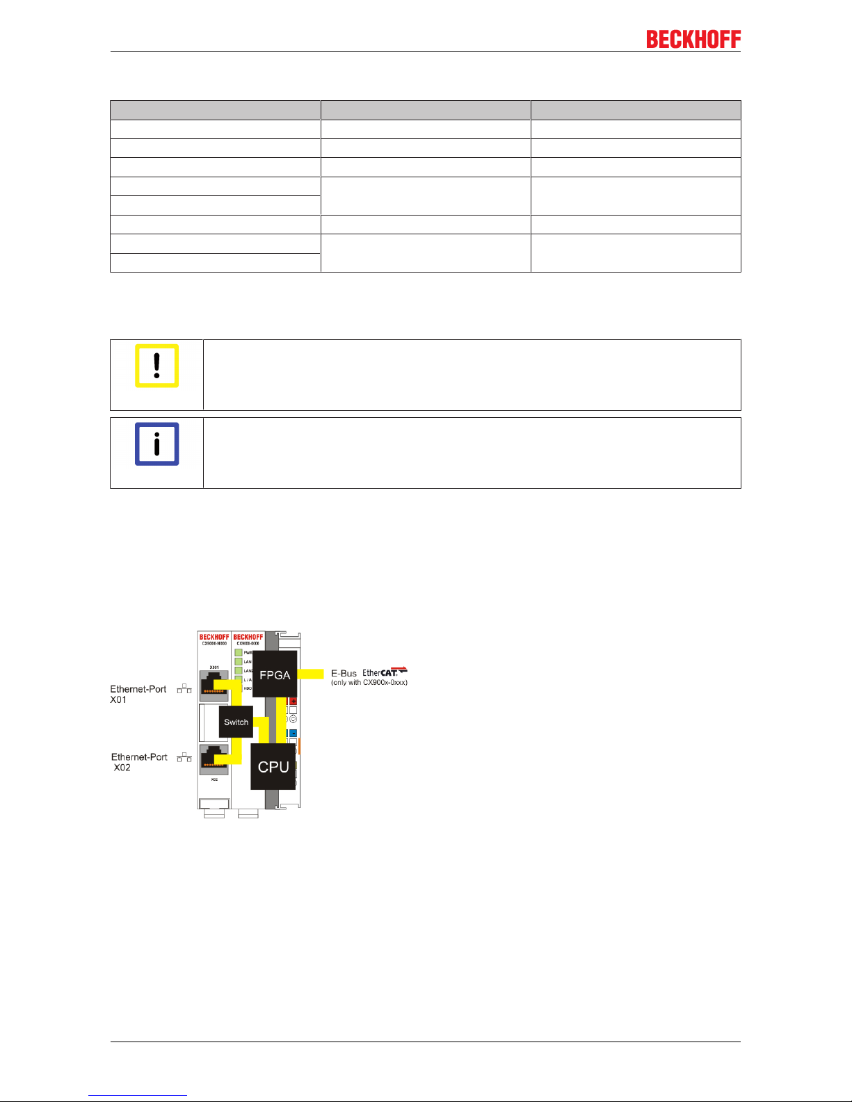
Schematic structure of the network components:
The CX90x0 features two MAC blocks. The first one (MAC1) operates the network interfaces for the Ethernet
ports. The two outputs are connected via a switch. In this way a line structure can be configured as
described below. From an operating system perspective this represents a single connection. The second
block (MAC2) operates the extended PC104 bus. The second physical network connection is used to run the
E-bus connection. (in version CX900x-0xxx) The signals are connected to and FPGA. This unit converts the
Ethernet signals to E-bus signals. So EtherCAT terminals can be connected to the system.
If K-bus is used as terminal bus (CX900x-1xxx), the second MAC-interface is not connected.
Page 19

Product overview
CX9000 / CX9010 19Version: 2.6
Operating system perspective:
The operating system only sees one of the connections for the network interface. The status is always
connected, since the switch is connected directly.
These interfaces are connected to an internal 3-port switch and offer a simple option for creating a line
topology without the need for additional Ethernet switches.
Basic CPU module with DVI/USB interface:
In addition to the two Ethernet ports, this basic module also features DVI/USB interfaces. The pin
assignment of the basic CPU module with two USB and a DVI-I interface is explained under the associated
CX90x0-N010 [}24] system interface.
Applicable to all basic CPU modules:
LED
The green power LED (PWR) is on if the basic CPU module is connected correctly to a live power supply
unit.
Compact Flash slot
Further information can be found under Compact Flash slot
Page 20
Product overview
CX9000 / CX901020 Version: 2.6
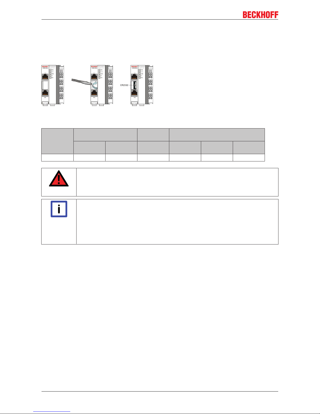
2.3.8 Battery compartment
The battery compartment is located on the left-hand side of the CPU module, between the two Ethernet
ports.
It can be opened with the aid of a screwdriver (proceed carefully in order to avoid damage).
The battery is a CR2032 type from Panasonic
with the following specification:
Battery type Electrical properties (at
20° C)
Standard
charge
Dimensions
nominal
voltage
nominal ca-
pacity
continuous
load
Diameter Height Weight
3.0 V 225 mAh 0.20 mA 20.0 mm 3.20 mm 3.1 g
DANGER
Exploding battery
Replace battery part. No. CR2032 manufactured by Sanyo or Panasonic only. Use of another battery may present a risk of fire or explosion. WARNING, battery may explode if mistreated. Do NOT recharge, disassemble or dispose of in fire.
Note
Battery maintenance
The battery must be changed every 5 years. Spare batteries can be ordered from Beckhoff
Service.Battery-recycling: Used batteries must must be disposed of in accordance with national electronics scrap regulations. Used batteries may contain harmful substances or
heavy metal that can harm the environment and health. Batteries will be recycled. They
contain important commodities as iron, zinc, nickel or manganese. The environment and
Beckhoff thank for your understanding.
Page 21
Product overview
CX9000 / CX9010 21Version: 2.6
2.3.9 CX90x0 : Dip switch settings
General
Attention
Reset the System
In general there is no need to change the dip switch settings. The switches are installed in
case of major faults, to reset the system, provide debug messages, bypass TwinCAT start
and update the image. Never change a running system !
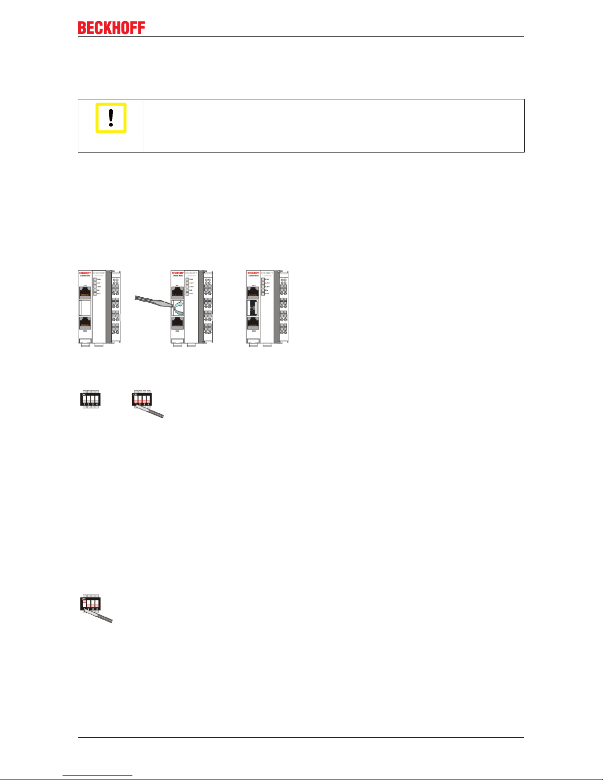
To get access to the dip switches, you have to open the over of the battery compartment. It is located
between the two ethernet connectors on the front of the CX90x0-N000 module. To open the cover proceed
as follows:
1. Power down the CX90x0
2. Open the battery compartment (located between two ethernet ports)
It can be opened with the aid of a screwdriver (proceed carefully in order to avoid damage).
Once the compartment is opened, the four dip switches can be accessed. They are located left of the battery
holder. On normal operation mode all switches are set to OFF. (All switches are down).
To change the settings of a dip switch its is advised to use a screwdriver with a small blade (2.5 mm x 7.5 cm
length and parallel shaft, Beckhoff order number: ZB8700). Use the edge to move the switches with caution!
The switches have four functions:
• Reset CX90x0-Sytem to defaults.
• Send debug codes to COM1 (if connected).
• Update mode to obtain a new image via PC server (Boot menu via COM1).
• Force TwinCAT to start in config mode.
The functions are described in detail below:
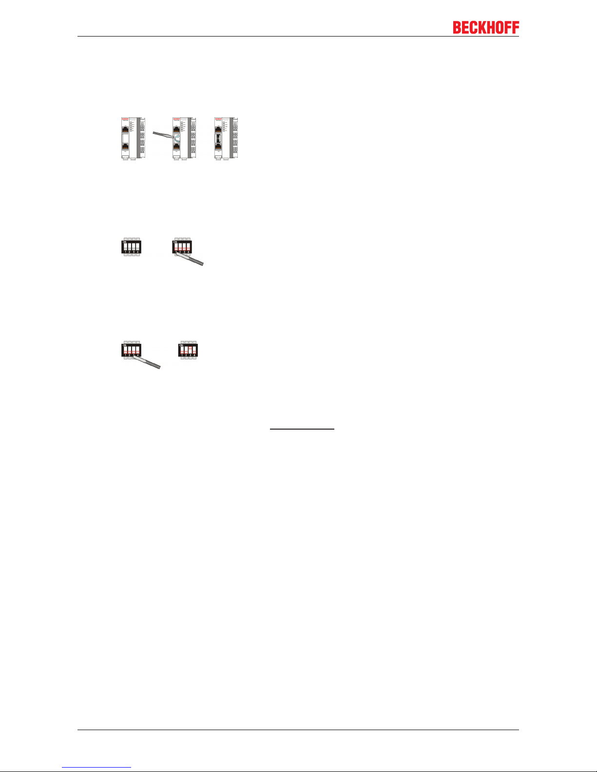
Reset to Factory Settings:
1. Set dip switch 1 to ON (move switch 1 up).
2. Connect CX-System to power and boot system. After a complete boot, the registry is regenerated.
3. Set dip switch 1 back to OFF (switch 1 down) and close cover.
Page 22

Product overview
CX9000 / CX901022 Version: 2.6
Report debug messages to COM1:
1. Set dip switch 2 to ON (move switch 2 up).
2. Connect a serial monitor device (printer or terminal) to COM1 port. The settings for the interface are:
38400 baud, 8 bits , NO parity and 1 stop bit (38400,8,N,1).
3. Connect CX-System to power and boot system. Debug messages are sent to the monitor device.
4. After finishing diagnosis power set dip switch 2 back to OFF (switch 2 down) and close cover.
Bootstrap Mode for updates:
The Bootstrap Mode is implemented for image updates. The procedure is more complex so it is described in
an own part of the documentation [}44]. Refer to the instruction for the process.
Force TwinCAT in "Config Mode":
For some cases (e.g. errors in boot project) it is necessary to start TwinCAT in Config mode. So the boot
project can be corrected or other settings can be (re)setted.
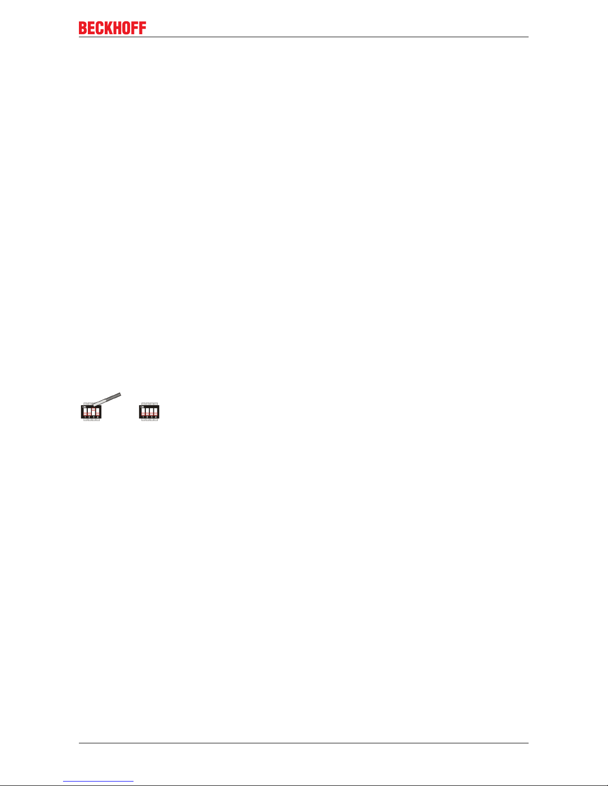
1. Set dip switch 4 to ON (move switch 4 up).
2. Connect CX-System to power and boot system.
3. Make changes to the PLC
4. power down the system. Set dip switch 4 back to OFF (switch 4 down) and close cover.
Page 23

Product overview
CX9000 / CX9010 23Version: 2.6
2.4 System interfaces
2.4.1 Technical Data
Dimensions:
Like for the other members of the CX family, a number of optional interface modules are available for the
basic CX90x0 CPU module that can be installed ex works. The following interfaces are available:
• CX90x0-N010 DVI / USB Module
• CX90x0-N030 serial interface for RS323
• CX90x0-N031 serial interface for RS422 / RS485
The CX90x0-N010 option can be connected to Beckhoff Control Panels or standard monitors with DVI or
VGA input via the DVI or USB interfaces. Devices such as printer, scanner, mouse, keyboard, mass storage,
CR-RW etc. can be connected via the USB 2.0 interfaces. The modules CX90x0-N030 offers two serial
RS232 interfaces with a maximum transfer speed of 115 kbaud. These interfaces can be implemented in
pairs as RS422/RS485, in which case they are identified as CX90x0-N031 respectively. The system
interfaces cannot be retrofitted or expanded in the field. They are supplied ex factory in the specified
configuration and cannot be separated from the CPU module. The system interfaces run through the internal
PC104 bus, so that further CX components can be connected. The power supply of the system interface
modules is ensured via the internal PC104 bus.
Technical Data CX90x0-N010 CX90x0-N030 CX90x0-N031
Interfaces 1 x DVI +
2 x USB 2.0 max. 100 mA
per port
1 x COM1+2, RS232
1 x COM3+4, RS232
1 x COM1+2, RS422/
RS485
1 x COM3+4,RS422/
RS485
Connection type DVI-I 29-pin socket + 2
USB Ports type A
2 x D-Sub plug 9-pin 2 x D-Sub plug 9-pin
Properties DVI-I interface also
carries out VGA signals
(DVI-A)
max. baud rate 115
kbaud, can not be used
simultaneously with N031/
N041
max. baud rate 115
kbaud, can not be used
simultaneously with N030/
N040
Power supply via system bus (Through internal power supply in CX90x0 module)
Dimensions 19 mm x 100 mm x 51 mm
Operating temperature 0 °C ... +55 °C
Storage temperature -25 °C ... +85 °C
Relative humidity 95% no condensations
Vibration/Shock
resistance
conforms to EN 60068-2-6 / EN 60068-2-27/29
EMC resistance burst /
ESD
conforms to EN 61000-6-2/EN 61000-6-4
Protection class IP 20
wight app. 80 g
Page 24

Product overview
CX9000 / CX901024 Version: 2.6
2.4.2 CX90x0-N010 connections
In addition to the two Ethernet interfaces, this module features a DVI-I and two USB interfaces.
Note
System interface
The system interface CX90x0-N010 can only be used in CX90x0 system with large memory
(CX9001-x00x).
DVI-I interface
The DVI-I interface transfers analog and digital data and is suitable for connection to analog graphics cards
with 15 pin D-Sub connector and digital graphics cards with DVI-D output. The resolution at the screen or the
Beckhoff Control Panel depends on the distance (maximum 5 m).
The DVI interface uses VGA signals, so that the connection of CRT VGA monitors to the CX1000 system
using a DVI to VGA adapter is also possible.
This adapter is available as an accessory.
DVI-I socket:
Pin Assignment Pin Assignment Pin Assignment
1 TMDS Data 2- 9 TMDS Data 1- 17 TMDS Data 0-
2 TMDS Data 2+ 10 TMDS Data 1+ 18 TMDS Data 0+
3 TMDS Data 2/4
Shield
11 TMDS Data 1/3
Shield
19 TMDS Data 0/5
Shield
4 not connected 12 not connected 20 not connected
5 not connected 13 not connected 21 not connected
6 DDC Clock 14 + 5V Power 22 TMDS Clock
Shield
7 DDC Data 15 Ground ( +5V,
Analog H/V
Sync)
23 TMDS Clock +
8 Analog Vertical
Sync
16 Hot Plug Detect 24 TMDA Clock -
Pin assignment (cross)
Page 25

Product overview
CX9000 / CX9010 25Version: 2.6
Pin Assignment
C1 Analog Red Video Out
C2 Analog Green Video Out
C3 Analog Blue Video Out
C4 Analog Horizontal Sync
Resolution at the monitor:
Resolution in pixels Distance of the interface from the monitor
1600 x 1200 5 m
1280 x 1024 5 m
1024 x 768 5 m
800 x 600 5 m
640 x 480 5 m
USB interface:
The USB socket is a type A socket. The USB interface complies to USB 2.0 specification
Pin Assignment Typical assignment
1 VBUS Red
2 D- White
3 D+ Green
4 GND Black
Shell Shield Drain Wire
Page 26

Product overview
CX9000 / CX901026 Version: 2.6
2.4.3 CX90x0-N030 connections
The CX90x0-N030 system interface features two RS232 interfaces, COM1 and COM2 (9 pin Sub-D plug
connector).
The maximum baud rate on all channels is 115 kBit. The pin assignment for all interfaces is equal and
described below. The interface parameter can be set in the operating system or in the PLC program.
RS232 COM interface (connector):
Table3: Pin assignment COM interface:
PIN Signal Type Description
1 DCD Signal in Data Carrier Detected
2 RxD Signal in Receive Data
3 TxD Signal out Transmit Data
4 DTR Signal out Data Terminal Ready
5 GND Ground Ground
6 DSR Signal in Dataset Ready
7 RTS Signal out Request to Send
8 CTS Signal in Clear to Send
9 RI Signal in Ring Indicator
Note
System interface
The system interface CX90x0-N030 can only be used instead and not simultaneously with
system interface CX90x0-N031.
Page 27
Product overview
CX9000 / CX9010 27Version: 2.6
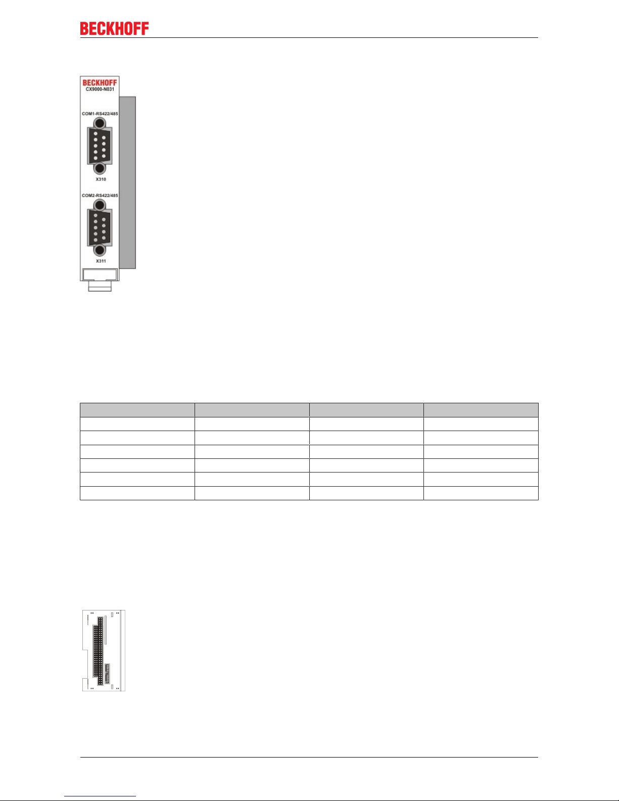
2.4.4 CX90x0-N031 connections
The CX90x0-N031 system interface features two RS422 / RS 485 interfaces, COM1 and COM2 (9 pin Sub-D
plug connector).
The maximum baud rate on all channels is 115 kBit. The pin assignment for all interfaces is equal and
described below. The interface parameter can be set in the operating system or in the PLC program.
RS232 COM interface (connector):
Table4: Pin assignment COM interface:
PIN Signal Type Description
2 TxD+ Data-Out + Transmit 422
3 RxD+ Data-In + Receive 422
5 GND Ground Ground
6 VCC VCC +5V
7 TxD- Data-Out - Transmit 422
8 RxD- Data-In - Receive 422
For RS 485 Pin 2 and 3 ( Data +) as well as Pin7 and 8 (Data -) have to be connected..
Setting the interface parameter
If the system interface CX90x0-N031 resides at the end of the CX90x0-system block, it is easy to access the
dip switches. The dip switches for the configuration of the RS485/422 interfaces can be found at the left side
of the module. If you remove the grey cover you can see the switch:
The upper switch sets the parameters for the upper interface, the lower switch sets the parameter for the
lower interface. The system must be powered down, if the settings of the switches are changed! The settings
for default use should be mentioned by ordering the interface module.
Page 28

Product overview
CX9000 / CX901028 Version: 2.6
Settings DIP switches RS485:
Table5: RS485 without Echo, End-Point ( Terminated) DEFAULT setting
DIP Status Function
1 off Echo on
2 on Echo off
3 on Auto send on
4 off Always send on
5 on Auto receive on
6 off Always receive on
7 on Term on
8 on Term on
Table6: RS485 with Echo, End-Point ( Terminated)
DIP Status Function
1 on Echo on
2 off Echo off
3 on Auto send on
4 off Always send on
5 off Auto receive on
6 on Always receive on
7 on Term on
8 on Term on
Table7: RS485 without Echo, Drop-Point ( without Termination)
DIP Status Function
1 off Echo on
2 on Echo off
3 on Auto send on
4 off Always send on
5 off Auto receive on
6 on Always receive on
7 off Term on
8 off Term on
Table8: RS485 with Echo, Drop-Point ( without Termination)
DIP Status Function
1 on Echo on
2 off Echo off
3 on Auto send on
4 off Always send on
5 off Auto receive on
6 on Always receive on
7 off Term on
8 off Term on
Page 29

Product overview
CX9000 / CX9010 29Version: 2.6
Setting DIP-Switches RS422:
Table9: RS422 full duplex end point
DIP Status Function
1 on Echo on
2 off Echo off
3 off Auto send on
4 on Always send on
5 off Auto receive on
6 on Always receive on
7 on Term on
8 on Term on
Note
System interface
The system interface CX90x0-N031 can only be used instead and not at the same time
with system interface CX90x0-N030.
Also see about this
2 Removal and disposal [}42]
Page 30

Transport
CX9000 / CX901030 Version: 2.6
3 Transport
3.1 Unpacking, installation and transport
The specified storage conditions must be adhered to (see "Technical data").
Dimensions and weight of the individual modules:
Dimensions (W x H x D): 19 x 100 x 91 mm (system interface) , 58 x 100 x 91 mm (basic module)
Weight: 80 g (system interface) to 250 g (basic module)
Unpacking
Proceed as follows to unpack the unit:
1. Remove packaging.
2. Do not discard the original packaging. Keep it for future relocation.
3. Check the delivery for completeness by comparing it with your order.
4. Please keep the associated paperwork. It contains important information for handling the unit.
5. Check the contents for visible shipping damage.
6. If you notice any shipping damage or inconsistencies between the contents and your order, you should
notify Beckhoff Service.
Attention
Danger of damage to the unit
During transport in cold conditions, or if the unit is subjected to extreme temperature
swings, condensation on and inside the unit must be avoided.
Prior to operation, the unit must be allowed to slowly adjust to room temperature. Should
condensation occur, a delay time of approximately 12 hours must be allowed before the
unit is switched on.
Installation
The devices are designed for installation in control cabinets. You will find installation instructions in the
chapter mechanical mounting.
Shipping and relocation
Despite the robust design of the unit, the components are sensitive to strong vibrations and impacts. During
transport, your computer should therefore be protected from excessive mechanical stress. Therefore, please
use the original packaging.
Page 31

Assembly and connecting
CX9000 / CX9010 31Version: 2.6
4 Assembly and connecting
4.1 Mechanical assembly
4.1.1 Dimensions
The CX90x0 product range is characterized by small overall installed size and high modularity. For project
planning purposes, a CPU module, a power supply unit and the associated system interfaces and fieldbus
interfaces have to be provided. The overall width of the application is made up of the individual modules.
With a height of 100 mm, the module dimensions exactly match those of the Beckhoff Bus Terminals.
Together with the lowered connector surfaces, this means that it can be used in a standard terminal box with
a depth of 120 mm.
Attention
Cooling the device
To ensure cooling to the device in operation it is important keep the safety distances.
CX90x0-x000 CPU Basic module:
without heat sink:
with heat sink:
Page 32

Assembly and connecting
CX9000 / CX901032 Version: 2.6
CX90x0-N0x0 System interfaces:
Page 33

Assembly and connecting
CX9000 / CX9010 33Version: 2.6
4.1.2 Mechanical assembly of the basic module
The installation of the modules takes place in three steps:
1. The sequence of the modules
The basic CPU module with system interfaces, which are factory-installed on the left side, is extended with
the power supply unit on the right and with the fieldbus connection (master or slave) left side if available.
2. Engaging on the top-hat rail
On the bottom of the modules, there is a white tension strap, which is connected with a latching mechanism.
These tension straps must be pulled down before attaching to the top-hat rail. This can be done using an
ordinary screwdriver and a slight turn.
Then fix the CX9000 block on the top hat-rail using the latching straps. You should hear a soft click.
Only apply pressure at insensitive points of the housing (edges). Never apply pressure on the display, the
buttons or movable parts of the CX-system.
After successful latching on the top-hat rail the straps should be pushed back to their original position.
Note:
A locking mechanism prevents the individual housings from being pulled off again. Detailed information
relating to disassembly of the CX-System configuration from the top-hat rail can be found on page "Removal
and disposal [}42]".
Installation position:
Attention
Mounting the device
The maximum ambient temperature for CPU modules mounted on a top-hat rail is 55°C.
The orientation in which the device is fitted must be selected in such a way that cooling air
can flow vertically through the ventilation holes. The images show the correct installation
position. Observe minimum clearance!Mounting must provide a clearance of 30 mm both
above and below a CX90xx device combination to ensure adequate ventilation of the base
CPU module and the power supply unit.
Page 34

Assembly and connecting
CX9000 / CX901034 Version: 2.6
Correct installation position:
The high-performance CX9000 system generates a significant amount of heat, which is dissipated via a
passive ventilation system. This system requires the unit to be mounted correctly. Ventilation openings are
located at the top and bottom of the housing. The system can be installed in the following positions:
The following positions are invalid:
4.1.3 Mechanical installation of the UPS Module
Note
The power fail signal
The UPS module for CX90x0 is not fully supported by TwinCAT yet.The UPS module
should be connected the described way. To get the power fail signal (pin 3 on UPS) must
be connected to a digital input terminal. In this way the PLC can access the power fail signal and save the data or shut down the system. The shutdown time can only be set by the
selector on the front side of the UPS (best choice is 0).In case of shutdown the UPS will
restart the system after power fail.
0. Switching off and disconnecting the power supply
Before a CX90x0 system can be dismantled, the system should be switched off, and the power supply
should be disconnected.
1. Removing from the top-hat rail:
Before the individual CX90x0 modules are disconnected, the whole CX90x0 hardware block should be
removed from the top-hat rail. Proceed as follows:
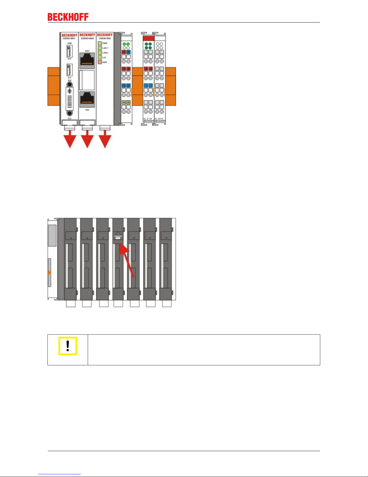
1.1. Release and remove the first Terminal next to the power supply unit on the top-hat rail.
First remove any wiring from power supply unit and then from the first terminal on the top-hat rail next to the
power supply unit. If the wiring is to be reused for another system, it is advisable to make a note of the
connections. Then pull the orange terminal release (see arrow) to release the terminal and pull it out.
Page 35

Assembly and connecting
CX9000 / CX9010 35Version: 2.6
1.2. Releasing the CX90x0 system
In order to release the CX-block, pull the white straps at the bottom of the module in the direction of the
arrows. They will lock in the extended position. After pulling the terminal release of the power supply unit, the
block can be removed carefully from the top-hat rail.
2 Assembly of the CPU basic module with UPS module
2.1 Assembly the the CX90x0 system block
In order to be able to connect the UPS to the basic CX90x0 module, the cover of the basic module has to be
removed first. This is achieved by applying slight pressure on the cover. The individual modules are simply
plugged together. The PC104 connector plugs should be handled carefully in order to avoid damage. When
correctly assembled, no significant gap can be seen between the attached housings. If the modules are
assembled the cover can be replaced.
2.2 Engaging on the top-hat rail
Before engaging the system back on the top-hat rail the user should ensure all white tension straps are
pulled down. The user should take care of the space between the terminals and the Embedded PC system.
The space for the removed terminal must be kept to reinstall the terminal.
Page 36

Assembly and connecting
CX9000 / CX901036 Version: 2.6
Then fix the CX90x0 block on the top hat-rail using the latching straps. You should hear a soft click.
Only apply pressure at insensitive points of the housing (edges). Never apply pressure on the display, the
buttons or movable parts of the CX10x0 system.
After successful latching on the top-hat rail the straps should be pushed back to their original position.
2.3 Connecting the Embedded PC to the terminal bus
By reinstalling the once removed terminal the system is connected to the bus.
Finally the wiring must be reinstalled. The removed terminal is reconnected as before. The power supply is
now connected via the UPS-connectors. (see chapter connections for details)
Page 37

Assembly and connecting
CX9000 / CX9010 37Version: 2.6
4.2 Start-up procedure
4.2.1 Switching the PC on and off
Switching on
The power supply for the basic CPU module comes from the power supply unit. The basic CPU module
starts automatically when the power supply unit is connected to the mains.
Switching on for the first time
When you switch on the PC for the first time, the pre-installed operating system (optional) will be started.
Switching off
The Embedded PC switches off when the power supply unit is switched off. The control software typically
running on Embedded PCs should be shut down or stopped correctly. A user who may not close software
may also not switch the Embedded PC off, since data can be lost from the hard disk by switching off while
software is running.
Once the software has been stopped, the operating system can be shut down. Only then should the power
supply be interrupted.
Page 38

Error handling and diagnostics
CX9000 / CX901038 Version: 2.6
5 Error handling and diagnostics
5.1 CPU basic module
5.1.1 LEDs Basic CPU-module (E-Bus)
The behavior of the CX9000 and the CX9010 is identical. As reference the LED behavior of the CX9000 is
shown below.
Display LED Meaning
PWR red TwinCAT is in STOP mode
green TwinCAT is in RUN mode
blue TwinCAT is in CONFIG mode
off System is offline
LAN 1 LAN Link , (green) LINK/ACTIVITY for first switched LAN
PORT (CX9000_N000)
LAN 2 LAN Link, (green) LINK/ACTIVITY for second switched
LAN PORT (CX9000_N000)
L / A (Link Activity) flashes in traffic on E-bus.
HDD Read/Write Compact Flash (red) Indicates access to the
CF card.
5.1.2 LEDs Basic CPU-module (K-Bus)
The behavior of the CX9000 and the CX9010 is identical. As reference the LED behavior of the CX9000 is
shown below.
Display LED Meaning
PWR red TwinCAT is in STOP mode
green TwinCAT is in RUN mode
blue TwinCAT is in CONFIG mode
off System is offline
LAN 1 LAN Link , (green) LINK/ACTIVITY for first switched LAN
PORT (CX9000_N000)
LAN 2 LAN Link, (green) LINK/ACTIVITY for second switched
LAN PORT (CX9000_N000)
L / A (Link Activity) flashes in traffic on E-bus.
K-Bus Flashes in traffic on K-bus / reports errors K-Bus not
active (off)
K-Bus running (flashes green)
K-Bus error (red) see tables below
HDD Read/Write Compact Flash (red) Indicates access to the
CF card
Table10: The I/O error K-Bus LED blink code
Fast blinking Start of the error code
First slow sequence Error code
Second slow sequence Error code argument
Page 39

Error handling and diagnostics
CX9000 / CX9010 39Version: 2.6
LEDs for K-Bus diagnosis
Error code Error code argument Description Remedy
Persistent,
continuous
blinking
EMC problems - Check power supply for
overvoltage or undervoltage peaks
- Implement EMC measures
- If a K-Bus error is present, it can
be localised by a restart of the
power supply (by switching it off
and then on again)
1 pulse 0 EEPROM checksum
error
Revert to the manufacturer’s
setting
1 Code buffer overflow Insert fewer Bus Terminals. The
programmed configuration has too
many entries in the table
2 Unknown data type Software update required for the
power supply
2 pulses 0 Programmed
configuration has an
incorrect table entry
Check programmed configuration
for correctness
n (n > 0) Table comparison (Bus
Terminal n)
Incorrect table entry
3 pulses 0 K-Bus command error - No Bus Terminal inserted
- One of the Bus Terminals is
defective; halve the number of Bus
Terminals attached and check
whether the error is still present
with the remaining Bus Terminals.
Repeat until the defective Bus
Terminal is located.
4 pulses 0 K-Bus data error, break
behind the power supply
Check whether the n+1 Bus
Terminal is correctly connected;
replace if necessary.
n Break behind Bus
Terminal n
Check whether the Bus End
Terminal 9010 is connected.
5 pulses n K-Bus error in register
communication with Bus
Terminal n
Exchange the nth bus terminal
9 pulses 0 Checksum error in Flash
program
Revert to the manufacturer’s
setting
n (n>0) Bus Terminal n is not
consistent with the
configuration that existed
when the boot project
was created
Revert to the manufacturer's
setting which will clear the boot
project.
14 pulses n nth Bus Terminal has the
wrong format
Start the power supply again, and
if the error occurs again then
exchange the Bus Terminal.
15 pulses n Number of Bus
Terminals is no longer
correct
Start the power supply up again.
16 pulses n Length of the K-Bus data
is no longer correct
Start the power supply up again.
Error code argument
The number of pulses indicates the position of the last Bus Terminal before the fault. Passive Bus Terminals,
such as a power feed terminal, are not included in the count.
Page 40

Error handling and diagnostics
CX9000 / CX901040 Version: 2.6
In the case of some errors, rectification does not cause the power supply to leave the blink sequence. The
power supply can only be restarted by switching its supply voltage off and on again.
5.1.3 Terminal Bus Analysis in PLC-Program
To analyze the terminal bus (K-Bus) the programmer can access the registers described in the architecture.
The access to the PLC-program is realized via TwinCAT. The registers are described in the architecture of
the terminal bus connectors (CX1100-000x).
For analysis four signals / variables are used:
• BusState (describes the state of the bus: 0 -> no error, 1 -> bus error)
• ErrorCode (same error code as the LED blink code)
• ErrorArg (same argument code LED blink code)
• Request[0] (output to request error codes / reset bus)
In the PLC program some external variables must be defined :
VAR
k_bus_request AT %QX0.0 : BOOL;
k_bus_err_code AT %IB0 : USINT;
k_bus_err_arg AT %IB1 : USINT;
k_bus_state AT %IB2 : USINT;
END_VAR
In the PLC program the analysis can be done as follows: (this is only pseudo code)
....
IF k_bus_state = 1 THEN (* an error occured on K-Bus*)
k_bus_request := TRUE; (* request vaules for ErrCode and ErrArg *)
CASE k_bus_err_code OF
0 : return;(* should not happen, though an error occured *)
1 : CASE k_bus_arg OF
0 : report error; (* EEPROM checksum error *)
1 : report error; (* overflow in code buffer *)
2 : report error; (* unknown datatype *)
END_CASE;
2 : CASE k_bus_arg OF
0 : report error; (* programmed configuration, wrong table entry *)
ELSE report error; (* wrong table entry *)
END_CASE;
3 : report error (* K-Bus command error *)
4 : CASE k_bus_arg OF
0 : report error; (* break after power supply *)
ELSE report error; (* break after terminal 'k_bus_arg' *)
END_CASE;
5 : report error (* K-Bus-error during register-communication with terminal 'k_bus_arg' *)
9 : CASE k_bus_arg OF
0 : report error; (* checksum error in program flash *)
ELSE report error; (* terminal 'k_bus_arg' does not exist in boot configuration *)
END_CASE;
14 : report error (* 'k_bus_arg'-th terminal has wrong format *)
15 : report error (* wrong number of bus terminals *)
16 : report error (* length of K-Bus data is invalid *)
END_CASE
k_bus_request := TRUE; (* reset bus, if reason for error is removed, bus starts again *)
....
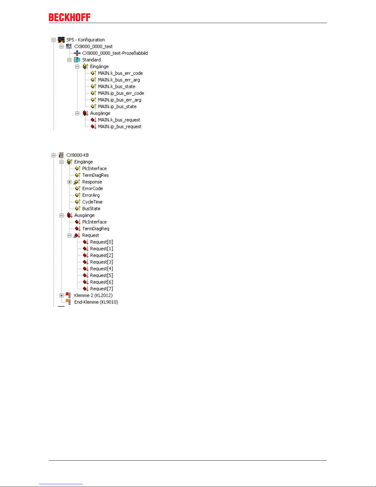
To make the control work, the register and the program must be linked in System Manager. If the PLC
program is attached in System Manager the following signals are available:
Page 41
Error handling and diagnostics
CX9000 / CX9010 41Version: 2.6
Analog the registers of the terminal bus are shown in System Manager :
Link signals and variables :
k_bus_err_code with ErrorCode
k_bus_err_arg with ErrorArg
k_bus_state with BusState
and
k_bus_request with Request[0]
If all signals are linked the programmer can load configuration and PLC program onto the system.
Page 42

Decomissioning
CX9000 / CX901042 Version: 2.6
6 Decomissioning
6.1 Removal and disposal
A CX90x0 hardware configuration is dismantled in 2 stages:
0. Switching off and disconnecting the power supply
Before a CX-System can be dismantled, the system should be switched off, and the power supply should be
disconnected.
1. Removing from the top-hat rail:
Before the individual CX-System modules are disconnected, the whole CX-hardware block should be
removed from the top-hat rail. Proceed as follows:
1.1. Release and remove the first Terminal next to the power supply unit on the top-hat rail.
First remove any wiring from power supply unit and then from the first terminal on the top-hat rail next to the
power supply unit. If the wiring is to be reused for another system, it is advisable to make a note of the
connections. Then pull the orange terminal release (see arrow) to release the terminal and pull it out.
1.2. Releasing the CX-System
In order to release the CX-block, pull the white straps at the bottom of the module in the direction of the
arrows. They will lock in the extended position. After pulling the terminal release of the power supply unit, the
block can be removed carefully from the top-hat rail.
Page 43
Decomissioning
CX9000 / CX9010 43Version: 2.6
2. Separating the individual modules
2.1. Separating the power supply unit, the CX-System CPU and other components
Place the CX-block onto a suitable support with the front facing down. Then insert a flat screwdriver with
dimensions 1.0 x 5.5 x 150 mm into the locking mechanism, and then operating the slider by turning it about
90 degrees. The locking mechanism on the rear affects an approx. 2-3 mm wide clearance of the module
latching mechanism, pushing them apart. The plug connectors of the PC 104 interface can then be pulled
apart carefully.
Only modules (CPU, fieldbus connections and UPS modules) that can be separated non-destructively
feature a release device. Modules that cannot be separated only feature a marking point (with or without red
paint seal). Applying force to these elements will destroy them.
Attention
Forcibly opening the module housing
Forcibly opening the module housing (e.g. removing the cover) will destroy the housing.
Disposal
The device must be fully dismantled in order to dispose of it.
Electronic parts must be disposed of in accordance with national electronics scrap regulations.
Page 44

Appendix
CX9000 / CX901044 Version: 2.6
7 Appendix
7.1 CX90x0 : Update Image
General
Note
Image update
In general an update of the image is not necessary : The basic functionality of TwinCAT
and TwinCAT PLC are working fine. Update the Image ONLY if there is an advice from
BECKHOFF Automation GmbH. Never change a running system !
If the image update is required, here some basic information for overview:
The diagram shows the flow of the update process. There are three main steps:
Page 45

Appendix
CX9000 / CX9010 45Version: 2.6
1. Select the correct image
2. Installation of image
3. Copy files to "Hard Disk"
Each step can be completed in different ways.
Select the correct image
Images on the BECKHOFF FTP-server
The new images reside on the FTP-Server of the Beckhoff Automation GmbH:
ftp.beckhoff.de/Software/embPC-Control/
The following diagrams show the view of the FTP-Server.
FTP-Directory /Software/embPC-Control/ auf ftp.beckhoff.de.
Beckhoff FTP Server ftp.beckhoff.com
No unauthorised access to our systems is allowed!
Please report operational problems to webadmin@beckhoff.com
<DIR> ..
07/30/09 11:09PM [GMT] <DIR> C65xx
04/23/10 10:00AM [GMT] <DIR> C6915
07/30/09 11:17PM [GMT] <DIR> C69xx
04/20/11 01:11PM [GMT] <DIR> CB3052-CB3054
02/26/10 12:38PM [GMT] <DIR> CE
06/28/11 01:13PM [GMT] <DIR> CP62xx
10/17/11 09:53AM [GMT] <DIR> CP6608
10/17/11 09:54AM [GMT] <DIR> CP66xx
07/31/09 01:52AM [GMT] <DIR> CP72xx
06/30/11 11:29AM [GMT] <DIR> CPx7xx
06/30/11 01:03PM [GMT] <DIR> CX10xx
07/20/10 12:10PM [GMT] <DIR> CX50xx
07/31/09 10:50AM [GMT] <DIR> CX9000
07/31/09 10:51AM [GMT] <DIR> CX90xx
08/08/11 11:50AM [GMT] <DIR> Solution
09/23/11 10:21AM [GMT] <DIR> WES7
07/05/11 12:55PM [GMT] <DIR> XPe
CX90xx CX9000 ..
For CX9000 select Link CX9000.
Page 46

Appendix
CX9000 / CX901046 Version: 2.6
FTP-Directory /Software/embPC-Control/CX9000/CE/ auf ftp.beckhoff.de.
Beckhoff FTP Server ftp.beckhoff.com
No unauthorised access to our systems is allowed!
Please report operational problems to webadmin@beckhoff.com
<DIR> ..
10/17/11 09:55AM [GMT] 6,735,682 CX9000_CE500_LF_v226.zip
10/17/11 09:55AM [GMT] 8,971,992 CX9000_CE600_LF_v312.zip
02/23/11 06:46PM [GMT] 98,959 CX9000_ImageUpdate.zip
CX9000_ImageUpdate.zip CX9000_CE600_LF_v312.zip CX9000_CE500_LF_v226.zip ..
CX9000_CE500_LF_v226.zip
Image for CE5.0
CX9000_CE600_LF_v312.zip
Image for CE6.0
CX9000_ImageUpdate.zip
Image-server and Enable Update-Tool for Update via the Update-Server and Update-Tool for direct update.
For CX9001 and CX9010 select link CX90xx.
FTP-Directory /Software/embPC-Control/CX90xx/CE/ on ftp.beckhoff.de.
Beckhoff FTP Server ftp.beckhoff.com
No unauthorised access to our systems is allowed!
Please report operational problems to webadmin@beckhoff.com
<DIR> ..
02/23/11 06:46PM [GMT] 98,959 CX9000_ImageUpdate.zip
09/22/08 12:32PM [GMT] 5,278,516 CX90x0_NoHive_32MB_Flash.zip
10/17/11 09:55AM [GMT] 15,903,461 CX90xx_CE500_HMI_v226.zip
10/17/11 09:56AM [GMT] 19,347,515 CX90xx_CE600_HPS_v312.zip
CX90xx_CE600_HPS_v312.zip CX90xx_CE500_HMI_v226.zip CX90x0_NoHive_32MB_Flash.zip
CX9000_ImageUpdate.zip ..
CX90xx_CE500_HMI_v226.zip
Image for CE5.0
CX90xx_CE600_HPS_v312.zip
Image for CE6.0
CX90x0_NoHive_32MB-Flash.zip
empty image to delete /Hard Disk
CX9000_ImageUpdate.zip
Image-server and Enable Update-Tool for Update via the Update-Server.
Page 47

Appendix
CX9000 / CX9010 47Version: 2.6
Flashing operating system
Interactive tool on CX90x0:
First the program "Cx9ImageUpdate.exe" must be downloaded from BECKHOFF FTP-Server. If the CX90x0
has no USB the tool can be transferred via ftp onto the system. Use CERHOST-Tools to control the CX90x0
remote via Ethernet. Activate the FTP server on the CX, if not it is disabled. The necessary configuration is
shown below:
Page 48
Appendix
CX9000 / CX901048 Version: 2.6
It is a good idea to choose "\Temp" or "\Public" as target directory, though this range is mapped into the RAM
regions instead of the hard disc located in flash memory. For operation the system must be rebooted. Just
follow the instructions on the screen. After restart of the CX90x0 the program can be copied easily to the
CX90x0 with the explorer:
If there is enough free space on the CX90x0 (big memory) the image can be copied together with to tool.
Otherwise the image file can be accessed via network drive. In this case you should map the drive to the
CX90x0:
Page 49

Appendix
CX9000 / CX9010 49Version: 2.6
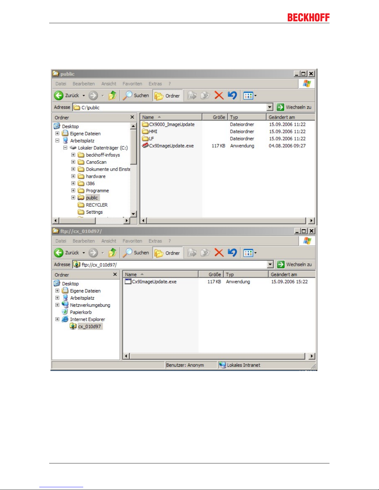
If the image is copied to the CX90x0 or the network drive is mapped to the system the update tool can be
started by double click on the icon. The program ask for the filename of the image. The complete path to the
file must be entered now. Depending on the network configuration the password is requested again.
Page 50

Appendix
CX9000 / CX901050 Version: 2.6
After click on "FLASH IMAGE" button a request box appears to confirm the image file. This is the last chance
to abort the update process.
When confirming the image file a warning appears on the screen.
The progress is shown in the status line in the bottom of the tool.
Page 51

Appendix
CX9000 / CX9010 51Version: 2.6
When the update is complete the following message appears in the status field:
The CX90x0 can be rebooted now. If the system has started again The last step can be done.
Imageserver on Host PC
1. Prepare Image-Server (once)
Provide the image server on the host PC, the components are :
• Two batchfiles "CxImgSrv_HMI.bat" and "CxImgSrv_LF.bat"
Note that the CX90x0 is shipped with different hardware environment (e.g. more or less flash memory).
• Folder "\Tools" contains the image server itself : CxImageSrv.exe
• Folder "\Images" contains the HMI and LF subfolders with the required file "Boot.bin"
If you receive a new NK.BIN file, just rename it to "Boot.bin" and provide it in the correct subfolder
2. Prepare CX90x0
Prepare the "Boot-Strap Mode" on CX90x0. There are two ways to set the CX90x0 into "Boot-Strap Mode":
First the DIP-switch version is described.
Page 52
Appendix
CX9000 / CX901052 Version: 2.6
1. Power down the CX90x0.
2. Open the battery compartment (located between two ethernet ports)
It can be opened with the aid of a screwdriver (proceed carefully in order to avoid damage).
3. If the clack is opened, you can access to the four Dip switches. They are placed on the left side of the
battery mount. In the normal operation state all swiches are set to OFF ( all switches are placed
down).
To change the settings, use a screw driver with a short top (2.5 mm x 7.5 mm length and parallel
top, Beckhoff order number ZB8700). Be careful with the top, don´t damage the device. Find the
dip switches 1,2,3,4 and set switch 3 from OFF to ON (switch 3 placed top). If the Dip Switches
are protected with a foil, it´s necessary to breakthrough that foil.
Start a program, that sets the CX90x0 in the "Boot-Strap Mode".
Alternative the administrator can start a tool on the CX-Systems to set the CX90x0 into "Boot-Strap Mode".
First the program must be downloaded from the BECKHOFF FTP-Server. If the CX90x0 has no USB the tool
can be transferred via ftp onto the system. Use CERHOST-Tools to control the CX90x0 remote via Ethernet.
Activate the FTP server on the CX, if not it is disabled. The necessary configuration is shown below:
Page 53

Appendix
CX9000 / CX9010 53Version: 2.6
It is a good idea to choose "\Temp" or "\Public" as target directory, though this range is mapped into the RAM
regions instead of the hard disc located in flash memory. For operation the system must be rebooted. Just
follow the instructions on the screen. After restart of the CX90x0 the program can be copied easily to the
CX90x0 with the explorer:
Page 54

Appendix
CX9000 / CX901054 Version: 2.6
Attention
Starting CERHOST
Via CERHOST the program will be started with a double click on the icon. Warning: Do
NOT start the program if you have no image-Server ( see below) AND a correct image! The
CX90x0 is now no longer useable for PLC until an update was made!The reset to operational is done automatically if the the update has taken place.
Note
Image Server
Image server will listen in complete network to be contacted by CX90x0 Two solutions to be
sure that you just update your CX90x0 device.... and not others in network ! (for details see
network notes below)
4. Start image server
Start the image server on the host PC :
Page 55
Appendix
CX9000 / CX9010 55Version: 2.6
• start the correct batch file "CxImgSrv_HMI.bat" or "CxImgSrv_LF.bat" (to let image-server provide the
HMI or the LF image in network)
The batch file will start a command-shell and prompt : "Waiting for download request..."
5. Phases during image update
Start CX90x0 to initiate the download procedure :
• Initial phase :
Start CX90x0 to initiate the download procedure :power on CX90x0
The CX90x0 tries to find an image server on network to download an image.
• Download phase :
Image server will prompt a message in command shell if an image is downloaded to CX90x0
Message is like :
Boot image request from device CX90x0_BA23
Working directory is Image\HMI
Calling TFTP.exe -i <CX90x0-IP> PUT boot.bin
On CX90x0 the HDD led will light up : The CX- device is erasing and copying new image.
• Reorganisation phase :
The image server will prompt a message, that the download of new image has been finished.
Now, close command shell. (Press <CTRL> + <c> or close the window)
• Set system back to operation mode; to avoid the system to run the update procedure again. Set
the dip switch 3 back to "off" and close the battery compartment.
NOTES on network configuration :
• Image server will listen in complete network to be contacted by CX90x0
Two solutions to be sure that you just update your CX90x0 device.... and not others in network !
1a.
provide a subnet (like a second network card in host PC)
or
1b.
connect host-pc and CX90x0 directly without involving company network
or
2.
The image server can be configured to let CX directly request image from specific IP address.
Step 1 : connect CX90x0 with PC, get IP address of PC like 192.16.18.123
Step 2 : edit the image-server-batch-file and add the IP address to the command line. (Sample :
Tools\CxImageSrv Images\HMI 192.16.18.123 )
Step 3 : proceed with booting CX90x0 in boot strap mode. Now the CX will try do request image
from IP address 192.16.18.123
Page 56

Appendix
CX9000 / CX901056 Version: 2.6
Copy files to Harddisk
To make the new image work perfectly new configuration and program files are needed. They must be
copied to the internal flash. There are two ways to make the files accessible to the system. If the system
consists of interfaces CX9000-N010 or CX9000-N070 a USB-stick can hold the files. The system interface
CX9000-A001 can make the files available via a CF-card. If there are none of the suggested system
interfaces the files must be made available via a network drive (see above)
Next step is to delete the files on the internal flash. To do so just delete all files on "/Hard Disk". All files that
can not be deleted must be renamed.
Now all files from the archive can be copied to the "Hard Disk". When all files are copied reboot the system.
The renamed files can be deleted and the update is complete.
Page 57

Appendix
CX9000 / CX9010 57Version: 2.6
7.2 Accessories
Compact flash cards
Order number for the initial order of a compact flash card (instead of the 128 MB compact flash card)
Order number Description
CX1900-0023 1 GB compact flash card, extended temperature
range, instead of 128 MB compact flash card
CX1900-0025 2 GB compact flash card, extended temperature
range, instead of 128 MB compact flash card
CX1900-0027 4 GB compact flash card, extended temperature
range, instead of 128 MB compact flash card
CX1900-0029 8 GB compact flash card, extended temperature
range, instead of 128 MB compact flash card
CX1900-0031 16 GB compact flash card, extended temperature
range, instead of 128 MB compact flash card
Spare compact flash cards
Order number Description
CX1900-0022 128 MB compact flash card, extended temperature
range
CX1900-0024 1 GB compact flash card, extended temperature
range
CX1900-0026 2 GB compact flash card, extended temperature
range
CX1900-0028 4 GB compact flash card, extended temperature
range
CX1900-0030 8 GB compact flash card, extended temperature
range
CX1900-0032 16 GB compact flash card, extended temperature
range
Formatting options
Order number Description
CX1900-0010 Formatting a compact flash card (bootable) FAT16
CX1900-0012 Formatting a compact flash card (bootable) NTFS
Connectors and Adaptors
Order number Description
CX1900-0101 DVI-to-VGA passive Adaptor for connecting a
standard desktop VGA monitor to the CX1000
system
– singles out the VGA signals of the DVI-I interface of
the CX1000-N001 module
– 29-pin male DVI-A connector (bottom) to 15-pin
female connector (top)
– weight approx. 40 g
– dimensions (W x H x D) 40 x 42 x 15 mm
Page 58

Appendix
CX9000 / CX901058 Version: 2.6
Spare battery
Order number Description
CX1900-0102 Battery for the CX-Systems
- original product description: Panasonic type
CR2032 3V/225mAh
Page 59

Appendix
CX9000 / CX9010 59Version: 2.6
7.3 Certifications
All products of the Embedded PC family are CE, UL and GOST-R certified. Since the product family is
continuously developed further, we are unable to provide a full listing here. The current list of certified
products can be found at www.beckhoff.com.
FCC Approvals for the United States of America
FCC: Federal Communications Commission Radio Frequency Interference Statement
This equipment has been tested and found to comply with the limits for a Class A digital device, pursuant to
Part 15 of the FCC Rules. These limits are designed to provide reasonable protection against harmful
interference when the equipment is operated in a commercial environment. This equipment generates, uses,
and can radiate radio frequency energy and, if not installed and used in accordance with the instruction
manual, may cause harmful interference to radio communications. Operation of this equipment in a
residential area is likely to cause harmful interference in which case the user will be required to correct the
interference at his own expense.
FCC Approval for Canada
FCC: Canadian Notice
This equipment does not exceed the Class A limits for radiated emissions as described in the Radio
Interference Regulations of the Canadian Department of Communications.
Page 60

Appendix
CX9000 / CX901060 Version: 2.6
7.4 Support and Service
Beckhoff and their partners around the world offer comprehensive support and service, making available fast
and competent assistance with all questions related to Beckhoff products and system solutions.
Beckhoff's branch offices and representatives
Please contact your Beckhoff branch office or representative for local support and service on Beckhoff
products!
The addresses of Beckhoff's branch offices and representatives round the world can be found on her internet
pages:
http://www.beckhoff.com
You will also find further documentation for Beckhoff components there.
Beckhoff Headquarters
Beckhoff Automation GmbH & Co. KG
Huelshorstweg 20
33415 Verl
Germany
Phone: +49(0)5246/963-0
Fax: +49(0)5246/963-198
e-mail: info@beckhoff.com
Beckhoff Support
Support offers you comprehensive technical assistance, helping you not only with the application of
individual Beckhoff products, but also with other, wide-ranging services:
• support
• design, programming and commissioning of complex automation systems
• and extensive training program for Beckhoff system components
Hotline: +49(0)5246/963-157
Fax: +49(0)5246/963-9157
e-mail: support@beckhoff.com
Beckhoff Service
The Beckhoff Service Center supports you in all matters of after-sales service:
• on-site service
• repair service
• spare parts service
• hotline service
Hotline: +49(0)5246/963-460
Fax: +49(0)5246/963-479
e-mail: service@beckhoff.com
 Loading...