

Page 1
Version: 1.5
Documentation
Synchronous Servomotor AM3000 and AM3500
Date: 2015-03-10
Page 2

Documented motors
Rated speed at rated supply
voltage
without
brake
with
brake
without
brake
with
brake
Documented motors
Drive Technology
Rotor moment of inertia Weight Weight
AM3tuv-wxyz
Standstill
torque
Standstill
current
230 V AC 400 V AC 480 V AC
AM3011-wB00 0.18Nm 1.16 A 8000 min
AM3012-wC00 0.31Nm 1.51 A 8000 min
-1
-1
- - 0,017 kg cm² 0,021 kg cm² 0,35 kg 0,55 kg
- - 0,031 kg cm² 0,035 kg cm² 0,49 kg 0,69 kg
AM3013-wC00 0.41Nm 1.48 A 8000 min-1 - - 0,045 kg cm² 0,049 kg cm² 0,63 kg 0,83 kg
AM3021-wCyz 0.48 Nm 1.58 A 8000 min-1 - - 0.107 kg cm² 0.118 kg cm² 0.82 kg 1.09 kg
AM3022-WCyz 0.84 Nm 1.39 A 3500 min-1 8000 min
AM3023-wCyz 1.13Nm 1.41 A 2500 min-1 5500 min
AM3024-wCyz 1.38Nm 1.42 A 2000 min-1 4500 min
AM3024-wDyz 1.41 Nm 2.21 A 4000 min-1 8000 min
AM3031-wCyz 1.15 Nm 1.37 A 2500 min-1 5000 min
-1
8000 min
-1
7000 min
-1
5500 min
-1
8000 min
-1
6000 min
-1
0.161 kg cm² 0.172 kg cm² 1.10 kg 1.37 kg
-1
0.216 kg cm² 0.227 kg cm² 1.38 kg 1.65 kg
-1
0.270 kg cm² 0.281 kg cm² 1.66 kg 1.93 kg
-1
0.270 kg cm² 0.281 kg cm² 1.66 kg 1.93 kg
-1
0.330 kg cm² 0.341 kg cm² 1.55 kg 1.90 kg
AM3031-wEyz 1.20 Nm 2.99 A 6000 min-1 - - 0.330 kg cm² 0.341 kg cm² 1.55 kg 1.90 kg
AM3032-wCyz 2.00 Nm 1.44 A 1500 min-1 3000 min
AM3032-wDyz 2.04 Nm 2.23 A 2500 min-1 5500 min
AM3033-wCyz 2.71 Nm 1.47 A 1000 min-1 2000 min
AM3033.wEyz 2.79 Nm 2.58 A 2000 min-1 4500 min
AM3041-wCyz 1.95 Nm 1.46 A 1200 min-1 3000 min
AM3041-wEyz 2.02 Nm 2.85 A 3000 min-1 6000 min
AM3042-wEyz 3.42 Nm 2.74 A 1800 min-1 3500 min
AM3042-wGyz 3.53 Nm 4.80 A 3500 min-1 6000 min
AM3043-wEyz 4.70 Nm 2.76 A 1500 min-1 2500 min
AM3043-wGyz 4.80 Nm 4.87 A 2500 min-1 5000 min
AM3043-wHyz 4.82 Nm 5.4 A 3000 min-1 6000 min
AM3044-wEyz 5.76 Nm 2.90 A 1200 min-1 2500 min
AM3044-wGyz 5.88 Nm 5.00 A 2000 min-1 4000 min
AM3044-wHyz 5.89 Nm 5.6 A 2500 min-1 5000 min
AM3044-wJyz 6.00 Nm 8.80 A 4000 min-1 6000 min
AM3051-wEyz 4.70 Nm 2.75 A 1200 min-1 2500 min
AM3051-wGyz 4.75 Nm 4.84 A 2500 min-1 5000 min
AM3051-wHyz 4.79 Nm 6.00 A 3000 min-1 6000 min
AM3052-wGyz 8.43 Nm 4.72 A 1500 min-1 2500 min
AM3052-wHyz 8.48 Nm 5.9 A 1800 min-1 3500 min
AM3052-wKyz 8.60 Nm 9.30 A 3000 min-1 5500 min
AM3053-wGyz 11.37Nm 4.77 A 1000 min-1 2000 min
Am3053-wHyz 11.51 Nm 6.60 A - 3000 min
AM3053-wKyz 11.60 Nm 9.40 A 2000 min-1 4000 min
AM3054-wHyz 14.90 Nm 5.50 A 1000 min-1 1800 min
-1
3500 min
-1
6000 min
-1
2500 min
-1
5000 min
-1
3500 min
-1
6000 min
-1
4000 min
-1
6000 min
-1
3000 min
-1
6000 min
-1
-1
2500 min
-1
5000 min
-1
6000 min
-1
6000 min
-1
3000 min
-1
6000 min
-1
6000 min
-1
3000 min
-1
4000 min
-1
6000 min
-1
2400 min
-1
3500 min
-1
4500 min
-1
2000 min
-1
0.590 kg cm² 0.601 kg cm² 2.23 kg 2.58 kg
-1
0.590 kg cm² 0.601 kg cm² 2.23 kg 2.58 kg
-1
0.850 kg cm² 0.861 kg cm² 2.90 kg 3.25 kg
-1
0.850 kg cm² 0.861 kg cm² 2.90 kg 3.25 kg
-1
0.810 kg cm² 0.878 kg cm² 2.44 kg 3.07 kg
-1
0.810 kg cm² 0.878 kg cm² 2.44 kg 3.07 kg
-1
1.450 kg cm² 1.518 kg cm² 3.39 kg 4.02 kg
-1
1.450 kg cm² 1.518 kg cm² 3.39 kg 4.02 kg
-1
2.090 kg cm² 2.158 kg cm² 4.35 kg 4.98 kg
-1
2.090 kg cm² 2.158 kg cm² 4.35 kg 4.98 kg
- 2.090 kg cm² 2.158 kg cm² 4.35 kg 4.98 kg
-1
2.730 kg cm² 2.798 kg cm² 5.30 kg 5.93 kg
-1
2.730 kg cm² 2.798 kg cm² 5.30 kg 5.93 kg
-1
2.730 kg cm² 2.798 kg cm² 5.30 kg 5.93 kg
-1
2.730 kg cm² 2.798 kg cm² 5.30 kg 5.93 kg
-1
3.420 kg cm² 3.593 kg cm² 4.20 kg 5.30 kg
-1
3.420 kg cm² 3.593 kg cm² 4.20 kg 5.30 kg
-1
3.420 kg cm² 3.593 kg cm² 4.20 kg 5.30 kg
-1
6.220 kg cm² 6.393 kg cm² 5.80 kg 6.90 kg
-1
6.220 kg cm² 6.393 kg cm² 5.80 kg 6.90 kg
-1
6.220 kg cm² 6.393 kg cm² 5.80 kg 6.90 kg
-1
9.120 kg cm² 9.293 kg cm² 7.40 kg 8.50 kg
-1
9.120 kg cm² 9.293 kg cm² 7.40 kg 8.50 kg
-1
9.120 kg cm² 9.293 kg cm² 7.40 kg 8.50 kg
-1
12.92 kg cm² 12.093 kg cm² 9.00 kg 10.10 kg
2 Version: 1.5 AM3000 / AM3500
Page 3

Rated speed at rated supply
voltage
without
brake
with
brake
without
brake
with
brake
Drive Technology Documented motors
AM3tuv-wxyz
Standstill
torque
Standstill
current
230 V AC 400 V AC 480 V AC
AM3054-wKyz 14.40 Nm 9.70 A 1800 min-1 3500 min
AM3062-wHyz 11.90 Nm 5.40 A 1000 min-1 2000 min
AM3062-wKyz 12.20 Nm 9.60 A 2000 min-1 3500 min
AM3062-wMyz 12.20 Nm 13.40 A 3000 min-1 6000 min
AM3063-wKyz 16.80Nm 9.90 A 1500 min-1 3000 min
AM3063-wMyz 17.00 Nm 13.80 A 2000 min-1 4000 min
AM3063-wNyz 17.00 Nm 17.40 A 3000 min-1 5000 min
AM3064-wHyz 16.60 Nm 5.60 A - 1500 min
AM3064-wKyz 20.80 Nm 9.20 A 1200 min-1 2000 min
AM3064-wLyz 21.00 Nm 12.80A 1500 min-1 3000 min
AM3064-wPyz 20.40 Nm 18.60 A 2500 min-1 4500 min
AM3065-wKyz 24.80 Nm 9.80 A 1000 min-1 2000 min
AM3065-wMyz 25.00 Nm 13.60 A 1500 min-1 2500 min
AM3065-wNyz 24.30 Nm 17.80 A 2000 min-1 3500 min
AM3065-wPyz 24.50 Nm 19.80 A 3000 min-1 4000 min
AM3072-wKyz 27.70 Nm 9.30 A - 1500 min
AM3072.wMyz 30.00 Nm 13.00 A - 2000 min
AM3072-wPyz 29.40 Nm 18.70 A 1800 min
-1
3000 min
AM3072-wQyz 29.70 Nm 20.90 A - 3500 min
AM3073-wMyz 42.00 Nm 13.60 A - 1500 min
AM3073-wMyz 41.60 Nm 19.50 A 1300 min
-1
2400 min
AM3073-wQyz 41.60 Nm 24.60 A - 2500 min
AM3074-wLyz 53.00 Nm 12.90 A - 1200 min
AM3074-wPyz 52.50 Nm 18.50 A - 1800 min
AM3074-wQyz 51.90 Nm 26.20 A - 2500 min
AM3082-wTyz 75.00 Nm 48.00 A - 2500 min
AM3083-wTyz
AM3084-wTyz
130.00 Nm
180.00 Nm
62.00 A - 2200 min
67.00 A - 1800 min
AM3541-w0yz 1.9 Nm 1.7 A - 3000 min
AM3541-w1yz 1.9 Nm 2.8 A - 6000 min
AM3542-w0yz 3.3 Nm 2.4 A - 3000 min
AM3542-w1yz 3.3 Nm 4.5 A - 6000 min
AM3543-w0yz 4.2 Nm 3.0 A - 3000 min
AM3543-w1yz 4.2 Nm 5.2 A - 6000 min
AM3551-w0yz 4.1 Nm 3.4 A - 3000 min
AM3551-w1yz 4.1 Nm 6.1 A - 6000 min
AM3552-w0yz 6.3 Nm 4.8 A - 3000 min
Rotor moment of inertia Weight Weight
-1
4000 min
-1
2400 min
-1
4500 min
-1
6000 min
-1
3500 min
-1
4500 min
-1
6000 min
-1
1800 min
-1
2500 min
-1
3500 min
-1
5500 min
-1
2200 min
-1
3000 min
-1
4000 min
-1
5000 min
-1
1800 min
-1
2500 min
-1
3500 min
-1
4000 min
-1
1800 min
-1
2800 min
-1
3000 min
-1
1400 min
-1
2000 min
-1
3000 min
-1
-1
-1
-1
-1
-1
-1
-1
-1
-1
-1
-1
-1
11.92 kg cm² 12.093 kg cm² 9.00 kg 10.10 kg
-1
16.90 kg cm² 17.51 kg cm² 8.90 kg 10.90 kg
-1
16.90 kg cm² 17.51 kg cm² 8.90 kg 10.90 kg
-1
16.90 kg cm² 17.51 kg cm² 8.90 kg 10.90 kg
-1
24.20 kg cm² 24.81 kg cm² 11.10 kg 13.10 kg
-1
24.20 kg cm² 24.81 kg cm² 11.10 kg 13.10 kg
-1
24.20 kg cm² 24.81 kg cm² 11.10 kg 13.10 kg
-1
31.60 kg cm² 32.21 kg cm² 13.30 kg 15.30 kg
-1
31.60 kg cm² 32.21 kg cm² 13.30 kg 15.30 kg
-1
31.60 kg cm² 32.21 kg cm² 13.30 kg 15.30 kg
-1
31.60 kg cm² 32.21 kg cm² 13.30 kg 15.30 kg
-1
40.00 kg cm² 40.61 kg cm² 15.40 kg 17.40 kg
-1
40.00 kg cm² 40.61 kg cm² 15.40 kg 17.40 kg
-1
40.00 kg cm² 40.61 kg cm² 15.40 kg 17.40 kg
-1
40.00 kg cm² 40.61 kg cm² 15.40 kg 17.40 kg
-1
64.50 kg cm² 66.14 kg cm² 19.70 kg 21.80 kg
-1
64.50 kg cm² 66.14 kg cm² 19.70 kg 21.80 kg
-1
64.50 kg cm² 66.14 kg cm² 19.70 kg 21.80 kg
-1
64.50 kg cm² 66.14 kg cm² 19.70 kg 21.80 kg
-1
92.10 kg cm² 93.74 kg cm² 26.70 kg 28.80 kg
-1
92.10 kg cm² 93.74 kg cm² 26.70 kg 28.80 kg
-1
92.10 kg cm² 93.74 kg cm² 26.70 kg 28.80 kg
-1
119.70 kg cm² 121.64 kg cm² 33.60 kg 35.70 kg
-1
119.70 kg cm² 121.64 kg cm² 33.60 kg 35.70 kg
-1
119.70 kg cm² 121.64 kg cm² 33.60 kg 35.70 kg
3000 172 kg cm² 177.53 65 kg 73
2500 334 kg cm² 339.53 85 kg 93
2000 495 kg cm² 500.53 105 kg 113
- 2.0 kg cm² 2.2 kg cm² 2.4 kg 3.0 kg
- 2.0 kg cm² 2.2 kg cm² 2.4 kg 3.0 kg
- 4.0 kg cm² 4.2 kg cm² 3.8 kg 4.4 kg
- 4.0 kg cm² 4.2 kg cm² 3.8 kg 4.4 kg
- 8.0 kg cm² 8.2 kg cm² 5.35 kg 5.9 kg
- 8.0 kg cm² 8.2 kg cm² 5.35 kg 5.9 kg
- 15.0 kg cm² 15.6 kg cm² 5.8 kg 6.6 kg
- 15.0 kg cm² 15.6 kg cm² 5.8 kg 6.6 kg
- 19.0 kg cm² 19.6 kg cm² 7.0 kg 7.8 kg
AM3000 / AM3500 Version: 1.5 3
Page 4

Documented motors
Rated speed at rated supply
voltage
without
brake
with
brake
without
brake
with
brake
Drive Technology
AM3tuv-wxyz
AM3553-w0yz 8.6 Nm 6.4 A - 3000 min
AM3562-w0yz 11.6 Nm 10.3 A - 3000 min
AM3563-w0yz 14.9 Nm 12.5 A - 3000 min
Standstill
torque
Standstill
current
230 V AC 400 V AC 480 V AC
Rotor moment of inertia Weight Weight
-1
- 20.0 kg cm² 20.6 kg cm² 8.9 kg 9.7 kg
-1
- 40.0 kg cm² 42.0 kg cm² 10.7 kg 11.8 kg
-1
- 60.0 kg cm² 62.0 kg cm² 13.6 kg 14.7 kg
4 Version: 1.5 AM3000 / AM3500
Page 5

Drive Technology Table of contents – AM3000 and AM3500
Chapter Page
Table of contents – AM3000 and AM3500
Documented motors ............................................................................................................................................. 2
Table of contents – AM3000 and AM3500 .......................................................................................................... 5
1 Foreword ................................................................................................................................................ 7
1.1 Notes on the documentation .......................................................................................................... 7
1.2 Disclaimer ...................................................................................................................................... 7
1.3 Brands ............................................................................................................................................ 7
1.4 Patents ........................................................................................................................................... 7
1.5 Copyright ........................................................................................................................................ 7
1.6 Documentation issue status ........................................................................................................... 7
1.7 Appropriate use .............................................................................................................................. 8
2 Guidelines and Standards ................................................................................................................... 9
2.1 EC declaration of conformity .......................................................................................................... 9
3 Safety .................................................................................................................................................... 10
3.1 General safety instructions .......................................................................................................... 10
3.1.1 Personnel qualification ................................................................................................................. 10
3.1.2 Description of safety symbols ...................................................................................................... 10
3.2 Special safety instructions for AM3000 and AM3500 .................................................................. 11
4 Handling ............................................................................................................................................... 12
4.1 Transport ...................................................................................................................................... 12
4.2 Packaging .................................................................................................................................... 12
4.3 Storage ......................................................................................................................................... 12
4.4 Maintenance / Cleaning ............................................................................................................... 12
4.5 Disposal ....................................................................................................................................... 13
5 Product identification ........................................................................................................................ 14
5.1 AM3000, scope of supply ............................................................................................................. 14
5.2 AM3000 nameplate ...................................................................................................................... 14
5.3 AM3000 type key ......................................................................................................................... 14
5.4 AM3500, scope of supply ............................................................................................................. 15
5.5 AM3500 nameplate ...................................................................................................................... 15
5.6 AM3500 type key ......................................................................................................................... 15
6 Technical description ........................................................................................................................ 16
6.1 Design of the motors .................................................................................................................... 16
6.2 General technical data ................................................................................................................. 16
6.3 Standard features ......................................................................................................................... 17
6.3.1 Style ............................................................................................................................................. 17
6.3.2 Shaft end, A-side .......................................................................................................................... 17
6.3.3 Flange .......................................................................................................................................... 17
6.3.4 Protection class ............................................................................................................................ 17
6.3.5 Overtemperature protection ......................................................................................................... 17
6.3.6 Insulation material class ............................................................................................................... 17
6.3.7 Vibration class .............................................................................................................................. 18
6.3.8 Connection technology................................................................................................................. 18
6.3.9 Feedback unit ............................................................................................................................... 18
6.3.10 Holding brake ............................................................................................................................... 18
6.3.11 Pole numbers ............................................................................................................................... 19
6.4 Options ......................................................................................................................................... 19
6.5 Selection criteria ........................................................................................................................... 19
7 Mechanical installation ....................................................................................................................... 20
7.1 Important notes ............................................................................................................................ 20
8 Electrical installation........................................................................................................................... 21
8.1 Important notes ............................................................................................................................ 21
8.2 Connection of motors with pre-assembled cables ....................................................................... 22
8.2.1 AX5000 ........................................................................................................................................ 22
8.2.2 AX2000 and AX2500.................................................................................................................... 26
8.3 AX5000 connection diagram for motors with EnDAT / BiSS encoder ......................................... 29
AM3000 / AM3500 Version: 1.5 5
Page 6

Table of contents – AM3000 and AM3500
8.4 AX5000 connection diagram for motors with resolver ................................................................. 30
8.5 AX5000 connection diagram for motors with resolver and yTec-Plug ......................................... 31
8.6 AX2000 connection diagram for motors with EnDAT / BiSS encoder ......................................... 32
8.7 AX2000 connection diagram for motors with resolver ................................................................. 33
9 Commissioning .................................................................................................................................... 34
9.1 Important notes ............................................................................................................................ 34
9.2 Guide for commissioning.............................................................................................................. 34
9.3 Troubleshooting ........................................................................................................................... 34
10 Technical data ...................................................................................................................................... 36
10.1 Term definitions ............................................................................................................................ 36
10.2 AM301x ........................................................................................................................................ 37
10.2.1A Dimensional drawing .................................................................................................................... 38
10.2.1B Dimensional drawing .................................................................................................................... 38
10.2.2 Radial / axial forces at the shaft end ............................................................................................ 39
10.2.3 Characteristic torque / speed curves ........................................................................................... 39
10.3 AM302x ........................................................................................................................................ 40
10.3.1 Dimensional drawing .................................................................................................................... 41
10.3.2 Radial / axial forces at the shaft end ............................................................................................ 41
10.3.3 Characteristic torque / speed curves ........................................................................................... 41
10.4 AM303x ........................................................................................................................................ 42
10.4.1 Dimensional drawing .................................................................................................................... 43
10.4.2 Radial / axial forces at the shaft end ............................................................................................ 43
10.4.3 Characteristic torque / speed curves ........................................................................................... 43
10.5 AM304x ........................................................................................................................................ 44
10.5.1 Dimensional drawing .................................................................................................................... 45
10.5.2 Radial / axial forces at the shaft end ............................................................................................ 45
10.5.3 Characteristic torque / speed curves ........................................................................................... 45
10.6A AM305x (AM3051; AM3052) ........................................................................................................ 46
10.6B AM305x(AM3053 and AM3054) ................................................................................................... 47
10.6.1 Dimensional drawing .................................................................................................................... 48
10.6.2 Radial / axial forces at the shaft end ............................................................................................ 48
10.6.3 Characteristic torque / speed curves ........................................................................................... 48
10.7 AM306x ........................................................................................................................................ 49
10.7.1 Dimensional drawing .................................................................................................................... 50
10.7.2 Radial / axial forces at the shaft end ............................................................................................ 50
10.7.3 Characteristic torque / speed curves ........................................................................................... 50
10.8 AM307x ........................................................................................................................................ 51
10.8.1 Dimensional drawing .................................................................................................................... 52
10.8.2 Radial / axial forces at the shaft end ............................................................................................ 52
10.8.3 Characteristic torque / speed curves ........................................................................................... 52
10.9 AM308x ........................................................................................................................................ 53
10.9.1 Dimensional drawing .................................................................................................................... 54
10.9.2 Radial / axial forces at the shaft end ............................................................................................ 55
10.9.3 Characteristic torque / speed curves ........................................................................................... 55
10.10 AM354x ........................................................................................................................................ 56
10.10.1 Dimensional drawing .................................................................................................................... 57
10.10.2 Characteristic torque / speed curves ........................................................................................... 58
10.11 AM355x ........................................................................................................................................ 59
10.11.1 Dimensional drawing .................................................................................................................... 60
10.11.2 Characteristic torque / speed curves ........................................................................................... 61
10.12 AM356x ........................................................................................................................................ 62
10.12.1 Dimensional drawing .................................................................................................................... 63
10.12.2 Characteristic torque / speed curves ........................................................................................... 64
11 Appendix ............................................................................................................................................. 65
11.1 Support and Service ..................................................................................................................... 65
11.1.1 Beckhoff Support .......................................................................................................................... 65
11.1.2 Beckhoff Service .......................................................................................................................... 65
11.2 Beckhoff headquarters ................................................................................................................. 65
Drive Technology
6 Version: 1.5 AM3000 / AM3500
Page 7

Issue
Comment
1.5
Chapter update:
10.2.1B
1.4
Chapter update:
10.8; 10.9; 10.9.1; 10.10; 10.10.1; 10.11; 10.12; 10.12.1
1.3
Chapter update:
6.3.10
Drive Technology 1 Foreword
1 Foreword
1.1 Notes on the documentation
This description is only intended for trained specialists in control, automation and drive engineering who are
familiar with the applicable national standards. It is essential that the following notes and explanations are
followed when installing and commissioning these components. The "General safety instructions" and "Special
safety instructions for AM3000 and AM3500" sections are also essential.
The responsible staff must ensure that the application or use of the products described satisfy all the
requirements for safety, including all the relevant laws, regulations, guidelines and standards.
Danger for persons, the environment or equipment
The motors are operated in the drive system in conjunction with Beckhoff servo drives. Please
CAUTION
1.2 Disclaimer
This documentation has been prepared with care. The products described are, however, constantly under
development.
For this reason, the documentation may not always have been fully checked for consistency with the
performance data, standards or other characteristics described.
If it should contain technical or editorial errors, we reserve the right to make changes at any time and without
notice.
No claims for the modification of products that have already been supplied may be made on the basis of the
data, diagrams and descriptions in this documentation.
observe the entire documentation which consists of:
− AM3000 and AM3500 documentation (this manual)
− Complete documentation (online and paper) for Beckhoff servo drives available at
www.beckhoff.com.
− Complete machine documentation (provided by the machine manufacturer)
1.3 Brands
Beckhoff®, TwinCAT®, EtherCAT®, Safety over EtherCAT®, TwinSAFE® and XFC® are registered and licensed
brand names of Beckhoff Automation GmbH.
The use by third parties of other brand names or trademarks contained in this documentation may lead to an
infringement of the rights of the respective trademark owner.
1.4 Patents
The TwinCAT technology is patent protected, in particular by the following applications and patents:
EP0851348, US6167425 with the corresponding applications and registrations in various other countries.
1.5 Copyright
© Beckhoff Automation GmbH & Co. KG.
The copying, distribution and utilisation of this document as well as the communication of its contents to others
without express authorisation is prohibited.
Offenders shall be held liable for damages. All rights conferred by patent grant or registration of a utility model
or registered design are reserved.
1.6 Documentation issue status
8.4; 8.5; 8.6; 8.7; 10.2; 10.9.1
New chapter:
Documented motors; 5.3; 6.3.2; 6.3.6; 8.2.1; 8.2.2; 10.2; 10.3; 10.4; 10.5; 10.5.1; 10.6; 10.7;
AM3000 / AM3500 Version: 1.5 7
Page 8
1 Foreword
Issue
Comment
1.2
Chapter update:
Documented motors; 10.2; 10.3; 10.4; 10.5; 10.6; 10.7; 10.8; 10.9
1.1
Chapter update:
8.5
1.0
First issue (description of the AM3000 and AM3500 motors consolidated in one document and
amended)
drive system.
Documented motors; 5.3; 10.2; 10.3; 10.4; 10.5; 10.6; 10.7; 10.8; 10.9; 10.10; 10.11; 10.12
New chapter:
Drive Technology
1.7 Appropriate use
Synchronous servomotors of the AM3000 and AM3500 series are designed as drives for handling equipment,
textile machines, machine tools, packaging machines and similar machines with demanding requirements in
terms of dynamics. The motors of the AM3000 and AM3500 series are exclusively intended for speed- and/or
torque-controlled operation via digital servo drives from Beckhoff.
The thermal protection contact incorporated in the motor windings must be analysed and monitored.
Caution – Risk of injury!
Electronic equipment is not fail-safe. The machine manufacturer is responsible for ensuring that
WARNING
The servomotors from the AM3000 and AM3500 series are exclusively designed for installation as components
in electrical systems or machines and may only be operated as integrated components of the system or
machine.
The motors may only be operated under the ambient conditions defined in this documentation.
the connected motors and the machine are brought into a safe state in the event of a fault in the
8 Version: 1.5 AM3000 / AM3500
Page 9

conformity of the complete machine or system.
Drive Technology 2 Guidelines and Standards
2 Guidelines and Standards
Danger for persons, the environment or equipment
Servomotors of the AM3000 and AM3500 series are not classified as products within the
CAUTION
2.1 EC declaration of conformity
We,
Beckhoff Automation GmbH & Co. KG
Hülshorstweg 20
33415 Verl
Germany
hereby declare, under our sole responsibility, that the product range
motor series AM3000
(types AM301x, AM302x, AM303x, AM304x, AM305x, AM306x, AM307x, AM308x)
motor series AM3500
(types AM354x, AM355x, AM 356x)
complies with following relevant regulations:
− EC Directive 2004/108/EC
Electromagnetic compatibility
Applied harmonised standard EN 61800-3
− EC Directive 2006/95/EC
Electrical equipment designed for use within certain voltage limits
Applied harmonised standard EN 61800-5-1
Attachment of the CE marking: 2007
Issued by: Management
H. Beckhoff
Verl, 25.05.2007
meaning of the EC Machinery Directive. Operation of the servomotors in machines or systems is
only permitted once the machine or system manufacturers has provided evidence of CE
AM3000 / AM3500 Version: 1.5 9
Page 10
3 Safety
DANGER
WARNING
CAUTION
Attention
Note
Drive Technology
3 Safety
3.1 General safety instructions
3.1.1 Personnel qualification
This description is only intended for trained specialists in control, automation and drive engineering who are
familiar with the applicable national standards.
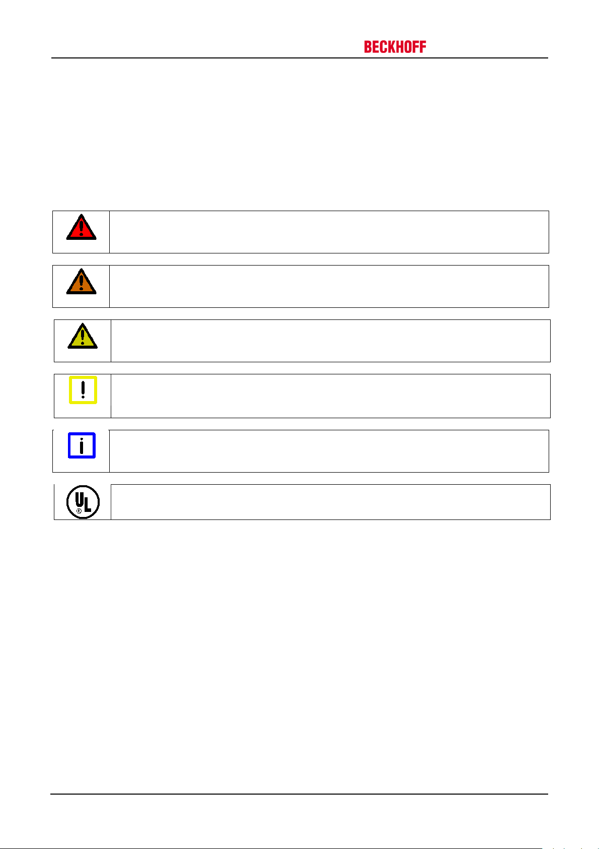
3.1.2 Description of safety symbols
The following safety symbols and associated safety instructions are used in this document. These safety
instructions must be read and followed.
Serious risk of injury!
Failure to follow the safety instructions associated with this symbol directly endangers the life
and health of persons.
Caution – Risk of injury!
Failure to follow the safety instructions associated with this symbol endangers the life and
health of persons.
Personal injuries!
Failure to follow the safety instructions associated with this symbol can lead to injuries to
persons.
Damage to the environment or devices!
Failure to follow the safety instructions associated with this symbol can lead to damage to the
environment or equipment.
Tip or pointer
This symbol indicates information that contributes to better understanding.
UL note
This symbol indicates important information regarding UL certification.
10 Version: 1.5 AM3000 / AM3500
Page 11
Drive Technology 3 Safety
3.2 Special safety instructions for AM3000 and AM3500
The safety instructions are designed to avert danger and must be followed during installation, commissioning,
production, troubleshooting, maintenance and trial or test assemblies.
The servomotors of the AM3000 and AM3500 series are not designed for stand-alone operation and are always
installed in a machine or system. After installation the additional documentation and safety instructions provided
by the machine manufacturer must be read and followed.
Serious risk of injury through high electrical voltage!
• Never open the servomotor when it is live. The measured voltage between terminals U, V
WARNING
and W must have dropped below 50 V. Opening the device would invalidate any warranty
and liability claims against Beckhoff Automation GmbH & Co. KG.
• Negligent, improper handling of the servomotor and bypassing of the safety devices can lead
to personal injury or death through electric shock.
• Ensure that the protective conductor is connected properly.
• The machine manufacturer must prepare a hazard analysis for the machine, and must take
appropriate measures to ensure that unexpected movements can not lead to injury to
persons or to material damage.
• Power leads may be live, even if the motor is not running. Never undo the electrical
connections to the motor when it is live. Under unfavourable conditions arcing may occur,
resulting in injury and damage to contacts.
WARNING
Attention
• Disconnect the servomotor from the servo drive and secure it against reconnection before
working on electrical parts with a voltage > 50 V.
• The DC link voltage of the servo drive may exceed 890 V. Wait until the DC link capacitors
are discharged before touching live terminals. The measured voltage between terminals DC+
and DC- (X02) must have dropped below 50 V.
Serious risk of injury through hot surfaces!
• The surface temperature may exceed 50 °C, resulting in a risk of burns.
• Avoid touching the housing during or shortly after operation.
• Leave the servomotor to cool down for at least 15 minutes after it is switched off.
• Use a thermometer to check whether the surface has cooled down sufficiently.
Danger for persons, the environment or equipment
• Carefully read this manual before using the servomotor thoroughly, paying particular
attention to the safety instructions. In the event of any uncertainties please notify your sales
office immediately and refrain from working on the servomotor.
• Only well trained, qualified electricians with sound knowledge of drive equipment may work
on the device.
• During installation it is essential to ensure that the specified ventilation clearances and
climatic conditions are adhered to. Further information can be found in the "Technical data"
and "Mechanical installation" sections.
• If a servomotor is installed in a machine it must not be commissioned until proof of
compliance of the machine with the latest version of the EC Machinery Directive has been
provided. This includes all relevant harmonised standards and regulations required for
implementation of this Directive in national legislation.
AM3000 / AM3500 Version: 1.5 11
Page 12

4 Handling
AM301x
X
10
AM302x
X
10
AM303x
X 6 AM304x
X 6 AM305x
X 5 AM306x
X 1 AM307x
X 1 AM308x
X
1
Attention
Drive Technology
4 Handling
4.1 Transport
• Climate category: 2K3 according to EN 50178
• Transport temperature: -25 °C - +70 °C, max. fluctuation 20 K/hour
• Transport humidity: relative humidity 5% - 95%, non-condensing
• The servomotor may only be transported by qualified personnel and in the manufacturer's original recyclable
packaging.
• Avoid hard impacts, particularly at the shaft end.
• If the packaging is damaged, check the motor for visible damage. Inform the transport company and, if
necessary, the manufacturer.
4.2 Packaging
• Cardboard packaging with Instapak
• You can return the plastic portion to the supplier (see Disposal)
Motor type Carton Max. stacking height
®
foam cushion.
4.3 Storage
• Climate category 1K4 according to EN50178
• Storage temperature: -25 °C - +55 °C, max. fluctuation 20 K/hour
• Air humidity: relative humidity 5% - 95%, non-condensing
• Max. stacking height: see table Packaging
• Storage time: without limitation
• Store only in the manufacturer’s original recyclable packaging
4.4 Maintenance / Cleaning
• Maintenance and cleaning only by qualified personnel.
• The ball bearings have a grease filling with a service life of 20,000 hours under normal operating conditions.
The bearings should be replaced after 20,000 hours of operation under rated conditions.
• Check the motor for bearing noise every 2,500 operating hours or once per year. If any noises are heard,
stop the operation of the motor. The bearings must be replaced.
• Opening the motor invalidates the warranty.
• Clean the housing with isopropanol or similar.
Destruction of the servomotor
Never immerse or spray the servomotor.
12 Version: 1.5 AM3000 / AM3500
Page 13

Drive Technology 4 Handling
4.5 Disposal
• In accordance with the WEEE 2002/96/EC Directives we take old devices and accessories back for
professional disposal, provided the transport costs are taken over by the sender. Please send the devices
to:
Beckhoff Automation GmbH & Co. KG
Eiserstrasse 5
33415 Verl
Germany
AM3000 / AM3500 Version: 1.5 13
Page 14
5 Product identification
BECKHOFF
Type
SN Art.No.
Mo
Nm
Udc
V
Iso. cl.
Nn
r/min
In A IP
Made in EU
Flange size
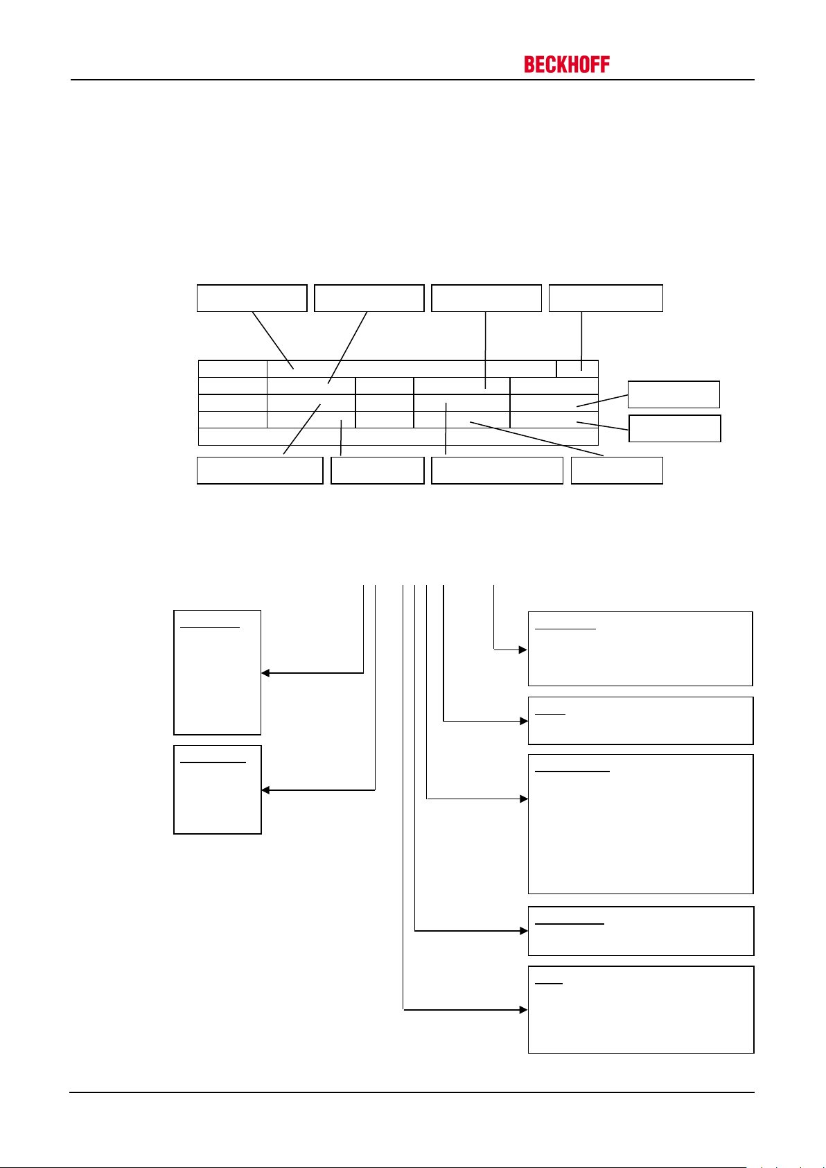
8 = 250 mm
Rotor length
5
Feedback unit
8 SKM multi turn
Winding type
S = special winding
Shaft
5 food industry
AM30 6 2 – 0 P 0 1 – 0000
Servomotor type
Serial number
Item number
Date of manufacture
Standstill torque
Nominal speed
DC link voltage
Rated current
Insulation class
Brake
1 24 V holding brake
Connection
6 terminal box
Protection class
5 Product identification
5.1 AM3000, scope of supply
Please check that the delivery includes the following items:
• Motor from the AM3000 series
• Motor package leaflet (short info)
5.2 AM3000 nameplate
5.3 AM3000 type key
Drive Technology
1 = 40 mm
2 = 58 mm
3 = 70 mm
4 = 84 mm
5 = 108 mm
6 = 138 mm
7 = 188 mm
0 rotatable angular connectors
1 0.5 m cable with connector
5 yTec connector
0 none brake
1
2
3
4
0 resolver, 2-pole
1 EnDAT single turn
2 EnDAT multi turn
3 BISS single turn
4 BISS multi turn
5 EQI single turn
6 EQI multi turn
7 SKS single turn
A…Z
0 smooth shaft
1 feather key groove
2 sealing ring – smooth shaft
3 sealing ring – feather key groove
14 Version: 1.5 AM3000 / AM3500
Page 15
BECKHOFF
Type
SN Art.No.
Mo
Nm
Udc V Iso. cl.
Nn
r/min
In A IP
Made in EU
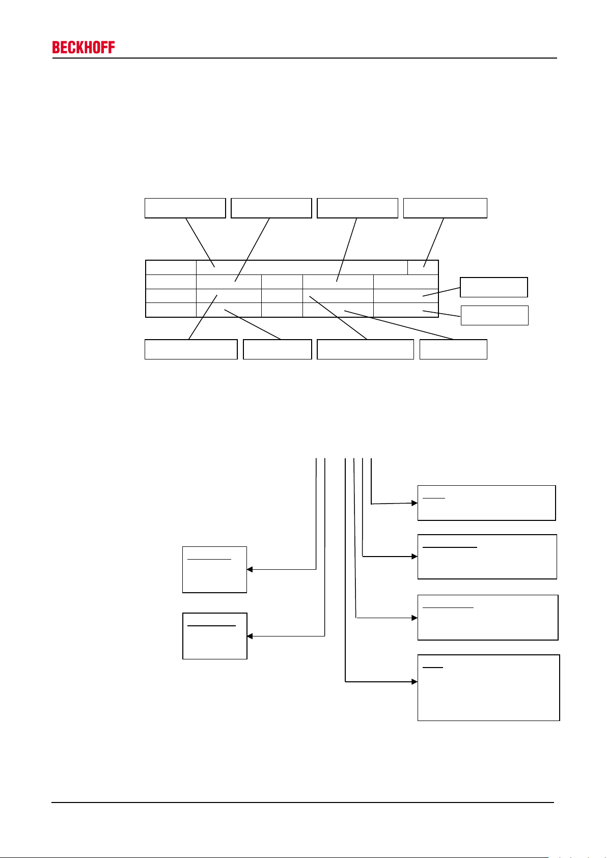
Flange size
6 138 mm
Rotor length
3
Brake
1 24V holding brake
Feedback unit
4 BISS multi turn
Winding type
9 special winding
Shaft
groove
AM35 4 1 – 0 0 0 1
Servomotor type
Serial number
Item number
Date of manufacture
Standstill torque
Nominal speed
DC link voltage
Rated current
Insulation class
Protection class
Drive Technology 5 Product identification
5.4 AM3500, scope of supply
Please check that the delivery includes the following items:
• Motor from the AM3500 series
• Motor package leaflet (short info)
5.5 AM3500 nameplate
5.6 AM3500 type key
4 84 mm
5 108 mm
1
2
0 without brake
0 Resolver
3 BiSS single turn
0 3000 min-1
1 6000 min
0 smooth shaft
1 feather key groove
2 sealing ring – smooth shaft
3 sealing ring – feather key
-1
AM3000 / AM3500 Version: 1.5 15
Page 16

6 Technical description
3K3 according to EN 50178
+5 - +40 °C for site altitudes up to 1000 m amsl
above 40 °C and encapsulated installation of the motors.
95% relative humidity, non-condensing
For site altitudes above 1000 m amsl and 40 °C
reduction of 10K / 1000m
=20,000 operating hours
→ see Section 10
→ see Section 4
Drive Technology
6 Technical description
6.1 Design of the motors
The synchronous servomotors of the AM3000 and AM3500 series are brushless three-phase motors for
demanding servo-applications. In conjunction with our digital servo drives they are particularly suitable for
positioning tasks in industrial robots, machine tools, transfer lines etc. with demanding requirements in terms of
dynamics and stability.
The servomotors are equipped with permanent magnets in the rotor. This advanced neodymium magnetic
material makes a significant contribution to the motors' exceptional dynamic properties. A three-phase winding
is housed in the stator, and this is powered by the servo drive. The motor has no brushes, the commutation
being implemented electronically in the servo drive.
The temperature of the winding is monitored by temperature sensors in the stator windings and is signalled via
an electrically isolated thermistor (PTC, _550 Ω / _1330 Ω).
The motors normally have an integrated resolver to provide feedback. Beckhoff servo drives analyse the
resolver position of the rotor and supply the motors with sine currents. The optional feedback systems may
require modification of the motor length and cannot be retrofitted.
The motors are available with or without built-in holding brake. The brake cannot be retrofitted.
The motors have a matt black coating (RAL 9005). The finish is not resistant against solvents (e.g.
trichlorethylene, thinners or similar). The “Washdown”-model is white coated and FDA (Food and Drug
Administration) conform.
6.2 General technical data
Climate category
Ambient temperature
(at rated values)
Permissible humidity
(at rated values)
Power derating
(currents and torques)
Ball bearing service life
Technical data
Storage and transport data
It is vital to consult our applications department for ambient temperatures
6% at 2000 m amsl
17% at 3000m amsl
30% at 4000m amsl
55% at 5000m amsl
No derating for site altitudes above 1000 m amsl with temperature
16 Version: 1.5 AM3000 / AM3500
Page 17
Drive Technology 6 Technical description
6.3 Standard features
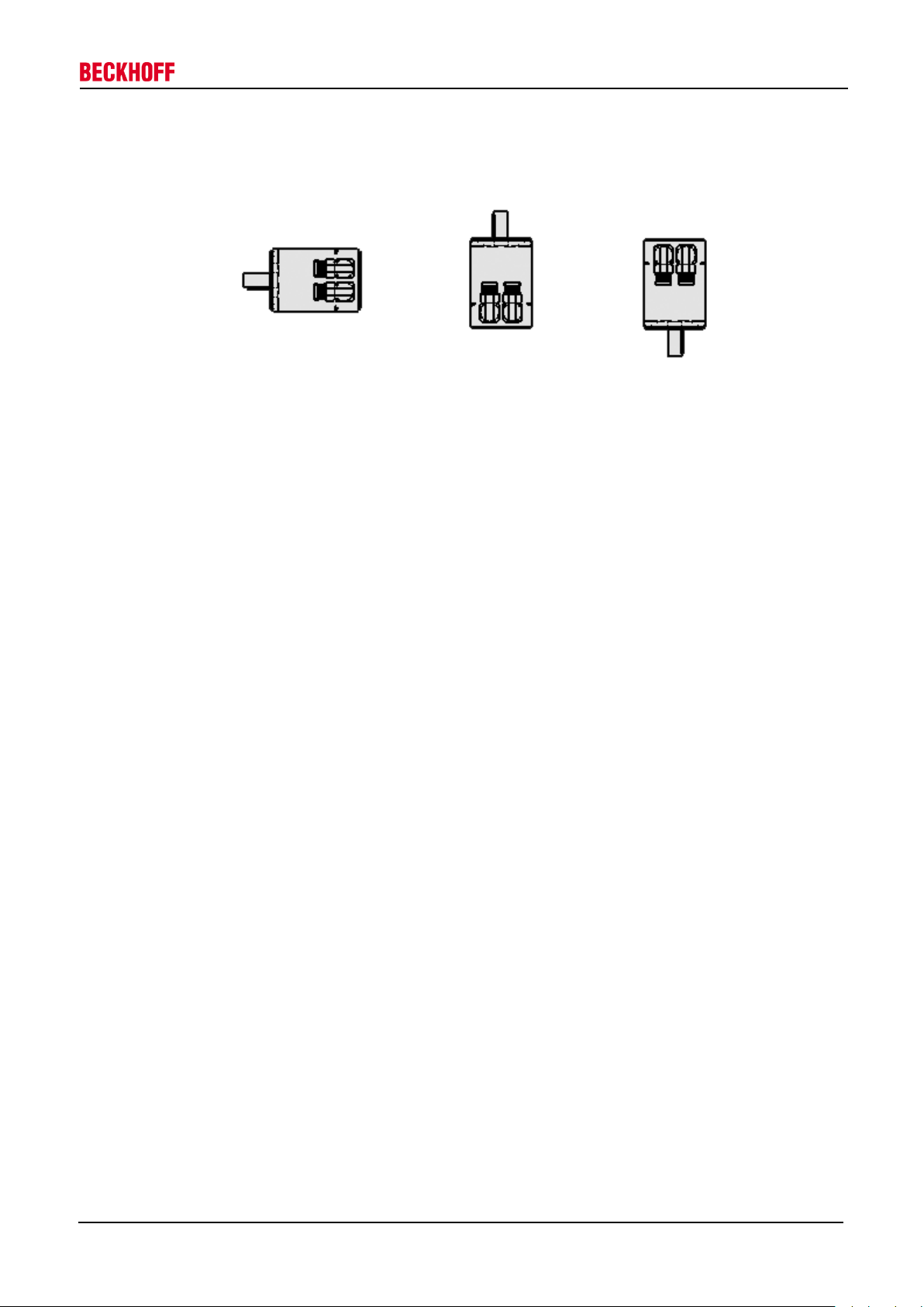
6.3.1 Style
The basic style for the AM3000 and AM3500 synchronous servomotors is IM B5 according to DIN EN 60034-7.
IM B 5 (B5) IM V 3 (V3) IM V 1 (V)
The permitted mounting positions are specified in the technical data.
6.3.2 Shaft end, A-side
Power transmission is made through the cylindrical shaft end A, fit k6 (AKM1: h7) according to EN 50347, with
a locking thread or optionally with a feather key groove. The bearings are designed for a service life of 20,000
hours.
Radial force
If the motors drive via pinions or toothed belts, then high radial forces will occur. The permissible values at the
shaft end, depending on the speed, may be read from the diagrams in the Section 10. The permissible
maximum values can be found in the technical data. Power take-off from the middle of the free end of the shaft
allows a 10% increase in FR.
Axial force
Axial forces arise when assembling pinions or pulleys on the shaft and using angular gearheads, for example.
The permissible maximum values can be found in the technical data.
Coupling
Double-coned collets, possibly in association with metal bellows couplings, have proven themselves as
excellent, zero backlash coupling elements.
6.3.3 Flange
Flange dimensions according to IEC standard, fit j6 (AM301x: h7), accuracy according to DIN 42955
Tolerance class: N
6.3.4 Protection class
Standard version IP65
Standard shaft bushing IP54
Shaft bushing with shaft sealing ring IP67
6.3.5 Overtemperature protection
The standard version of each motor is fitted with an electrically isolated PTC with a rated temperature of 155 °C
± 5%. The PTC does not provide any protection against short, heavy overloading.
Provided that our preassembled cable is used, the PTC is integrated into the monitoring system of the digital
servo drives.
6.3.6 Insulation material class
The motors conform to insulation material class F according to IEC 60085 (UL 1446 class F).
AM3000 / AM3500 Version: 1.5 17
Page 18
6 Technical description
<= 1800
90
23
> 1800
65
16
Resolver
Two-pole, hollow shaft
EnDAT Encoder, Singleturn
AM302x-AM304x: ECN 1113,
AM305x-AM307x: EQN 1325
EnDAT Encoder, Multiturn
AM302x-AM304x: EQN 1125
AM305x-AM307x: EQN 1325
BiSS Encoder, Single- / Multiturn
AM302x-AM304x: AD36
AM305x-AM307x: AD58
BiSS Encoder, Single- / Multiturn
AM35xx: AD34
Note
WARNING
Note
Drive Technology
6.3.7 Vibration class
The motors are made to vibration class A according to DIN EN 60034-14. For a speed range of 600-3600 rpm
and a shaft centre height between 56-132 mm, this means that the actual value of the permitted vibration
severity is 1.6 mm/s.
Speed [rpm] Max. rel. vibration
displacement [µm]
Max. run-out [µm]
6.3.8 Connection technology
The motors are fitted with angular connectors (AM301x: straight connectors at the cable ends) for the power
supply and the feedback signals.
The mating connectors are not included in the scope of supply. We can supply preassembled feedback and
power cables. Information regarding the cable materials can be found in Section 8.2.
6.3.9 Feedback unit
Standard
Option
Option
Option
Option
Motor length
The motor length depends on the built-in feedback unit, among other factors. Retrofitting is not
possible.
6.3.10 Holding brake
Serious risk of injury!
The holding brake is not personal safety. If the brake is released then the rotor can be moved
without a remanent torque!
The AM302x-AM308x and AM35xx motors are optionally available with an in-built holding brake. The AM3000
model features a spring-actuated brake (24 V DC), the AM3500 features a permanent-magnet brake (24 V DC).
When the brake is de-energised it blocks the rotor. The holding brakes are designed as standstill brakes
and are not suited for repeated operational braking.
The holding brakes can be controlled directly by the servo drive (no personal safety!), in which case the brake
winding is suppressed in the servo drive. Additional circuitry is not required.
If the holding brake is not controlled directly by the servo drive, additional circuitry (e.g. varistor) is required.
Consult our applications department beforehand.
Motor length
The motor length depends on the built-in holding brake, among other factors. It is not possible to
fit one at a later date.
18 Version: 1.5 AM3000 / AM3500
Page 19
AM301x
6
AM304x
10
AM307x
10
AM354x
10
AM302x
6
AM305x
10
AM308x
10
AM355x
10
AM303x
8
AM306x
10
AM356x
10
data.
Drive Technology 6 Technical description
6.3.11 Pole numbers
Motor Poles Motor Poles Motor Poles Motor Poles
6.4 Options
Holding brake
The holding brake is integrated in the motor. It increases the motor length.
Radial shaft-sealing ring
Radial shaft-sealing ring (Teflon) for sealing against oil mist and oil spray. This increases the protection class of
the shaft bushing to IP67.
Feather key
The motors are available with feather key groove and fitted feather key according to DIN6885. The rotor is
balanced with half a feather key.
EnDat (only AM30xx), BiSS
This model features a different feedback system in place of the resolver, which may result in an increase of the
motor length.
Installation options and reduction of rated values
With the exception of the sealing ring, the options cannot be retrofitted.
Note
Options such as sealing ring, holding brake, EnDAT or BiSS can lead to a reduction of the rated
6.5 Selection criteria
The three-phase servomotors are designed for operation with servo drives.
Both units together form a speed or torque control loop.
The main selection criteria are:
— Standstill torque M0 [Nm]
— Rated speed at rated supply voltage nn [min-1]
— Moment of inertia of motor and load J [kgcm²]
— Effective torque (calculated) Mrms [Nm]
The static load and the dynamic load (acceleration/braking) must be taken into account in the calculation of the
required motors and servo drives. Formulas and calculation example are available from our applications
department on request.
AM3000 / AM3500 Version: 1.5 19
Page 20
7 Mechanical installation
2
0
min
x
F
M
dR≥
7 Mechanical installation
7.1 Important notes
Destruction of the motors
• Protect the motors from unacceptable stresses. Take care, especially during transport and
Attention
handling, that components are not bent and that insulation clearances are not altered.
• The site must be free of conductive and aggressive material. For V3-mounting (shaft end
upwards), make sure that no liquids can enter the bearings. If an encapsulated assembly is
required, please consult our applications department beforehand.
• Ensure unhindered ventilation of the motors and observe the permissible ambient and flange
temperatures. For ambient temperatures above 40 °C please consult our applications
department beforehand.
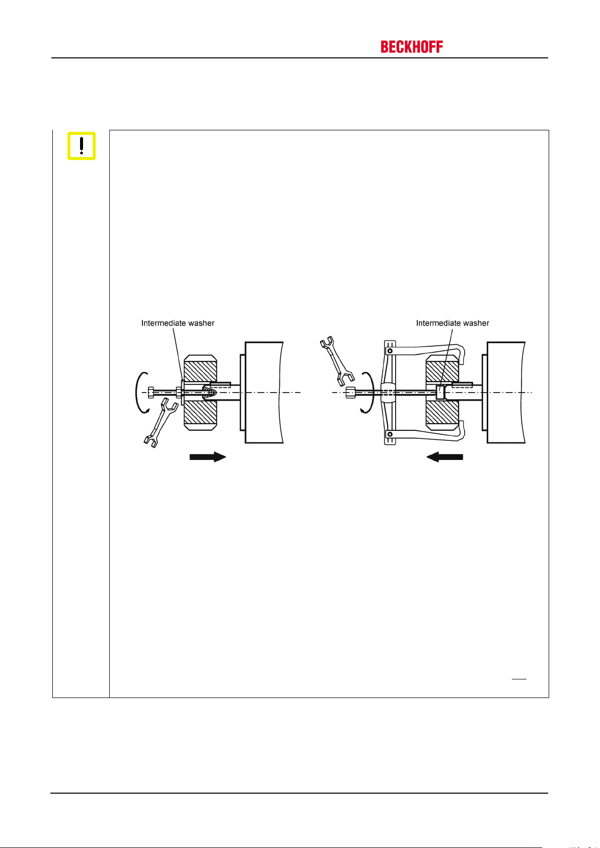
• Servomotors are precision devices. The flange and shaft are especially vulnerable during
storage and assembly. It is important to use the locking thread which is provided to tighten
up couplings, gear wheels or pulleys and warm up the drive components, where possible.
Blows or the use of force will lead to damage to the ball bearings and the shaft.
Drive Technology
• Wherever possible, use only backlash-free, frictionally-locking collets or couplings. Ensure
correct alignment of the couplings. A displacement will cause unacceptable vibration and the
destruction of the ball bearings and the coupling.
• For toothed belts, it is vital to observe the permissible radial forces. An excessive radial load
on the shaft will significantly shorten the life of the motor.
• Avoid axial loads on the motor shaft, as far as possible. Axial loading significantly shortens
the life of the motor.
• In any case, avoid creating a mechanically constrained motor shaft mounting by using a rigid
coupling with additional external bearings (e.g. in a gearbox).
• Take note of the no. of motor poles and the no. of resolver poles and ensure that the correct
setting is made in the used servo drives. An incorrect setting can lead to the destruction of
the motor, especially with small motors.
• Check compliance the permitted radial and axial loads F
drive, the minimum permitted diameter of the pinion follows from the equation:
and FA. When using a toothed belt
R
20 Version: 1.5 AM3000 / AM3500
Page 21

Connect the motor holding brake
Drive Technology 8 Electrical installation
8 Electrical installation
8.1 Important notes
Serious risk of injury through electric shock!
• Only staff qualified and trained in electrical engineering are allowed to wire up the motor.
DANGER
Attention
• Check the assignment of the servo drive and the motor. Compare the rated voltage and the
rated current of the devices.
• Always make sure that the motors are de-energised during assembly and wiring, i.e. no
voltage may be switched on for any piece of equipment which is to be connected. Ensure
that the control cabinet remains turned off (barrier, warning signs etc.). The individual
voltages will only be turned on again during commissioning.
• Never undo the electrical connections to the motor when it is live. A dangerous voltage,
resulting from residual charge, can be still present on the capacitors up to 5 minutes after
switch-off of the mains supply.
Measure the DC link voltage and wait until it has fallen below 40 V.
Control and power leads may be live, even if the motor is not running.
Smooth operation
• Ensure that there the servo drive and the motor are earthed properly. See below for further
information regarding EMC shielding and earthing. Earth the mounting plate and motor
housing. Further details of connection types can be found in Section 8.2
Attention
Note
• Route the power and control cables as separately as possible from one another (separation
> 20 cm). This will improve the immunity of the system to electromagnetic interference. If a
motor power cable is used which includes integral brake control leads, then these brake
control leads must be shielded. The shielding must be connected at both ends (see below).
• Install all cables carrying a heavy current with an adequate cross-section, as per EN 60204.
The recommended cross-section can be found in the technical data.
• Wiring:
Connect the resolver or encoder
Connect the motor cables
Connect shields to shield terminals or EMC connectors at both ends
Connect the temperature contact
HF interference
• The ground symbol , which you will find in the wiring diagrams, indicates that you must
provide an electrical connection, with as large a surface area as possible, between the unit
indicated and the mounting plate in the control cabinet. This connection is to suppress HF
interference and must not be confused with the PE (protective earth) symbol (protective
measure according to EN 60204).
Follow the instructions in the circuit diagrams in Sections 8.3 to 8.6
Long motor cables
• In case of long motor cables (>25m) a motor choke must be provided between the motor and
the servo drive.
AX2000 / AX2500: Connect up all shielding via a wide surface-area contact (low impedance)
and metallised connector housings or EMC cable glands. Install the motor choke close to the
servo drive.
AX5000: The motor choke is supplied with a connection cable. Do not alter the configuration
(cable length, cross-section etc.).
AM3000 / AM3500 Version: 1.5 21
Page 22

8 Electrical installation
Specification
4 x 1.5 mm2 + 2 x (2 x 0.75 mm2)
General data
Weight
kg / km
Min. bending radius
203 mm
Overall diameter
11.3 mm +/- 4%
Max. velocity
180 m/min
Max. acceleration
5 m/s2
Max. no. of cycles
50.000
Max. tensile load
20 N/mm2
Operating temperature
-10 to 80 °C
Standards and features
UL AWM listed
80 °C – 1000 V
CSA AWM listed
75 °C – 1000 V
VDE (U0 / U)
0.6/1 kV
Flame resistance
DIN EN 50265-2-1
Oil resistance
UL 1581
Silicone-free
yes
CFC-free
yes
Halogen-free
no
Sheath
Material
PVC according to UL AWM & CSA AWM
Shielding
tinned copper braid, optical cover ≥ 85%
Separator
Polyester strap
Colour
RAL 2003 (orange)
Power leads
4 x 1.5 mm2
Conductor material
blank copper cl.5 (DIN EN 60228; VDE 0295; IEC
60228)
Insulation
TEO Flexene ® polymer compound, compliant
with UL AWM & CSA AWM
Colour code
black (1 -3) + green/yellow
Signal leads
2 x (2 x 0.75 mm2)
Conductor material
blank copper cl. 5 (DIN EN 60228; VDE 0295; IEC
60228)
Insulation
TEO Flexene ® polymer compound, compliant
with UL AWM & CSA AWM
Structure
pair-wise twisted
Shielding per pair
tinned copper sheath, optical cover ≥ 85%
Separator
fleece tape
Colour code for signal pairs
2 pairs
Drive Technology
8.2 Connection of motors with pre-assembled cables
Beckhoff offers preassembled motor and feedback cables for safe, faster and flawless installation of the
motors. Beckhoff cables have been tested with regard to the materials, shielding and connectors used. They
ensure proper functioning and compliance with statutory regulations such as EMC, UL etc. The use of other
cables may lead to unexpected interference and invalidate the warranty.
• Carry out the wiring in accordance with the valid standards and regulations.
• Only use our preassembled shielded cables for the power and feedback connections.
• Connect up the shielding according to the wiring diagrams in sections 8.3 to 8.6. Incorrectly installed
shielding inevitably leads to EMC interference.
All available cable types are listed below. Should you require additional information please contact our support.
8.2.1 AX5000
All cables are UL-listed.
8.2.1.1 Cables for fixed installation
Motor cable with signal line
22 Version: 1.5 AM3000 / AM3500
Page 23

1st pair
black and black (5-6)
2nd pair
black and black (7-8)
Electrical specifications
Test conditions
20 °C
Test voltage for power
Requirement
Operating voltage
≤1000 V
Conductor resistance
IEC 60228 Cl.5
Insulation resistance
≥2500 MOhm x km
Capacitance:
Signals
max. 100 pF / m
Specification
Encoder cable
7x(2x0.14mm2)+1x(2x0.5mm2)
Reserved
General data
Weight
kg / km
Min. bending radius
137 mm
Overall diameter
7.6 mm +/- 0.3 mm
Max. velocity
180 m / min
Max. acceleration
5 m / s2
Max. no. of cycles
50.000
Max. tensile load
20 N / mm2
Operating temperature
-10 to 80 °C
Standards and features
UL AWM listed
80 °C – 30 V
CSA AWM listed
75 °C – 30 V
Flame resistance
DIN EN 50265-2-1
Oil resistance
UL 1581
Silicone-free
yes CFC-free
yes Halogen-free
no
Sheath
Material
PVC according to UL AWM & CSA AWM
Shielding
tinned copper braid, optical cover ≥ 85%
Separator
Polyester strap
Colour
RAL 6018 (green)
Signal leads
7 x (2 x 0.14 mm2)
Conductor material
Conductor resistance
tinned copper 7x0.16 mm
≤140 Ohm / km
Insulation
polypropylene compliant with UL AWM & CSA AWM
Structure
pair-wise twisted
Colour code for signal
pairs
1st pair
brown and white
2nd pair
green and yellow
3rd pair
grey and pink
4th pair
red and blue
5th pair
black and violet
Drive Technology 8 Electrical installation
Encoder cable
leads
(conductor/conductor conductor/shielding)
Test voltage for signal
leads
(conductor/conductor conductor/shielding)
Power
4 kV eff. 5 min.
2 kV eff. 1 min.
undamaged insulation
max. 150 pF / m
AM3000 / AM3500 Version: 1.5 23
8 pairs
Page 24

8 Electrical installation
6th pair
grey/pink and red/blue
7th pair
white/green and brown/green
8th pair
white/yellow and yellow/brown
Electrical specifications
Test conditions
20 °C
Test voltage
Requirement
Operating voltage
≤ 30 V
Conductor material
Conductor resistance
2 x 0.5 mm², tinned copper 19 x 0.18 mm
0.5 mm2 ≤ 40 Ohm / km
Insulation resistance
min. 2500 MOhm x km
Capacitance:
Signals
max. 120 pF / m
Specification
4 x 1.5 mm2 + 2 x (2 x 0.75 mm2)
General data
Weight
kg / km
Min. bending radius
85 mm
Overall diameter
12.2 mm E 4mm
Max. velocity
240 m / min
Max. acceleration
30 m / s2
Max. no. of cycles
10 million
max. horizontal length
20 m
max. vertical length
5 m
Max. tensile load
20 N / mm2
Operating temperature
-10 to 80 °C
Standards and features
UL AWM listed
80 °C – 1000 V
CSA AWM listed
75 °C – 1000 V
VDE (U0 / U)
0.6 / 1 kV
Flame resistance
DIN EN 50265-2-1
Oil resistance
UL 1581
Silicone-free
yes
CFC-free
yes
Halogen-free
yes
Sheath
Material
TMPU, halogen-free, compliant with UL AWM &
CSA AWM
Shielding
tinned copper braid, optical cover ≥ 85%
Separator
Polyester strap
Colour
RAL 2003 (orange)
Power leads
4 x 1.5 mm2
Conductor material
blank copper cl.5 (DIN EN 60228; VDE 0295; IEC
60228)
Insulation
TEO Flexene ® polymer compound, compliant
with UL AWM & CSA AWM
Colour code
black (1 -3) + green/yellow
Signal leads
2 x (2 x 0.75 mm2)
Conductor material
blank copper cl. 5 (DIN EN 60228; VDE 0295; IEC
60228)
Insulation
TEO Flexene ® polymer compound, compliant
with UL AWM & CSA AWM
Drive Technology
(conductor/conductor conductor/shielding)
Power
8.2.1.2 Cables for flexible installation / highly dynamic operation
Motor cable with signal line
1500 VDC
undamaged insulation
max. 100 pF / m
24 Version: 1.5 AM3000 / AM3500
Page 25

Structure
pair-wise twisted
Shielding per pair
tinned copper sheath, optical cover ≥ 85%
Separator
fleece tape
Colour code for signal pairs
2 pairs
1st pair
black and black (5-6)
2nd pair
black and black (7-8)
Electrical specifications
Test conditions
20 °C
Test voltage for power
Requirement
Operating voltage
≤ 1000 V
Conductor resistance
IEC 60228 Cl.5
Insulation resistance
≥ 2500 MOhm x km
Capacitance:
Signals
max. 100 pF / m
Specification
Encoder cable
7x(2x0.14mm2)+1x(2x0.5mm2)
Reserved
General data
Weight
kg / km
Min. bending radius
53 mm
Overall diameter
7.6 mm ± 0.3 mm
Max. velocity
240 m / min
Max. acceleration
30 m / s2
Max. no. of cycles
10 million
max. horizontal length
20 m
max. vertical length
5 m Max. tensile load
20 N/mm2
Operating temperature
-10 to 80 °C
Standards and features
UL AWM listed
80 °C – 30 V
CSA AWM listed
75 °C – 30 V
Flame resistance
DIN EN 50265-2-1
Oil resistance
UL 1581
Silicone-free
yes CFC-free
yes Halogen-free
yes Sheath
Material
TMPU, halogen-free, compliant with UL AWM & CSA
AWM
Shielding
tinned copper braid, optical cover ≥ 85%
Separator
Polyester strap
Colour
RAL 6018 (green)
Signal leads
7 x (2 x 0.14 mm2)
Conductor material
Conductor resistance
tinned copper 7 x 0.16 mm
≤140 Ohm / km
Insulation
polypropylene compliant with UL AWM & CSA AWM
Structure
pair-wise twisted
Drive Technology 8 Electrical installation
Encoder cable
leads
(conductor/conductor conductor/shielding)
Test voltage for signal
leads
(conductor/conductor conductor/shielding)
Power
4 kV eff. 5 min.
2 kV eff. 1 min.
undamaged insulation
max. 150 pF / m
AM3000 / AM3500 Version: 1.5 25
Page 26

8 Electrical installation
Colour code for signal
pairs
1st pair
brown and white
2nd pair
green and yellow
3rd pair
grey and pink
4th pair
red and blue
5th pair
black and violet
6th pair
grey/pink and red/blue
7th pair
white/green and brown/green
8th pair
white/yellow and yellow/brown
Electrical specifications
Test conditions
20 °C
Test voltage
Requirement
Operating voltage
≤ 30 V
Conductor material
Conductor resistance
2 x 0.5 mm², tinned copper 19 x 0.18 mm
≤ 40 Ohm / km
Insulation resistance
min. 2500 MOhm x km
Capacitance:
Signals
max. 120 pF / m
Specification
AX2000
4 x 1.5 mm2 + 2 x 1 mm2
AX2500
4 x 1 mm2 + 2 x 1 mm2
General data
Min. bending radius
118 mm
115 mm
Weight
185 kg / km
155 kg / km
Overall diameter
10.6 mm ± 4 %
10 mm ± 4 %
Max. velocity
120 m / min
Max. acceleration
4 m / s2
Max. no. of cycles
10 million
Max. tensile load
static / dynamic
Operating temperature
0 to 80 °C
Oil resistance
“VDE 0472 Part 803 B”; “VDE 0282 Part 10”;
“UL 1581”
Sheath
Material
PUR according to the UL standard
Shielding
tinned copper braid, optical cover ≥ 85%
Colour
RAL 2003 (orange)
Power leads
4 x 1.5 mm2
4 x 1 mm2
Conductor material
blank copper (DIN EN 60228; VDE 0295; IEC
60228)
Insulation
polyolefin polymer according to the
UL standard
Signal leads
2 x 1 mm2
Conductor material
blank copper (DIN EN 60228; VDE 0295; IEC
60228)
Insulation
polyolefin polymer according to the
UL standard
Shielding
tinned copper sheath, optical cover ≥ 85%
Electrical specifications
8 pairs
Drive Technology
(conductor/conductor conductor/shielding)
Power
1500 VDC
undamaged insulation
max. 100 pF / m
8.2.2 AX2000 and AX2500
All cables are specified for flexible routing. They enable highly dynamic operation and are UL-listed.
Motor cable with signal line
26 Version: 1.5 AM3000 / AM3500
50 / 20 N / mm2
Page 27

Test conditions
20 °C
Test voltage for power leads
Requirement
Operating voltage
≤ 1000 V
Conductor resistance
Signal leads
20.5 Ohm / km
Shielding resistance
Signal leads
50 Ohm / km
Insulation resistance
Signal leads
min. 20 MOhm x km
Capacitance
Signal leads
max. 150 pF / m
Specification
Encoder cable
8 x 2 x 0.14 mm2
Resolver cable
4 x 2 x 0.25 mm2
General data
Weight
69 kg / km
80 kg / km
Min. bending radius
75 mm
Overall diameter
7.5 mm +/- 4%
Max. velocity
120 m / min
Max. acceleration
4 m / s2
Max. no. of cycles
10 million
Max. tensile load
static / dynamic
Operating temperature
0 to 80 °C
Oil resistance
“VDE 0472 Part 803 B”; “VDE 0282 Part 10”; “UL
1581”
Sheath
Material
PUR according to the UL standard
Shielding
tinned copper braid, optical cover ≥ 85%
Colour
RAL 6018 (green)
Signal leads
8 x 2 x 0.14 mm2
4 x 2 x 0.25 mm2
Conductor material
blank copper (DIN EN 60228; VDE 0295; IEC
60228)
Insulation
polyolefin polymer according to the
UL standard
Structure
pair-wise twisted
Colour code for signal pairs
8 pairs
4 pairs
1st pair
brown and white
2nd pair
green and yellow
3rd pair
grey and pink
4th pair
red and blue
5th pair
black and violet
---
6th pair
grey/pink and red/blue
---
7th pair
white/green and
brown/green
8th pair
white/yellow and
yellow/brown
Electrical specifications
Test conditions
20 °C
Drive Technology 8 Electrical installation
(conductor/conductor conductor/shielding)
Test voltage for signal leads
(conductor/conductor conductor/shielding)
Test period
Power leads
Power leads
Encoder and resolver cable
3 kV eff.
1.5 kV
5 min.
undamaged insulation
min. 5000 MOhm x km
max. 120 pF / m
50 / 20 N / mm2
---
---
AM3000 / AM3500 Version: 1.5 27
Page 28

8 Electrical installation
Test voltage for signal
Requirement
Operating voltage
300 V
Insulation resistance
Signal leads min. 5000 MOhm x km
Capacitance
max. 120 pF / m
Drive Technology
leads
(conductor/conductor conductor/shielding)
Test period
1.5 kV eff.
5 min.
undamaged insulation
28 Version: 1.5 AM3000 / AM3500
Page 29

Drive Technology 8 Electrical installation
8.3 AX5000 connection diagram for motors with EnDAT / BiSS encoder
Power connector Motor cable
8-poles, round ZK4500-xxxx-xxxx
Power
Encoder connector Encoder cable
17-poles, round ZK4510-xxxx-xxxx
D-Sub 15 poles
Thermal protection contact and brake
AM3000 / AM3500 Version: 1.5 29
Page 30

8 Electrical installation
Power
Drive Technology
8.4 AX5000 connection diagram for motors with resolver
Thermal protection contact and brake
Power connector Motor cable
8-poles, round ZK4500-xxxx-xxxx
Resolver connector Resolver cable
12-poles, round ZK4530-xxxx-xxxx
D-Sub 15 poles
30 Version: 1.5 AM3000 / AM3500
Page 31

Drive Technology 8 Electrical installation
8.5 AX5000 connection diagram for motors with resolver and yTec-Plug
Brake
Power connector Motor cable
9 pol. - yTec ZK4500-0211-xxxx
Power
Resolver connector Resolver cable
12 pol. - yTec ZK4530-xxxx-xxxx
D-Sub 15 poles
AM3000 / AM3500 Version: 1.5 31
Page 32

8 Electrical installation
Encoder connector Encoder cable
8.6 AX2000 connection diagram for motors with EnDAT / BiSS encoder
17-poles, round ZK4000-xxxx-xxxx
D-Sub 15 poles
Drive Technology
32 Version: 1.5 AM3000 / AM3500
Page 33

Resolver connector Resolver cable
Drive Technology 8 Electrical installation
8.7 AX2000 connection diagram for motors with resolver
12-poles, round ZK4000-xxxx-xxxx
D-Sub 9 poles
AM3000 / AM3500 Version: 1.5 33
Page 34

9 Commissioning
9 Commissioning
9.1 Important notes
Serious risk of injury!
• Only specialist personnel with extensive knowledge in the areas of electrical engineering /
DANGER
9.2 Guide for commissioning
drive technology are allowed to install and commission the equipment.
• Check that all live connection points are protected against accidental contact. Dangerous
voltages can occur, up to 900 V.
• Never undo the electrical connections to the motor when it is live. The residual charge in the
capacitors of the servo drives can produce dangerous voltages up to 5 minutes after the
mains supply has been switched off.
• The surface temperature of the motor can exceed 100 °C in operation. Check (measure) the
temperature of the motor. Wait until the motor has cooled down below 40 °C before touching
it.
• Make sure that, even if the drive starts to move unintentionally, no danger can result for
personnel or machinery.
Drive Technology
The procedure for commissioning is described as an example.
A different method may be appropriate or necessary, depending on the application of the equipment.
• Check the assembly and orientation of the motor.
• Check the drive components (coupling, gear unit, pulley) for the correct seating and setting (observe the
permissible radial and axial forces).
• Check the wiring and connections to the motor and the servo drive. Check that the earthing is correct.
• Test the function of the holding brake, if used. (apply 24 V, the brake must be released).
• Check whether the rotor of the motor revolves freely (release the brake, if necessary). Listen out for grinding
noises.
• Check that all the required measures against accidental contact with live and moving parts have been
carried out.
• Carry out any further tests which are specifically required for your system.
• Now commission the drive according to the commissioning instructions for the servo drive.
• In multi-axis systems, individually commission each drive unit (servo drive/motor(s)).
9.3 Troubleshooting
The following table is to be seen as a “First Aid” box. There can be a large number of different reasons for a
fault, depending on the particular conditions in your system. The fault causes described below are mostly those
which directly influence the motor. Peculiarities which show up in the control behaviour can usually be traced
back to an error in the parameterisation of the servo drive. The documentation for the servo drive and the
commissioning software provides information on these matters.
For multi-axis systems there may be further hidden reasons for faults.
Our applications department can give you further help with your problems.
34 Version: 1.5 AM3000 / AM3500
Page 35

Servo drive not enabled
Supply ENABLE signal
• Motor phases in wrong
• Correct the phase sequence
Break in the shielding of the
Replace feedback cable
Short-circuit in the supply
Remove the short circuit
• Motor cable has short circuit or
• Replace motor cable
Connector is not properly
Check connector
• Motor thermostat has switched
• Wait until the motor has
• Required holding torque too
• Check the dimensioning
Drive Technology 9 Commissioning
Fault Possible cause Measures to remove the cause
of the fault
Motor doesn’t rotate
•
• Break in setpoint lead
• Motor phases in wrong
sequence
•
• Check setpoint lead
• Correct the phase sequence
Motor runs away
Motor oscillates
Error message: brake
Error message: output stage
fault
Error message: feedback
Error message: motor
temperature
• Brake not released
• Drive is mechanically blocked
sequence
•
feedback cable
• Amplification to high
•
voltage lead to the motor
holding brake
• Faulty motor holding brake
earth leakage
• Motor has short circuit or earth
leakage
•
plugged in
• Break in cable, cable crushed
or similar
• Loose connector or break in
cable
• Check brake control
• Check mechanism
•
• Use motor default values
•
• Replace motor
• Replace motor
•
• Check cables
cooled down. Then investigate
why the motor becomes so
hot.
Brake does not grip
AM3000 / AM3500 Version: 1.5 35
high
• Brake faulty
• Check connector, replace
cable if necessary
• Replace motor
Page 36

10 Technical data
Jx
cm
m
x
sxM
x
St
b
24
2
10
60
23000
][
0
π
=
Drive Technology
10 Technical data
All data valid for 40 °C ambient temperature and 100 K overtemperature of the winding.
The data can have a tolerance of +/- 10%.
10.1 Term definitions
Standstill torque M0 [Nm]
The standstill torque can be maintained indefinitely at a speed n<100 rpm and rated ambient conditions.
Rated torque M
The rated torque is produced when the motor is drawing the rated current at the rated speed.
The rated torque can be produced indefinitely at the rated speed in continuous operation (S1).
Standstill current I
The standstill current is the effective sinusoidal current which the motor draws at n<100 rpm to produce the
standstill torque.
Peak current (pulse current) I
The peak current (effective sinusoidal value) is approximately equivalent to 4-times the rated standstill current.
The peak current of the servo drive used must be smaller.
Torque constant K
The torque constant defines how much torque in Nm is produced by the motor with 1A r.m.s. current. The
relationship is M=I x K
Voltage constant K
The voltage constant defines the induced motor EMF, as an effective sinusoidal value between two terminals,
per 1000 rpm.
Rotor moment of inertia J [kgcm²]
The constant J is a measure of the acceleration capability of the motor. For instance, at I
from 0 to 3000 rpm is given as:
t
b
[Nm]
n
[A]
0rms
[Nm/A]
Trms
(up to I = 2 x I0)
T
[mVmin]
Erms
0max
[A]
the acceleration time
0
with M0 in Nm and J in kgcm2
Thermal time constant t
The constant t
defines the time for the cold motor, under a load of I0 to heat up to an overtemperature of 0.63
TH
[min]
TH
x 100 Kelvin.
This temperature rise happens in a much shorter time when the motor is loaded with the peak current.
Release delay time t
[ms] / Application delay time t
BRH
[ms] of the brake
BRL
These constants define the response times of the holding brake when operated with the rated voltage from the
servo drive.
36 Version: 1.5 AM3000 / AM3500
Page 37

Electrical data
Standstill current
I
orms
[A]
1.16
1.45
2.91
1.51
2.72
1.48
2.40
Max. mechanical speed
N
max
[min-1]
8000
Peak current
I
0max
[A]
5.8
7.3
14.6
7.6
13.6
7.4
12.0
Peak torque
M
0max
[Nm]
0.708
0.718
0.712
1.27
1.24
1.73
1.72
Voltage constant
K
Erms
[mVmin]
10.2
8.3
4.1
13.3
7.2
17.9
10.9
Winding resistance
Ph-PH
Winding inductance
Ph-Ph
Mechanical data
AM3011
AM3012
AM3013
Rotor moment of inertia
J [kgcm2]
0.017
0.031
0.045
Pole number 6 6 6
Thermal time constant
tTH [min] 4 6
7
Weight, standard
G [kg]
0.35
0.49
0.63
Permitted radial force
at shaft end
Permitted axial force
FA [N]
12
Holding torque at 120 °C
MBR [Nm]
0.41
Electrical power
PBR [W)
6.4
Application delay time
t
BRL
[ms]
30
Weight of the brake
GBR [kg]
0.20
Moment of inertia
JBR [kgcm²]
0.004
Typical backlash
[°mech.]
0.53
Drive Technology 10 Technical data
10.2 AM301x
Technical data
Standstill torque * M
Symbol
[Unit]
[Nm] 0.18 0.18 0.18 0.31 0.31 0.41 0.40
0
11B 11C 11E 12C 12E 13C 13D
AM30xx
Max. rated mains voltage UN [VAC] 230VAC
Rated speed Nn [min-1] 4000 6000 - 4000 8000 3000 7000
Rated torque * Mn [Nm] 0.18 0.18 - 0.30 0.28 0.41 0.36
U = 115V
Rated output Pn [kW] 0.08 0.11 - 0.13 0.23 0.13 0.27
Rated speed Nn [min-1] 8000 - - 8000 - 8000 -
Rated torque * Mn [Nm] 0.17 - - 0.28 - 0.36 -
= 230V
N
U
Rated output Pn [kW] 0.14 - - 0.23 - 0.30 -
Rated speed
Rated torque * Mn [Nm] - - - - - - -
= 400V
N
U
Rated output Pn [kW] - - - - - - -
[min-1] - - - - - - -
N
n
Rated speed Nn [min-1] - - - - - - -
Rated torque * Mn [Nm] - - - - - - -
= 480V
N
U
Rated output Pn [kW] - - - - - - -
Torque constant K
[Nm/A] 0.16 0.13 0.06 0.21 0.11 0.28 0.17
Trms
R25 [Ω]
18.2 12.1 3.1 12.4 3.9 13.5 5.4
L [mH] 12.5 8.3 2.0 9.1 2.7 10.3 3.8
Static friction torque MR [Nm] 0.0011 0.0021 0.0031
FR [N] 30
* reference flange aluminium 254mm x 254mm x 6.35mm
Options such as sealing ring, holding brake, EnDAT or BiSS lead to a reduction of the rated data.
Data for optional brake
Data
Supply voltage UBR [VDC] 24 ± 10 %
Release delay time t
Symbol
[Unit]
[ms] 60
BRH
Value
AM3000 / AM3500 Version: 1.5 37
Page 38

10 Technical data
Optional: Feather key
Motor type
X
Resolver
Motor type
Resolver
Encoder
Y
Z (Brake)
Y
Z (Brake)
Optional: Feather key
10.2.1A Dimensional drawing
AM3011 56.1 69.6
AM3012 75.1 88.6
AM3013 94.1 107.6
10.2.1B Dimensional drawing
Drive Technology
AM3011 79 116 88,5 125,5
AM3012 98 135 107,5 144,5
AM3013 117 154 126,5 163,5
38 Version: 1.5 AM3000 / AM3500
Page 39

Drive Technology 10 Technical data
10.2.2 Radial / axial forces at the shaft end
10.2.3 Characteristic torque / speed curves
Characteristic torque / speed curves can be found on the Beckhoff-website under Drive Technology.
AM3000 / AM3500 Version: 1.5 39
Page 40

10 Technical data
Electrical data
Standstill torque *
M0 [Nm]
0.48
0.50
0.50
0.84
0.87
0.88
1.13
1.16
1.18
1.38
1.41
1.42
Standstill current
I
orms
[A]
1.58
3.11
4.87
1.39
2.73
4.82
1.41
2.19
4.31
1.42
2.21
3.89
Max. rated mains voltage
UN [VAC]
480
Peak current
I
0max
[A]
7.9
15.6
24.4
7.0
13.7
24.1
7.1
11.0
21.6
7.1
11.1
19.5
Torque constant
K
Trms
[Nm/A]
0.30
0.16
0.10
0.61
0.32
0.18
0.80
0.52
0.27
0.97
0.63
0.36
Voltage constant
K
Erms
[mVmin]
19.5
10.2
6.6
39
20.4
11.7
51.8
33.8
17.6
62.4
40.8
23.4
Winding resistance
Ph-PH
Winding inductance
Ph-PH
Mechanical data
AM3021
AM3022
AM3023
AM3024
Rotor moment of inertia
J [kgcm2]
0.11
0.16
0.22
0.27
Pole number 6 6 6
6
Static friction torque
MR [Nm]
0.002
0.005
0.007
0.01
Weight, standard
G [kg]
0.82
1.1
1.38
1.66
Permitted radial force
at shaft end
Permitted axial force
FA [N]
60
Holding torque at 120 °C
MBR [Nm]
1.42
Supply voltage
UBR [VDC]
24 ± 10 %
Electrical power
PBR [W)
8.4
Current
Ion [A]
0.35
Application delay time
t
BRL
[ms]
18
Weight of the brake
GBR [kg]
0.27
Moment of inertia
JBR [kgcm²]
0.011
Typical backlash
[°mech.]
0.46
10.3 AM302x
Drive Technology
Technical data
Max. mechanical speed N
Rated speed Nn [min-1] 2500 7000 - 1000 3500 7000 1000 1500 4500 - 1500 3000
Rated torque * Mn [Nm] 0.46 0.41 - 0.83 0.81 0.74 1.11 1.12 1.07 - 1.36 1.33
U = 115V
Rated output Pn [kW] 0.12 0.30 - 0.09 0.30 0.54 0.12 0.18 0.50 - 0.21 0.42
Rated speed Nn [min-1] 8000 - - 3500 8000 - 2500 5000 8000 2000 4000 8000
Rated torque * Mn [Nm] 0.39 - - 0.78 0.70 - 1.08 1.03 0.94 1.32 1.29 1.12
= 230V
N
U
Rated output Pn [kW] 0.32 - - 0.29 0.59 - 0.28 0.54 0.79 0.28 0.54 0.94
Rated speed Nn [min-1] - - - 8000 - - 5500 8000 - 4500 8000 -
Rated torque * Mn [Nm] - - - 0.68 - - 0.99 0.92 - 1.25 1.11 -
= 400V
N
U
Rated output Pn [kW] - - - 0.57 - - 0.57 0.77 - 0.59 0.93 -
Rated speed Nn [min-1] - - - 8000 - - 7000 8000 - 5500 8000 -
Rated torque * Mn [Nm] - - - 0.68 - - 0.95 0.92 - 1.22 1.11 -
= 480V
N
U
Rated output Pn [kW] - - - 0.57 - - 0.70 0.77 - 0.70 0.93 -
Symbol
[Unit]
[min-1] 8000
max
21E 21G 22C 22E 22G 23C 23D 23F 24C 24D 24F
21C
AM30xx
Peak torque M
[Nm] 1.65 1.67 1.68 3.11 3.15 3.17 4.40 4.43 4.49 5.51 5.58 5.61
0max
R25 [Ω]
L [mH] 19 5.2 2.18 35.5 9.7 3.19 40.7 17.3 4.68 43.8 18.7 6.16
13.0 3.42 1.44 20 5.22 1.69 21.2 8.77 2.34 20.4 9.02 2.77
* reference flange aluminium 254mm x 254mm x 6.35mm
Options such as sealing ring, holding brake, EnDAT or BiSS lead to a reduction of the rated data.
Thermal time constant tTH [min] 8 9 10 11
FR [N] 145
Data for optional brake
Data
Symbol
[Unit]
Value
Release delay time t
40 Version: 1.5 AM3000 / AM3500
[ms] 20
BRH
Page 41

Optional: Feather key
Motor type
X
Y
Z (brake)
Drive Technology 10 Technical data
10.3.1 Dimensional drawing
AM3021 76.1 95.4 129.5
AM3022 95.1 114.4 148.5
AM3023 114.1 133.4 167.5
AM3024 133.1 152.4 186.5
10.3.2 Radial / axial forces at the shaft end
10.3.3 Characteristic torque / speed curves
Characteristic torque / speed curves can be found on the Beckhoff-website under Drive Technology.
AM3000 / AM3500 Version: 1.5 41
Page 42

10 Technical data
Electrical data
Standstill current
I
orms
[A]
1.37
2.99
5.85
1.44
2.23
5.50
1.47
2.58
5.62
Max. mechanical speed
N
max
[min-1]
8000
U = 115V
U
N
= 230V
U
N
= 400V
U
N
= 480V
Peak current
I
0max
[A]
6.9
15.0
29.3
7.2
11.2
27.5
7.4
12.9
28.1
Peak torque
M
0max
[Nm]
4.49
4.60
4.67
8.18
8.30
8.47
11.55
11.76
12.0
K
[Nm/A]
K
[mVmin]
Winding resistance Ph-PH
R25 [Ω]
21.4
4.74
1.29
23.8
10.3
1.69
26.6
9.01
1.96
Winding inductance Ph-PH
L [mH]
37.5
8.6
2.4
46.5
20.1
3.55
53.6
18.5
4.1
Mechanical data
AM3031
AM3032
AM3033
2
Pole number 8 8 8
Static friction torque
MR [Nm]
0.014
0.02
0.026
Thermal time constant
tTH [min]
14
17
20
Weight, standard
G [kg]
1.55
2.23
2.9
Permitted radial force
at shaft end
Permitted axial force
FA [N]
65
Holding torque at 120 °C
MBR [Nm]
2.5
Electrical power
PBR [W)
10.1
Current
Ion [A]
0.42
Release delay time
t
BRH
[ms]
25
Application delay time
t
BRL
[ms]
10
Weight of the brake
GBR [kg]
0.35
10.4 AM303x
Drive Technology
Technical data
Standstill torque * M
Symbol
[Unit]
[Nm] 1.15 1.20 1.23 2.00 2.04 2.10 2.71 2.79 2.88
0
31C 31E 31H 32C 32D 32H 33C 33E 33H
AM30xx
Max. rated mains voltage UN [VAC] 480
Rated speed Nn [min-1] - 2500 6000 - 1000 3000 - - 2500
Rated torque * Mn [Nm] - 1.17 0.97 - 2.00 1.96 - - 2.66
Rated output Pn [kW] - 0.31 0.61 - 0.21 0.62 - - 0.70
Rated speed Nn [min-1] 2500 6000 - 1500 2500 7000 1000 2000 5500
Rated torque * Mn [Nm] 1.12 0.95 - 1.95 1.93 1.45 2.64 2.62 2.27
Rated output Pn [kW] 0.29 0.60 - 0.31 0.51 1.06 0.28 0.55 1.31
Rated speed Nn [min-1] 5000 - - 3000 5500 - 2000 4500 -
Rated torque * Mn [Nm] 1.00 - - 1.86 1.65 - 2.54 2.34 -
Rated output Pn [kW] 0.52 - - 0.58 0.95 - 0.53 1.10 -
Rated speed Nn [min-1] 6000 - - 3500 6000 - 2500 5000 -
Rated torque * Mn [Nm] 0.91 - - 1.83 1.58 - 2.5 2.27 -
Rated output Pn [kW] 0.57 - - 0.67 0.99 - 0.65 1.19 -
Torque constant
Voltage constant
Trms
Erms
0.85 0.41 0.21 1.40 0.92 0.39 1.86 1.10 0.52
54.5 26.1 13.7 89.8 59.0 24.8 120 70.6 33.4
* reference flange aluminium 254mm x 254mm x 6.35mm
Options such as sealing ring, holding brake, EnDAT or BiSS lead to a reduction of the rated data.
Rotor moment of inertia J [kgcm
] 0.33 0.59 0.85
FR [N] 195
Data for optional brake
Data
Supply voltage UBR [VDC] 24 ± 10 %
Symbol
[Unit]
Value
Moment of inertia JBR [kgcm²] 0.011
Typical backlash [°mech.] 0.46
42 Version: 1.5 AM3000 / AM3500
Page 43

Optional: Feather key
Motor type
X
Y
Z (brake)
Drive Technology 10 Technical data
10.4.1 Dimensional drawing
AM3031 87,9 109,8 141,3
AM3032 118,9 140,8 172,3
AM3033 149,9 171,8 203,3
10.4.2 Radial / axial forces at the shaft end
10.4.3 Characteristic torque / speed curves
Characteristic torque / speed curves can be found on the Beckhoff-website under Drive Technology.
AM3000 / AM3500 Version: 1.5 43
Page 44

10 Technical data
Technical data
Symbol
[Unit]
Electrical data
Standstill torque
M
Standstill current
I
orms
[A]
1.46
2.85
5.60
1.40
2.74
4.80
8.40
2.76
4.87
5.4
9.60
2.90
5.00
5.6
8.80
Max. mechanical speed
N
max
[min-1]
6000
Max. rated mains voltage
U
U = 115V
Rated speed
N
Rated torque
M
Rated output
P
U
N
= 230V
Rated speed
N
2500
Rated torque
M
Rated output
P
U
N
= 400V
Rated speed
N
5000
Rated torque
M
Rated output
P
U
N
= 480V
Rated speed
N
6000
Rated torque
M
Rated output
P
Peak current
I
0max
[A]
7.3
14.3
28.0
7.0
13.7
24.0
42.0
13.8
24.4
27.2
48.0
14.5
25.0
28.1
44.0
Peak torque
M
0max
[Nm]
7.02
7.15
7.20
12.81
13.0
13.24
13.33
18.5
18.8
18.9
19.0
23.7
23.7
23.7
24.0
Torque constant
K
Voltage constant
K
Erms
[mVmin]
86.3
45.6
23.7
154
80.9
47.5
27.5
111
63.9
57.4
33.2
132
76.6
68.0
44.2
Winding resistance Ph-PH
R25 [Ω]
21.3
6.02
1.56
27.5
7.78
2.51
0.80
8.61
2.61
2.1
0.74
8.08
2.80
2.23
0.94
Winding inductance Ph-PH
L [mH]
66.1
18.4
5.0
97.4
26.8
9.2
3.1
32.6
10.8
8.8
2.9
33.9
11.5
9.1
3.8
Mechanical data
AM3041
AM3042
AM3043
AM3044
Rotor moment of inertia
J [kgcm2]
0.81
1.5
2.1
2.7
Pole number 10
10
10
10
Static friction torque
M
Thermal time constant
tTH [min]
13
17
20
24
Weight, standard
G [kg]
2.44
3.39
4.35
5.3
Permitted radial force
at shaft end
F
Permitted axial force
FA [N]
180
Supply voltage
UBR [VDC]
24 ± 10 %
Electrical power
PBR [W)
12.8
Current
Ion [A]
0.53
Release delay time
t
BRH
[ms]
35
Moment of inertia
JBR [kgcm²]
0.068
Weight of the brake
GBR [kg]
0.63
Typical backlash
[°mech.]
0.37
10.5 AM304x
Drive Technology
*
[Nm] 1.95 2.02 2.06 3.35 3.42 3.53 3.56 4.70 4.80 4.82 4.90 5.76 5.88 5.89 6.00
0
41C 41E 41H 42C 42E 42G 42J 43E 43G 43H 43K 44E 44G 44H 44J
AM30xx
[VAC] 480
N
*
*
*
*
[min-1] - 1200 3000 - - - 3000 - - - 2500 - - - -
n
[Nm] - 1.94 1.86 - - - 3.03 - - - 4.08 - - - -
n
[kW] - 0.24 0.58 - - - 0.95 - - - 1.07 - - - -
n
[min-1] 1200 3000 6000 - 1800 3500 6000 1500
n
[Nm] 1.88 1.82 1.62 - 3.12 2.90 2.38 4.24 4.0 3.86 2.62 5.22 4.90 4.66 3.84
n
[kW] 0.24 0.57 1.02 - 0.59 1.06 1.50 0.67 1.05 1.21 1.65 0.66 1.03 1.22 1.61
n
[min-1] 3000 6000 - 1500 3500 6000 - 2500
n
[Nm] 1.77 1.58 - 3.10 2.81 2.35 - 3.92 3.01 2.58 - 4.80 3.76 3.19 2.75
n
[kW] 0.56 0.99 - 0.49 1.03 1.48 - 1.03 1.58 1.62 - 1.01 1.57 1.67 1.73
n
[min-1] 3500 6000 - 2000 4000 6000 - 3000
n
[Nm] 1.74 1.58 - 3.02 2.72 2.35 - 3.76 2.57 - - 4.56 3.19 2.7 2.75
n
[kW] 0.64 0.99 - 0.63 1.14 1.48 - 1.18 1.61 - - 1.19 1.67 1.67 1.73
n
3000 6000 1200 2000 2500 4000
6000 - 2000 4000 5000 6000
- - 2500 5000 6000 6000
[Nm/A] 1.34 0.71 0.37 2.40 1.26 0.74 0.43 1.72 0.99 0.89 0.52 2.04 1.19 1.06 0.69
Trms
* reference flange aluminium 254mm x 254mm x 6.35mm
Options such as sealing ring, holding brake, EnDAT or BiSS lead to a reduction of the rated data.
[Nm] 0.014 0.026 0.038 0.05
R
[N] 450
R
Data for optional brake
Data Symbol [Unit]
Holding torque at 120 °C MBR [Nm] 6
Value
Application delay time t
44 Version: 1.5 AM3000 / AM3500
[ms] 15
BRL
Page 45

Optional: Feather key
Motor type
X
Y
Z (brake)
Drive Technology 10 Technical data
10.5.1 Dimensional drawing
AM3041 96,4 118,8 152,3
AM3042 125,5 147,8 181,3
AM3043 154,4 176,8 210,3
AM3044 183,4 205,8 239,3
10.5.2 Radial / axial forces at the shaft end
10.5.3 Characteristic torque / speed curves
Characteristic torque / speed curves can be found on the Beckhoff-website under Drive Technology.
AM3000 / AM3500 Version: 1.5 45
Page 46

10 Technical data
Electrical data
Standstill current
I
orms
[A]
2.75
4.84
6.0
9.4
2.99
4.72
5.9
9.3
13.1
Max. mechanical speed
N
max
[min-1]
6000
U = 115V
U
N
= 230V
U
N
= 400V
U
N
= 480V
Peak current
I
0max
[A]
13.8
24.2
30.0
47
15.0
23.6
29.5
46.5
65.5
Peak torque
M
0max
[Nm]
15.6
15.6
15.6
15.8
29.5
29.7
29.7
30.0
30.0
Voltage constant
K
Erms
[mVmin]
110
63.6
51.3
33.5
179
115
92.7
60.1
42.4
Winding resistance
Ph-PH
Winding inductance
Ph-PH
Mechanical data
AM3051
AM3052
2
Pole number 10
10
Static friction torque
MR [Nm]
0.022
0.04
Thermal time constant
tTH [min]
20
24
Weight, standard
G [kg]
4.2
5.8
Permitted radial force
at shaft end
Permitted axial force
FA [N]
180
Holding torque at 120 °C
MBR [Nm]
14.5
Electrical power
PBR [W)
19.5
Current
Ion [A]
0.81
Release delay time
t
BRH
[ms]
80
Application delay time
t
BRL
[ms]
15
Weight of the brake
GBR [kg]
1.1
10.6A AM305x (AM3051; AM3052)
Drive Technology
Technical data
Standstill torque * M
Symbol
[Unit]
[Nm] 4.70 4.75 4.79 4.90 8.34 8.43 8.48 8.60 8.60
0
51E 51G 51H 51K 52E 52G 52H 52K 52M
AM30xx
Max. rated mains voltage UN [VAC] 480
Rated speed Nn [min-1] - - - 2500 - - - - -
Rated torque * Mn [Nm] - - - 4.15 - - - - -
Rated output Pn [kW] - - - 1.09 - - - - -
Rated speed Nn [min-1] 1200 2500 3000 5500 - 1500 1800 3000 4500
Rated torque * Mn [Nm] 4.41 4.02 3.87 2.35 - 7.69 7.53 6.80 5.20
Rated output Pn [kW] 0.55 1.05 1.22 1.35 - 1.21 1.42 2.14 2.45
Rated speed Nn [min-1] 2500 5000 6000 - 1500 2500 3500 5500 -
Rated torque * Mn [Nm] 3.98 2.62 1.95 - 7.61 7.06 6.26 3.90 -
Rated output Pn [kW] 1.04 1.37 1.23 - 1.20 1.85 2.3 2.25 -
Rated speed Nn [min-1] 3000 6000 6000 - 2000 3000 4000 6000 -
Rated torque * Mn [Nm] 3.80 1.94 1.95 - 7.28 6.66 5.77 3.25 -
Rated output Pn [kW] 1.19 1.22 1.23 - 1.52 2.09 2.42 2.04 -
Torque constant K
[Nm/A] 1.72 0.99 0.80 0.52 2.79 1.79 1.44 0.93 0.66
Trms
R25 [Ω]
8.98 2.75 1.97 0.75 8.96 3.70 2.35 0.96 0.49
L [mH] 36.6 12.1 7.9 3.40 44.7 18.5 11.9 5.00 2.50
* reference flange aluminium 305mm x 305mm x 12.7mm
Options such as sealing ring, holding brake, EnDAT or BiSS lead to a reduction of the rated data.
Rotor moment of inertia J [kgcm
FR [N] 450
] 3.4 6.2
Data for optional brake
Data
Supply voltage UBR [VDC] 24 ± 10 %
Symbol
[Unit]
Value
Moment of inertia JBR [kgcm²] 0.173
Typical backlash [°mech.] 0.31
46 Version: 1.5 AM3000 / AM3500
Page 47

Electrical data
Standstill current
I
orms
[A]
4.77
6.6
9.4
13.4
19.1
5.0
5.5
9.7
12.5
17.8
Max. mechanical speed
N
[min-1]
6000
Max. rated mains voltage
UN [VAC]
480
U = 115V
U
N
= 230V
U
N
= 400V
U
N
= 480V
Peak torque
M
0max
[Nm]
42.2
42.4
42.6
42.1
42.1
54.4
53.9
54.8
53.9
54.0
Torque constant
K
Trms
[Nm/A]
2.39
1.75
1.24
0.85
0.60
2.88
2.57
1.50
1.13
0.80
Winding resistance
Ph-PH
Winding inductance
Ph-PH
Mechanical data
AM3053
AM3054
Rotor moment of inertia
J [kgcm2]
9.1
12
Pole number 10
10
Static friction torque
MR [Nm]
0.058
0.077
Thermal time constant
tTH [min]
28
31
Weight, standard
G [kg]
7.4
9
Permitted radial force
at shaft end
Supply voltage
UBR [VDC]
24 ± 10 %
Current
Ion [A]
0.81
Release delay time
t
BRH
[ms]
80
Moment of inertia
JBR [kgcm²]
0.173
Typical backlash
[°mech.]
0.31
Drive Technology 10 Technical data
10.6B AM305x(AM3053 and AM3054)
Technical data
Standstill torque * M
Symbol
[Unit]
[Nm] 11.4 11.51 11.6 11.4 11.4 14.3 14.9 14.4 14.1 14.1
0
max
53H 53K 53M 53P 54G 54H 54K 54L 54N
53G
AM30xx
Rated speed Nn [min-1] - - - - - - - - - -
Rated torque * Mn [Nm] - - - - - - - - - -
Rated output Pn [kW] - - - - - - - - - -
Rated speed Nn [min-1] 1000 - 2000 3000 5000 - 1000 1800 2500 3500
Rated torque * Mn [Nm] 10.7 - 10.1 8.72 5.88 - 13.35 12.7 11.5 9.85
Rated output Pn [kW] 1.12 - 2.12 2.74 3.08 - 1.4 2.39 3.00 3.61
Rated speed Nn [min-1] 2000 3000 4000 - - 1500 1800 3500 4500 -
Rated torque * Mn [Nm] 9.85 8.83 7.65 - - 12.9 12.6 10.0 8.13 -
Rated output Pn [kW] 2.06 2.77 3.20 - - 2.03 2.38 3.68 3.83 -
Rated speed Nn [min-1] 2400 3500 4500 - - 2000 2000 4000 - -
Rated torque * Mn [Nm] 9.50 8.23 6.85 - - 12.3 12.22 9.25 - -
Rated output Pn [kW] 2.39 3.02 3.23 - - 2.57 2.56 3.87 - -
Peak current I
[A] 23.9 33.0 47.0 67.0 95.5 25.0 27.5 48.5 62.5 89.0
0max
Voltage constant K
[mVmin] 154 112.4 79.8 54.7 38.4 185 165.6 96.6 72.9 51.3
Erms
R25 [Ω]
3.97 2.1 1.06 0.51 0.28 4.08 3.2 1.08 0.65 0.33
L [mH] 21.3 11.4 5.70 2.70 1.30 22.9 18.3 6.20 3.50 1.80
* reference flange aluminium 305mm x 305mm x 12.7mm
Options such as sealing ring, holding brake, EnDAT or BiSS lead to a reduction of the rated data.
FR [N] 450
Permitted axial force FA [N] 180
Data for optional brake
Data
Holding torque at 120 °C MBR [Nm] 14.5
Electrical power PBR [W) 19.5
Symbol
[Unit]
Value
Application delay time t
Weight of the brake GBR [kg] 1.1
AM3000 / AM3500 Version: 1.5 47
[ms] 15
BRL
Page 48

10 Technical data
Optional: Feather key
Motor
type
X
Resolver
Encoder
Y
Z (brake)
Drive Technology
10.6.1 Dimensional drawing
AM3051 105,3 127,5 172,5 146,0 189,0
AM3052 136,3 158,5 203,5 177,0 220,0
AM3053 167,3 189,5 234,5 208,0 251,0
AM3054 198,3 220,5 265,5 239,0 282,0
10.6.2 Radial / axial forces at the shaft end
10.6.3 Characteristic torque / speed curves
Characteristic torque / speed curves can be found on the Beckhoff-website under Drive Technology.
48 Version: 1.5 AM3000 / AM3500
Page 49

Technical data
Symbol
[Unit]
Electrical data
Standstill torque
M
Standstill current
I
orms
[A]
4.9
5.4
9.6
13.4
18.8
5.6
9.9
13.8
17.4
9.2
12.8
18.6
9.8
13.6
17.8
19,8
Max. mechanical speed
N
max
[min-1]
6000
Max. rated mains voltage
U
U = 115V
Rated speed
N
Rated torque
M
Rated output
P
U
N
= 230V
Rated speed
N
4500
Rated torque
M
Rated output
P
U
N
= 400V
Rated speed
N
Rated t
M
Rated output
P
U
N
= 480V
Rated speed
N
Rated torque
M
Rated output
P
Peak current
I
[A]
24.5
27.1
48.0
67.0
94.5
28.0
49.5
69.0
87.0
46.0
64.0
93.0
49.0
68.0
89.0
98,9
Peak torque
M
0max
[Nm]
40.9
40.8
41.2
41.2
41.4
58.9
59.4
59.8
59.8
76.1
76.6
75.2
92.4
93.0
91.6
92,0
Torque constant
K
Voltage constant
K
Erms
[mVmin]
159
142.1
82.1
58.8
42.2
191.5
110
79.9
63.3
147
107
71.0
164
119
88.8
80,5
Winding resistance Ph-PH
R25 [Ω]
4.13
3.3
1.08
0.57
0.30
3.43
1.14
0.61
0.39
1.41
0.75
0.36
1.35
0.73
0.43
0,37
Winding inductance Ph
L [mH]
Mechanical data
AM3062
AM3063
AM3064
AM3065
Rotor moment of inertia
J [kgcm
2
Pole number 10
10
10
10
Static friction torque
MR [Nm]
0.05
0.1
0.15
0.2
Thermal time constant
tTH [min]
20
25
30
35
Weight, standard
G [kg]
8.9
11.1
13.3
15.4
Permitted radial force
at shaft end
F
Permitted axial force
F
Supply voltage
UBR [VDC]
24 ± 10 %
Electrical power
PBR [W)
25.7
Current
Ion [A]
1.07
Release delay time
t
BRH
[ms]
105
Moment of inertia
JBR [kgcm²]
0.61
Weight of the brake
GBR [kg]
2
Typical backlash
[°mech.]
0.24
Drive Technology 10 Technical data
10.7 AM306x
*
[Nm] 11.9 11.9 12.2 12.2 12.3 16.6 16.8 17.0 17.0 20.8 21.0 20.4 24.8 25.0 24.3 24,5
0
62G 62H 62K 62M 62P 63H 63K 63M 63N 64K 64L 64P 65K 65M 65N 65P
AM30xx
[VAC] 480
N
*
*
orque *
*
[min-1] - - - - - - - - - - - - - - - -
n
[Nm] - - - - - - - - - - - - - - - -
n
[kW] - - - - - - - - - - - - - - - -
n
[min-1] - 1000 2000 3000
n
[Nm] - 11.2 10.4 9.50 8.10 - 14.9 14.3 13.0 18.8 18.4 16.0 22.8 21.9 19.8 19,1
n
[kW] - 1.17 2.18 2.98 3.82 - 2.34 2.99 4.08 2.36 2.89 4.19 2.39 3.44 4.15 4,8
n
[min-1] 1800 2000 3500 6000 - 1500 3000 4000 5000 2000 3000 4500 2000 2500 3500 4000
n
[Nm] 10.4 10.2 9.00 5.70 - 15.3 12.9 11.3 9.60 17.2 15.6 11.9 20.2 19.2 16.0 14,9
n
[kW] 1.96 2.14 3.30 3.58 - 2.34 4.05 4.73 5.03 3.60 4.90 5.61 4.23 5.03 5.86 6,24
n
[min-1] 2000 2400 4500 6000 - 1800 3500 4500 6000 2500 3500 5500 2200 3000 4000 5000
n
[Nm] 10.2 9.9 8.0 5.70 - 14.2 12.0 10.5 7.00 16.3 14.4 9.00 19.7 18.1 14.7 11,6
n
[kW] 2.14 2.49 3.77 3.58 - 2.68 4.40 4.95 4.40 4.27 5.28 5.18 4.54 5.69 6.16 6,08
n
0max
- 1500 2000 3000 1200 1500 2500 1000 1500 2000 2400
-PH
[Nm/A] 2.47 2.2 1.28 0.91 0.66 3.0 1.71 1.24 0.98 2.28 1.66 1.10 2.54 1.85 1.38 1,3
Trms
37.7 25.4 8.5 4.4 2.2 28.1 9.3 4.9 3.1 11.8 6.2 2.8 11.4 6.1 3.4 2,8
* reference flange aluminium 457mm x 457mm x 12.7mm
Options such as sealing ring, holding brake, EnDAT or BiSS lead to a reduction of the rated data.
] 17 24 32 40
[N] 770
R
[N] 280
A
Data for optional brake
Data
Holding torque at 120 °C MBR [Nm] 25
Symbol
[Unit]
Value
Application delay time t
AM3000 / AM3500 Version: 1.5 49
[ms] 20
BRL
Page 50

10 Technical data
Optional: Feather key
Motor
type
X
Resolver
Encoder
Y
Z (brake)
Drive Technology
10.7.1 Dimensional drawing
AM3062 130,5 153,7 200,7 172,2 219,7
AM3063 155,5 178,7 225,7 197,2 244,7
AM3064 180,5 203,7 250,7 222,2 269,7
AM3065 205,5 228,7 275,7 247,2 294,7
10.7.2 Radial / axial forces at the shaft end
10.7.3 Characteristic torque / speed curves
Characteristic torque / speed curves can be found on the Beckhoff-website under Drive Technology.
50 Version: 1.5 AM3000 / AM3500
Page 51

Electrical data
Standstill current
I
orms
[A]
9.3
13.0
18.7
20.9
13.6
19.5
24.6
12.9
18.5
26.2
Max. mechanical speed
N
max
[min-1]
6000
U = 115V
Rated speed
Nn [min-1]
- - - - - - - - -
-
Rated torque *
Mn [Nm]
- - - - - - - - -
-
U
N
= 230V
Rated speed
Nn [min-1]
- - 1800 - -
1300 - - - -
Rated torque *
Mn [Nm]
- - 23.8 - -
34.7 - - - -
U
N
= 400V
Rated speed
Nn [min-1]
1500
2000
3000
3500
1500
2400
3000
1200
1800
2500
Rated torque *
Mn [Nm]
25.1
23.6
20.1
18.41
33.8
28.5
25.2
43.5
39.6
31.4
U
N
= 480V
Rated speed
Nn [min-1]
1800
2500
3500
4000
1800
2800
3500
1400
2000
3000
Rated torque *
Mn [Nm]
24.0
22.1
18.2
16.4
32.1
26.3
22
41.5
35.9
27.1
Peak current
I
0max
[A]
46.5
65.0
93.5
117.5
68.0
97.5
122.6
64.5
92.5
130.5
Torque constant
K
Trms
[Nm/A]
3.23
2.33
1.58
1.42
3.10
2.13
1.69
4.14
2.84
1.98
Voltage constant
K
Erms
[mVmin]
208
150
102
91.6
200
137
109.2
266
183
129
R25 [Ω]
Winding inductance Ph-PH
L [mH]
20.7
10.8
5.0
4.0
12.4
5.9
3.7
16.4
7.7
3.8
Mechanical data
AM3072
AM3073
AM3074
2
Pole number 10
10
10
Static friction torque
MR [Nm]
0.16
0.24
0.33
Thermal time constant
tTH [min]
46
53
60
Weight, standard
G [kg]
19.7
26.7
33.6
Permitted radial force
at shaft end
Permitted axial force
FA [N]
500
Holding torque at 120 °C
MBR [Nm]
53
Electrical power
PBR [W)
35.6
Current
Ion [A]
1.48
Release delay time
t
BRH
[ms]
110
Application delay time
t
BRL
[ms]
35
Weight of the brake
GBR [kg]
2.1
Typical backlash
[°mech.]
0.2
Drive Technology 10 Technical data
10.8 AM307x
Technical data
Standstill torque * M
Symbol
[Unit]
[Nm] 29.7 30.0 29.4 29.7 42.0 41.6 41.6 53.0 52.5 51.9
0
72K 72M 72P 72Q 73M 73P 73Q 74L 74P 74Q
AM30xx
Max. rated mains voltage UN [VAC] 480
Rated output Pn [kW] - - - - - - - - - -
Rated output Pn [kW] - - 4.49 - - 4.72 - - - -
Rated output Pn [kW] 3.94 4.94 6.31 6.75 5.31 7.16 7.92 5.47 7.46 8.22
Rated output Pn [kW] 4.52 5.79 6.67 6.87 6.05 7.71 8.06 6.08 7.52 8.51
Peak torque M
[Nm] 118.8 119.3 117.6 117.5 169.8 168.0 168.0 217.6 215.3 214.3
0max
Winding resistance Ph-PH
1.36 0.69 0.35 0.321 0.76 0.38 0.24 0.93 0.47
0.264
* reference flange aluminium 457mm x 457mm x 12.7mm
Options such as sealing ring, holding brake, EnDAT or BiSS lead to a reduction of the rated data.
Rotor moment of inertia J [kgcm
] 65 92 120
FR [N] 1300
Data for optional brake
Data
Supply voltage UBR [VDC] 24 ± 10 %
Symbol
[Unit]
Value
Moment of inertia JBR [kgcm²] 1.64
AM3000 / AM3500 Version: 1.5 51
Page 52

10 Technical data
Optional: Feather key
Motor
type
X
Resolver
Encoder
Y
Z (brake)
Drive Technology
10.8.1 Dimensional drawing
AM3072 164,5 192,5 234,5 201,7 253,3
AM3073 198,5 226,5 268,5 235,7 287,3
AM3074 232,5 260,5 302,5 269,7 321,3
10.8.2 Radial / axial forces at the shaft end
10.8.3 Characteristic torque / speed curves
Characteristic torque / speed curves can be found on the Beckhoff-website under Drive Technology.
52 Version: 1.5 AM3000 / AM3500
Page 53

Standstill torque *
M0 [Nm]
75
130
180
Standstill current
I
orms
[A]
48
62
67
Max. rated mains voltage
UN [VAC]
480
U = 115V
Rated speed
Nn [min-1]
- - -
U
N
= 230V
Rated speed
Nn [min-1]
- - -
Rated torque *
Mn [Nm]
- - -
U
N
= 400V
Rated speed
Nn [min-1]
2500
2200
1800
Rated torque *
Mn [Nm]
47.5
70
105
U
N
= 480V
Rated speed
Nn [min-1]
3000
2500
2000
Rated torque *
Mn [Nm]
38
60
93
Peak torque
M
0max
[Nm]
210
456
668
Torque constant
K
Trms
[Nm/A]
1.6
2.1
2.7
Winding resistance Ph-PH
R25 [Ω]
0.092
0.061
0.058
Winding inductance Ph-PH
L [mH]
2.73
2.36
2.5
Mechanical data
AM3082
AM3083
AM3084
Rotor moment of inertia
J [kgcm2]
172
334
495
Static friction torque
MR [Nm]
1.7
1.83
2.34
Thermal time constant
tTH [min]
71
94
116
Permitted radial force
at shaft end
Holding torque at 120 °C
MBR [Nm]
150
Supply voltage
UBR [VDC]
24 ± 10%
Moment of inertia
JBR [kgcm²]
5.53
Release delay time
t
BRH
[ms]
300
Application delay time
t
BRL
[ms]
500
Weight of the brake
GBR [kg]
8
Drive Technology 10 Technical data
10.9 AM308x
Technical data
Max. mechanical speed N
Symbol
[Unit]
[min-1] 4500
max
82T 83T 84T
Rated torque* Mn [Nm] - - -
Rated output Pn [kW] - - -
Rated output Pn [kW] - - -
Rated output Pn [kW] 12.4 16.1 19.8
AM30xx
Rated output Pn [kW] 11.9 15.7 19.5
Peak current I
Voltage constant K
[A] 240 310 335
0max
[mVmin] 108 140 177
Erms
* reference flange aluminium mm x mm x mm
Options such as sealing ring, holding brake, EnDAT or BiSS lead to a reduction of the rated data.
Pole number 10 10 10
Weight, standard G [kg] 65 85 105
FR [N] see chapter 10.9.2
Permitted axial force FA [N] see chapter 10.9.2
Data for optional brake
Data
Symbol
[Unit]
Value
Electrical power PBR [W) 49
Typical backlash [°mech.] 0.2
AM3000 / AM3500 Version: 1.5 53
Page 54

10 Technical data
Motor type
X
Resolver / Encoder
Y
Z (brake)
Transport
Option: Keyway
Terminal box
10.9.1 Dimensional drawing
AM3082 193 267 333
AM3083 273,5 347,5 413,5
AM3084 354 428 494
Drive Technology
54 Version: 1.5 AM3000 / AM3500
Page 55

Max. radial force
Shaft-∅ 42 mm
Max. radial force
Shaft-∅ 48 mm
Max. axial force
Radial force [N]
Axial force [N]
Drive Technology 10 Technical data
10.9.2 Radial / axial forces at the shaft end
10.9.3 Characteristic torque / speed curves
Characteristic torque / speed curves can be found on the Beckhoff-website under Drive Technology.
AM3000 / AM3500 Version: 1.5 55
Page 56

10 Technical data
Technical data
Symbol [Unit]
AM3541
AM3542
AM3543
3000
6000
3000
6000
3000
6000
Electrical data
Standstill torque *
M0 [Nm]
1.9
3.3
4.2
Standstill current
I
orms
[A]
1.7
2.8
2.4
4.5 3 5.2
Max. rated mains voltage
UN [VAC]
480
Rated speed **
Nn [min-1]
3000
6000
3000
6000
3000
6000
Rated torque
Mn [Nm]
1.6
1.2
2.9
2.1
3.0
1.9
Rated current
In [A]
1.46
1.92
2.3
3.1
2.3
2.7
Peak current
I
0max
[A]
6.7
11.2
10.6
19.5
12.9
23
Peak torque
M
0max
[Nm]
5.2
5.2
9.5
9.5
12.3
12.3
Torque constant
K
Trms
[Nm/A]
1.14
0.68
1.34
0.73
1.42
0.8
Voltage constant
K
Erms
[mV/min]
69
41
81
44
86
48.5
Winding resistance Ph-PH
R25 [Ω]
11.6
3.9
6.5 2 4.6
1.48
Winding inductance Ph-PH
L [mH]
42.3
14.9
30.6
9.1
26.1
8.4
Mechanical data
3541
3542
3543
Rotor moment of inertia
J [kgcm2} 2 4
8
Pole number
10
Thermal time constant
tTH [min]
30
30
33
33
36
36
Weight, standard
G [kg]
2.38
2.38
3.8
3.8
5.35
5.35
Permitted radial load
at shaft end
FR [N]
368 - 406 - 427 - Permitted axial load
at shaft end
FA [N]
70 - 77 - 81
-
Data
Symbol [Unit]
Value
Holding torque at 100 °C
MBR [Nm]
4.5
Supply Voltage
UBR[VDC]
24
Electrical power
PBR [W]
12
Current
Ion [A]
0.5
Release delay time
t
BRH
[ms]
35
Application delay time
t
BRL
[ms]
7
Moment of inertia
JBR [kgcm2]
0.2
Weight of the brake
GBR [kg]
0.6
Typical backlash
°mech
0
Drive Technology
10.10 AM354x
*) reference flange aluminium 210 mm x 210 mm x 10 mm
Options such as sealing ring, holding brake, EnDAT or BiSS lead to a reduction of the rated data.
**) at 400 V supply voltage
Data for optional brake
Tolerances for all data ±10%
56 Version: 1.5 AM3000 / AM3500
Page 57

Optional: Feather key
Motor type
Resolver
BiSS
Y
Z (brake)
Y
Drive Technology 10 Technical data
10.10.1 Dimensional drawing
AM3541 159 181 189 211
AM3542 195 233 225 263
AM3543 231 309 261 339
AM3000 / AM3500 Version: 1.5 57
Page 58
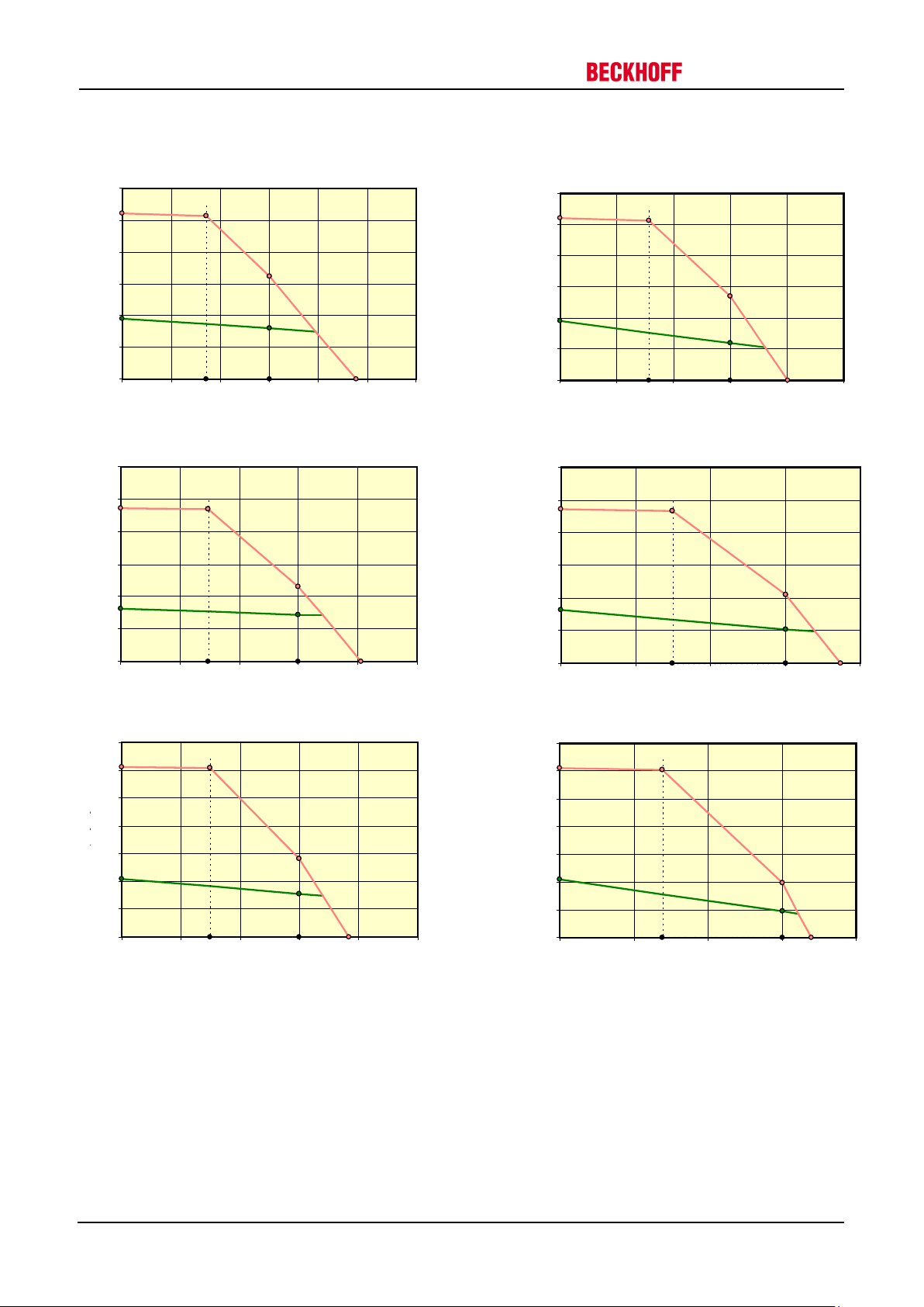
10 Technical data
1,9
1,2
2,7
5,2
8020
3140
0,00
1,0
2,0
3,0
4,0
5,0
6,0
0 2000 4000 6000 8000 10000
Torque [Nm]
AM3541 with 6000 rpm
Speed [rpm]
1,9
1,6
3,2
5,2
4770
1720
0,00
1,0
2,0
3,0
4,0
5,0
6,0
0 1000 2000 3000 4000 5000 6000
Torque [Nm]
AM3541 with 3000 rpm
Speed [rpm]
3,3
2,9
4,6
9,5
4060
1480
0,00
2,0
4,0
6,0
8,0
10,0
12,0
0 1000 2000 3000 4000 5000
Torque [Nm]
AM3542 with 3000 rpm
Speed [rpm]
3,3
2,1
4,2
9,5
7480
2980
0,00
2,0
4,0
6,0
8,0
10,0
12,0
0 2000 4000 6000 8000
Torque [Nm]
AM3542 with 6000 rpm
Speed [rpm]
4,2
3,1
5,6
12,3
3830
1490
0,00
2,0
4,0
6,0
8,0
10,0
12,0
14,0
0 1000 2000 3000 4000 5000
Torque [Nm]
AM3543 with 3000 rpm
Speed [rpm]
4,2
1,9
3,9
12,3
6790
2780
0,00
2,0
4,0
6,0
8,0
10,0
12,0
14,0
0 2000 4000 6000 8000
AM3543 with 6000 rpm
Speed [rpm]
Torque [Nm]
10.10.2 Characteristic torque / speed curves
Drive Technology
58 Version: 1.5 AM3000 / AM3500
Page 59

Data
Symbol [Unit]
AM3551
AM3552
AM3553
3000
6000
3000
3000
Electrical data
Standstill torque *
M0 [Nm]
4.1
6.3
8.6
Standstill current
I
orms
[A]
3.4
6.1
4.8
6.4
Max. rated mains voltage
UN [VAC]
480
Rated speed **
Nn [min-1]
3000
6000
3000
3000
Rated torque
Mn [Nm]
3.2
1.7
4.6
6.1
Rated current
In [A]
2.8
2.9
3.6
4.8
Peak current
I
0max
[A]
13.6
24
21
31
Peak torque
M
0max
[Nm]
11.1
11.1
18.5
27
Torque constant
K
Trms
[Nm/A]
1.19
0.66
1.32
1.34
Voltage constant
K
Erms
[mVmin]
72
40
80
81
Winding resistance
Ph-PH
R25 [Ω]
4
1.23
2.7
1.81
Winding inductance
Ph-PH
L [mH]
34
10.4
25.5
18.6
Mechanical data
AM3551
AM3552
AM3553
Rotor moment of inertia
J [kgcm2}
15
19
20
Pole number
10
Thermal time constant
tTH [min]
29
31
33
Weight, standard
G [kg]
5.8
7.0
8.9
Permitted radial load
at shaft end
FR [N]
594
648
682
Permitted axial load
at shaft end
FA [N]
113
123
130
Data
Symbol [Unit]
Value
Holding torque at 100 °C
MBR [Nm]
9
Supply Voltage
UBR[VDC]
24
Electrical power
PBR [W]
18
Current
Ion [A]
0.75
Release delay time
t
BRH
[ms]
40
Application delay time
t
BRL
[ms]
7
Moment of inertia
JBR [kgcm2]
0.6
Weight of the brake
GBR [kg]
0.82
Typical backlash
°mech
0
Drive Technology 10 Technical data
10.11 AM355x
*) reference flange aluminium 270 mm x 270 mm x 10 mm
Options such as sealing ring, holding brake, EnDAT or BiSS lead to a reduction of the rated data.
**) at 400 V supply voltage
Data for optional brake
Tolerances for all data ±10%
AM3000 / AM3500 Version: 1.5 59
Page 60

10 Technical data
Optional: Feather key
Motor type
Resolver
BiSS
Y
Z (brake)
Y
10.11.1 Dimensional drawing
AM3551 172 223 202 253
AM3552 202 262 232 292
AM3553 232 292 262 322
Drive Technology
60 Version: 1.5 AM3000 / AM3500
Page 61

4,1
1,7
4,2
11,1
8220
2290
0,00
2,0
4,0
6,0
8,0
10,0
12,0
14,0
0 2000 4000 6000 8000 10000
Torque [Nm]
AM3551 with 6000 rpm
Speed [rpm]
4,1
3,2
5,0
11,1
4570
1210
0,00
2,0
4,0
6,0
8,0
10,0
12,0
14,0
0 1000 2000 3000 4000 5000
Torque [Nm]
AM3551 with 3000 rpm
Speed [rpm]
6,3
4,6
6,7
18,5
4120
1070
0,00
5,0
10,0
15,0
20,0
25,0
0 1000 2000 3000 4000 5000
Torque [Nm]
Torque [Nm]
AM3552 with 3000 rpm
Speed [rpm]
Currently not
available
AM3552 with 6000 rpm
8,6
6,1
9,1
27,3
4070
990
0,00
5,0
10,0
15,0
20,0
25,0
30,0
35,0
0 1000 2000 3000 4000 5000
Torque [Nm]
Torque [Nm]
AM3553 with 3000 rpm
Speed [rpm]
AM3553 with 3000 rpm
Currently not
available
Drive Technology 10 Technical data
10.11.2 Characteristic torque / speed curves
AM3000 / AM3500 Version: 1.5 61
Page 62

10 Technical data
Data
Symbol [Unit]
AM3562
AM3563
3000
3000
Electrical data
Standstill torque *
M0 [Nm]
11.6
14.9
Standstill current
I
orms
[A]
10.3
12.5
Max. rated mains voltage
UN [VAC]
480 Rated speed **
Nn [min-1]
3000
3000
Rated torque
Mn [Nm]
8.4
10.9
Rated current
In [A]
7.9
9.6
Peak current
I
0max
[A]
49
49
Peak torque
M
0max
[Nm]
32
41
Torque constant
K
Trms
[Nm/A]
1.12
1.19
Voltage constant
K
Erms
[mVmin]
68
72
Winding resistance
Ph-PH
R25 [Ω]
0.71
0.48
Winding inductance
Ph-PH
L [mH]
11.4
8.5
Mechanical data
3562
3563
Rotor moment of inertia
J [kgcm2}
40
60
Pole number 10
Thermal time constant
tTH [min]
50
55
Weight, standard
G [kg]
10.7
13.6
Permitted radial load
at shaft end
FR [N]
672
713
Permitted axial load
at shaft end
FA [N]
128
135
Data
Symbol [Unit]
Value
Holding torque at 100 °C
MBR [Nm]
16
Supply Voltage
UBR[VDC]
24
Electrical power
PBR [W]
24
Current
Ion [A]
1
Release delay time
t
BRH
[ms]
50
Application delay time
t
BRL
[ms]
10
Moment of inertia
JBR [kgcm2]
2
Weight of the brake
GBR [kg]
1.1
Typical backlash
°mech
0
Drive Technology
10.12 AM356x
*) reference flange aluminium 345 mm x 345 mm x 10 mm
Options such as sealing ring, holding brake, EnDAT or BiSS lead to a reduction of the rated data.
**) at 400 V supply voltage
Data for optional brake
Tolerances for all data ±10%
62 Version: 1.5 AM3000 / AM3500
Page 63

Optional: Feather key
Motor
type
Resolver
BiSS
Y
Z (brake)
Y
Drive Technology 10 Technical data
10.12.1 Dimensional drawing
AM3562 223 262 233 289
AM3563 251 304 261 317
AM3000 / AM3500 Version: 1.5 63
Page 64

10 Technical data
14,9
10,9
20,4
40,5
4580
1380
0,00
5,0
10,0
15,0
20,0
25,0
30,0
35,0
40,0
45,0
0 1000 2000 3000 4000 5000
Torque [Nm]
AM3563 with 3000 rpm
Speed [rpm]
Currently not
available
11,6
8,4
15,2
31,5
4840
1060
0,00
5,0
10,0
15,0
20,0
25,0
30,0
35,0
0 1000 2000 3000
4000 5000 6000
Speed [rpm]
Torque [Nm]
Currently not
available
10.12.2 Characteristic torque / speed curves
Drive Technology
64 Version: 1.5 AM3000 / AM3500
Page 65

Drive Technology 11 Appendix
11 Appendix
11.1 Support and Service
Beckhoff and their partners around the world offer comprehensive support and service, making available fast
and competent assistance with all questions related to Beckhoff products and system solutions.
11.1.1 Beckhoff Support
Beckhoff offers comprehensive technical support that deals not only with the application of individual Beckhoff
products, but offers extensive additional services:
• support
• design, programming and commissioning of complex automation systems
• extensive training program for Beckhoff system components
Hotline : +49(0)5246/963-157
Fax : +49(0)5246/963-9157
e-mail : support@beckhoff.com
11.1.2 Beckhoff Service
The Beckhoff Service Center supports you in all matters of after-sales service:
• local service
• repair service
• spare parts service
Hotline : +49(0)5246/963-460
Fax : +49(0)5246/963-479
e-mail: : service@beckhoff.com
11.2 Beckhoff headquarters
Beckhoff Automation GmbH & Co. KG
Hülshorstweg 20
33415 Verl
Germany
Phone: +49(0)5246/963-0
Fax: +49(0)5246/963-198
e-mail: info@beckhoff.com
The addresses of the worldwide Beckhoff branch offices and representatives can be found on our website at
www.beckhoff.com You will also find further documentation for Beckhoff components there.
AM3000 / AM3500 Version: 1.5 65
 Loading...