

Page 1
Operation Manual
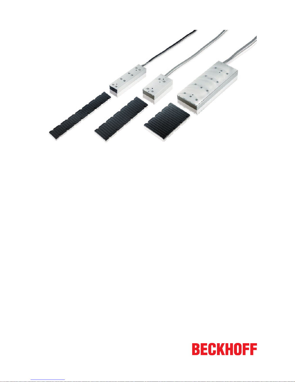
Linear servomotor AL2xxx
Air and water-cooled options
6.2
2018-09-21
Version:
Date:
Page 2

Page 3

Table of contents
Linear servomotor AL2xxx 3
Version: 6.2
Table of contents
1 Foreword ....................................................................................................................................................5
1.1 Notes on the documentation..............................................................................................................5
1.2 Documentation issue status ..............................................................................................................6
1.3 Intended use......................................................................................................................................7
2 Guidelines and Standards ........................................................................................................................8
2.1 EC declaration of conformity .............................................................................................................8
3 For your safety...........................................................................................................................................9
3.1 Staff qualification ...............................................................................................................................9
3.2 Description of symbols ....................................................................................................................10
3.3 Notes on the AL2xxx linear motors..................................................................................................11
4 Handling ...................................................................................................................................................14
4.1 Transport .........................................................................................................................................14
4.2 Storage ............................................................................................................................................14
4.3 Maintenance / Cleaning...................................................................................................................15
4.4 Disposal...........................................................................................................................................15
5 Product identification..............................................................................................................................16
5.1 AL2xxx scope of delivery.................................................................................................................16
5.2 AL2xxx name plate ..........................................................................................................................16
5.3 AL2xxx type key ..............................................................................................................................16
6 Technical description..............................................................................................................................17
6.1 Design of the motors .......................................................................................................................17
6.2 General technical data.....................................................................................................................17
6.2.1 Power derating................................................................................................................. 17
6.3 Standard features ............................................................................................................................18
6.3.1 Coil unit, primary part (N/S) ............................................................................................. 18
6.3.2 Magnetic plate, secondary part........................................................................................ 18
6.3.3 Magnetic Encoder System (MES) (optional).................................................................... 19
6.4 Additional equipment .......................................................................................................................19
6.4.1 Servo drive and feedback system.................................................................................... 20
7 Mechanical installation ...........................................................................................................................21
7.1 Important notes................................................................................................................................21
7.2 Order of assembly of the work unit..................................................................................................22
7.3 Assembling the magnetic plates......................................................................................................23
7.3.1 Inserting the locating pins ................................................................................................ 23
7.3.2 Attachment of the magnetic plates .................................................................................. 24
7.3.3 Coil unit and magnetic plate ............................................................................................ 24
7.4 Coupling of linear servomotors........................................................................................................25
7.4.1 Temperature sensor ........................................................................................................ 25
7.4.2 Layout of the motors ........................................................................................................ 25
7.4.3 Calculation of the offset ................................................................................................... 26
7.4.4 Layout of the wiring.......................................................................................................... 26
7.4.5 Positions of the phase lines ............................................................................................. 27
7.4.6 Minimum distance between the motors ........................................................................... 29
Page 4

Table of contents
Linear servomotor AL2xxx4
Version: 6.2
7.5 Dismantling sequence .....................................................................................................................30
8 Electrical installation...............................................................................................................................31
8.1 Important notes................................................................................................................................31
8.2 Connection of motors ......................................................................................................................32
8.2.1 Single conductors ............................................................................................................ 32
8.2.2 M23 connector for power supply and D-Sub connector for temperatur contact .............. 33
8.3 Connection with pre-assembled cables and connector box AL225x ...............................................34
8.3.1 AX5000 connection diagram with MES and Sin/Cos encoder without zero pulse........... 35
8.3.2 AX5000 connection diagram for AL2xxx and absolute value encoder ............................ 36
8.3.3 AX5000 connection diagram for AL2xxx and Sin/Cos encoder with zero pulse ............. 37
8.3.4 AX5000 connection diagram for AL2xxx and TTL encoder with zero pulse ................... 38
8.4 Temperature sensor ........................................................................................................................39
8.4.1 PTC specification............................................................................................................. 39
8.4.2 KTY Specification ............................................................................................................ 39
8.5 Polarity test......................................................................................................................................40
9 Installation of the water cooling.............................................................................................................41
9.1 General............................................................................................................................................41
9.2 Requirements ..................................................................................................................................41
9.3 Installation of the water cooling connections ...................................................................................42
9.3.1 AL2xxx ............................................................................................................................. 42
9.3.2 AL28xx-1 water-cooled .................................................................................................... 42
9.4 Connecting the hoses......................................................................................................................43
10 Commissioning........................................................................................................................................44
10.1 Important notes................................................................................................................................44
10.2 General commissioning ...................................................................................................................44
10.2.1 Parameterisation.............................................................................................................. 44
10.2.2 Commissioning ................................................................................................................ 45
10.2.3 Optimising the control settings......................................................................................... 45
10.3 Troubleshooting...............................................................................................................................46
11 Technical data..........................................................................................................................................47
11.1 Term definitions ...............................................................................................................................47
11.2 AL20xx.............................................................................................................................................48
11.2.1 Dimensional drawing, AL20xx and AL21xx ..................................................................... 50
11.3 AL24xx.............................................................................................................................................51
11.3.1 Dimensional drawing, AL24xx and AL25xx ..................................................................... 52
11.4 AL28xx-0 air-cooled.........................................................................................................................53
11.4.1 Dimensional drawing, AL28xx-0 air-cooled and AL29xx ................................................. 54
11.5 AL28xx-1 water-cooled....................................................................................................................55
11.5.1 Dimensional drawing, AL28xx-1 water-cooled and AL29xx............................................. 56
11.6 Calculation of the brake resistor ......................................................................................................57
12 Support and Service................................................................................................................................58
Page 5
Foreword
Linear servomotor AL2xxx 5
Version: 6.2
1 Foreword
1.1 Notes on the documentation
This description is only intended for the use of trained specialists in control and automation engineering who
are familiar with the applicable national standards.
It is essential that the documentation and the following notes and explanations are followed when installing
and commissioning the components.
It is the duty of the technical personnel to use the documentation published at the respective time of each
installation and commissioning.
The responsible staff must ensure that the application or use of the products described satisfy all the
requirements for safety, including all the relevant laws, regulations, guidelines and standards.
Disclaimer
The documentation has been prepared with care. The products described are, however, constantly under
development.
We reserve the right to revise and change the documentation at any time and without prior announcement.
No claims for the modification of products that have already been supplied may be made on the basis of the
data, diagrams and descriptions in this documentation.
Trademarks
Beckhoff®, TwinCAT®, EtherCAT®, Safety over EtherCAT®, TwinSAFE®, XFC® and XTS® are registered
trademarks of and licensed by Beckhoff Automation GmbH.
Other designations used in this publication may be trademarks whose use by third parties for their own
purposes could violate the rights of the owners.
Patent Pending
The EtherCAT Technology is covered, including but not limited to the following patent applications and
patents:
EP1590927, EP1789857, DE102004044764, DE102007017835
with corresponding applications or registrations in various other countries.
The TwinCAT Technology is covered, including but not limited to the following patent applications and
patents:
EP0851348, US6167425 with corresponding applications or registrations in various other countries.
EtherCAT® is registered trademark and patented technology, licensed by Beckhoff Automation GmbH,
Germany
Copyright
© Beckhoff Automation GmbH & Co. KG, Germany.
The reproduction, distribution and utilization of this document as well as the communication of its contents to
others without express authorization are prohibited.
Offenders will be held liable for the payment of damages. All rights reserved in the event of the grant of a
patent, utility model or design.
Page 6

Foreword
Linear servomotor AL2xxx6
Version: 6.2
1.2 Documentation issue status
Origin of the document
This documentation was originally written in German. All other languages are derived from the German
original.
Product features
Only the product features specified in the current user documentation are valid. Further information given on
the product pages of the Beckhoff homepage, in emails or in other publications is not authoritative.
Issue Comment
6.2 Chapter revision:
Technical data AL20xx 11.2; Technical data AL24xx 11.3; Technical data AL28xx-0 aircooled 11.4; AL28xx-1 water-cooled 11.5
Removed Chapter:
M23 connector for power supply and temperature contact 8.2.3
6.1 Chapter revision:
EC declaration of conformity 2.1; AL2xxx name plate 5.2; AL2xxx type key 5.3;
Connection of motors with 8.2 Connection diagrams for AL2xxx 8.3.1 – 8.3.4; Technical
data AL2418 11.3
New chapter:
M23 connector for power supply and temperature contact 8.2.3
6.0 Complete revision
5.8 Chapter revision:
Technical data 10.2 – 10.5
5.7 Chapter revision:
Disposal 4.5
5.6 Chapter revision:
EC Declaration of Conformity 2.1; Technical data 11
5.5 Chapter revision:
1.0 Foreword; 3.0 Safety
5.4 Chapter revision:
Documented motors; 6.3.3; 7.4.2; 8.2.2; 8.4.2; 11.2; 11.3; 11.4; 11.5; 11.5.1
5.3 Chapter revision:
11.2; 11.3; 11.4; 11.5
5.2 Chapter revision
8.2 became 8.3; 3.2
New chapter
8.2; 8.2.1; 8.2.2
5.1 Chapter revision
Documented motors - chapter; 3.2; 11; 11.1: 11.2; 11.3; 11.4; 11.5
5.0 Chapter revision
Documented motors - chapter; 1.2; 2.1; 3.2; 4.2; 4.3; 4.5; 6.3.2; 6.3.3; 7; 7.3; 7.3.2; 7.4.6;
7.5; 8.2.1; 8.2.2; 8.2.3; 8.2.4; 8.3.2; 9.3.1;10; 10.2.3; 10.3; 11; 11.1; 11.2; 11.2.1; 11.4;
11.5.1; 11.6
Complete revision
Page 7
Foreword
Linear servomotor AL2xxx 7
Version: 6.2
1.3 Intended use
Linear servo motors from the AL2xxx series are intended exclusively for driving handling devices, textile
machines, machine tools, packaging machines and similar machines that place high demands on the
dynamics.
The linear motors are installed exclusively as components in electrical systems or machines and may only be
put into operation as integrated components of the plant or machine.
The thermal protection contact incorporated in the motor windings must be analyzed and monitored.
WARNING
Caution - Risk of injury!
Basically, electronic devices are not fail-safe. The machine manufacturer is responsible for ensuring that
the connected motors and the machine are brought into a safe state in the event of a fault in the drive system.
The linear motors may be operated only under the environmental and operating conditions [
}17] defined
in this documentation.
Improper use
Beckhoff linear motors from the AL2xxx series are not suitable for use in the following areas:
• in ATEX zones without a suitable housing
• in areas with aggressive environments (e.g. aggressive gases or chemicals)
The relevant standards and directives for EMC interference emissions must be complied with in residential
areas.
Page 8
Guidelines and Standards
Linear servomotor AL2xxx8
Version: 6.2
2 Guidelines and Standards
CAUTION
Personal injuries!
Linear servomotors from the AL2xxx series are not products within the meaning of the EU machinery directive. Operation of the linear servomotors in machines or systems is only permitted once the machine or system manufacturers has provided evidence of CE conformity of the complete machine or system.
2.1 EC declaration of conformity
Provision of EU Declaration of Conformity:
Beckhoff Automation GmbH & Co. KG will be glad to provide you with EU declarations of conformity
and manufacturer's declarations for all products upon request to info@beckhoff.com.
Page 9

For your safety
Linear servomotor AL2xxx 9
Version: 6.2
3 For your safety
Read the section on safety and heed the notices to protect yourself against personal injury and material
damages.
Limitation of liability
The entire components of the Beckhoff AL2xxx linear motors are delivered in certain hardware and software
configurations according to the application requirements. Unauthorized modifications to the hardware and/or
software configurations other than those described in the documentation are not permitted, and nullify the
liability of Beckhoff Automation GmbH & Co. KG.
In addition, the following actions are excluded from the liability of Beckhoff Automation GmbH & Co.
KG:
• Failure to comply with this documentation
• Improper use [
}7]
• Untrained personnel
• Use of unauthorized spare parts
3.1 Staff qualification
All depicted work to be done on the Beckhoff software and hardware, and in particular on the AL2xxx linear
motors, may be carried out only by technical personnel with knowledge of control and automation
technology.
The technical personnel must have knowledge of drive technology and electrical systems and must also
know how to work safely on electrical equipment and machines.
This also includes:
• production planning and
• securing of the working environment (e.g. securing the control cabinet against being switched on
again).
The technical personnel must be familiar with the current and necessary standards and directives for the
automation and drive environment.
Page 10
For your safety
Linear servomotor AL2xxx10
Version: 6.2
3.2 Description of symbols
In this documentation the following symbols are used with an accompanying safety instruction or note. The
safety instructions must be read carefully and followed without fail!
Symbols that warn of personal injury:
DANGER
Serious risk of injury!
This is an extremely dangerous situation. Disregarding the safety notice will lead to serious permanent injuries or even death.
WARNING
Risk of injury!
This is a dangerous situation. Disregarding the safety notice may lead to serious injuries.
CAUTION
Personal injuries!
This is a dangerous situation. Disregarding the safety notice may lead to minor injuries.
Symbols that warn of damage to property or equipment:
NOTE
Warning of damage to property or the environment!
This notice indicates disturbances in the operational procedure that could damage the product or the environment.
Symbols indicating further information or tips:
Tip or pointer!
This notice provides important information that will be of assistance in dealing with the product or
software. There is no immediate danger to product, people or environment.
UL note!
This symbol indicates important information regarding UL certification.
Page 11
For your safety
Linear servomotor AL2xxx 11
Version: 6.2
3.3 Notes on the AL2xxx linear motors
The notes are intended to avert danger and to provide instructions on the handling of the AL2xxx linear
motors. They must be followed during installation, commissioning, production, troubleshooting, maintenance
and trial or test assemblies.
The linear motors from the AL2xxx series cannot run as stand-alone devices. They must always be installed
in a machine or system. After installation the additional documentation and safety instructions provided by
the machine manufacturer must be read and followed.
DANGER
Danger to life due to high voltage on the DC link capacitors of the servo drive AX8000!
The DC link capacitors RB+ and RB- and the test contacts DC+ and DC- on the
supply, axis and option modules can carry life-threatening voltages of
≥ 875 VDC.
Take the following measures to avert danger:
• After disconnecting the servo drive from the mains supply, wait until the voltage has fallen below 50
VDC. Only then is it safe to work.
• Measure the voltage on the test contacts properly.
• Secure the work area properly and wear the PPE.
DANGER
Deadly danger due to high voltage on the DC link capacitors of the AX5000 servo drive!
Due to the DC link capacitors, the DC link terminal points "ZK+ and ZK- (DC+ and DC-)" and "RB+ and
RB-" may be subject to dangerous voltages of up to 875VDC, even after the servo drive was disconnected
from the mains supply.
Take the following measures to avert danger:
• Wait:
- 5 minutes in the case of the AX5101 - AX5125 and AX520x
- 15 minutes in the case of the AX5140/AX5160/AX5172
- 30 minutes in the case of the AX5190/AX5191
- 45 minutes in the case of the AX5192/AX5193
after disconnecting the servo drive from the mains supply. It is only safe to work after the voltage has
dropped below 50 V.
• Measure the voltage on the test contacts properly.
• Secure the working area properly and wear the PPE.
CAUTION
Proper connection of the protective earth conductor!
Protective earth systems must be connected when installing electrical systems and components.
Please observe the following notes when installing the protective earth conductor:
• Make sure that the protective earth conductor has been firmly connected.
• Disconnect the servo drive and all electrical components from the mains supply. Secure the control
cabinet and the devices against being switched on again.
• Wear PPE.
Page 12

For your safety
Linear servomotor AL2xxx12
Version: 6.2
WARNING
Risk of severe burns due to hot surfaces on the linear motor!
During the operation of the system the surface temperature of the linear motors can reach ≥ 50°C. There is
an acute risk of sustaining burns to parts of the body and limbs.
Take the following measures to avert danger:
• Do not touch any components (housing, etc.) shortly after or during operation.
• Wait until all components have cooled sufficiently. At least 15 minutes.
• Check the surface temperature with a thermometer.
• DO NOT wear work gloves with a rubber coating. These can fuse with the skin on account of the high
temperature and cause serious injuries.
Notes on the operation of the AL2xxx linear motors:
• Read this manual carefully and completely before using the linear motor. Notify the responsible
sales office immediately if any passages are not understandable. Do not work on the linear motor.
• Adhere without fail to the climatic conditions for the installation. Further information can be
found in the Technical data
[}47] and Mechanical installation [}21] sections.
NOTE
High temperatures can damage the magnets!
Do not expose the magnets to temperatures ≥ 70°C. This can lead to demagnetization.
Deadly danger due to the magnetic fields of the linear motor!
The AL2xxx linear motors are equipped with permanent magnets in the magnetic plate. Strong
magnetic fields are present here. In the power-off state, the magnetic field strength of the motors results exclusively from the magnetic fields of the secondary part.
There is a particular danger for:
people fitted with cardiac pacemakers
(The cardiac pacemaker can be switched to test mode and thus cause a cardiac arrest!)
People with implanted defibrillators
(The defibrillators can be rendered inoperative by the magnetic field!)
NOTE
Loss of data due to magnetic fields!
-- Magnetic data storage devices
-- Chip cards with magnetic strips and
-- Electronic devices can be demagnetized by magnetic fields.
There is a risk of the loss of data.
The objects listed above and loose-lying ferromagnetic objects may not be brought any closer than 1 m to
the magnetic plates.
The requirements in BGV B 11 applying to magnetic fields and the national regulations applicable in other
countries must be observed.
Page 13
For your safety
Linear servomotor AL2xxx 13
Version: 6.2
CAUTION
Risk of crushing and injury due to magnets!
The AL2xxx linear motors are equipped with permanent magnets in the magnetic plate. (Crushing) injuries
may be sustained during commissioning due to magnetic attractive forces.
Take the following measures to avert danger:
• Move the magnetic components slowly towards one another.
• Wear PPE for all work on the magnets!
• Avoid shocks or jerky contact between magnets. This could lead to splintering and eye injuries. Wear
safety goggles.
• Make sure that there are no ferromagnetic tools or materials nearby in your working environment.
These could be attracted by the magnetic field and cause injuries to body parts.
Notes on the transport of magnetic material!
Please observe the IATA regulation 953 when transporting magnetic material. The AL2xxx magnetic plates fall below the limit values and may be dispatched.
Page 14
Handling
Linear servomotor AL2xxx14
Version: 6.2
4 Handling
4.1 Transport
NOTE
Short-circuit due to moisture in the AL2xxx linear motors!
Condensation may form when transporting in cold weather or in the case of extreme temperature differences:
• Make sure that no moisture condenses inside the linear motor packaging (bedewing). Equalize the
room temperature slowly. Only switch the linear motor on when it is completely dry.
Despite the sturdy construction, the components are sensitive to strong vibrations and impacts.
During transport, protect the product against:
• high mechanical stress
• large temperature fluctuations (max. 20 K/hour)
• excessively high humidity (max. relative humidity 95%, non-condensing)
For the dispatch, use proper packaging that meets the requirements specified in this chapter for the transport
of the linear motors. This could also be the manufacturer's original packaging.
Since linear motors contain electrostatically sensitive components that can be damaged by improper
treatment:
• Avoid electrostatic charging before you touch the device or components directly.
• Avoid contact with highly insulating materials (synthetic fibers, plastic film etc.).
• Place the servo drive on a conductive surface.
• If the packaging is damaged, inspect the linear motor and any accessories for visible damage. Inform
the transport company and, if necessary, the manufacturer.
Packaging
Motor type Max. stacking height
AL2xxx 8
4.2 Storage
• The linear motor and accessories may not be stored outdoors. The storage space must be adequately
ventilated and dry.
• The devices may only be stored in the manufacturer's original packaging.
• Climate category: 2K3 according to EN 60721
• Storage temperature: -25°C to +55°C, max. fluctuation 20 K/hour
• Air humidity: relative humidity max. 95%, non-condensing
• Storage time: without limitation
Page 15

Handling
Linear servomotor AL2xxx 15
Version: 6.2
4.3 Maintenance / Cleaning
• Maintenance and cleaning only by qualified personnel.
• Opening the motor invalidates the warranty.
• Clean the housing with isopropanol or similar.
NOTE
Destruction of the linear servomotor
Never immerse or spray the linear servomotor.
Proper functioning of the bearings and buffers, and guidance of the movable lines, must all be tested.
4.4 Disposal
In accordance with the WEEE 2012/19/EU Directives we take old devices and accessories back for
professional disposal, provided the transport costs are taken over by the sender.
Send the devices with the note “For disposal” to:
Beckhoff Automation GmbH & Co. KG
Huelshorstweg 20
D-33415 Verl
Page 16
Product identification
Linear servomotor AL2xxx16
Version: 6.2
5 Product identification
5.1 AL2xxx scope of delivery
Please check that the delivery includes the following items:
• Motor from the AL2xxx series
• Type plate
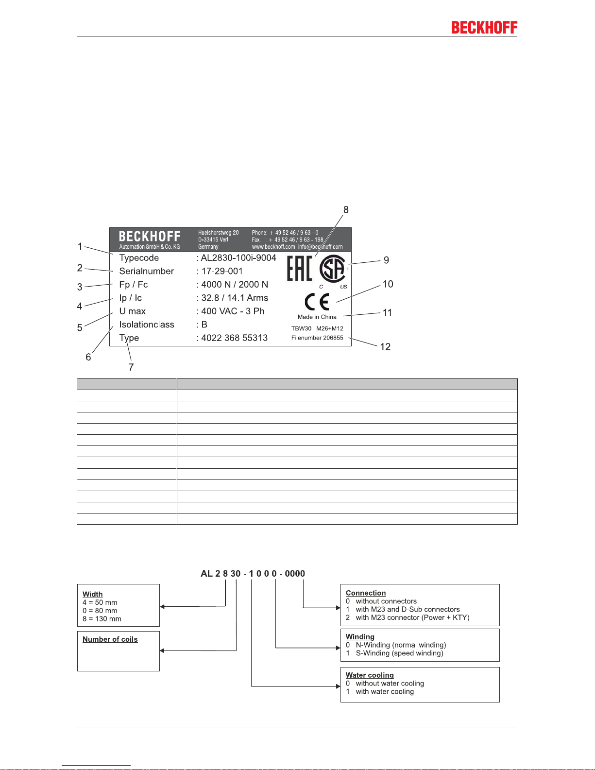
5.2 AL2xxx name plate
Pos. - No. Description
1 Type of the linear motor
2 Serial number
3 Peak force
4 Peak current
5 Max. Voltage
6 Insulation class
7 Type code
8 EAC mark of conformity
9 CSA mark of conformity
10 CE mark of conformity
11 Country of manufacture
12 File number
5.3 AL2xxx type key
Page 17
Technical description
Linear servomotor AL2xxx 17
Version: 6.2
6 Technical description
6.1 Design of the motors
The linear servomotors from the AL2xxx series are brushless three-phase motors for high-quality servo
applications. In conjunction with our digital servo drives they are particularly suitable for positioning tasks in
industrial robots, machine tools, transfer lines, handling equipment, textile machines, packaging machines,
etc. with high requirements for dynamics and stability. The motors from the AL2xxx series are intended to be
operated exclusively by a digital servo drive with speed and torque control.
The linear servomotors are equipped with permanent magnets in the magnetic plate. This advanced
neodymium magnetic material makes a significant contribution to the motors' exceptional dynamic
properties. A three-phase coil unit supplied by the servo drive is housed in the coil unit. The motor has no
brushes; the commutation being implemented electronically in the servo drive.
Furthermore, a feedback system is necessary for operation. The suitable feedback system must be selected
on the basis of the application requirements. Dynamics, speed, contamination levels, resolution and the
servo drive must be considered (see also the section entitled Magnetic Encoder System (MES) (optional)
[}19]).
6.2 General technical data
Ambient and operating conditions
Climate category 3K3 according to EN 60721
Ambient temperature
(at rated values)
+5 - +40 °C for installation altitudes up to 1000 m amsl
→ see section entitled Power derating
[}17]
Permissible humidity
(at rated values)
95% relative humidity, non-condensing
Installation altitude
(currents and torques)
At installation altitudes of 1000 m or higher above sea level and an ambient
temperature of 40 °C
→ see section entitled Power derating
[}17]
Technical data
→ See section entitled Technical data [}47]
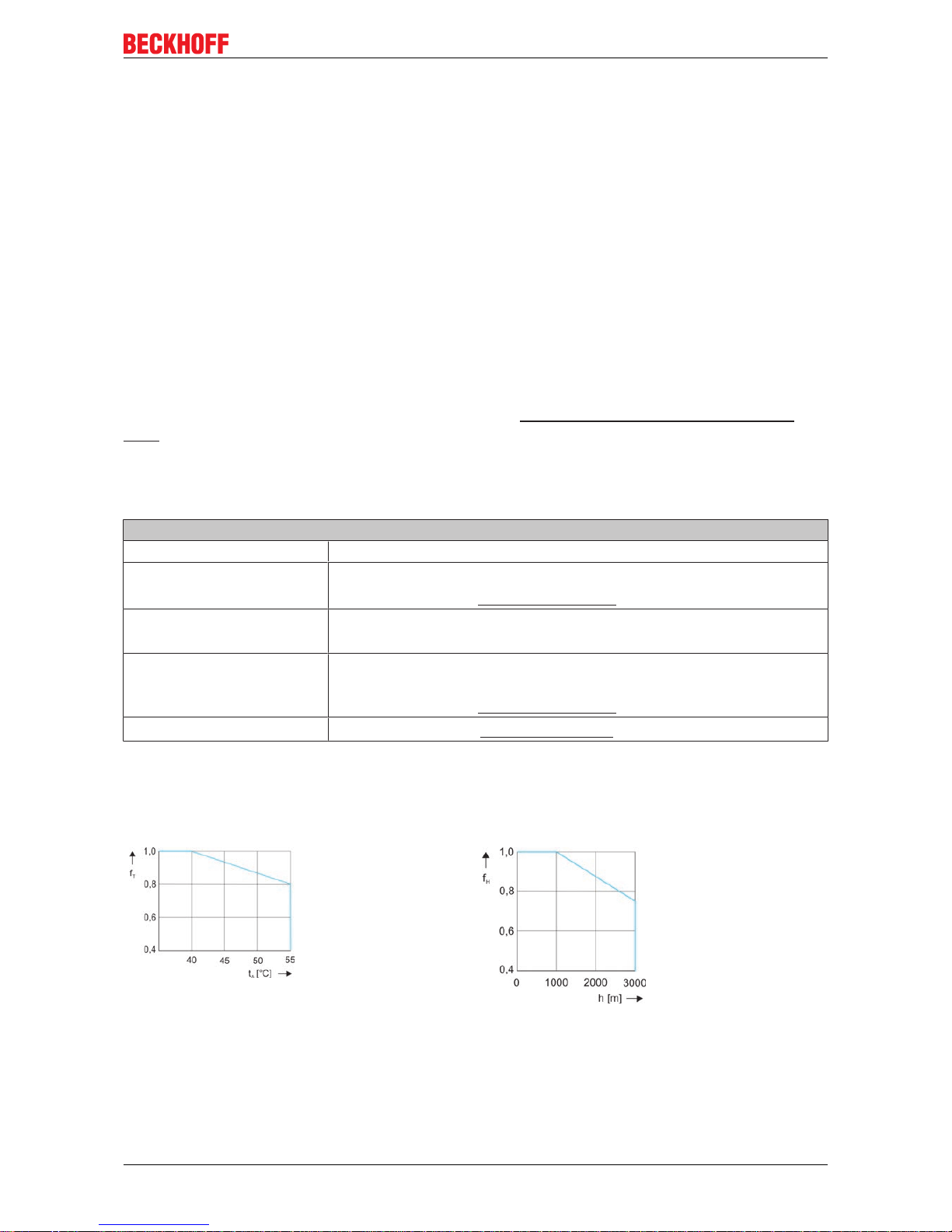
6.2.1 Power derating
Ambient temperature Installation altitude
fT = Temperature
utilization factor
tA = Ambient temperature
°C
fH = Altitude utilization
factor
h = Altitude in meters
Calculation of the power data when exceeding the
specified temperature limit > 40 °C:
F
CA_red
= FCA x f
T
Calculation of the power data when exceeding the
specified installation altitude ≥ 1000 m:
F
CA_red
= FCA x f
H
Calculation of the power data when exceeding the specified limits:
Ambient temperature > 40 °C and installation altitude ≥ 1000 m
F
CA_red
= FCA x fT x f
H
Page 18
Technical description
Linear servomotor AL2xxx18
Version: 6.2
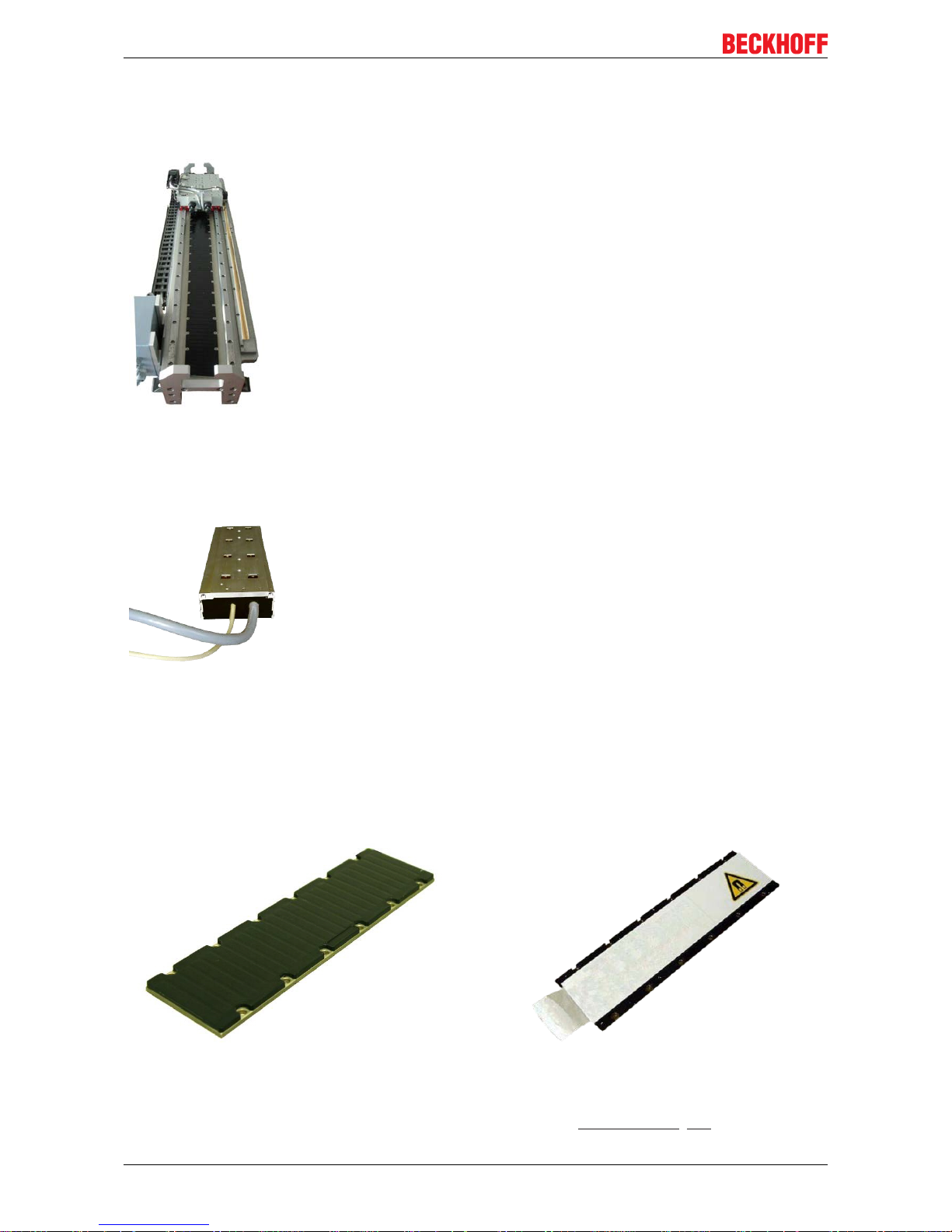
6.3 Standard features
Machine concept
The AL2xxx linear servomotor series from Beckhoff is not a self-contained
system. It includes various components such as a coil unit and magnetic plates
and must be integrated into a complete machine concept or a complete working
unit.
The size and shape of the carrier frame, the design of the carriage, the type of
rail and type of bearings, and the kind of buffer used depend on the application.
The carrier frame and the carriage must be designed such that an air gap is
created between the coil unit and the magnetic plate.
6.3.1 Coil unit, primary part (N/S)
Winding types
The N-type (normal winding) represents the preferred type. The Stype (speed winding) has a higher maximum speed and a higher
current consumption. The dimensions of the N-type and S-type do not
differ.
6.3.2 Magnetic plate, secondary part
Magnetic plates are available in various lengths and can be combined with one another as desired within a
series. Different series require magnetic plates with different widths.
Magnetic plate without transport plate Magnetic plate with transport plate
In the delivery condition the magnetic plates are covered by a transport plate. It reduces the magnetic field
and thus enables simple mounting and dismounting.
Specifications and dimensional drawings can be found in the chapter: Technical data [
}47]
Page 19

Technical description
Linear servomotor AL2xxx 19
Version: 6.2
6.3.3 Magnetic Encoder System (MES) (optional)
The Magnetic Encoder System (MES) AL2200-000y is a position measuring system. It has an accuracy of
0.1 mm and works directly on the magnetic plates. There are no further measuring scales. Fastening takes
place on the carriage.
Description of the position measuring system
The MES works absolute within the pole distance (24 mm) and semi-absolute over the entire track. The
distance to the coil part is not relevant. The commutation angle is determined once during commissioning.
The wake & shake at the start of the machine is thus dispensed with. Homing can be carried out if an
absolute synchronization is desired.
Documentation for the Magnetic Encoder System (MES)!
Further information on the Magnetic Encoder System (MES) can be found on the Beckhoff homepage under: MES Feedback Documentation
or in the Beckhoff Online Information System.
6.4 Additional equipment
You require further components for the proper installation of your linear servomotor.
These are not included in the scope of delivery.
Screws and locating pins
The screws and locating pins are needed to position and fasten the coil
unit to the carriage, and also the magnetic plates to the carrier frame.
Attribute AL20xx AL24xx AL28xx
Screws for magnetic plates
(stainless)
M5x10, DIN7984 M5x10, DIN7984 M5x16, EN ISO 4762
Screws for coil unit (steel);
Length depends on the
thickness of the carriage
M5, EN ISO 4762 M4, EN ISO 4762 M5, EN ISO 4762
Locating pins (stainless) 5h8
Page 20

Technical description
Linear servomotor AL2xxx20
Version: 6.2
6.4.1 Servo drive and feedback system
The following components are required for the construction of a complete linear axis and its operation:
• Servo drive, e.g.: AX5xxx from Beckhoff Automation GmbH.
• Graduated rule and linear displacement transducer or the MES feedback system without graduated
rule
• Cables and plugs
• Guides
• Mechanical support / machine bed
Page 21

Mechanical installation
Linear servomotor AL2xxx 21
Version: 6.2
7 Mechanical installation
7.1 Important notes
Installation of the machine bed must be complete before installing the linear motor components. The rails
must be mounted on the machine bed and aligned. The carriage must be equipped with bearings, dampers
and the required lines so that the proper movement of the carriage over the track is ensured.
WARNING
Damage due to uncontrolled magnetic attractive forces
The sequence specified in this introduction for the installation must be followed. A different sequence can
give rise to dangerous situations, and can lead to damage resulting from uncontrolled magnetic attraction.
Damage due to faulty water cooling unit
If a water cooling unit is to be used, read please the section entitled Installation of the water cooling
[}41].
Deadly danger due to the magnetic fields of the linear motor!
The AL2xxx linear motors are equipped with permanent magnets in the magnetic plate. Strong
magnetic fields are present here. In the power-off state, the magnetic field strength of the motors results exclusively from the magnetic fields of the secondary part.
There is a particular danger for:
people fitted with cardiac pacemakers
(The cardiac pacemaker can be switched to test mode and thus cause a cardiac arrest!)
People with implanted defibrillators
(The defibrillators can be rendered inoperative by the magnetic field!)
NOTE
Loss of data due to magnetic fields!
-- Magnetic data storage devices
-- Chip cards with magnetic strips and
-- Electronic devices can be demagnetized by magnetic fields.
There is a risk of the loss of data.
The objects listed above and loose-lying ferromagnetic objects may not be brought any closer than 1 m to
the magnetic plates.
The requirements in BGV B 11 applying to magnetic fields and the national regulations applicable in other
countries must be observed.
CAUTION
Damage due to a magnetic field that is not neutralized
Use the magnetic plates only when they are covered by the protective plates that reduce the magnetic field.
CAUTION
Damage during dismantling due to the magnetic field
Make sure that the magnetic plates are fastened in your machine before removing the protective plates.
Put the protective plates back onto the magnetic plates before dismantling them.
Do not bring any soft-magnetic objects (iron) closer than 10 cm to the magnetic side of the magnetic plates.
Page 22

Mechanical installation
Linear servomotor AL2xxx22
Version: 6.2
7.2 Order of assembly of the work unit
Fastening the coil unit
Observe the following notes before beginning
assembly. Deviations from flatness of the surface on
which the coil unit will rest must be less than 0.1 mm.
The coil unit must be assembled parallel to the
magnetic plate. Parallelism must be closer than 0.20
mm. The sides of the coil unit, or the round holes in
the supporting surface, can be used for this purpose.
Locating pins can be inserted into the round holes.
Lateral positioning of the coil unit with respect to the
magnetic plates is not particularly critical. A tolerance
of up to ±0.5 mm is acceptable.
Item no. Explanation Item no. Explanation
1 Magnetic plate 5 Buffers
2 Bearing 6 Carriage
3 Cabling 7 Graduated rule
4 Coil unit 8 Rail
Please note the following comments and information:
Order of tightening the screws:
Fasten the screws in a crisscross pattern, so that the resulting forces are distributed evenly.
NOTE
The coil unit can be damaged by incorrect screwing!
Using screws that are too long for the coil unit can cause damage that is not immediately visible, and give
rise to dangerous situations.
Check:
• the screw length
• the screw height after the installation.
Screws for the coil unit AL20xx AL24xx AL28xx
Screw (steel) M5 M4 M5
Depth in the coil unit Min: 4mm
Max: 5mm
Min: 4 mm
Max: 5 mm
Min: 4.5 mm
Max: 6.5 mm
Tightening torque 3.0 – 5.0 Nm 2.0 – 3.0 Nm 3.0 – 5.0 Nm
Distance of the water cooling connections:
Note that the connections for the water cooling can extend up to 1 mm beyond the dimensions of
the coil part. Ensure that enough clearance is maintained, or else use a spacer plate at least 1 mm
thick. See also the section entitled Installation of the water cooling
[}41] (additional installation in-
structions / water cooling).
Page 23

Mechanical installation
Linear servomotor AL2xxx 23
Version: 6.2
7.3 Assembling the magnetic plates
Fastening the magnetic plates
The textured side of the plate is the magnetic side.
The magnetic plates exert a strong attractive force on
all ferromagnetic metals such as iron. These forces
cannot be controlled with the hands. They can cause
serious injuries.
7.3.1 Inserting the locating pins
CAUTION
The linear motor can be damaged by unwanted movements of the carriage!
If the carriage is already mounted, move it to one end of the track and secure it to prevent unwanted movements.
Dimensioning the locating pins:
The locating pins may not extend any more than 3.3 mm above the machine bed.
Inserting the locating pins in the magnetic plate Assembling the magnetic plate
Proceed as follows:
• Manufacture the positioning holes (2) in the
machine bed (1) analogous to the 5 mm
positioning holes (4) in the magnetic plate (3).
• Insert the locating pins (2) into the positioning
holes (2) in the machine bed (1).
• Manufacture the tapped holes (5) analogous to the
mounting holes (6) in the magnetic plate (3).
Proceed as follows:
• Cleanse the locating surface of dust and particles.
• Mount the magnetic plate on the locating surface
of the track.
Page 24

Mechanical installation
Linear servomotor AL2xxx24
Version: 6.2
7.3.2 Attachment of the magnetic plates
Fastening the magnetic plate to the machine bed Removing the protective plates
Proceed as follows:
• Align all the magnetic plates in the same direction.
Example:
All magnetic plates must be attached in such a
way that the positioning holes point to the right
upper corner.
• Fasten the magnetic plate to the machine bed. The
minimum screw-in depth should be 6.5 mm. The
tightening torque is 2.5 to 3.5 Nm.
• The other magnetic plates can now be assembled
in a same way.
Proceed as follows:
• Remove all protective plates.
• Check that the carriage can move smoothly and
without hindrance over the magnetic plates.
• The alignment of the magnetic plates should be
checked if there are significant variations in the
force when moving from one magnetic plate to the
next.
Alignment of the magnetic plates:
Adjacent plates must attract one another. If they repel one another, they are wrongly aligned.
7.3.3 Coil unit and magnetic plate
In the case of the motors from the AL2000 and AL2400 series, observe the offset of the coil unit to the
magnetic plate. The AL2800-0 series lines up flush with the magnetic plate on one side. The installation
position of the respective motor is to be taken from the relevant dimensional drawings.
By taking into consideration the mounting height, an air gap of ≤ 0.5 mm results between the coil unit and the
magnetic plate. With this air gap the motor reliably achieves its rated performance.
Page 25

Mechanical installation
Linear servomotor AL2xxx 25
Version: 6.2
7.4 Coupling of linear servomotors
Linear servomotors can be connected with one another in order to act together on a magnetic track. The
forces of the motors are added together. The motors are connected in parallel to the controller, which leads
to a higher total current. Motors of the same type can always be connected to one another. Motors of
different types but from the same series can be connected together if their power constants are equal.
7.4.1 Temperature sensor
Use the temperature sensor of the motor which has the poorest cooling and which will thus have the higher
temperature development.
7.4.2 Layout of the motors
The motor windings have a fixed distance to one another that depends on the series. In the case of the
AL2xxx series this is 16 mm. If linear servomotors are coupled with one another, there must be a multiple of
this winding distance between the windings of the connected motors as well.
Phase repetition = 3 x winding distance = 3 x 16 mm = 48 mm
Example 1 with AL2006 and AL2012 Example 2 with AL2006 and AL2012
In example 1 the connecting cables of the motors
point in different directions. This enables the
minimum distance between the linear
servomotors.
In example 2 the connecting cables point in the
same direction. In this layout the minimum
bending radius of the motor cable must be
observed.
PD
M1M2
= phase distance “Phase L1 / Motor 1” to
“Phase L1 / Motor 2”
x = Housing clearance
z = Distance of the locating pin holes
PD
M1M2
= phase distance “Phase L1 / Motor 1” to
“Phase L1 / Motor 2”
x = Housing clearance
z = Distance between the mounting holes
Page 26

Mechanical installation
Linear servomotor AL2xxx26
Version: 6.2
7.4.3 Calculation of the offset
The wiring must be done according to the layout of the coil units. The offset must be determined in order to
do this. The offset specifies the number of coils by which the rotary field is shifted in the second motor. The
wiring of the motors can be determined with the help of the offset and the table in the section entitled Layout
of the wiring [}26].
The offset is calculated using the following equation:
Offset = (PD
M1M2
/ 16) MOD 3
Calculation of the offset for example 1:
Offset = (304 / 16) MOD 3
= 19 MOD 3 = 1
Calculation of the offset for example 2:
Offset = (272 / 16) MOD 3
= 17 MOD 3 = 2
7.4.4 Layout of the wiring
Using the offset calculated in the previous section, the wiring of the coupled motors can be done on the basis
of the following table. For each case the table shows how the phases of motor 1 (L1, L2, L3) are connected
to the phases of motor 2 (L1’, L2’, L3’).
Cables of the motors
point in the same direction
Cables of the motors
point outwards
Cables of the motors
point inwards
Offset = 0 L1/L1‘ L2/L2‘ L3/L3‘ L1/L1‘ L2/L3‘ L3/L2‘ L1/L1‘ L2/L3‘ L3/L2‘
Offset = 1 L1/L3‘ L2/L1‘ L3/L2‘ L1/L2‘ L2/L1‘ L3/L3‘ L1/L3‘ L2/L2‘ L3/L1‘
Offset = 2 L1/L2‘ L2/L3‘ L3/L1‘ L1/L3‘ L2/L2‘ L3/L1‘ L1/L2‘ L2/L1‘ L3/L3‘
Page 27

Mechanical installation
Linear servomotor AL2xxx 27
Version: 6.2
7.4.5 Positions of the phase lines
7.4.5.1 Phase lines AL20xx
7.4.5.2 Phase lines AL24xx
7.4.5.3 Phase lines AL28xx-0 air-cooled
Page 28

Mechanical installation
Linear servomotor AL2xxx28
Version: 6.2
7.4.5.4 Phase lines AL28xx-1 water-cooled
Page 29

Mechanical installation
Linear servomotor AL2xxx 29
Version: 6.2
7.4.6 Minimum distance between the motors
a) Motor cables pointing away from each other
b) Motor cables pointing in the same direction
c) Motor cables pointing towards each other
x
min
= minimum distance between the motors
x
min
= n * 16 – a – b n´ = auxiliary variable
n = multiple of the phase spacing
a = distance between phase line and housing wall of motor 1 (see previous page)
B = distance between phase line and housing wall of motor 2 (see previous page)
r
min
= Minimum bending radius of the motor cable (see section entitled Technical data
[}47])
Calculation for example a): Calculation for example c):
(AL2006 and AL2012 motor) (AL2006 and AL2012 motor)
n' = (23 mm + 22 mm) / 16 mm = 2.81 n' = (43 mm + 46 mm + 96 mm + 96 mm) / 16 mm =
17.56
n = 3 (rounded up) n = 18 (rounded up)
x
min
= 3 * 16mm – 23mm - 22mm = 3mm x
min
= 18 * 16mm - 43mm - 46mm = 199mm
Page 30

Mechanical installation
Linear servomotor AL2xxx30
Version: 6.2
7.5 Dismantling sequence
WARNING
Damage due to uncontrolled magnetic attractive forces
The dismantling sequence given in these instructions must be followed. A different sequence can give rise
to dangerous situations, and can lead to damage resulting from uncontrolled magnetic attraction.
Dismantling sequence:
1. Check that there is no voltage and secure against being switched on again.
2. Disconnect the electrical cables.
3. Disconnect the hoses of the water cooling unit (if installed).
4. Move the carriage to one side. Secure the carriage in such a way as to prevent unwanted movement.
5. Cover each magnetic plate that needs to be removed with a neutralizing protective plate.
6. Remove one or more magnetic plates. The distance between the magnetic plates and the coil unit or
other exposed ferromagnetic parts should be no less than 10 cm.
7. Move the carriage to the other side. Secure the carriage in such a way as to prevent unwanted movement.
8. Cover each magnetic plate that needs to be removed with a neutralizing protective plate.
9. Remove the remaining magnetic plates.
10. Remove the coil unit from the carriage.
Page 31

Electrical installation
Linear servomotor AL2xxx 31
Version: 6.2
8 Electrical installation
8.1 Important notes
DANGER
Serious risk of injury through electric shock!
• Only staff qualified and trained in electrical engineering are allowed to wire up the motor.
• Check the assignment of the servo drive and servomotor. Compare the rated voltage and the rated current of the devices.
• Always make sure that the motors are de-energized during assembly and wiring, i.e. no voltage may be
switched on for any piece of equipment which is to be connected. Ensure that the control cabinet remains turned off (barrier, warning signs etc.). The individual voltages will only be turned on again during
commissioning.
• Never undo the electrical connections to the motor when it is live. Control and power leads may be live,
even if the motor is not running.
NOTE
Smooth operation
• Ensure that there the servo drive and the motor are earthed properly. See below for further information
regarding EMC shielding and earthing. Earth the mounting plate and motor housing. Information about
the connection method can be found in the section entitled Connection with pre-assembled cables and
connector box AL225x [}34]
• Use only cables approved by Beckhoff for the operation of the AL2xxx.
• Route the power and encoder cables as separately as possible from one another (separation > 20 cm).
This will improve the immunity of the system to electromagnetic interference.
• Route all cables with an adequate cross-sectional area according to EN 60204. The recommended
cross-sectional areas can be found in the technical data.
• Wiring:
ð Connect the feedback cable
ð Connect the motor cables
ð Shielding at both ends (shield terminal or EMC plug)
NOTE
HF interference
The ground symbol
, which you will find in the circuit diagrams, indicates that you must provide an
electrical connection, with as large a surface area as possible, between the unit indicated and the mounting
plate in the control cabinet. This connection is to suppress HF interference and must not be confused with
the PE (protective earth) symbol (protective measure according to EN 60204).
Page 32

Electrical installation
Linear servomotor AL2xxx32
Version: 6.2
8.2 Connection of motors
8.2.1 Single conductors
If the motors are ordered with single conductors, any connector can be assembled. The assignment of the
signals to the conductors is given in the tables below.
Power
Line Signal
3 U
Green/Yellow PE
1 W
2 V
Weave Shield
Temperature contact
Line Signal
White PTC
Green KTY
Brown PTC
Yellow KTY
Weave Shield
Page 33

Electrical installation
Linear servomotor AL2xxx 33
Version: 6.2
8.2.2 M23 connector for power supply and D-Sub connector for
temperatur contact
Motors with connection plugs
Power supply Temperature contact
ZS4000-2040 ZS4000-2030
Power connector
Contact Signal Connector M23
(8-poles)
1 U
2 PE
3 W
4 V
Case Shield
Temperature contact
Contact Signal D-Sub Connector
(9-poles)
5 KTY
1
6
9
5
9 KTY
2 PTC
6 PTC
Case Shield
Page 34

Electrical installation
Linear servomotor AL2xxx34
Version: 6.2
8.3 Connection with pre-assembled cables and connector
box AL225x
Beckhoff offers preassembled motor and feedback cables for safe, faster and flawless installation of the
motors. Beckhoff cables have been tested with regard to the materials, shielding and connectors used. They
ensure proper functioning and compliance with statutory regulations such as EMC, UL etc. The use of other
cables may lead to unexpected interference and invalidate the warranty.
• Carry out the wiring in accordance with the valid standards and regulations.
• Only use our preassembled shielded cables for the power and feedback connections. Incorrectly
installed shielding inevitably leads to EMC interference.
• Cables that move during the operation of the linear servomotor are always to be regarded as wearing
parts. It is advisable to install these with the help of a plug connector between the moved cable and the
motor cable of the coil unit such that simple replacement is ensured. The minimum bending radius of
the respective cable is to be taken from the corresponding data sheets.
• Detailed specifications of the cables can be found on our homepage under
Download→ Documentation→ Drive Technology→ Cables.
Page 35

Electrical installation
Linear servomotor AL2xxx 35
Version: 6.2
8.3.1 AX5000 connection diagram with MES and Sin/Cos encoder
without zero pulse
* If no ConnectorBox is used, the ZK4540-0020-xxxx thermal protection contact cable is additionally
required. This is to be connected to X14 / 24.
Page 36

Electrical installation
Linear servomotor AL2xxx36
Version: 6.2
8.3.2 AX5000 connection diagram for AL2xxx and absolute value
encoder
* If no ConnectorBox is used, the ZK4540-0020-xxxx thermal protection contact cable is additionally
required. This is to be connected to X14 / 24.
Page 37

Electrical installation
Linear servomotor AL2xxx 37
Version: 6.2
8.3.3 AX5000 connection diagram for AL2xxx and Sin/Cos encoder
with zero pulse
* If no ConnectorBox is used, the ZK4540-0020-xxxx thermal protection contact cable is additionally
required. This is to be connected to X14 / 24.
Page 38

Electrical installation
Linear servomotor AL2xxx38
Version: 6.2
8.3.4 AX5000 connection diagram for AL2xxx and TTL encoder with
zero pulse
* If no ConnectorBox is used, the ZK4540-0020-xxxx thermal protection contact cable is additionally
required. This is to be connected to X14 / 24.
Page 39

Electrical installation
Linear servomotor AL2xxx 39
Version: 6.2
8.4 Temperature sensor
The coil unit is equipped with two temperature sensors, a PTC-1kΩ and a KTY83-122. The temperature
sensors are used to monitor the temperature in the coil unit. The temperature cable contains four wires.
8.4.1 PTC specification
The PTC-1k sensor exhibits a sharp rise in temperature when the temperature is close to a certain critical
value, and therefore operates as a digital indicator. A gradual temperature signal can, however, not be
generated from this PTC.
At room temperature, the PTC has an electrical resistance of around 65 ohms. As the temperature rises up
to a critical temperature, the resistance exhibits an almost linear rise up to 1000 ohms. Above this
temperature, the resistance rises exponentially. The switching resistance is therefore 1000 ohms. The servo
drive will immediately disconnect the power supply if this resistance is exceeded. This makes it possible to
guard against overheating the motor. The thermal protection contact cable must therefore be properly
connected to the servo drive.
Temperature Resistance
Up to 20° C below the critical temperature <250 Ω
Up to 5° C below the critical temperature <550 Ω
Switching resistance > 1000 Ω
Above the critical temperature > 1330 Ω
8.4.2 KTY Specification
Diagram of the KTY sensor Image of a resistance circuit
The KTY 83-122 sensor has a stable and moderate
temperature coefficient. The KTY is able to acquire
temperature measurements up to high values. It is
therefore particularly well suited to monitoring the coil
temperature.
The sensor requires a continuous current of between
0 and 2mA. The resistance does not respond linearly
to temperature. A linear current/temperature ratio can
be obtained with a resistance circuit. The basic
tolerance is around ±5ºC (with shunt resistors).
T (ºC) 0 10 20 30 40 50 60 70 80 90 100 110 120 130
R
KTY
(Ω) 815 886 961 1040 1123 1209 1300 1394 1492 1594 1700 1810 1923 2041
Page 40

Electrical installation
Linear servomotor AL2xxx40
Version: 6.2
8.5 Polarity test
NOTE
Protection of the linear servomotor
Before the test, make sure that the linear motor system has suitable electrical and mechanical protection.
There is one way of checking the polarity. By means of moving the carriage it is possible to determine
whether the direction of movement of the motor corresponds to the count direction of the feedback. If this is
the case, the motor is connected correctly. Otherwise, two phases in the motor cable - phases 1 and 3 must be swapped.
All linear servomotors from Beckhoff are wired and connected in exactly the same way, so that a single test
is sufficient in order to determine the polarity of a motor/graduated rule combination. If more than one axis is
being constructed in a similar way, the polarity will be identical.
Page 41

Installation of the water cooling
Linear servomotor AL2xxx 41
Version: 6.2
9 Installation of the water cooling
Equipping with water cooling
Only the AL20xx and AL28xx-1000 series are equipped with water cooling.
9.1 General
This chapter considers the optional installation of a water cooling unit. The AL20xx series can be operated
as standard with or without water cooling. In the case of the AL28xx series the water cooling represents an
option that must be ordered explicitly so that it can be used.
NOTE
Consequential damages due to leaking water cooling
Beckhoff can accept no responsibility for any damage resulting from a leaky water cooling system
9.2 Requirements
AL20xx AL28xx-100x
Connecting nipple M5 Push-pull fitting, - Festo QS-1/8-8*
Seal M5 plastic seal & Loctite 638/648 Teflon tape
Required torque 0.2 – 0.3 Nm 4.0 Nm
NOTE
Pressure drops due to incorrect connections
If other connectors are used, this can lead to more pressure loss than stated.
Page 42

Installation of the water cooling
Linear servomotor AL2xxx42
Version: 6.2
9.3 Installation of the water cooling connections
9.3.1 AL2xxx
Make sure that the minimum diameter for water flow is at least 2.5 mm, and that the internal diameter of the
hose is at least 4 mm.
1. Degrease the connector and the threaded holes. Allow the degreasing agent to evaporate completely
before continuing.
2. Place the plastic sealing ring on the connector.
3. Apply a drop of Loctite 638/648 adhesive to the thread, and spread it all the way round.
4. Attach the connector, and turn it until the sealing ring is visibly deformed. (This only requires a torque
of 0.2 to 0.3 Nm!)
5. Remove the excess adhesive.
6. Let the adhesive harden for 4 hours before stressing it.
7. Let the adhesive harden for about 12 hours before exposing it to pressure.
8. The hoses must match the chosen connectors.
Water cooling connections that can be used for hoses with an inside diameter of 4 mm are, for example, the
Festo PU-4 pneumatic or the very flexible PVC hose Rauclair E 4x1. Both hoses and connections can
withstand a pressure of 2 bar.
9.3.2 AL28xx-1 water-cooled
Make sure that the minimum diameter for water flow is at least 2.5 mm, and that the internal diameter of the
hose is at least 4 mm.
1. Degrease the connector and the threaded holes. Allow the degreasing agent to evaporate completely
before continuing.
2. Wrap Teflon tape around the thread of the connecting nipple.
3. Place the connection onto it and screw it tight. (This requires a torque of 4.0 Nm.)
4. The hoses must match the connectors.
Water cooling connections that can be used for hoses with an inside diameter of 4 mm are, for example, the
Festo PU-4 pneumatic or the very flexible PVC hose Rauclair E 4x1. Both hoses and connections can
withstand a pressure of 2 bar.
Page 43

Installation of the water cooling
Linear servomotor AL2xxx 43
Version: 6.2
9.4 Connecting the hoses
NOTE
Manufacturing the hoses
The hoses must match the chosen connectors.
The connectors must be free from oil and grease when the hoses are attached. The minimum flow rate is 1 l/
min, requiring a pressure drop of less than 1 bar. It is also possible to connect the two cooling lines in
parallel. This method of connection does reduce the pressure drop, although only when cavitation-free Ybranches with a diameter of 6-8 mm are used.
The connections of the cooling water pipe can extend beyond the dimensions of the motor part. This must be
observed when designing the carriage.
Page 44

Commissioning
Linear servomotor AL2xxx44
Version: 6.2
10 Commissioning
10.1 Important notes
CAUTION
Serious risk of injury!
• Only specialist personnel with extensive knowledge in the areas of electrical engineering / drive technology are allowed to install and commission the equipment.
• Check that all live connection points are protected against accidental contact.
• Never undo the electrical connections to the motor when it is live.
• The surface temperature of the motor can exceed 70 °C in operation. Check (measure) the temperature
of the motor. Wait until the motor has cooled down below 40 °C before touching it.
• Make sure that, even if the drive starts to move unintentionally, no danger can result for personnel or
machinery.
10.2 General commissioning
The procedure for commissioning is described as an example. A different method may be appropriate or
necessary, depending on the application of the equipment.
Once you have made sure that the linear servomotor system of your application is properly mounted, both
mechanically and electrically, you can put your linear servomotor system into operation.
10.2.1 Parameterisation
Depending on the components used (motor type, feedback system, servo drive) the following specific
parameters must be configured:
• the presence and switching mode of the limit switches (normally open / normally closed),
• the presence of an electromechanical brake,
• the type and interface,
• the motor type,
• the maximum continuous current,
• the maximum peak current,
• the switching resistance of the temperature sensor,
• safety settings,
• parameterisation of the error reactions: tripping of the limit switches, switching off, overcurrent,
overspeed and emergency stop,
• magnetic alignment,
• commutation detection,
• parameters for the current controller (current loop),
• parameters for the speed controller (speed loop),
• parameters for the position controller (position loop),
• pole spacing: 24mm,
• maximum speed (rpm),
• number of increments or periods for one rotation (the pole division length divided by the number of
increments per pole division).
Page 45

Commissioning
Linear servomotor AL2xxx 45
Version: 6.2
10.2.2 Commissioning
• Check that the drive elements (carriage, magnetic plate, coil unit) are tightly fastened and correctly
adjusted.
• Are the mechanical end-stops, limit switches and buffers properly dimensioned, and are they
configured correctly?
• Is the thermal protection contact cable connected?
• Does the combination of the motor and the graduated rule have the correct polarity?
• Check the wiring and connections to the motor and the servo drive. Check that the earthing is correct.
• Test the function of the holding brake, if used.
• Check whether the carriage of the motor can be moved freely (vent the brake beforehand if there is
one). Listen out for grinding noises.
• Check that all the required measures against accidental contact with live and moving parts have been
carried out.
• Carry out any further tests which are specifically required for your system.
• Now commission the drive according to the commissioning instructions for the servo drive.
• In multi-axis systems, individually commission each drive unit (servo drive/motor(s)).
• Is the track free from foreign bodies?
• Are cables correctly guided?
10.2.3 Optimising the control settings
The settings of the current control depend only on the application parameters of the servo drive and of the
motor.
Due to its sensitivity to oscillations, to noise and to delays, the speed control only has limited use as a factor
for servo drive power. Please take the time to adjust this controller correctly before the position controller is
optimised. In this respect, be sure to also read the instructions in the manuals for the servo drive employed.
Adjustment of the controller
The position controller can only be adjusted correctly if the speed controller has been adjusted correctly beforehand.
Page 46

Commissioning
Linear servomotor AL2xxx46
Version: 6.2
10.3 Troubleshooting
The following table describes possible faults and the measures to remedy them. There can be a large
number of different reasons for a fault, depending on the particular conditions in your system. The fault
causes described below are mostly those which directly influence the motor. Peculiarities which show up in
the control behavior can usually be traced back to an error in the parameterization of the servo drives.
Information about this can be found in the documentation for the servo drives and the commissioning
software.
For multi-axis systems there may be further hidden reasons for faults.
Error Possible cause Measures to remove the cause
of the fault
Motor does not move Servo drive not enabled Supply ENABLE signal
Motor phases in wrong sequence Swap the motor phases
Brake not released Check brake control
Drive is mechanically blocked Check mechanism
Motor runs away Motor phases in wrong sequence Check the commutation offset
Motor oscillates Break in the shielding of the
feedback cable
Replace the feedback cable
Amplification to high Use the motor default values
Error Message: Output stage
fault
Motor cable has short circuit or
earth leakage
Replace motor cable
Motor has short circuit or earth
leakage
Replace motor
Error Message: Feedback Connector is not properly pluggedinCheck the plug connector
Break in cable, cable crushed or
similar
Check cables
Internal error Read out the error messages
Brake does not grip Required holding force Check the design
Brake faulty Replace the motor brake
Page 47

Technical data
Linear servomotor AL2xxx 47
Version: 6.2
11 Technical data
All details are based on a coil part with a coil temperature of 100°C mounted on an aluminum cooling
surface. The cooling surface has a temperature of 20 °C and a thermal resistance of 0.05 K / W.
11.1 Term definitions
Winding type
The winding type describes the structure of the windings. Depending on the coil unit this can be the N-type
or the S-type, which differ in their electrical values. The N-type (normal) represents the standard. The S-type
(speed) is characterized by a higher max. speed and a higher current consumption.
Peak force Fp (N)
The peak force specifies the maximum force of the motor. It cannot be constantly generated.
Peak current (Ipa)
The peak current is the maximum permissible current.
Continuous force with water cooling (Fcw)
The continuous force with water cooling is the force which the motor can constantly generate if the water
cooling is used.
Continuous force with air cooling (Fca)
The continuous force with air cooling is the force which the motor can constantly generate if the water
cooling is not used.
Continuous power loss (Pca)
The continuous power dissipation is the max. power dissipation of the motor. It can be used for the
calculation of the cooling systems.
Power constant (Kf)
The power constant specifies how much force in Newtons the motor generates with 1A effective sine current.
Pole spacing
The pole pair spacing is the period in which the magnetic field (north/south) of the magnetic plate repeats
itself.
Magnetic attractive force (Fa)
The magnetic attractive force acts between the magnetic plate and the coil unit even if no current is flowing.
It increases with the size of the motors. On reaching the peak current the magnetic attractive force can
increase by up to 10%.
Air gap
The air gap is the distance between the magnetic plate and the coil unit. It must be adhered to in order to
attain the rated and maximum values of the motor. The overall mounting height over the magnetic plate and
coil unit is given in the dimensional drawings. If this height is adhered to, the air gap will be correct.
Page 48

Technical data
Linear servomotor AL2xxx48
Version: 6.2
11.2 AL20xx
Technical data AL2003 AL2006 AL2009 AL2012
Winding type S N / S N / S N / S
Velocity (max.) 7 m/s 3.5 m/s (N)
7 m/s (S)
2.5 m/s (N)
7 m/s (S)
3.5 m/s (N)
7 m/s (S)
Motor configuration 3-phase synchronous linear motors (400 – 480 V AC)
Peak force (FP) 225 N 450 N 675 N 900 N
Peak current (IPa) 6.5 A 6.5 A (N),
13 A (S)
6.5 A (N),
19.6 A (S)
13.1 A (N),
26.2 A (S)
Continuous force with water cooling
(Fcw)
105 N 210 N 315 N 420 N
Continuous force with air cooling
(Fca)
75 N 200 N 300 N 400 N
Continuous current (Ica) 2.28 A 2.15 A (N),
4.3 A (S)
2.14 A (N),
6.45 A (S)
4.3 A (N),
8.6 A (S)
Continuous power loss (Pca) 90 W 150 W 225 W 300 W
Power constant (Kf) 46 N/A 93 N/A (N),
46 N/A (S)
140 N/A (N),
46 N/A (S)
93 N/A (N),
46 N / A (S)
Motor constant (Km) 185 N²/W 380 N²/W 570 N²/W 760 N²/W
Pole pitch 24 mm
Winding resistance Ph-Ph (Rf) 7.8 Ω 14.4 Ω (N),
3.6 Ω (S)
21.6 Ω (N),
2.42 Ω (S)
7.2 Ω (N),
1.8 Ω (S)
Winding inductance Ph-Ph (Lf) 60 mH 108 mH (N),
28 mH (S)
162 mH (N),
18 mH (S)
54 mH (N),
14 mH (S)
Voltage constant EMF phase-phase 26.87 V/m/s (S) 53.74 V/m/s (N)
26.87 V/m/s (S)
80.67 V/m/s (N)
26.87 V/m/s (S)
53.74 V/m/s (N)
26.87 V/m/s (S)
Thermal resistance (Rth) 0.96 °C/W 0.48 °C/W 0.32 °C/W 0.24 °C/W
Magnetic motor attraction force (Fa) 500 N 950 N 1325 N 1700 N
Weight of the coil unit (Mp) 0.9 kg 1.5 kg 2.0 kg 2.6 kg
Weight of magnetic plate (Ms) 3.8 kg/m
Air gap 0.5 mm
Temperature sensor PTC 1 kΩ & KTY83-122
Suitable servo drive AX5x03 AX5x03 (N),
AX5x06 (S)
AX5x03 (N),
AX5112 (S)
AX5x06 (N),
AX5112 (S)
Cable length, unassembled 1 m
Cable length, assembled 0.5 m
Minimum static bending radius 4 x cable diameter
Motor cable, outer diameter 9.60 mm
Motor cable, core cross-sectional
area
4.1 mm²
Temperature sensor cable, outer
diameter
4.3 mm
Temperature sensor cable, core
cross-sectional area
4 x 0.14 mm²
Page 49

Technical data
Linear servomotor AL2xxx 49
Version: 6.2
Technical data AL2015 AL2018 AL2024
Winding type N / S N / S N / S
Velocity (max.) 3.5 m/s (N)
7 m/s (S)
3.5 m/s (N)
7 m/s (S)
3.5 m/s (N)
7 m/s (S)
Motor configuration 3-phase synchronous linear motors (400 – 480 V
AC)
Peak force (FP) 1125 N 1350 N 1800 N
Peak current (IPa) 13.5 A (N),
32.7 A (S)
19.6 A (N),
41 A (S)
26.2 A (N),
52 A (S)
Continuous force with water cooling
(Fcw)
525 N 630 N 840 N
Continuous force with air cooling
(Fca)
500 N 600 N 800 N
Continuous current (Ica) 4.46 A (N),
10.75 A (S)
6.45 A (N),
13.36 A (S)
8.6 A (N),
17.2 A (S)
Continuous power loss (Pca) 375 W 450 W 600 W
Power constant (Kf) 112 N/A (N),
46 N / A (S)
93 N/A (N),
44.9 N / A (S)
93 N/A (N),
46 N / A (S)
Motor constant (Km) 950 N²/ W 1140 N²/W 1520 N²/ W
Pole pitch 24 mm
Winding resistance Ph-Ph (Rf) 8.6 Ω (N),
1.44 Ω (S)
4.82 Ω (N),
1.18 Ω (S)
3.62 Ω (N),
0.92 Ω (S)
Winding inductance Ph-Ph (Lf) 64 mH (N),
10.8 mH (S)
36 mH (N),
8.8 mH (S)
28 mH (N),
6.8 mH (S)
Voltage constant EMF phase-phase 65.05 V/m/s (N)
26.87 V/m/s (S)
Thermal resistance (Rth) 0.20 °C/W 0.16 °C/W 0.12 °C/W
Magnetic motor attraction force (Fa) 2075 N 2450 N 3400 N
Weight of the coil unit (Mp) 3.2 kg 3.8 kg 5.2 kg
Weight of magnetic plate (Ms) 3.8 kg/m
Air gap 0.5 mm
Temperature sensor PTC 1 kΩ & KTY83-122
Suitable servo drive AX5x06 (N),
AX5112 (S)
AX5112 (N),
AX5118 (S)
AX5112 (N),
AX5118 (S)
Cable length, unassembled 0.5 m
Cable length, assembled 1 m
Minimum static bending radius 4 x cable diameter
Motor cable, outer diameter 9.60 mm 11.90 mm
Motor cable, core cross-sectional
area
4.10 mm² 4.25 mm²
Temperature sensor cable, outer
diameter
4.30 mm
Temperature sensor cable, core
cross-sectional area
4 x 0.14 mm²
Page 50

Technical data
Linear servomotor AL2xxx50
Version: 6.2
11.2.1 Dimensional drawing, AL20xx and AL21xx
Page 51

Technical data
Linear servomotor AL2xxx 51
Version: 6.2
11.3 AL24xx
Technical data AL2403 AL2406 AL2412 AL2418
Winding type S S S N S
Velocity (max.) 12 m/s 12 m/s 12 m/s 4.5 m/s 10 m/s
Motor configuration 3-phase synchronous linear motors (400 – 480 V AC)
Peak force (FP) 120 N 240 N 480 N 720 N
Peak current (IPa) 4.1 A 8.2 A 16.4 A 12.3 A 25.1 A
Continuous force with water
cooling (Fcw)
60 N 120 N 240 N 360 N
Continuous force with air cooling
(Fca)
1.54 A 3.08 A 6.15 A 4.5 A 9.3 A
Continuous current (Ica) 49 W 99 W 197 W 296 W
Continuous power loss (Pca) 39 N/A 79 N/A 39 N/A
Power constant (Kf) 95 N²/W 190 N²/W 380 N²/W 570 N²/W
Motor constant (Km) 24 mm
Pole pitch 10.8 Ω 5.4 Ω 2.7 Ω 7.2 Ω 1.7 Ω
Winding resistance Ph-Ph (Rf) 70 mH 34 mH 18 mH 46 mH 11 mH
Winding inductance Ph-Ph (Lf) 22.63 V/m/s 45.96 V/
m/s
22.63 V/
m/s
Voltage constant EMF phasephase
1.5 °C/W 0.75 °C/W 0.38 °C/W 0.25 °C/W
Thermal resistance (Rth) 300 N 500 N 900 N 1300 N
Magnetic motor attraction force
(Fa)
0.6 kg 0.9 kg 1.6 kg 2.3 kg
Weight of the coil unit (Mp) 2.1 kg/m
Weight of magnetic plate (Ms) 0.5 mm
Air gap PTC 1 kΩ / KTY83-122
Temperature sensor AX5x03 AX5x03
AX5x06
AX5x06/AX5112 AX5x06 AX5112
Suitable servo drive 3 m
Cable length, unassembled 0.5 m
Cable length, assembled 4 x cable diameter
Minimum static bending radius 10 x cable diameter
Motor cable, outer diameter 9 mm
Motor cable, core cross-
sectional area
4 x 0.5 mm²
Temperature sensor cable, outer
diameter
4.3 mm
Temperature sensor cable, core
cross-sectional area
4 x 0.14 mm²
Page 52

Technical data
Linear servomotor AL2xxx52
Version: 6.2
11.3.1 Dimensional drawing, AL24xx and AL25xx
Page 53

Technical data
Linear servomotor AL2xxx 53
Version: 6.2
11.4 AL28xx-0 air-cooled
Technical data AL2812-000x AL2815-000x AL2830-000x
Winding type N / S N / S N / S
Velocity (max.) 3 m/s (N)
6 m/s (S)
2.5 m/s (N)
6 m/s (S)
2.5 m/s (N)
6 m/s (S)
Motor configuration 3-phase synchronous linear motors (400 – 480 V AC)
Peak force (FP) 1800 N 2250 N 4500 N
Peak current (IPa) 13 A (N),
26 A (S)
13.5 A (N),
33 A (S)
27 A (N),
66 A (S)
Continuous force with water cooling
(Fcw)
760 N 950 N 1900 N
Continuous force with air cooling
(Fca)
4.1 A (N),
8.2 A (S)
4.2 A (N),
10.2 A (S)
8.5 A (N),
20 A (S)
Continuous current (Ica) 430 W 530 W 1060 W
Continuous power loss (Pca) 186 N/A (N),
93 N/A (S)
225 N/A (N),
93 N/A (S)
225 N/A (N),
93 N/A (S)
Power constant (Kf) 1750 N²/W 2150 N²/W 4300 N²/W
Motor constant (Km) 24 mm
Pole pitch 12.6 Ω (N),
3.2 Ω (S)
15.2 Ω (N),
2.6 Ω (S)
7.6 Ω (N),
1.3 Ω (S)
Winding resistance Ph-Ph (Rf) 102 mH (N),
26 mH (S)
120 mH (N),
20 mH (S)
60 mH (N),
10 mH (S)
Winding inductance Ph-Ph (Lf) 107.48 V/m/s (N)
53.74 V/m/s (S)
129.40 V/m/s (N)
53.74 V/m/s (S)
129.40 V/m/s (N)
53.74 V/m/s (S)
Voltage constant EMF phase-phase 0.16 °C/W 0.13 °C/W 0.065 °C/W
Thermal resistance (Rth) 3400 N 4150 N 8300 N
Magnetic motor attraction force (Fa) 4.9 kg 5.9 kg 11.6 kg
Weight of the coil unit (Mp) 10.5 kg/m
Weight of magnetic plate (Ms) 0.5 mm
Air gap PTC 1 kΩ & KTY83-122
Temperature sensor AX5x06 (N),
AX5112 (S)
AX5x06 (N),
AX5118 (S)
AX5112 (N),
AX5125 (S)
Suitable servo drive 1 m
Cable length, unassembled 0.5 m Cable length, assembled 4 x cable diameter
Minimum static bending radius 11.9 mm
Motor cable, outer diameter 4 x 2.5 mm²
Motor cable, core cross-sectional
area
4.3 mm
Temperature sensor cable, outer
diameter
4 x 0.14 mm²
Page 54

Technical data
Linear servomotor AL2xxx54
Version: 6.2
11.4.1 Dimensional drawing, AL28xx-0 air-cooled and AL29xx
Page 55

Technical data
Linear servomotor AL2xxx 55
Version: 6.2
11.5 AL28xx-1 water-cooled
Technical data AL2818-100x AL2830-100x AL2845-100x
Winding type N / S N / S N / S
Velocity (max.) 3 m/s (N)
6 m/s (S)
2.5 m/s (N)
6 m/s (S)
2.5 m/s (N)
6 m/s (S)
Motor configuration 3-phase synchronous linear motors (400 – 480 V AC)
Peak force (FP) 2700 N 4500 N 6750 N
Peak current (IPa) 19.6 A (N)
41 A (S)
27 A (N),
65 A (S)
41 A (N),
98 A (S)
Continuous force with water
cooling (Fcw)
1200 N 2000 N 3000 N
Continuous force with air cooling
(Fca)
1140 N 1900 N 2850 N
Continuous current (Ica) 6.5 A (N)
13.4 A (S)
8.9 A (N),
21.5 A (S)
13.4 A (N),
32.3 A (S)
Continuous power loss (Pca) 6.1 A (N)
12.7 A (S)
8.5 A (N),
20 A (S)
12.5 A (N),
31 A (S)
Power constant (Kf) 726 W 1209 W 1804 W
Motor constant (Km) 186 N/A (N)
90 N/A (S)
225 N/A (N),
93 N/A (S)
225 N/A (N),
93 N/A (S)
Pole pitch 2580 N²/W 4300 N²/W 6450 N²/W
Winding resistance Ph-Ph (Rf) 24 mm
Winding inductance Ph-Ph (Lf) 8.8 Ω (N)
2.0 Ω (S)
7.8 Ω (N),
1.32 Ω (S)
5.2 Ω (N),
0.88 Ω (S)
Voltage constant EMF phasephase
70 mH (N)
16 mH (S)
62 mH (N),
10 mH (S)
42 mH (N),
6 mH (S)
Thermal resistance (Rth) 107.48 V/m/s (N)
53.74 V/m/s (S)
129.40 V/m/s (N)
53.74 V/m/s (S)
Magnetic motor attraction force (Fa) 0.10 °C/W 0.065 °C/W 0.04 °C/W
Weight of the coil unit (Mp) 4900 N 8300 N 12450 N
Weight of magnetic plate (Ms) 7.3 kg 12.3 kg 18.2 kg
Air gap 10.5 kg/m
Temperature sensor 0.5 mm
Suitable servo drive PTC 1 kΩ & KTY83-122
Cable length, unassembled AX5112 (N)
AX5118 (S)
AX5112 (N),
AX5125 (S)
AX5118 (N),
AX5140 (S)
Cable length, assembled 1 m
Minimum static bending radius Motor cable, outer diameter 4 x cable diameter
Motor cable, core cross-sectional
area
11.9 mm (N)
11.9 mm (S)
11.9 mm (N)
16.9 mm (S)
16.9 mm (N)
16.9 mm (S)
Temperature sensor cable, outer
diameter
4 x 2.5 mm² (N)
4 x 2.5 mm² (S)
4 x 2.5 mm² (N)
4 x 6 mm² (S)
4 x 6 mm² (N)
4 x 6 mm² (S)
Temperature sensor cable, core
cross-sectional area
4.3 mm
Winding type 4 x 0.14 mm²
Page 56

Technical data
Linear servomotor AL2xxx56
Version: 6.2
11.5.1 Dimensional drawing, AL28xx-1 water-cooled and AL29xx
Page 57

Technical data
Linear servomotor AL2xxx 57
Version: 6.2
11.6 Calculation of the brake resistor
During the braking procedure of the linear axis, energy is fed back into the servo drive. During the design the
regenerative power must be calculated in order to select a brake resistor if necessary.
To do this the peak and continuous power must be calculated.
P
max
= 0.9 * (m * V²) / (2 tb)
P
rated
= P
max
* tb / t
z
P
max
= maximum power of the brake resistor in Watts (W)
P
rated
= continuous power of the brake resistor in Watts (W)
M = moved mass (carriage + load) in kg
V = carriage velocity in m/s
tb = braking time in s
tz = cycle time in s
Page 58

Support and Service
Linear servomotor AL2xxx58
Version: 6.2
12 Support and Service
Beckhoff and their partners around the world offer comprehensive support and service, making available fast
and competent assistance with all questions related to Beckhoff products and system solutions.
Beckhoff's branch offices and representatives
Please contact your Beckhoff branch office or representative for local support and service
on Beckhoff
products!
The addresses of Beckhoff's branch offices and representatives round the world can be found on her internet
pages:
http://www.beckhoff.com
You will also find further documentation for Beckhoff components there.
Beckhoff Headquarters
Beckhoff Automation GmbH & Co. KG
Huelshorstweg 20
33415 Verl
Germany
Phone: +49(0)5246/963-0
Fax: +49(0)5246/963-198
e-mail: info@beckhoff.com
Beckhoff Support
Support offers you comprehensive technical assistance, helping you not only with the application of
individual Beckhoff products, but also with other, wide-ranging services:
• support
• design, programming and commissioning of complex automation systems
• and extensive training program for Beckhoff system components
Hotline: +49(0)5246/963-157
Fax: +49(0)5246/963-9157
e-mail: support@beckhoff.com
Beckhoff Service
The Beckhoff Service Center supports you in all matters of after-sales service:
• on-site service
• repair service
• spare parts service
• hotline service
Hotline: +49(0)5246/963-460
Fax: +49(0)5246/963-479
e-mail: service@beckhoff.com
 Loading...