

Page 1
Documentation
AG2250
Version:
Date:
1.4
2017-07-26
Page 2

Page 3

Table of contents
Table of contents
1 Foreword ....................................................................................................................................................5
1.1 Notes on the documentation........................................................................................................... 5
1.2 Documentation issue status............................................................................................................ 6
1.3 Intended use .................................................................................................................................. 6
2 Guidelines and Standards .......................................................................................................................7
3 Safety..........................................................................................................................................................8
3.1 Safety instructions .......................................................................................................................... 8
3.2 Special safety instructions .............................................................................................................. 9
4 Handling ...................................................................................................................................................11
4.1 Transport ...................................................................................................................................... 11
4.2 Packaging ..................................................................................................................................... 11
4.3 Storage ......................................................................................................................................... 11
4.4 Maintenance / Cleaning ................................................................................................................ 12
4.4.1 Maintenance schedule .....................................................................................................12
4.4.2 Maintenance tasks ...........................................................................................................12
4.4.3 Commissioning after maintenance...................................................................................13
4.4.4 Notes on the lubricant used .............................................................................................14
4.5 Disposal ........................................................................................................................................ 14
5 Product ID PLE ........................................................................................................................................15
5.1 Scope of delivery AG2250-PLE .................................................................................................... 15
5.2 Type plate AG2250-PLE............................................................................................................... 15
5.3 Type key AG2250-PLE ................................................................................................................. 15
6 Technical description PLE......................................................................................................................16
6.1 Gear unit configuration ................................................................................................................. 16
6.2 Overview of PLE gear components .............................................................................................. 16
6.3 General technical data.................................................................................................................. 16
6.4 Transport, assembly and disassembly ......................................................................................... 16
7 Mechanical installation, PLE ..................................................................................................................17
7.1 Important notes............................................................................................................................. 17
7.2 Mounting the motor on the gear unit............................................................................................. 18
7.3 Mounting the gear unit at the machine ......................................................................................... 19
8 Technical data, PLE.................................................................................................................................20
8.1 PLE40 .......................................................................................................................................... 20
8.1.1 Dimensional drawing, PLE40...........................................................................................21
8.2 PLE60 ........................................................................................................................................... 22
8.2.1 Dimensional drawing, PLE60...........................................................................................23
9 Product ID WPLE .....................................................................................................................................24
9.1 Scope of delivery AG2250-WPLE................................................................................................. 24
9.2 Type label AG2250-WPLE............................................................................................................ 24
9.3 Type key AG2250-WPLE.............................................................................................................. 24
10 Technical description WPLE ..................................................................................................................25
10.1 Gear unit configuration ................................................................................................................. 25
10.2 Overview of WPLE gear components........................................................................................... 25
AG2250 3Version: 1.4
Page 4

Table of contents
10.3 General technical data.................................................................................................................. 25
10.4 Transport, assembly and disassembly ......................................................................................... 26
11 Mechanical installation, WPLE...............................................................................................................27
11.1 Important notes............................................................................................................................. 27
11.2 Mounting the motor on the gear unit............................................................................................. 28
11.3 Mounting the gear unit at the machine ......................................................................................... 29
12 Technical data, WPLE .............................................................................................................................30
12.1 WPLE40........................................................................................................................................ 30
12.1.1 Dimensional drawing, WPLE40 .......................................................................................31
12.2 WPLE60........................................................................................................................................ 32
12.2.1 Dimensional drawing, WPLE60 .......................................................................................33
13 Commissioning........................................................................................................................................34
13.1 Important notes............................................................................................................................. 34
13.2 Guide for commissioning the gear units ....................................................................................... 35
13.3 Troubleshooting ............................................................................................................................ 36
14 Decommissioning....................................................................................................................................37
15 Support and Service................................................................................................................................38
AG22504 Version: 1.4
Page 5

Foreword
1 Foreword
1.1 Notes on the documentation
This description is only intended for the use of trained specialists in control and automation engineering who
are familiar with the applicable national standards.
It is essential that the documentation and the following notes and explanations are followed when installing
and commissioning the components.
It is the duty of the technical personnel to use the documentation published at the respective time of each
installation and commissioning.
The responsible staff must ensure that the application or use of the products described satisfy all the
requirements for safety, including all the relevant laws, regulations, guidelines and standards.
Disclaimer
The documentation has been prepared with care. The products described are, however, constantly under
development.
We reserve the right to revise and change the documentation at any time and without prior announcement.
No claims for the modification of products that have already been supplied may be made on the basis of the
data, diagrams and descriptions in this documentation.
Trademarks
Beckhoff®, TwinCAT®, EtherCAT®, Safety over EtherCAT®, TwinSAFE®, XFC® and XTS® are registered
trademarks of and licensed by Beckhoff Automation GmbH.
Other designations used in this publication may be trademarks whose use by third parties for their own
purposes could violate the rights of the owners.
Patent Pending
The EtherCAT Technology is covered, including but not limited to the following patent applications and
patents:
EP1590927, EP1789857, DE102004044764, DE102007017835
with corresponding applications or registrations in various other countries.
The TwinCAT Technology is covered, including but not limited to the following patent applications and
patents:
EP0851348, US6167425 with corresponding applications or registrations in various other countries.
EtherCAT® is registered trademark and patented technology, licensed by Beckhoff Automation GmbH,
Germany
Copyright
© Beckhoff Automation GmbH & Co. KG, Germany.
The reproduction, distribution and utilization of this document as well as the communication of its contents to
others without express authorization are prohibited.
Offenders will be held liable for the payment of damages. All rights reserved in the event of the grant of a
patent, utility model or design.
AG2250 5Version: 1.4
Page 6

Foreword
1.2 Documentation issue status
Version Comment
1.4 Chapter update:
Disposal 3.5
1.3 Chapter update:
Mounting the gear on the gear unit 7.2; Technical data 8.2; Guide for commissioning the gear
unit 13.2
1.2 Chapter update:
1.0 Foreword; 3.0 Safety
1.1 Chapter update:
13.1
1.0 First edition
1.3 Intended use
The gear unit is used for transforming torques and speeds. It is suitable for all industrial applications that are
not covered by Article 2 of EC Directive 2002/95/EC (restriction of the use of certain hazardous substances
in electrical and electronic equipment).
The gear unit must not be operated in potentially explosive atmospheres. In food processing applications,
the gear unit may only be used beside or below the food area.
The gear unit is intended for mounting on motors that:
• match type B5 (if different, please contact our service department);
• have a radial and axial run-out tolerance of at least "N" according to DIN 42955;
• have a smooth shaft.
Damage from improper use
Any use exceeding the maximum permissible speeds, torques and temperature is consid-
Attention
ered improper and is therefore not permitted.
AG22506 Version: 1.4
Page 7

Guidelines and Standards
2 Guidelines and Standards
In addition to the safety instructions mentioned in this manual, the general statutory and other rules and
regulations for the prevention of accidents (e.g. personal protective equipment) and for environmental
protection must be followed.
Personal injuries!
The gear units are not products under the terms of the EC Machinery Directive. Operation
CAUTION
of the gear units in machines or systems is only permitted once the machine or system
manufacturers has provided evidence of CE conformity of the complete machine or system.
AG2250 7Version: 1.4
Page 8

Safety
3 Safety
3.1 Safety instructions
Safety regulations
Please note the following safety instructions and explanations!
Product-specific safety instructions can be found on following pages or in the areas mounting, wiring,
commissioning etc.
Exclusion of liability
All the components are supplied in particular hardware and software configurations appropriate for the
application. Modifications to hardware or software configurations other than those described in the
documentation are not permitted, and nullify the liability of Beckhoff Automation GmbH & Co. KG.
Personnel qualification
This description is only intended for trained specialists in control, automation and drive engineering who are
familiar with the applicable national standards.
Description of symbols
In this documentation the following symbols are used with an accompanying safety instruction or note. The
safety instructions must be read carefully and followed without fail!
Serious risk of injury!
Failure to follow the safety instructions associated with this symbol directly endangers the
DANGER
life and health of persons.
Risk of injury!
Failure to follow the safety instructions associated with this symbol endangers the life and
WARNING
health of persons.
Personal injuries!
Failure to follow the safety instructions associated with this symbol can lead to injuries to
CAUTION
persons.
Damage to the environment or devices
Failure to follow the instructions associated with this symbol can lead to damage to the en-
Attention
vironment or equipment.
Note
Tip or pointer
This symbol indicates information that contributes to better understanding.
UL pointer
This symbol indicates important information about the UL-compliant.
AG22508 Version: 1.4
Page 9
Safety
3.2 Special safety instructions
The safety instructions are designed to avert danger and must be followed during installation,
commissioning, production, troubleshooting, maintenance and trial or test assemblies.
The gear units of the AG2250 series are not designed for stand-alone operation and are always installed in a
machine or system. After installation the additional documentation and safety instructions provided by the
machine manufacturer must be read and followed.
Personal injuries
• Carefully read this manual before using the gear unit thoroughly, paying particular at-
CAUTION
WARNING
tention to the safety instructions. In the event of any uncertainties please notify your
sales office immediately and refrain from working on the gear unit.
• Only trained, qualified personnel with good knowledge of drive technology may work on
this gear unit.
• If a gear unit is installed in a machine it must not be commissioned until proof of compliance of the machine with the latest version of the EC Machinery Directive has been
provided. This includes all relevant harmonized standards and regulations required for
implementation of this Directive in national legislation.
Serious risk of injury through hot surfaces!
• The surface temperature may exceed 50 °C, resulting in a risk of burns.
• Avoid touching the housing during or shortly after operation.
• Allow the gear unit to cool down for at least 15 minutes after switching off.
• Use a thermometer to check whether the surface has cooled down sufficiently.
WARNING
WARNING
WARNING
Attention
WARNING
Objects flung out by rotating components can cause serious injuries.
• Remove any items and tools in the vicinity of the gear unit before starting up the unit.
• Remove/secure the feather key (if present), if the gear unit is operated without attachments on the output/drive side.
Rotating components on the gear unit can pull in parts of the body and
cause serious injury or death.
• When the gear unit is running, keep sufficient distance to rotating machine parts.
• During assembly and maintenance work, secure the machine against restarting and unintentional movements (such as uncontrolled lowering of lifting axes).
A damaged gear unit can lead to accidents with risk of injury.
• Do not operate a gear unit that has been overloaded due to incorrect operation or a machine crash.
• Replace affected gear units, even if no external damage is visible.
Loose or overloaded screw connections can damage the gear unit.
• Install and check all screw connections for which tightening torques are specified, using
a calibrated torque wrench.
Lubricants are flammable.
• Do not use a water jet for extinguishing flames.
• Suitable extinguishing media are powder, foam, water spray or carbon dioxide.
• Follow the safety instructions of the lubricant manufacturer.
AG2250 9Version: 1.4
Page 10

Safety
CAUTION
Attention
Solvents and lubricants can cause skin irritations.
• Avoid direct skin contact.
Solvents and lubricants can pollute soil and water.
• Cleaning solvents and lubricants must be used and disposed of properly.
AG225010 Version: 1.4
Page 11
4 Handling
4.1 Transport
• No special mode of transport is prescribed for the gear unit.
• Only by qualified personnel
• Only in the manufacturer's original packaging
• Avoid hard shocks.
• If the packaging is damaged check the gear unit and any accessories for visible damage. Inform the
transport company and, if necessary, the manufacturer.
Suspended loads may fall and cause serious injury or death.
• Never stand under suspended loads.
WARNING
Attention
• Secure the gear unit with suitable fastenings (e.g. straps) prior to transport.
Hard impacts, e.g. due to falling or dropping, may damage the gear unit.
• Use only lifting gear and load handling devices with sufficient load-bearing capacity.
• Do not exceed the permitted lifting weight.
• Set the gear unit down slowly.
Handling
4.2 Packaging
• Recyclable cardboard with inserts
• Dispose of the packaging materials at designated disposal sites.
Observe the relevant national disposal regulations
4.3 Storage
• The gear units must not be stored outdoors. The storage space must be adequately ventilated and dry.
• The gear units may only be stored in the original recyclable manufacturer's packaging.
• The gear units may only be stored in a horizontal position.
• Storage temperature: -30 °C to +60 °C in the original packaging
• Storage time: 2 years max.
Possible damage to the gear unit seals
If the gear units are stored at temperature ranges above 60°C or subjected to direct sun-
Note
light or ultraviolet light, the gear unit seals may become damaged. Storage temperatures of
up to 85°C are permitted for a maximum of 2 weeks. However, please note that even
short-term storage at such temperatures will result in premature ageing of the seals. Therefore, please check the seals before commissioning the gear unit.
AG2250 11Version: 1.4
Page 12

Handling
4.4 Maintenance / Cleaning
4.4.1 Maintenance schedule
Maintenance tasks During commis-
sioning
Visual inspection x x x x
Check the tightening torques x x
Lubrication x x x
For the first
time, after 500
operating hours
or 3 months
Every 3 months Annually
4.4.2 Maintenance tasks
4.4.2.1 Visual inspection
• Check the entire gear unit for external damage.
• Check the entire gear unit for leaks.
◦ Further general information on the gear units can be found
◦ In the installation position, check that no foreign media (e.g. oil) accumulate on the drive and
output shaft.
4.4.2.2 Check the tightening torques
• Check the tightening torque of the fastening screws on the gear housing.
◦ The specified tightening torques can be found in Section 7 "Mechanical installation".
• Check the tightening torque of the set screws on the motor mounting.
◦ The specified tightening torques can be found in Section 7 "Mechanical installation".
AG225012 Version: 1.4
Page 13

4.4.2.3 Lubrication
Damage to the gear unit due to overheating of the components
Inadequate lubrication of the components may lead to damage to the gear unit due to over-
CAUTION
4.4.2.3.1 Calculating the usable life of the lubricant
To calculate the usable life of your lubricant, proceed as follows:
• Measure the temperature at the center of the housing in maximum operating state. The gear unit has
reached thermal steady state when the temperature increase no longer exceeds 2°C per hour.
CAUTION
heating.
• Calculate the usable life of the lubricant used
• Relubricate all relevant components as required
Damage to the gear box due to exceeding of the maximum permitted temperature
If the maximum permitted temperature for the gear unit is exceeded, the gear unit may become damaged due to overheating.
• Ensure correct and adequate cooling, positioning and installation of the gear unit, in order to avoid exceeding the maximum permitted temperature.
• Switch off the machine / system as soon as the limit value is reached and the maximum
temperature is exceeded.
Handling
• Add 10°C to the measured temperature.
• Now determine the usable life of the lubricant based on the table below.
4.4.3 Commissioning after maintenance
• Clean the gear unit externally.
• Attach all safety devices.
• Perform a test run before releasing the gear unit again for operation.
AG2250 13Version: 1.4
Page 14

Handling
4.4.4 Notes on the lubricant used
Lubricant used
All gear units are lubricated for life at the factory. The lubricant used, Klüberplex BEM
Note
Further information on the lubricants is available directly from the manufacturer:
34-132, is a synthetic hydrocarbon oil (special calcium soap - polyurea).
Lubricant Klüberplex BEM 34-132
Klüber Lubrication München KG, Geisenhausenerstrasse 7
D-81379 Munich
Phone: +49 (0) 897876-0
www.klueber.com
4.5 Disposal
National regulations
Observe the relevant national disposal regulations.
Note
Supplementary information on replacing the adapter plate and disassembly and disposal of the gear unit is
available from our service department:
• The device should be disposed of by a certified disposal company. Addresses can be obtained from
our service department.
• Metal parts can be sent for metal recycling.
In accordance with the WEEE 2012/96/EG Directives we take old devices and accessories back for
professional disposal, provided the transport costs are taken over by the sender.
Send the devices with the note “For disposal” to:
Beckhoff Automation GmbH & Co. KG
Huelshorstweg 20
D-33415 Verl
AG225014 Version: 1.4
Page 15

5 Product ID PLE
5.1 Scope of delivery AG2250-PLE
• Check the completeness of the delivery against the delivery note.
• Missing parts or damage should be reported immediately in writing to the carrier, the insurance
company and / or Beckhoff Automation.
5.2 Type plate AG2250-PLE
Product ID PLE
5.3 Type key AG2250-PLE
AG2250 15Version: 1.4
Page 16

Technical description PLE
6 Technical description PLE
6.1 Gear unit configuration
The devices of the AG2250 - PLExxx series are single- or multi-stage, low-backlash planetary gear units.
They can be used in any installation position. All gear units are manufactured in version "M" (motor
mounting) as standard. The gear units are characterized by low torsional backlash, high drive torques and
high efficiency of up to 97%. The gear units are available in 23 gear ratios and are easy to mount at the
motor. All AG2250-PLExxx gear units are manufactured according to the ISO 9001 quality standard and
lubricated for life. They have a balanced motor pinion.
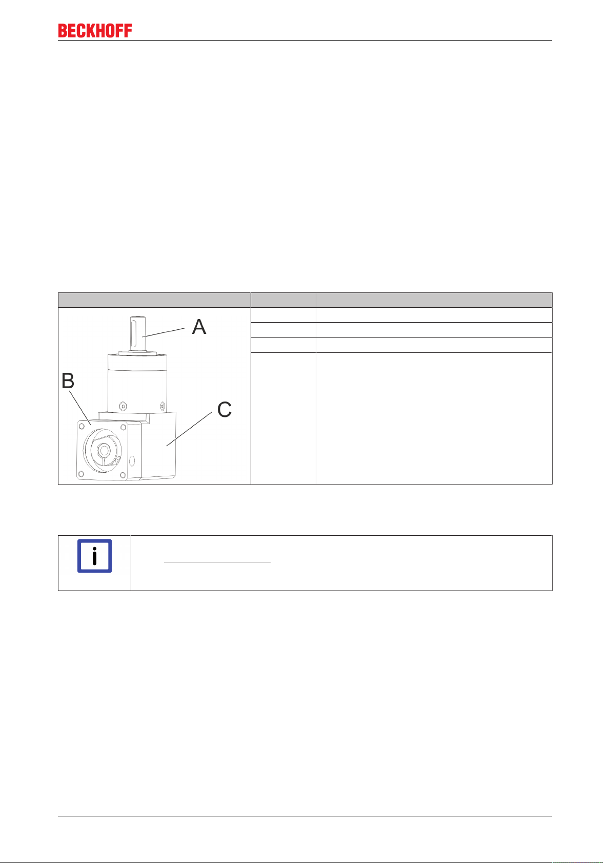
6.2 Overview of PLE gear components
Gear components
A Gear housing
B Output shaft
C Adapter plate
6.3 General technical data
The maximum permissible speeds and torques can be found in our catalog or on our website at http://www.beckhoff.de.
Note
6.4 Transport, assembly and disassembly
Recommendations for trouble-free operation and long service life
• Ensure adequate convection of the gear unit.
Note
Preparing the installation
The drive and output sides are treated with a corrosion inhibitor to protect from corrosion. Ensure that the
installation instructions are enclosed with the gear unit and remove the corrosion inhibitor, once you have
read up on handling hazardous substances.
• Ensure adequate heat dissipation from the gear unit via the output flange.
• The gear unit may heat up due to the motor and other external heat sources. Acquaint
yourself with the motor temperature and external influences that may occur during operation.
• Note the protection class of the gear unit and the resulting constraints.
AG225016 Version: 1.4
Page 17

Mechanical installation, PLE
7 Mechanical installation, PLE
7.1 Important notes
Damage to persons and devices
Observe the general and special safety instructions.
CAUTION
The gear unit can be used in any gear unit.
Assembly sequence
Always follow the assembly sequence described below in order to avoid damage.
Attention
The fastening screws are not included and must be provided by the customer. Pertinent information can be
found in the individual assembly steps.
Compressed air may damage gear unit seals.
Do not use compressed air for cleaning the gear unit.
Attention
In rare cases, leaks ("sweating") may occur at the drive in gear units with
grease lubrication (see type plate).
Attention
• Clean the following components with a clean, lint-free cloth and a grease-dissolving, non-aggressive
cleaning agent:
◦ all surfaces in contact with adjacent components
◦ Centering
◦ the motor shaft
◦ the internal diameter of the socket
◦ the spacer sleeve inside and outside
• In addition, check the contact surfaces for damage and foreign particles.
• To avoid "sweating", we recommend sealing the areas between
ð adapter plate, drive housing and gear unit and
ð adapter plate and motor
ð with a surface seal adhesive (e.g. Loctite® 573 or 574).
• For further information please contact our customer service.
AG2250 17Version: 1.4
Page 18

Mechanical installation, PLE
7.2 Mounting the motor on the gear unit
If a motor is included, it is already installed (no assembly required).
Note
Observe the safety instructions
• Observe the information and safety instructions of the motor manufacturer.
Attention
• Observe the safety and processing instructions for the threadlocker.
Procedure:
• Clean all components to ensure they are grease-free and check
the motor and gear unit for damage prior to assembly.
• Mount the motor in vertical direction, if possible.
• If the motor shaft has a feather key, remove it.
Insert a half wedge, if recommended by the
manufacturer.
• Turn the socket (A) until the set screw (B) is accessible via the
mounting hole.
• Push the motor shaft into the socket of the gear unit.
The maximum permitted axial loads must not be
exceeded.
The motor shaft must slide easily. If this is not the case,
the set screw should be loosened further.
For grooved shafts (H) the slot of the spacer sleeve (F)
must be in line with the groove of the motor shaft and at
right angles with the set screw (B).
There must be no gap between the motor (C) and the
adapter plate (D)
• Coat the four screws (E) with a threadlocker (e.g. Loctite 243). Use screws of strength class 8.8.
• Attach the motor (C) to the adapter plate (D) with the four screws (E). Note that the tightening torque
for the screws should be 90 % (576 Nm) of the yield strength. Tighten the four screws (E) crosswise.
• Tighten the set screw (B) of the socket (A).
• Push the enclosed sealing plug into the mounting hole (I) of the adapter plate (D) up to the end stop.
AG2250 Tightening system Ø
(depends on size) [mm]
040 8 / 9 / 11 2.5 / 3 2 / 4.5 160
060 11 / 14 / 19 3 / 4 4.5 / 9.5 450
Width across flats
of the set screw
(B)
[mm]
Tightening torque
[Nm]
Max. axial force
[N]
AG225018 Version: 1.4
Page 19

7.3 Mounting the gear unit at the machine
Assembly sequence
Before proceeding with the assembly, decide whether to install the attachments on the
drive side first, or the gear unit to the machine first.
Note
Procedure:
The gear housing features four threaded holes for connection with your
machine.
• Thoroughly clean the drive shaft, centering and contact surface.
Screws must be provided by the customer. The specified screw sizes
and tightening torques can be found in the following table.
• Coat the four screws with a threadlocker (e.g. Loctite 243).
• Attach the gear unit to the machine with the four mounting screws
through the screw holes.
Install the gear unit such that the name plate remains
readable.
Do not use washers or toothed washers
Mechanical installation, PLE
Gear size AG2250 Pitch circle Ø [mm] Screw size /
Strength class
040 46 M4 / 12.9 4.55
060 52 M5 / 12.9 9.0
Tightening torque
[Nm]
AG2250 19Version: 1.4
Page 20
Technical data, PLE
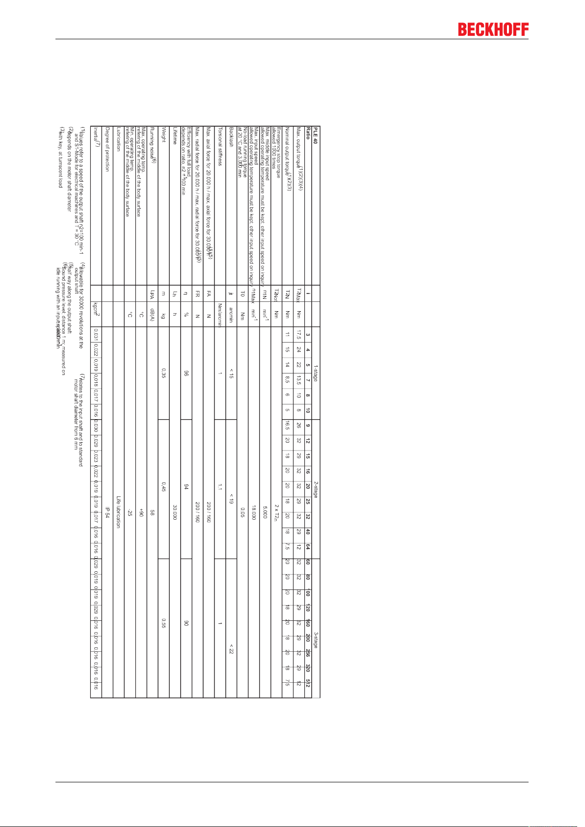
8 Technical data, PLE
8.1 PLE40
AG225020 Version: 1.4
Page 21
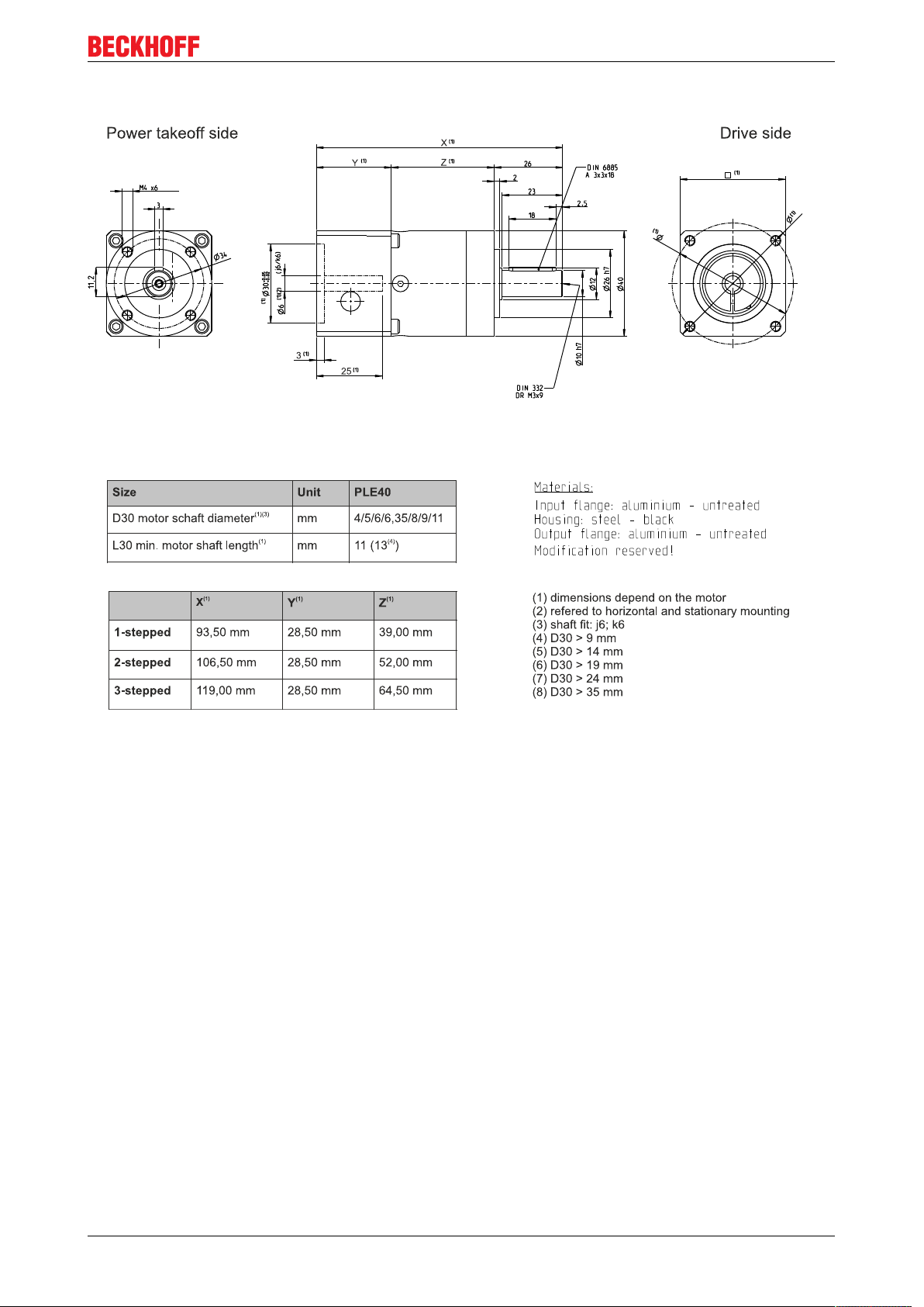
8.1.1 Dimensional drawing, PLE40
Technical data, PLE
AG2250 21Version: 1.4
Page 22

Technical data, PLE
8.2 PLE60
AG225022 Version: 1.4
Page 23

8.2.1 Dimensional drawing, PLE60
Technical data, PLE
AG2250 23Version: 1.4
Page 24

Product ID WPLE
9 Product ID WPLE
9.1 Scope of delivery AG2250-WPLE
• Check the completeness of the delivery against the delivery note.
• Missing parts or damage should be reported immediately in writing to the carrier, the insurance
company and / or Beckhoff Automation.
9.2 Type label AG2250-WPLE
9.3 Type key AG2250-WPLE
AG225024 Version: 1.4
Page 25
Technical description WPLE
10 Technical description WPLE
10.1 Gear unit configuration
The gear units of the AG2250 - WPLExxx series are single- or multi-stage, low-backlash angled planetary
gear units. They can be used in any installation position. All gear units are manufactured in version
"M" (motor mounting) as standard. The gear units are characterized by low torsional backlash, high drive
torques and high efficiency of up to 97%. The gear units are available in 23 gear ratios and are easy to
mount at the motor. All AG2250-WPLExxx gear units are manufactured according to the ISO 9001 quality
standard and lubricated for life. They have a balanced motor pinion.
10.2 Overview of WPLE gear components
The gear unit is a single- or multi-stage, low-backlash planetary gear unit, which can be used in any
installation position.
Gear components
A Output shaft
B Adapter plate
C Gear housing
10.3 General technical data
The maximum permissible speeds and torques can be found in our catalog or on our website at http://www.beckhoff.de.
Note
AG2250 25Version: 1.4
Page 26

Technical description WPLE
10.4 Transport, assembly and disassembly
Recommendations for trouble-free operation and long service life
• Ensure adequate convection of the gear unit.
Note
Preparing the installation
The drive and output sides are treated with a corrosion inhibitor to protect from corrosion. Ensure that the
installation instructions are enclosed with the gear unit and remove the corrosion inhibitor, once you have
read up on handling hazardous substances.
• Ensure adequate heat dissipation from the gear unit via the output flange.
• The gear unit may heat up due to the motor and other external heat sources. Acquaint
yourself with the motor temperature and external influences that may occur during operation.
• Note the protection class of the gear unit and the resulting constraints.
AG225026 Version: 1.4
Page 27

Mechanical installation, WPLE
11 Mechanical installation, WPLE
11.1 Important notes
Damage to persons and devices
Observe the general and special safety instructions.
CAUTION
The gear unit can be used in any gear unit.
Assembly sequence
Always follow the assembly sequence described below in order to avoid damage.
Attention
The fastening screws are not included and must be provided by the customer. Pertinent information can be
found in the individual assembly steps.
Compressed air may damage gear unit seals.
Do not use compressed air for cleaning the gear unit.
Attention
In rare cases, leaks ("sweating") may occur at the drive in gear units with
grease lubrication (see type plate).
Attention
• Clean the following components with a clean, lint-free cloth and a grease-dissolving, non-aggressive
cleaning agent:
◦ all surfaces in contact with adjacent components
◦ Centering
◦ the motor shaft
◦ the internal diameter of the socket
◦ the spacer sleeve inside and outside
• In addition, check the contact surfaces for damage and foreign particles.
• To avoid "sweating", we recommend sealing the areas between
ð adapter plate, drive housing and gear unit and
ð adapter plate and motor
ð with a surface seal adhesive (e.g. Loctite® 573 or 574).
• For further information please contact our customer service.
AG2250 27Version: 1.4
Page 28

Mechanical installation, WPLE
11.2 Mounting the motor on the gear unit
If a motor is included, it is already installed (no assembly required).
Note
Observe the safety instructions
• Observe the information and safety instructions of the motor manufacturer.
Attention
• Observe the safety and processing instructions for the threadlocker.
Procedure:
• Clean all components to ensure they are grease-free and check
the motor and gear unit for damage prior to assembly.
• Mount the motor in vertical direction, if possible.
• If the motor shaft has a feather key, remove it.
Insert a half wedge, if recommended by the
manufacturer.
• Turn the socket (A) until the set screw (B) is accessible via the
mounting hole.
• Push the motor shaft into the socket of the gear unit.
The maximum permitted axial loads must not be
exceeded.
The motor shaft must slide easily. If this is not the case,
the set screw should be loosened further.
For grooved shafts (H) the slot of the spacer sleeve (F)
must be in line with the groove of the motor shaft and at
right angles with the set screw (B).
There must be no gap between the motor (C) and the
adapter plate (D)
• Coat the four screws (E) with a threadlocker (e.g. Loctite 243). Use screws of strength class 8.8.
• Attach the motor (C) to the adapter plate (D) with the four screws (E). Note that the tightening torque
for the screws should be 90 % (576 Nm) of the yield strength. Tighten the four screws (E) crosswise.
• Tighten the set screw (B) of the socket (A).
• Push the enclosed sealing plug into the mounting hole (I) of the adapter plate (D) up to the end stop.
AG2250 Tightening system Ø
(depends on size)
[mm]
040 8 / 9 2.5 / 3 2 / 4.5 160
060 11 / 14 3 4.5 450
Width across flats
of the set screw
(B)
[mm]
Tightening torque
[Nm]
Max. axial force
[N]
AG225028 Version: 1.4
Page 29

11.3 Mounting the gear unit at the machine
Assembly sequence
Before proceeding with the assembly, decide whether to install the attachments on the
drive side first, or the gear unit to the machine first.
Note
Procedure:
The gear housing features four threaded holes for connection with your
machine.
• Thoroughly clean the drive shaft, centering and contact surface.
Screws must be provided by the customer. The specified screw sizes
and tightening torques can be found in the following table.
• Coat the four screws with a threadlocker (e.g. Loctite 243).
• Attach the gear unit to the machine with the four mounting screws
through the screw holes.
Install the gear unit such that the name plate remains
readable.
Do not use washers or toothed washers
Mechanical installation, WPLE
Gear size AG2250 Pitch circle Ø [mm] Screw size /
Strength class
040 34 M4 / 12.9 4.55
060 52 M5 / 12.9 9.0
Tightening torque
[Nm]
AG2250 29Version: 1.4
Page 30
Technical data, WPLE
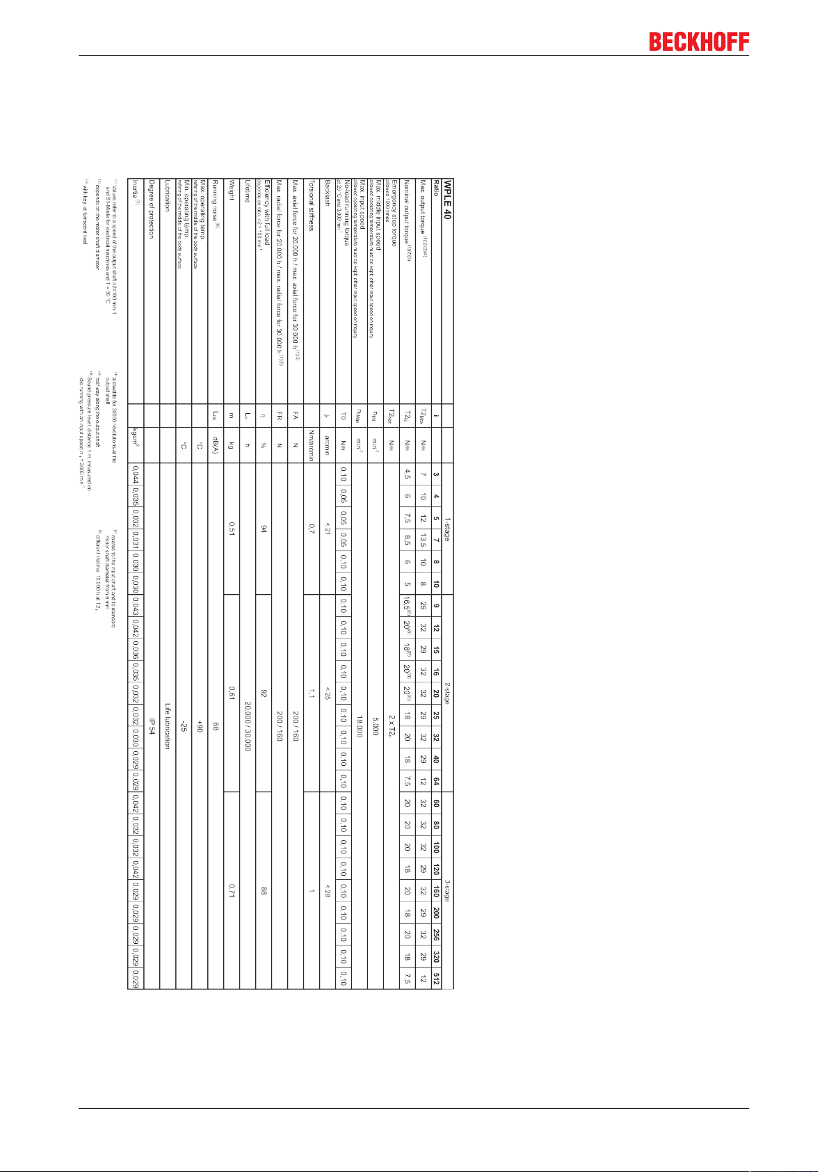
12 Technical data, WPLE
12.1 WPLE40
AG225030 Version: 1.4
Page 31

12.1.1 Dimensional drawing, WPLE40
Technical data, WPLE
AG2250 31Version: 1.4
Page 32

Technical data, WPLE
12.2 WPLE60
AG225032 Version: 1.4
Page 33

12.2.1 Dimensional drawing, WPLE60
Technical data, WPLE
AG2250 33Version: 1.4
Page 34

Commissioning
13 Commissioning
13.1 Important notes
Damage to persons and devices
• Read up on the general and special safety instructions before starting the work.
CAUTION
Improper operation may result in damage to the gear unit.
• Please ensure that
Attention
DANGER
ð the ambient temperature is not below -30 °C and not above +60 °C, and
ð the operating temperature does not exceed +90 °C.
• Avoid icing, which can damage the seals.
• For other operating conditions please contact our customer service.
• Do not exceed the operational limit values for the gear unit
• Only use the gear unit in a clean, dust-free and dry environment.
Serious risk of injury!
• Only specialist personnel with extensive knowledge in the areas of electrical engineering / drive technology are allowed to install and commission the equipment.
• Check that all live connection points are protected against accidental contact. Dangerous voltages can occur, up to 875 VDC.
• Due to the DC link capacitors, the DC link contacts "ZK+ and ZK- (DC+ and DC-)" and
"RB+ and RB-" may be subject to dangerous voltages exceeding 875 VDC, even after
the servo drive was disconnected from the mains supply. Wait 5 minutes for the
AX5101 - AX5125 and AX520x; 15 minutes for the AX5140/AX5160/AX5172; 30 minutes for the AX5190/AX5191; 45 minutes for the AX5192/AX5193 after disconnecting,
and measure the voltage at the DC links "ZK+ and ZK- (DC+ and DC-)". The device is
safe once the voltage has fallen below 50 V.
• The surface temperature of the motor can exceed 100 °C in operation. Check (measure) the temperature of the motor. Wait until the motor has cooled down below 40 °C
before touching it.
• Make sure that, even if the drive starts to move unintentionally, no danger can result for
personnel or machinery.
Attention
Overloading of the gear!
With motor / gear combinations can in case of failure (mechanical blockage of the power
train) due to high ratio, the gear will be overloaded.
To prevent this, make sure that the motor rated torque and the motor peak torque is
limited in the servo drive.
Example:
• Motor rated torque / motor peak torque: 1 Nm / 5 Nm
• Gear rated torque / gear peak torque: 15 Nm / 24 Nm
• Gear ratio: i = 10
• The motor rated torque is not limited. The motor peak torque is limited to 2,4 Nm.
AG225034 Version: 1.4
Page 35

Commissioning
13.2 Guide for commissioning the gear units
The procedure for commissioning is described as an example.
A different method may be appropriate or necessary, depending on the application of the equipment.
• Check the assembly and alignment of the motor and the gear unit.
• Check the drive components such as clutch, gear unit, belt pulley and gear unit for correct seating and
setting (observe the permissible radial and axial forces).
• Check the wiring and connections at the motor, servo drive and gear unit. Check that the earthing is
correct.
• Test the function of the holding brake, if used. (Apply 24VDC, the brake must release).
• Check whether the rotor of the motor revolves freely (release the brake, if necessary). Listen out for
grinding noises from the motor and the gear unit.
• Check that all the required measures against accidental contact with live and moving parts have been
carried out.
• Carry out any further checks which are specifically required for your system.
• Now commission the drive according to the commissioning instructions for the servo drive.
• In multi-axis systems, individually commission each drive unit (servo drive/motor(s)).
• During the installation and commissioning look out for chips or similar contaminants that may penetrate
into the gear unit. Keep the work area clean and protect the gear unit from foreign objects. Penetration
of dirt reduces the service life of the gear unit.
Note
Destruction of the gear unit due to maximal engine torque!
Before commissioning, check that your configured max. engine torque does not destroy the
gear unit. For further information, please refer to chapter 13.1: "Important notes [}34]".
AG2250 35Version: 1.4
Page 36

Commissioning
13.3 Troubleshooting
Changed operating behavior
A change in operating behavior may indicate existing damage of the gear unit or result in
Attention
CAUTION
Error Possible cause Remedy
Increased operating temperature The gear unit is not suitable for the
Increased operating noises Distorted motor mounting Contact our service department.
Lubricant loss Lubricant quantity too high Wipe off the leaking lubricant and
damage to the gear unit.
• Do not recommission the gear unit until the fault has been rectified.
Personal injuries
Troubleshooting may only be performed by trained personnel.
Check the technical data.
purpose.
Motor heats up the gear unit. Check the wiring of the motor.
Ensure adequate cooling.
Change the motor.
Ambient temperature too high. Ensure adequate cooling.
Bearing damage
Gear tooth damage
Toothed belt tension too high
continue to monitor the gear unit.
Lubricant discharge should stop
after a short time.
Leaks Contact our service department.
AG225036 Version: 1.4
Page 37

14 Decommissioning
Damage to persons and devices
• Read up on the general and special safety instructions before starting the work.
CAUTION
Decommissioning
AG2250 37Version: 1.4
Page 38

Support and Service
15 Support and Service
Beckhoff and their partners around the world offer comprehensive support and service, making available fast
and competent assistance with all questions related to Beckhoff products and system solutions.
Beckhoff's branch offices and representatives
Please contact your Beckhoff branch office or representative for local support and service on Beckhoff
products!
The addresses of Beckhoff's branch offices and representatives round the world can be found on her internet
pages:
http://www.beckhoff.com
You will also find further documentation for Beckhoff components there.
Beckhoff Headquarters
Beckhoff Automation GmbH & Co. KG
Huelshorstweg 20
33415 Verl
Germany
Phone: +49(0)5246/963-0
Fax: +49(0)5246/963-198
e-mail: info@beckhoff.com
Beckhoff Support
Support offers you comprehensive technical assistance, helping you not only with the application of
individual Beckhoff products, but also with other, wide-ranging services:
• support
• design, programming and commissioning of complex automation systems
• and extensive training program for Beckhoff system components
Hotline: +49(0)5246/963-157
Fax: +49(0)5246/963-9157
e-mail: support@beckhoff.com
Beckhoff Service
The Beckhoff Service Center supports you in all matters of after-sales service:
• on-site service
• repair service
• spare parts service
• hotline service
Hotline: +49(0)5246/963-460
Fax: +49(0)5246/963-479
e-mail: service@beckhoff.com
AG225038 Version: 1.4
 Loading...