

Page 1

B-Tronic VarioControl
VC4200B
en
Assembly and Operating Instructions
Flush-mounted radio receiver
Important information for:
• Fitters / • Electricians / • Users
Please forward accordingly!
These instructions must be kept safe for future reference.
4035 630 040 0d13/02/2018
Becker-Antriebe GmbH
Friedrich-Ebert-Straße 2-4
35764 Sinn/Germany
www.becker-antriebe.com
Page 2

Table of contents
General ................................................................................................... 3
Warranty ................................................................................................. 3
Safety instructions ................................................................................... 4
Intended use ........................................................................................... 5
Explanation of displays and buttons........................................................... 6
Wiring ..................................................................................................... 9
Programming transmitters .......................................................................12
Limit position adjustment and configurations.............................................13
Deleting transmitters............................................................................... 14
Restoring to factory settings ....................................................................14
Technical data for the flush-mounted radio receiver...................................15
What to do if...?.......................................................................................16
Simplified EU declaration of conformity.....................................................17
2
Page 3
General
The flush-mounted radio receiver, delivered ex works, converts radio signals
into control signals. A wired drive can be radio-controlled using the radio receiver. The radio receiver can be operated by all the transmitters in the BTronic range of control units.
Please observe these Assembly and Operating Instructions when installing
and setting up the equipment.
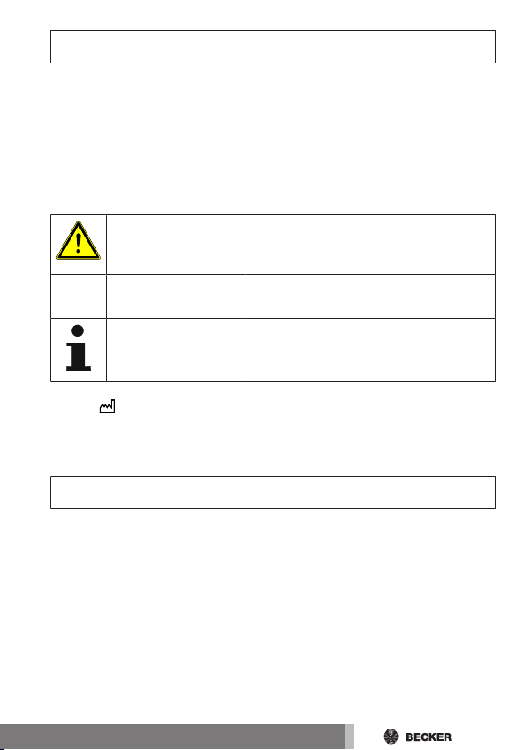
Explanation of pictograms
CAUTION
ATTENTION
You will find the current status on the type plate according to the following
symbol:
Confirmation is provided by the receiver switching briefly on and off, or by a
shift in the shading solution.
CAUTION indicates a hazardous situation
which, if not avoided, could result in injury.
ATTENTION indicates measures that must
be taken to avoid damage to property.
Denotes user tips and other useful information.
Warranty
Structural modifications and incorrect installation which are not in accordance
with these and our other instructions can result in serious injuries, e.g., crushing of limbs. Therefore, structural modifications may only be carried out with
our prior approval and strictly in accordance with our instructions, particularly
the information contained in these Assembly and Operating Instructions.
Any further processing of the products which does not comply with their intended use is not permitted.
The end product manufacturer and fitter have to ensure that all the relevant
current statutory, official and, in particular, EMC regulations are adhered to
during utilisation of our products, especially with regard to end product manufacture, installation and customer advice.
3
Page 4

Safety instructions
The following safety instructions and warnings are intended to avert hazards
and to prevent property damage and personal injury.
General information
• Always comply with regulations of local energy supply companies as well
as VDE 100 provisions for wet and damp rooms during installation.
• Only use in dry rooms.
• Only use unmodified original parts from the control unit manufacturer.
• Observe all pertinent country-specific regulations.
• Keep people out of the system’s range of travel.
• If the system is controlled by one or several appliances, the system’s
range of travel must always be visible during operation.
• Keep children away from control units.
Caution
• Risk of injury due to electric shock.
• Connections to the 110-240V mains must always be per-
formed by a specialist.
• During installation, all-pole disconnection from the mains
with a contact gap of at least 3mm per pole must be
provided.
• Disconnect the connecting cable from the power prior to
installation.
• When connecting the control cables (protected extra-low
voltages), only use cables with sufficient electrical
strength.
• A wind monitoring unit cannot be connected to the
device. Retract the exterior sun protection manually in
strong winds in order to prevent damage.
4
Page 5

Intended use
The radio receiver described by the present instructions must only be used for
the operation of roller shutter, blind and ON/OFF control units (e.g. lighting
equipment).
• Please note that radio-controlled systems may not be used in areas with
a high risk of interference (e.g. hospitals, airports).
• The remote control is intended solely for use with equipment and systems in which malfunctions in the transmitter or receiver would not pose
any risk to persons, animals or property, or which contain safety devices
to eliminate such risks.
• The operator is not protected from interference from other telecommunications systems and terminal equipment (e.g. even from radio-controlled systems which are properly operated in the same frequency
range).
• Only connect radio receivers to devices and systems approved by the
manufacturer.
• Ensure that the control unit is not installed or operated
close to metal surfaces or magnetic fields.
• Radio-controlled systems transmitting on the same frequency may cause reception interference.
• Note that the range of the radio signal is limited by legislation as well as by design.
5
Page 6
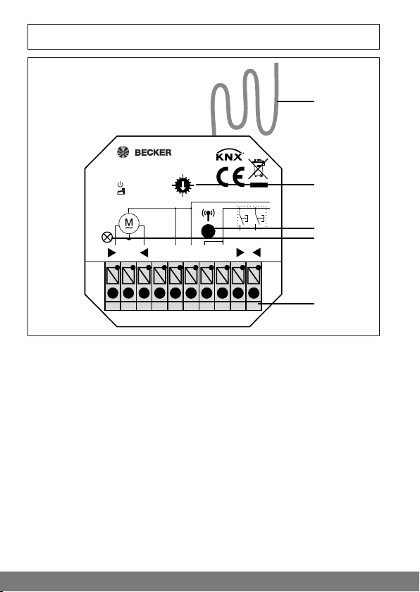
Explanation of displays and buttons
L
Ind.
Ind.
L N
N
C
N
L
8
4 21
0
B-Tronic VarioControl VC4200B
4035 200 032 0
110-240V/50-60Hz
IP200,7W
1627
µ 3 A
110-240V~
1
2
3
4
5
6
Page 7

1. Antenna
2. Function selection switch
(Positions 0-15)
3. Programming button
4. LED
5. Connecting terminals
Position 0 Reference (LED briefly
Position 1 Roller shutter (current
Position 2 Venetian blind (current
Position 3 ON/OFF
Position 4 ON and OFF after 10
Position 5 ON and OFF after 3
Position 6 Pulse (1 second)
Position 7 Pulse (3 seconds)
Position 8 Roller shutter (current
Position 9 Venetian blind (current
Positions
10-15
lights up red)
detection active)
detection active)
minutes
minutes
detection inactive)
detection inactive)
Not assigned
To be able to program the transmitter and receiver, the function of both devices must correspond.
7
Page 8

Extra functions
Function
Roller shutter
Venetian blind
ON/OFF
ON and OFF after 10 minutes
ON and OFF after 3 minutes
Pulse (1 second)
Pulse (3 seconds)
= present
= optional
8
Intermediate position I / tilt
position I
Intermediate position II / tilt
position II
Memory function
Repeater
Reversal of rotational direction
using master transmitter
Current detection
Page 9

Wiring
Caution
• Risk of injury due to electric shock.
• Connection may only be performed by a qualified electri-
cian!
• The device only offers back-of-hand protection, not
touch protection.
• Do not bend, shorten or lengthen the antenna.
• Only operate the programming button with an insulated
tool.
• If more than one drive is going to be operated by the radio
receiver, the drives must be decoupled by relay controls.
There is no need for decoupling in the case of our drives
with electronic limit switching.
• Always take into account the device switching current.
• The maximum switching capacity must not be exceeded.
• When the jumper is inserted (C to L), the mains voltage is
switched to the outputs of the radio receiver.
9
Page 10

Individual inputs
Ind.
Ind.
with drive control
These connecting terminals are intended for an additional button. If a travel
button is pressed for more than 0.5 seconds, the shading solution runs in the
desired direction as far as the limit position. If the travel button is pressed for
less than 0.5 seconds, the shading solution stops.
If intermediate positions have been programmed, these can be approached
using the push-button by tapping UP / DOWN twice.
Ensure that there is optimum radio reception.
Drive connection
10
Page 11

Individual inputs
Ind.
Ind.
with ON/OFF control
When connecting the individual terminal on the left
This connecting terminal is for an additional push-button. Pressing the button
for longer than 0.5 seconds switches on the device. Pressing the button again
switches off the device.
When connecting the individual terminal on the right
This connecting terminal is for an additional push-button. Pressing the button
enables the pulse sequence ON-OFF-ON-OFF, etc.
ON/OFF control unit connection (e.g. lighting)
The "left" terminal is not connected.
11
Page 12

Programming transmitters
Caution
• Risk of injury due to electric shock.
• The device only offers back-of-hand protection, not
touch protection.
• Only operate the programming button with an insulated
tool.
Putting the radio receiver into programming mode
a) Putting the radio receiver into programming mode by switching on
the power
If you select position 0 (reference) via the function switch
after programming, the function that was previously set is
saved. It is now no longer possible to activate programming
mode by switching on the voltage.
Select the required function via the function switch (see Explanation of displays and buttons [}6]).
Switch on the power.
The LED flashes green.
► The radio receiver goes into the programming mode for 3 minutes.
b) Putting the radio receiver into programming mode with the programming button
Select the required function via the function switch (see Explanation of displays and buttons [}6]).
Press the programming button for 1 second.
The LED flashes green.
► The radio receiver goes into the programming mode for 3 minutes.
c) Putting the radio receiver into programming mode with a previously
programmed B-Tronic transmitter
Select the required function via the function switch (see Explanation of displays and buttons [}6]).
For a more detailed description refer to the instructions for the transmitter.
12
Page 13

Limit position adjustment and configurations
The commissioning and later configurations are only possible with a B-Tronic
transmitter.
1. Setting of limit positions
Please find the appropriate description in the instructions for the drive.
2. Performing the programming run
Feedback is disabled and it is not possible to program the intermediate positions until the programming run has been performed.
Please find the information on how to perform the programming run in the instructions for the B-Tronic transmitter.
3. Possible configurations
Please find the appropriate description in the instructions for the B-Tronic
transmitter.
• Intermediate positions I+II
• Memory function
• Repeater mode
13
Page 14

Deleting transmitters
Deleting a transmitter via the radio receiver
Caution
• Risk of injury due to electric shock.
• The device only offers back-of-hand protection, not
touch protection.
• Only operate the programming button with an insulated
tool.
Select the required function via the function switch (see Explanation of displays and buttons [}6]).
Press the programming button at the radio receiver for 5 seconds until the LED
at the radio receiver flashes red.
For a more detailed description refer to the instructions for the transmitter.
Deleting a transmitter via a programmed B-Tronic
transmitter
Please find the appropriate description in the instructions for the B-Tronic
transmitter.
Restoring to factory settings
Select position 0 at the function switch.
Press the programming button at the radio receiver (for approx. 15 s) until the
LED at the radio receiver flashes green again.
Now all programmed transmitters have been deleted.
14
Page 15

Technical data for the flush-mounted radio
receiver
Rated voltage 110-240V AC / 50-60Hz
Switching current
Current detection threshold at roller
shutter/venetian blind
Degree of protection IP20
Class of protection
(dependent on correct assembly)
Permissible ambient temperature -25 to +55 °C
Roller shutter running time 2 min.
Venetian blind running time 3 min.
Type of mounting Flush mounted Ø 58 mm, wall moun-
Maximum emitted transmission output
Radio frequency 868.3 MHz
The maximum transmitter range on and in the building is up to 25m, and up to
350m in the open.
3A / 110-240V AC with cos =1
>250mA at 50-60Hz
II
ted/surface mounted in appropriate
surface mounted housing
≤ 25 mW
15
Page 16

What to do if...?
Problem Remedy
Drive is not functioning. Check connection.
Drive is running in the wrong direction.
The radio receiver does not perform
manual run commands.
The radio receiver does not perform
automatic run commands.
Intermediate position I / II cannot be
programmed.
Programming failed. Set the same function at the trans-
The feedback is not plausible (function switch in position 1, 2, 8 or 9)
The feedback is not plausible (function switch in position 1 or 2)
The intermediate position/tilt position is not moved to correctly (function switch in position 8 or 9)
Swap the and wires at the radio
receiver.
Program transmitter.
Connect the external button correctly.
Program transmitter.
Set the transmitter to automatic
mode.
Perform the programming run in accordance with the instructions for the
B-Tronic transmitter.
mitter and receiver.
Delete and restart the programming
run in accordance with the instructions for the B-Tronic transmitter.
Reset the radio receiver back to the
factory setting. Depending on the
shading solution, set the function
switch to position 8 or 9. Put the
device back into operation.
Always move to the intermediate position/tilt position from the corresponding limit position.
16
Page 17

Simplified EU declaration of conformity
Becker-Antriebe GmbH hereby declares that this radio control system complies with Directive 2014/53/EU.
The full text of the EU declaration of conformity is available at the following
web address:
www.becker-antriebe.com/ce
Subject to technical changes without notice.
171819
Page 18

Page 19

Page 20

 Loading...