


FALCON & FALCON XL
USER'S GUIDE
MOTION SENSORS FOR INDUSTRIAL DOORS
• FALCON: for high mounting • FALCON XL: for low mounting
TECHNICAL SPECIFICATIONS
Technology: Microwave and microprocessor
Transmitter frequency: |
|
24.125 GHz |
Transmitter radiated power: <20 dBm EIRP |
||
Transmitter power density: |
< 5 mW/cm² |
|
Mounting height |
|
|
FALCON: from 11.5 to 23’ |
|
|
FALCON XL: from 6.5 to 11.5’ |
||
Tilt angle: |
0° to 180° in elevation |
|
Detection zone (typical) |
|
|
Wide pattern (FALCON XL): 13’ (W) x 6.5’ (D) |
||
|
for a mounting height of 8.2’ |
Narrow pattern (FALCON): 13’ (W) x 16’ (D) |
|
|
for a mounting height of 16’ |
Detection mode: |
movement |
Minimum detection speed: 2.2 in/s (measured in the
|
sensor axis) |
Supply voltage: |
12V to 24V AC +/- 10% |
|
12V to 24V DC +30% / -10% |
Mains frequency: |
50 to 60 Hz |
Power consumption: |
< 2W |
Output relay: free of potential changeover contact Max contact voltage : 42V AC/ DC
Max contact current: 1A (resistive)
Max switching power: 30W (DC) / 60 VA (AC)
Hold time: 0.5s to 9s (adjustable)
Manual adjustment:
•orientation of sensing field (mechanically)
•multiple functions (by push buttons).
Remote control adjustments:
•Sensitivity.
•Hold time.
•Detection mode.
•Pedestrian and parallel traffic rejection mode.
•Relay configuration.
Temperature range : -22°F to 122°F (-30°C to +60°C)
Degree of protection: IP65
Product conformity:
R&TTE 1999/5/EC
EMC 89/336/EEC
Dimensions : 5 in (D) x 4 in (W) x 3 ¾ (H)
(127mm (D) x 102 mm (W) x 96mm (H))
Weight: |
0.88 lbs (400 g) |
Housing Material: |
ABS and Polycarbonate |
Bracket Material: |
black anodized aluminum |
Cable length: |
33 ft (10 m) |
Cable diameter: |
1/8” (3 mm) (minimum) |
|
1/4” (6.5 mm) (maximum) |
DESCRIPTION OF THE SENSOR
INSTALLATION
TIPS
The sensor must be firmly fastened in order not to vibrate.
The sensor must not be placed directly behind a panel or any kind of material.
The sensor must not have any object likely to move or vibrate in its sensing field.
The sensor must not have any fluorescent lighting in its sensing field.
75.5351.02 EN 20080317 (75.5350) |
Page 1 of 7 |

WIRING
US Wire Color: Red |
Black |
White |
Green |
Yellow |
12-24 |
VAC/DC |
COM |
NO |
NC |
European Wire Color: Brown |
Green |
White |
Yellow |
Gray |
|
|
|
|
|
To remove or to insert the cable:
•Unscrew the retaining nut;
•Pass the cable through the grommet and the retaining nut.
•Tighten the retaining nut.
OPENING AND |
Opening the sensor |
|
Closing the sensor |
||
|
|
|
|
|
|
|
|
|
|
|
|
CLOSING THE |
|
|
|
|
|
SENSOR |
|
|
|
|
|
|
|
|
|
|
|
|
|
|
|
|
|
SENSOR DIMENSIONS AND MOUNTING
BRACKET MOUNTING
• Loosen the retaining nut |
• Connect the quick disconnect terminal block to the main |
||||||||||||||||||||||
until the cable slides easily into the |
electronic circuit; |
|
|
|
|
|
|
|
|||||||||||||||
grommet; |
• Slide the main electronic circuit into the 2 housing slot |
||||||||||||||||||||||
• Partially unscrew the 2 front cover |
guides; |
|
|
|
|
|
|
|
|||||||||||||||
screws; |
• Gently push the front cover and make sure that the external |
||||||||||||||||||||||
• Pull out the front cover with the 2 |
housing is properly seated (front cover must be flush with |
||||||||||||||||||||||
front cover screws. |
housing). |
|
|
|
|
|
|
|
|||||||||||||||
|
|
|
|
|
|
|
|
|
|
|
• Screw the 2 front cover screws and tighten the retaining nut. |
||||||||||||
|
|
|
Ceiling Mounting |
|
|
|
|
|
|
Wall Mounting |
|||||||||||||
|
|
|
|
|
|
|
|
|
|
|
|
|
|
|
|
|
|
|
|
|
|
|
|
|
|
|
|
|
|
|
2.5 in |
|
|
|
|
|
|
|
|
|
|
|
|
|
|
|
|
|
|
|
|
|
|
|
|
|
|
|
|
|
|
|
|
|
|
|
|||||
|
|
|
|
|
|
|
|
|
|
|
|
|
|
|
|
|
|
|
|
3 in |
|
||
|
|
|
|
|
|
|
|
|
|
|
|
|
6 in |
|
5.5 in |
|
|
|
|
|
|
|
|
|
|
6.5 in |
|
6 in |
|
|
|
|
|
|
|
|
|
||||||||||
|
|
|
|
|
|
|
|
|
|
|
|
|
|
|
|
||||||||
|
|
|
|
|
|
|
|
|
|
|
|
|
|
|
|
|
|
|
|
|
|
|
|
|
|
|
|
|
|
|
|
|
|
|
|
|
|
|
|
|
|
|
|
|
|
|
|
|
|
|
|
|
|
|
|
|
|
|
|
|
|
|
|
|
|
|
|
|
|
|
|
|
|
|
|
|
|
|
|
|
|
|
|
|
|
|
|
|
|
|
5 in |
||||
|
|
|
|
|
|
5 in |
|
|
|
|
|
|
|
|
|
|
|
|
|
|
|
||
|
|
|
|
|
|
|
|
|
|
|
|
|
|
|
|
|
|
6.25 in |
|
|
|||
|
|
|
|
|
|
|
|
|
|
|
|
|
|
|
|
|
|||||||
|
|
|
|
|
|
6.25 in |
|
|
|
|
|
|
|
|
|
||||||||
|
|
|
|
|
|
|
|
|
|
|
|
|
|
|
|
|
|
|
|
|
|
||
|
|
|
|
|
|
|
|
|
|
|
|
|
|
|
|
|
|
|
|
|
|
|
|
Remark: The bold-type values give the minimum distance required to be able to fully adjust the sensor.
• Check that both locking collar are at the same angle;
• Align the bracket slot to the locking collar guide as shown.
75.5351.02 EN 20080317 (75.5350) |
Page 2 of 7 |
SETTING |
|
|
|
|
|
|
|
|
FALCON (Mounting height: 16.5 feet) |
|
|
|
|
|
|
|
|
|||||||||
THE SENSING |
|
|
|
|
|
|
|
|
|
|
|
|
|
|
|
|
|
|
|
|
|
|
|
|
|
|
FIELD |
|
|
|
|
6 |
3 |
0 |
3 |
6 |
|
|
|
|
|
|
|
6 |
3 |
0 |
3 |
6 |
|
|
|
|
|
|
|
|
|
|
|
|
|
|
|
|
|
|
|
|
|
|
|
|
|
|
||||||
|
|
|
|
|
|
|
|
|
|
|
|
|
|
|
|
|
|
|
|
|
|
|
|
|
|
|
|
|
|
|
|
|
|
|
|
|
|
|
|
|
|
|
|
|
|
|
|
|
|
|
|
|
|
DIMENSIONS |
|
|
|
|
|
|
|
|
|
|
|
|
|
|
|
|
|
|
|
|
|
|
|
|
|
|
|
|
3 |
|
|
|
|
|
|
|
|
3 |
|
|
|
|
|
|
|
|
|
|
|
|
|
|
|
|
|
|
|
|
|
|
|
|
|
|
|
|
|
3 |
|
|
|
|
|
|
|
3 |
|
|||
|
|
|
|
|
|
|
|
|
|
|
|
|
|
|
|
|
|
|
|
|
|
|
||||
|
|
|
6 |
|
|
|
|
|
|
|
6 |
|
|
|
6 |
|
|
|
|
|
|
|
6 |
|
||
|
|
|
|
|
|
|
|
|
|
|
|
|
|
|
|
|
|
|
|
|
|
|
||||
|
|
|
9 |
|
|
|
|
|
|
|
9 |
|
|
|
9 |
|
|
|
|
|
|
|
9 |
|
||
|
|
|
|
|
|
|
|
|
|
|
|
|
|
|
|
|
|
|
|
|
|
|
||||
|
|
|
12 |
|
|
|
|
|
|
|
12 |
|
|
|
12 |
|
|
|
|
|
|
|
12 |
|
||
|
|
|
|
|
|
|
|
|
|
|
|
|
|
|
|
|
|
|
|
|
|
|
||||
The sensing fields here on the |
|
15 |
|
|
|
|
|
|
|
15 |
|
The sensing fields here on the |
|
15 |
|
|
|
|
|
|
|
15 |
|
|||
|
|
|
|
|
|
|
|
|
|
|
|
|
|
|
|
|
|
|
|
|||||||
|
|
|
|
|
|
|
|
|
|
|
|
|
|
|
|
|
|
|
|
|
|
|
|
|||
right correspond to the |
|
18 |
|
|
|
|
|
|
|
18 |
|
right correspond to the following |
|
18 |
|
|
|
|
|
|
|
18 |
|
|||
following adjustments: |
|
|
|
|
|
|
|
|
|
|
|
|
adjustments: |
|
|
|
|
|
|
|
|
|||||
|
|
|
|
|
|
|
|
|
|
|
|
|
|
|
|
|
|
|
|
|
|
|
|
|||
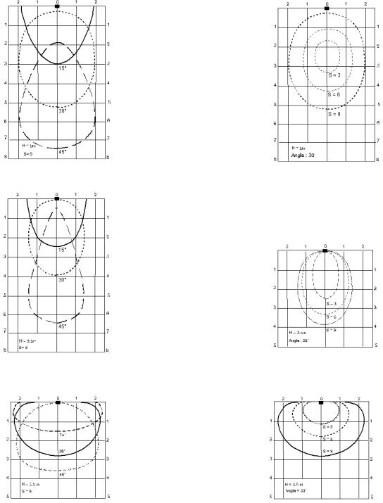
• tilt angle: 15°, 30°, 45° |
|
21 |
|
|
|
|
|
|
|
21 |
|
• tilt angle: 30° |
|
21 |
|
|
|
|
|
|
21 |
|
||||
|
|
|
H = 16.5 ft. |
|
|
|
|
|
|
|
|
|||||||||||||||
• sensitivity: 9. |
|
|
|
|
|
|
|
|
|
|
• sensitivity: 9, 6, 3 |
|
|
|
|
H = 16.5 ft. |
|
|
|
|
|
|
|
|||
|
|
|
|
S = 9 |
|
|
|
|
|
|
|
|
|
|
|
|
|
|
|
|
|
|
||||
|
|
|
|
|
|
|
|
|
|
|
|
|
|
|
Angle = 30° |
|
|
|
|
|
|
|
||||
|
|
|
|
|
|
|
|
|
|
|
|
|
|
|
|
|
|
|
|
|
|
|
|
|
|
|
|
|
|
|
|
|
|
|
|
|
|
|
|
|
|
|
|
|
|
|
|
|
|
|
|
|
|
|
|
|
|
|
|
|
|
|
|
|
|
|
|
|
|
|
|
|
|
|
|
|
|
|
|
|
|
|
|
|
|
|
|
|
|
|
|
|
|
|
|
|
|
|
|
|
|
|
|
|
|
|
|
FALCON (Mounting height: 11.5 feet)
|
|
|
|
|
|
|
|
|
|
|
|
|
|
|
|
|
|
|
6 |
3 |
0 |
3 |
6 |
|
|
|
|
|
|
|
|
|
|
|
|
|
|
|
|
|
|
|
3 |
|
|
|
|
|
|
|
|
|
|||
|
|
|
|
|
|
|
|
|
|
|
3 |
|
|
|
|
|
6 |
|
|
|
|
|
|
|
6 |
|
|
|
|
|
9 |
|
|
|
|
|
|
|
9 |
|
|
|
|
|
12 |
|
|
|
|
|
|
|
12 |
|
|
|
|
|
15 |
|
|
|
|
|
|
|
15 |
|
|
The sensing fields here on the |
|
|
|
|
|
|
|
|
|
|
|
|
|
right correspond to the |
|
|
18 |
|
|
|
|
|
|
|
18 |
|
|
following adjustments: |
|
|
21 |
|
|
|
|
|
|
|
|
21 |
|
• tilt angle: 15°, 30°, 45° ; |
|
|
|
|
|
|
|
|
|
|
|||
|
|
|
|
|
H = 11.5 ft. |
|
|
|
|
|
|
||
• sensitivity: 9. |
|
|
|
|
|
S = 9 |
|
|
|
|
|
|
|
|
|
|
|
|
|
|
|
|
|
|
|
|
|
|
|
|
|
|
|
|
|
|
|
|
|
|
|
|
|
|
|
|
|
|
|
|
|
|
|
|
|
The sensing fields here on the right correspond to the following adjustments:
•tilt angle: 30°
•sensitivity: 9, 6, 3
|
|
|
|
|
|
|
|
|
|
|
6 |
3 |
0 |
3 |
6 |
|
|
|
|||
|
|
|
|
|
|
|
|
|
|
|
|
3 |
|
|
|
|
|
|
3 |
|
|
|
6 |
|
|
|
|
|
|
6 |
|
|
|
9 |
|
|
|
|
|
|
9 |
|
|
|
12 |
|
|
|
|
|
|
12 |
|
|
|
H = 11.5 ft. |
|
|
|||||||
|
|
|
|
|
|
|
|
|
|
|
|
15 |
|
|
Angle = 30° |
|
|
|
|
|
|
|
|
|
|
|
|
|
15 |
|
||
|
|
|
|
|
|
|
|
|
|
|
FALCON XL (Mounting height: 8 feet)
The sensing fields here on the right correspond to the following adjustments:
•tilt angle: 15°, 30°, 45° ;
•sensitivity: 9.
|
|
|
|
|
|
|
|
|
|
|
6 |
3 |
0 |
3 |
6 |
|
|
|
|||
|
|
|
|
|
|
|
|
|
|
|
|
3 |
|
|
|
|
|
|
3 |
|
|
|
6 |
|
|
|
|
|
|
6 |
|
|
|
9 |
|
|
|
|
|
|
9 |
|
|
|
12 |
|
|
|
|
|
|
12 |
|
|
|
H = 8 ft. |
|
|
|||||||
|
|
|
|
|
|
|
|
|
|
|
|
15 |
|
|
S = 9 |
|
|
|
|
|
|
|
|
|
|
|
|
|
15 |
|
||
|
|
|
|
|
|
|
|
|
|
|
|
|
|
|
|
|
|
|
|
|
|
|
|
6 |
3 |
0 |
3 |
6 |
|
|
|
|||
|
|
|
|
|
|
|
|
|
|
|
|
|
|
3 |
|
|
|
|
|
|
3 |
|
|
|
|
6 |
|
|
|
|
|
|
6 |
|
|
The sensing fields here on the |
|
|
|
|
|
|
|
|
|
|
|
right correspond to the |
|
9 |
|
|
|
|
|
|
9 |
|
|
following adjustments: |
|
|
|
|
|
|
|
|
|
|
|
• tilt angle: 30° |
|
12 |
|
|
|
|
|
|
12 |
|
|
|
H = 8 ft. |
|
|
||||||||
|
|
|
|
|
|
|
|
|
|
||
• sensitivity: 9, 6, 3 |
|
15 |
|
|
Angle = 30° |
|
|
|
|
15 |
|
|
|
|
|
|
|
|
|
|
|||
|
|
|
|
|
|
|
|
|
|
|
|
LED SIGNAL |
• When the power is turned ON, the red and green LEDs flash for few seconds. |
|
• During a detection the red LED lights on. |
|
|
|
• During configuration, the red LED flashes a number of times corresponding to the parameter being |
|
changed (see next table). The green LED flashes a number corresponding to its setting. |
75.5351.02 EN 20080317 (75.5350) |
Page 3 of 7 |
 Loading...