


We open up New Horizons
USERS GUIDE EAGLE HM
MOTION SENSOR
The High Mounting Eagle Motion Detector (PN: 10EAGLE1HM) nd technology combined with digital processing to assure a DESCRIPTION sharp, stable activation pattern with outstanding adjustability. Some of the adjustments include unidirectional sensing
capabilities, 3-dimensional angle adjustment, and heightened immunity to highly sensitive motion settings. These adjustments can be made with BEA’s universal remote control. Other accessories available for the Eagle include the false ceiling adapter (ECA), and the rain protection cover (ERA).
PRELIMINARY
TECHNICAL SPECIFICATIONS
Frequency: |
24.125 GHz |
Supply voltage: |
12 to 24 V AC : ± 10% : |
|
12 to 24 V DC : -10% / +30% : |
Mounting height: |
16.5 feet |
Tilt angle: |
0° to 90° vertical |
|
-30° to +30° lateral |
Detection area: |
13.1 ft x 8.2 ft |
Minimum detection speed: |
2in/sec. (measured in axis) |
Power consumption: |
< 2 W |
Standard output relay: |
|
Max contact voltage |
60 VDC / 125 VAC |
Max contact current |
1 A (resistive) |
Max switching power |
30W (DC) / 60VA (AC) |
Hold time: |
0.5 sec. to 9 sec. (adjustable) |
Temperature range: |
-4°F to 131°F |
Dimensions: |
4.75in (W) x 3.15in (H) x 2.0in (D) |
Weight: |
0.5lbs |
Material: |
ABS |
Housing color: |
Black. Can be painted with non-metallic paint |
Cable length: |
30ft |
|
|
Manual Set-up |
DESCRIPTION OF |
Terminal Block |
Buttons |
THE SENSOR |
|
|
|
|
|
Wire |
|
|
Passage |
|
|
Hole |
Planar |
Lateral Adj. |
|
||
|
For Antenna |
|
|
Antenna |
|
|
|
INSTALLATION
TIPS
The sensor must be firmly fastened in order not to vibrate.
75.1038 V2 Aug 2001 [Rev. June 10, 2005]
The sensor must not be placed directly behind a panel or any kind of material.
The sensor must not have any object likely to move or vibrate in its sensing field.
The sensor must not have any fluorescent lighting in its sensing field.
Page 1 of 8

SAFETY PRECAUTIONS
•Shut off all power going to the header before attempting any wiring procedures.
•Maintain a clean & safe environment when working in public areas.
•Constantly be aware of pedestrian traffic around the door area.
•Always stop pedestrian traffic through the doorway when performing tests that may result in unexpected reactions by the door.
•Always check placement of all wiring and components before powering up to insure that moving door parts will not catch any wires and cause damage to equipment.
•Ensure compliance with all applicable safety standards upon completion of installation
MECHANICAL
INSTALLATION -
OPENING THE
SENSOR
From behind, before installation |
From the front, after installation |
MECHANICAL
INSTALLATION -
PREPARATION
FOR MOUNTING
THE SENSOR
Paste the template at desired location. Drill as instructed.
Insert screws but do not screw them fully in.
If possible, pass the cable where it is supposed to go through.
If you don't want to drill your profile for the cable, you can cut the wire opening footprint as shown in the picture.
ELECTRICAL
INSTALLATION -
CABLING &
CONNECTION
Run the cable through the wire |
|
Position the sensor and tighten |
|
12-24 V AC/DC COM NO NC |
passage hole just below PCB. |
|
the two screws. Make sure you |
|
|
|
|
|
||
|
|
leave enough cable to reach the |
|
|
|
|
terminal block. |
|
|
75.1038 V3 Jun 2005 [Rev. June 10, 2005] |
Page 2 of 8 |
MECHANICAL ADJUSTMENTS - SETTING THE SENSING FIELD DIMENSIONS
A.WIDTH OF THE SENSING FIELD
The antenna for the Eagle HM is identified by it’s 9 elements. There is no narrow or wide antenna. Only the 9 element antenna is utilized for the Eagle HM.
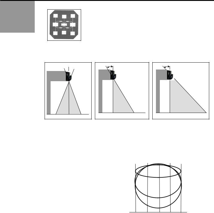
B.THE POSITION OF THE SENSING FIELD IS DETERMINED BY THE VERTICAL TILT ANGLE OF THE ANTENNA
A |
0º |
B |
20º |
C |
27º |
To obtain a sensing field as close to the door as possible : the tilt angle of the antenna must be set at the position (0°). - Example of use with a very deep operator.
To obtain a sensing field close to the door: the tilt angle of the antenna must be set at the position (20°) - Example of use with a normal operator. Shown in Picture B above.
To obtain a sensing field far from the door: the tilt angle of the antenna must be set at the maximum position (27°). - Example of use with a normal operator. Shown in picture C above.
SENSING FIELDS ACCORDING TO |
6.4’ |
3.2’ |
0 |
3.2’ |
6.4’ |
||
|
|
|
|
|
0 |
||
THE VERTICAL TILT ANGLE OF THE |
|
|
0º |
|
|
||
ANTENNA |
|
|
|
|
3.2’ |
||
The sensing fields on the right correspond |
|
|
|
|
|
||
|
|
|
|
|
|
||
to the following adjustments : |
|
|
|
|
|
|
|
|
|
20º |
|
|
6.4’ |
||
vertical angle of the |
|
|
|
|
|||
antenna : 0°, 20°, 27° ; |
|
|
|
|
|
|
|
|
|
|
|
|
|
||
sensitivity : 9 |
|
|
|
|
|
9.6’ |
|
Mounting height: 16’ |
|
|
|
|
|
|
|
|
|
|
|
|
|
|
12.8’ |
|
|
|
|
27 |
|
|
|
|
|
|
|
|
|
|
|
|
|
|
|
|
|
|
16’ |
75.1038 V3 Jun 2005 [Rev. June 10, 2005] |
Page 3 of 8 |
 Loading...