

Page 1
r
We open up New Horizons
DESCRIPTION
TECHNICAL
SPECIFICATIONS
DESCRIPTION OF
THE SENSOR
INSTALLATION
TIPS
The High Mounting Eagle Motion Detector (PN: 10EAGLE1HM) nd technology combined with digital processing to assure a
sharp, stable activation pattern with outstanding adjustability. Some of the adjustments include unidirectional sensing
capabilities, 3-dimensional angle adjustment, and heightened immunity to highly sensitive motion settings. These
adjustments can be made with BEA’s universal remote control. Other accessories available for the Eagle include the false
ceiling adapter (ECA), and the rain protection cover (ERA).
PRELIMINARY
Frequency: 24.125 GHz
Supply voltage:
Mounting height: 16.5 feet
Tilt angle:
Detection area: 13.1 ft x 8.2 ft
Minimum detection speed: 2in/sec. (measured in axis)
Power consumption: < 2 W
Standard output relay:
Max contact voltage
Max contact current
Max switching power
Hold time: 0.5 sec. to 9 sec. (adjustable)
Temperature range: -4°F to 131°F
Dimensions: 4.75in (W) x 3.15in (H) x 2.0in (D)
Weight: 0.5lbs
Material: ABS
Housing color: Black. Can be painted with non-metallic paint
Cable length: 30ft
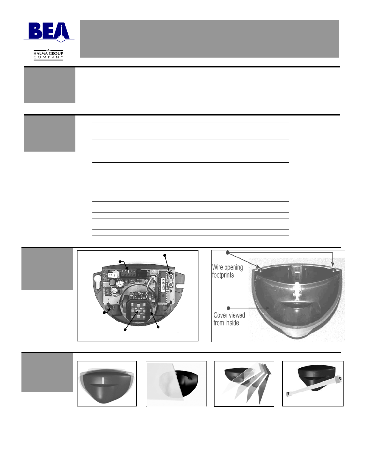
Terminal Block
Wire
Passage
Hole
Plana
Antenna
USERS GUIDE EAGLE HM
MOTION SENSOR
12 to 24 V AC : ± 10% :
12 to 24 V DC : -10% / +30% :
0° to 90° vertical
-30° to +30° lateral
60 VDC / 125 VAC
1 A (resistive)
30W (DC) / 60VA (AC)
Manual Set-up
Buttons
Lateral Adj.
For Antenna
75.1038 V2 Aug 2001 [Rev. June 10, 2005] Page 1 of 8
The sensor must be
firmly fastened in order
not to vibrate.
The sensor must not be
placed directly behind a
panel or any kind of
material.
The sensor must not
have any object likely to
move or vibrate in its
sensing field.
The sensor must not
have any fluorescent
lighting in its sensing
field.
Page 2
SAFETY
PRECAUTIONS
MECHANICAL
INSTALLATION -
OPENING THE
SENSOR
MECHANICAL
INSTALLATION -
PREPARATION
FOR MOUNTING
THE SENSOR
ELECTRICAL
INSTALLATION -
CABLING &
CONNECTION
75.1038 V3 Jun 2005 [Rev. June 10, 2005] Page 2 of 8
• Shut off all power going to the header before attempting any wiring procedures.
• Maintain a clean & safe environment when working in public areas.
• Constantly be aware of pedestrian traffic around the door area.
• Always stop pedestrian traffic through the doorway when performing tests that may result in unexpected
reactions by the door.
• Always check placement of all wiring and components before powering up to insure that moving door
parts will not catch any wires and cause damage to equipment.
• Ensure compliance with all applicable safety standards upon completion of installation
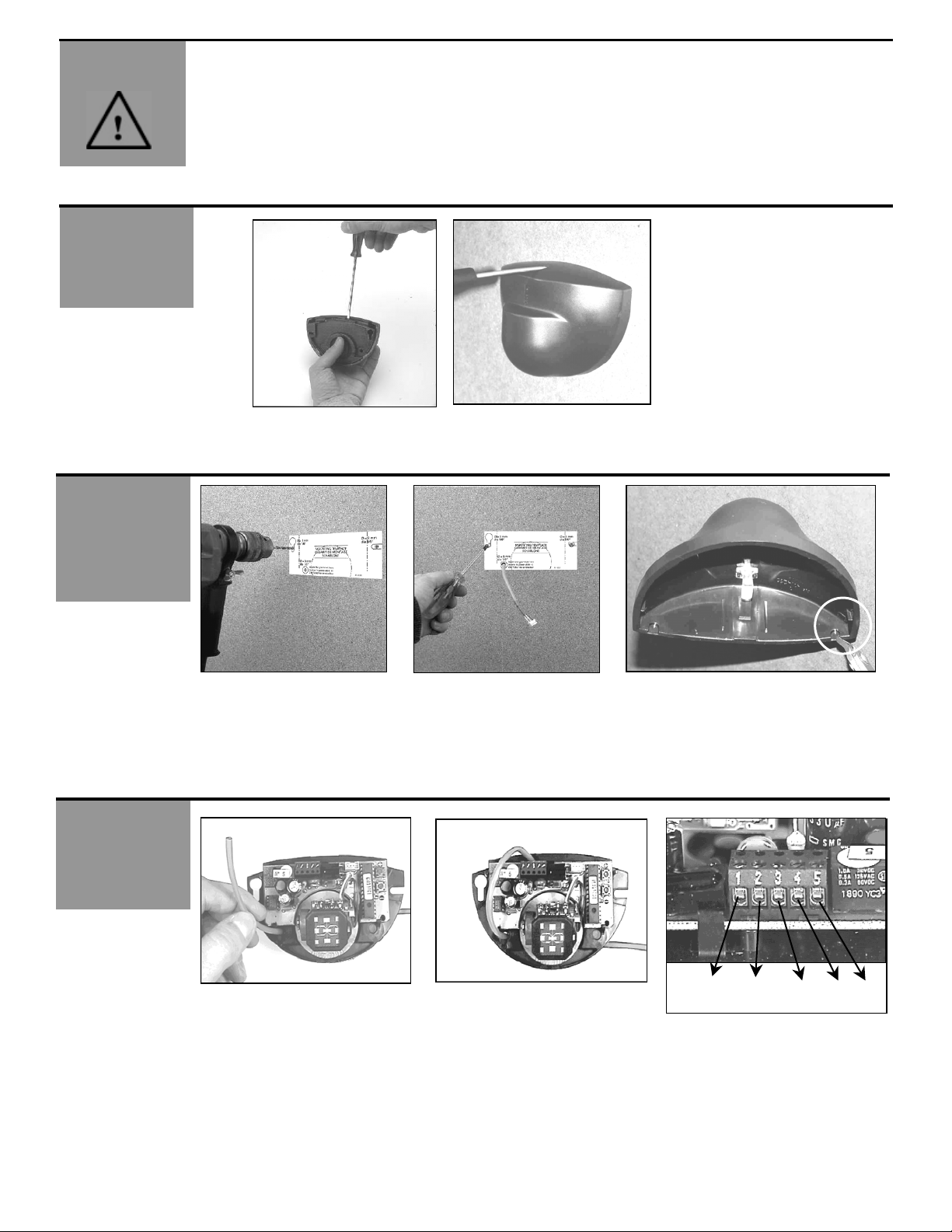
From behind, before installation From the front, after installation
Paste the template at
desired location.
Drill as instructed.
Run the cable through the wire
passage hole just below PCB.
Insert screws but do not screw
them fully in.
If possible, pass the cable
where it is supposed to go
through.
Position the sensor and tighten
the two screws. Make sure you
leave enough cable to reach the
terminal block.
If you don't want to drill your profile for
the cable, you can cut the wire opening
footprint as shown in the picture.
12-24 V AC/DC COM NO NC
Page 3
MECHANICAL
A
DJUSTMENTS -
SETTING THE
SENSING FIELD
DIMENSIONS
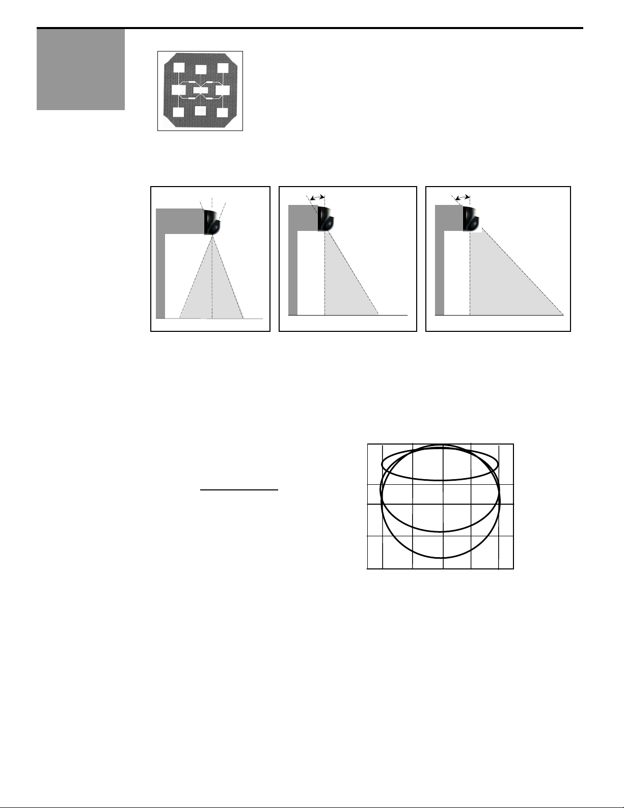
A. WIDTH OF THE SENSING FIELD
B. THE POSITION OF THE SENSING FIELD IS DETERMINED BY THE VERTICAL TILT ANGLE OF THE ANTENNA
The antenna for the Eagle HM is identified by it’s 9 elements. There is no narrow or wide
antenna. Only the 9 element antenna is utilized for the Eagle HM.
A
0º
To obtain a sensing field as close to the door as possible : the tilt angle of the antenna must be set at the position (0°).
- Example of use with a very deep operator.
To obtain a sensing field close to the door: the tilt angle of the antenna must be set at the position (20°)
- Example of use with a normal operator. Shown in Picture B above.
To obtain a sensing field far from the door: the tilt angle of the antenna must be set at the maximum position (27°).
- Example of use with a normal operator. Shown in picture C above.
75.1038 V3 Jun 2005 [Rev. June 10, 2005] Page 3 of 8
SENSING FIELDS ACCORDING TO
THE VERTICAL TILT ANGLE OF THE
ANTENNA
The sensing fields on the right correspond
to the following adjustments
vertical angle of the
antenna : 0°, 20°, 27° ;
sensitivity : 9
Mounting height: 16’
:
B
20º
6.4’ 3.2’ 0 3.2’ 6.4’
0º
20º
27
C
0
3.2’
6.4’
9.6’
12.8’
16’
27º
Page 4

A
MECHANICAL
DJUSTMENTS -
SETTING THE
SENSING FIELD
DIMENSIONS –
Cont.
For ceiling mounting, the vertical tilt angle
C. THE LATERAL POSITION OF THE SENSING FIELD IN FRONT OF THE DOOR IS DETERMINED BY THE LATERAL
D. THE DIMENSIONS (WIDTH, DEPTH_OF THE SENSING FIELD DEPEND ON THE SENSITIVITY SETTING.
75.1038 V3 Jun 2005 [Rev. June 10, 2005] Page 4 of 8
of the antenna must be set at the maximum
position of 70-75° and the spherical part of
the sensor must be oriented in the opposite
direction to the door.
TILT ANGLE OF THE ANTENNA.
70º
The sensing fields on the right
correspond to the
following adjustments
lateral angle of the
antenna : 15°, -15° ;
sensitivity : 6 (middle),
9 (max.)
Mounting height : 16’
+15º -15º
The sensing fields on the right correspond to the
following adjustments
vertical angle of the
antenna : 20°
Mounting height :16’
20° Angle
:
:
6.4’ 3.2’ 0 3.2’ 6.4’
S=6
S=9
6.4’ 3.2’ 0 3.2’ 6.4’
0
3.2’
6.4’
9.6’
0
3.2
6.4
9.6’
12.8’
16’
Page 5

BEA’s REMOTE
CONTROL
1. The Eagle SMR is fully compatible with BEA’s Remote Control as shown below. Use of the remote control should be
conducted within 10’ – 15’ of the sensor, and the remote should be pointed directly at the sensor when used. Refer to
the “Programming Guide” in the following section for each parameter and it’s values.
Number Keys
Not Used
Unlock
Check Values
Sensitivity
Relay Hold Time
Detection Mode
Immunity
Not Used
Plus +
Lock
Minus –
Not Used
Relay Configuration
Default Values
Not Used
PROGRAMMING
GUIDE
75.1038 V3 Jun 2005 [Rev. June 10, 2005] Page 5 of 8
1. The Eagle is SMR ready out of the box. The SMR (Self-Monitored Ready) function enables the sensor to
2. The Eagle SMR is equipped with a Motion Tracking Feature (MTF). The MTF is available when the Eagle is used in
* Every adjustment, when using the infrared remote control, must start with the unlocking function, and end
with the locking function.
communicate with BEA’s Door Control Unit (DCU), which allows for monitoring of the sensor, and interfacing with
the door control.
the uni-directional mode. The Eagle is factory preset with the MTF ON. MTF is recommended for use in short
vestibule areas to help reduce unwanted door hold-open time. Refer to the Programming Guide to alter this setting.
BEA recommends keeping the MTF enabled for all applications. The detection capabilities perform as follows:
BI-DIRECTIONAL MODE:
• Detection of all motion towards or away from the sensor.
UNI-DIRECTIONAL MODE:
• The detector will work in a uni-directional mode at all times regardless of traffic patterns - detecting only motion
moving toward the sensor.
OR
UNI-DIRECTIONAL MODE WITH MTF: The principle is as follows:
• The detector does NOT activate its relay as long as it detects movement exclusively moving away from the
detector. It acts like the classic unidirectional detector.
• As soon as the Eagle detects movement toward the sensor, it automatically switches to bi-directional mode.
• The Eagle maintains the bi-directional function for approximately 2 seconds following the last detection of motion
toward the door.
• At the end of the 2-second time frame, if the Eagle does not detect any further motion, it switches back to the
unidirectional mode.
Page 6

r
r
y
A
r
A
r
A
A
r
A
A
PROGRAMMING
GUIDE Cont.
UNLOCKING &
LOCKING
75.1038 V3 Jun 2005 [Rev. June 10, 2005] Page 6 of 8
KEY USER’S ACTIONS DEFAULT LED STATUS
UNLOCK
LOCK
CHECK VALUES
`
SENSITIVITY
RELAY HOLD TIME
RELAY
CONFIGURATION
Press the UNLOCK key once, then enter
your 4-digit code to unlock the Eagle.
0-9 0-9
When all parameters have been set, press
the LOCK key once. If you wish to enter a
new access code, use the 0-9 number keys
and enter the new 4-digit code within 10
seconds. The code must begin with the
number 1.
If you choose not to enter a new code,
press the LOCK key once more, and the
existing code will be retained.
= Locked with existing code.
0-9 0-9
= Locked with new code that is entered.
Press the function key that you desire to
inquire about, followed by pressing the
CHECK VALUES key.
fter pressing INQUIRY, count the numbe
of LED flashes – this corresponds to the
setting.
EXAMPLE:
7 = Default sensitivity
value
Sensitivity alters the sensitivity of the
motion field. Values range from 0 to 9,
minimum to maximum respectively.
0 = Minimum sensitivity
9 = Maximum sensitivity
Relay hold time refers to the hold time on
the output relay of the Eagle. Values range
from 0 to 9, .5 seconds to 9 seconds
respectively.
0-9 0-9
0-9 0-9
0 = .5 secs.
1 = 1 sec. to 9 = 9 seconds. 1
through 9 in 1 second increments.
The relay configuration has 4 possible
output values:
1 = Normally open relay
2 = Normally closed relay
3 = Continuous detection
4 = Continuous non-detection
0000
0000
7
0
1
The red LED will flash quickly afte
UNLOCK is pressed once. Afte
entering the valid code, Eagle will
flash red LED slowly.
If access code is set to the factor
default value of 0000, the Eagle will
automatically unlock after the
UNLOCK key is pressed once. The
red LED will immediately begin to
slowly flash red.
fter locking, the red LED stops
flashing and the sensor will no longe
be in a program mode.
fter pressing a function button, the
red LED flashes quickly. After pressing
the CHECK VALUES key, the LED
flashes the number of the current
setting. No LED flash will indicate a
setting of 0.
fter pressing the SENSITIVITY key,
the red LED flashes quickly. Afte
pressing a number button, the red LED
flashes slowly.
fter pressing the RELAY HOLD TIME
key, the red LED flashes quickly. After
pressing a number button, the red LED
flashes slowly.
fter pressing the RELAY
CONFIGURATION key, the red LED
flashes quickly. After pressing a
number button, the red LED flashes
slowly. (Normally Open relay indicates
relay closes upon detection, and is
open upon a power loss).
Page 7

A
A
A
PROGRAMMING
GUIDE Cont.
MANUAL SET-UP
TROUBLESHOOTING
75.1038 V3 Jun 2005 [Rev. June 10, 2005] Page 7 of 8
KEY USER’S ACTIONS DEFAULT LED STATUS
DETECTION MODE 3
IMMUNITY
DEFAULT VALUE
If a remote control is not available, you can adjust the sensitivity parameter ONLY, by means of the push
buttons + (Plus) and - (Minus).
The sensor parameters that are not accessible manually will remain at the factory preset values. Pressing the two push buttons,
located on the circuit board, simultaneously for at least two seconds, will restore all default values.
Detection mode offers 3 different levels of
detection: Bi-directional, Uni-directional and
Uni-directional with MTF (motion tracking
feature). MTF allows the Eagle to switch
from uni-directional to bi-directional upon
detection from the normal approach
direction.
Immunity alters the detection of unwanted
disturbances within the field of motion
detection
1 = Bi-directional
2 = Uni-directional
3 = Uni-directional with MTF
.
1 = Extreme sensitivity
2 = Normal Sensitivity
3 = Reduced sensitivity
1 = Restores default values for all
functions
2 = Boost Mode; Restores default
values for all functions, and increases
sensitivity for high-mount applications
fter pressing the DETECTION MODE
key, the red LED flashes quickly. After
pressing a number button, the red LED
flashes slowly.
2
fter pressing the IMMUNITY key, the
red LED flashes quickly. After pressing
a number button, the red LED flashes
slowly.
fter pressing the DEFAULT VALUE
key, the red LED flashes quickly. After
pressing a number button, the red LED
flashes slowly.
.
+ Press to increase
sensitivity by one unit
- Press to decrease sensitivity
by one unit.
The door will not open & LED does not
light up
The sensor does not respond to the
remote control
The sensor does not respond to the code
entered with the remote control
The door open and closes constantly 1. Increase the tilt angle of the antenna
1. Check supply voltage: 12 to 24 VAC: ± 10%
12 to 24 VDC: -10% / +30%
2. Check power connector
1. Check remote control battery insertion
2. Check remote control battery voltage
1. Remove the cover and press the 2 buttons
simultaneously for at least two seconds. This will reset
the lock code to 0000. Then press the unlock button to
enable you to access the settings with the remote control.
2. Reduce sensitivity
Page 8

A
OTHER
CCESSORIES
COMPANY
CONTACT
PN: 10ECA
For mounting into the ceiling, use
the ECA embedding accessory.
If after troubleshooting a problem, a satisfactory solution cannot be achieved, please call B.E.A., Inc.
for further assistance during Eastern Standard Time at 1-800-523-2462 from 8am - 5pm.
For after-hours, call East Coast: 1-866-836-1863 or 1-800-407-4545 / Mid-West: 1-888-308-8843 /
West Coast: 1-888-419-2564. DO NOT leave any problem unresolved. If you must wait for the following workday to
call B.E.A., leave the door inoperable until satisfactory repairs can be made.
NEVER sacrifice the safe operation of the automatic door or gate for an incomplete solution.
Web: www.beasensors.com
PN: 10EMB
Bracket for mounting on the
top of the door header.
PN: 10ERA
Rain protection accessory.
75.1038 V3 Jun 2005 [Rev. June 10, 2005] Page 8 of 8
 Loading...