

Page 1
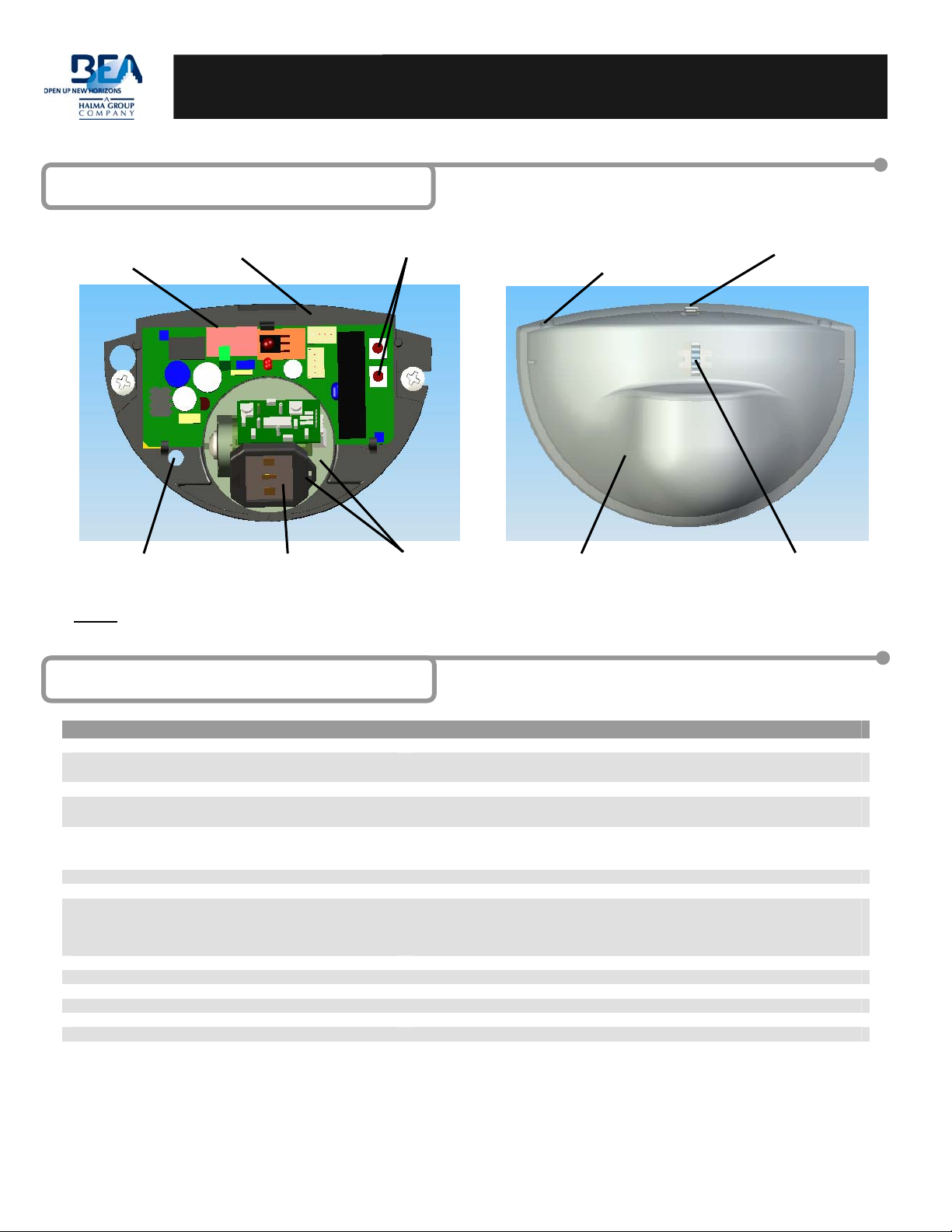
1 Description
Terminal
Block
Narrow Antenna Storage Manual Set-Up Buttons
EAGLE
USER GUIDE
Wire Opening Knockout
(inside the cover)
Opening Tab
Wire Passage Hole Planar Antenna
NOTE: For mounting heights between 10’ and 16’, use BEA model 10EAGLEHM (high mount).
Lateral and Angle
Adj. For Antenna
Front Cover
2 Technical Specifications
DESCRIPTION SPECIFICATION
Frequency: 24.125 GHz
Supply voltage:
Mounting height: Normal: 7’; Maximum: 10’-0”
Tilt angle:
Detection area:
Wide
Narrow
Minimum detection speed: 2 in/sec. (measured in axis)
Power consumption: < 2 W
Standard output relay:
Max contact voltage
Max contact current
Max switching power
Hold time: 0.5 sec. to 9 sec. (adjustable)
Temperature range: -4°F to 131°F
Dimensions: 4.75in (W) x 3.15in (H) x 2.0in (D)
Weight: 0.5lbs
Material: ABS
Housing color: Black. Can be painted with non-metallic paint
Cable length: 6ft
12 to 24 V AC: ± 10%:
12 to 24 V DC: -10% / +30%:
0° to 90° vertical
-15° to +15° lateral
13ft (W) x 6.5ft (D)
6.5ft (W) x 8.2ft (D) (supplied as optional)
60 VDC / 125 VAC
1 A (resistive)
30W (DC) / 60VA (AC)
LED
75.5185.04 20070727 Page 1 of 8
Page 2
3 Installation
Tips
1
The sensor must be firmly
fastened to prevent
vibration.
Safety Precautions
2
• Shut off all power going to the header before attempting any wiring procedures.
• Maintain a clean & safe environment when working in public areas.
• Constantly be aware of pedestrian traffic around the door area.
• Always stop pedestrian traffic through the doorway when performing tests that may result in unexpected reactions by
the door.
• Always check placement of all wiring and components before powering up to insure that moving door parts will not
catch any wires and cause damage to equipment.
The sensor must not be
placed directly behind a
panel or any kind of
material.
The sensor must not have
any object likely to move
or vibrate in its sensing
field.
The sensor must not have
any fluorescent lighting in
its sensing field.
• Ensure compliance with all applicable safety standards upon completion of installation.
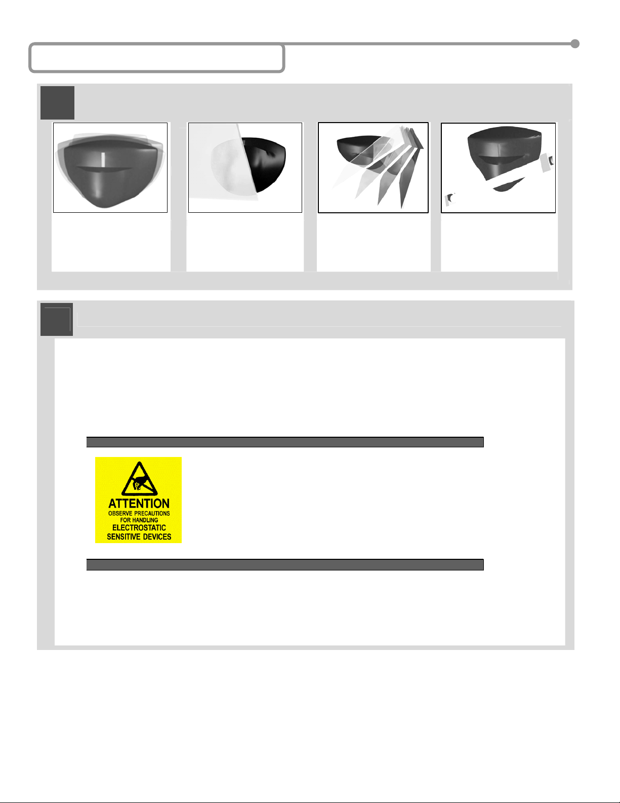
ELECTROSTATIC DISCHARGE (ESD) PRECAUTIONS
Circuit board components are vulnerable to damage by electrostatic discharge
(ESD). ESD can cause immediate or subtle damage t o sensitive electronic parts.
An electrostatic charge can build up on the hum an body and t hen discharge when
you touch a board. A discharge can be produced when walking across a carpet
and touching a board, for example. Before handling any board, make sure you
dissipate your body’s charge.
CAUTION
75.5185.04 20070727 Page 2 of 8
: In the event a unit needs to be opened, observe the following precautions.
Ground yourself by touching a conduct ive s urface of the door or other el em ent connec ted to c ommon earth
ground to discharge the static electricity present in your body.
Avoid walking around while replacing items inside the case, especially if you are on carpet or during
conditions of low temperature and low humidity.
Handle the board by the edges only to avoid touching electronic components.
Store a loose board in an anti-static bag.
Page 3
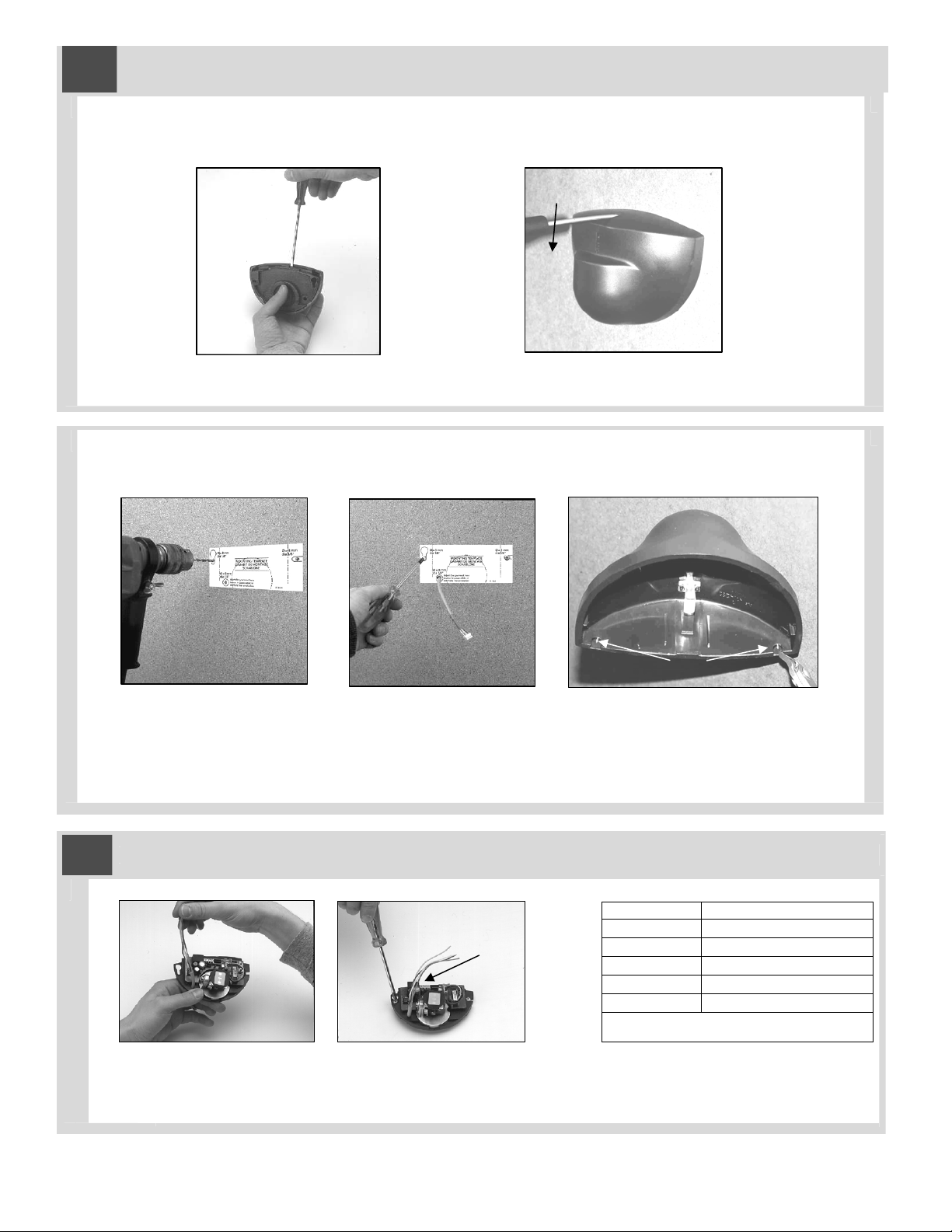
Mechanical Installation
3
Opening the sensor
From behind, before installation From the front, after installation
Mounting the sensor
or
Paste the template at desired
location.
Drill as instructed. Pass the cable where
4
Electrical Installation
Run the cable through the wire
passage hole just below PCB.
Insert screws but do not screw
them fully in.
indicated.
Position the sensor and tighten the
two screws. Make sure you leave
enough cable to reach the terminal
block near the top of the sensor.
Optional cable routing:
Notch the cover as shown in
the picture.
Terminal Connection
1 (Red) 12 to 24 VAC / DC (+)
2 (Black) 12 to 24 VAC / DC (-)
3 (White) Relay Common
4 (Green) Relay N.O.
5 Relay N.C.
Note: Input power tolerance is +/- 10% for
AC, and -10% to +30% for DC power.
Wiring connections are as shown above.
75.5185.04 20070727 Page 3 of 8
Page 4

Mechanical Adjustments
5
A. THE WIDTH OF THE SENSING FIELD IS DETERMINED BY THE CHOICE OF THE PLANAR ANTENNA (OPTION)
Wide sensing field:
3-element antenna
Carefully remove the
protective cover of the antenna
with a screwdriver.
Narrow sensing field:
6-element antenna
Change the antenna and
replace the protective cover.
6.4’ 3.2’
3-Element
Antenna
SENSING FIELDS ACCORDING TO THE TYPE
OF ANTENNA
The sensing fields above correspond to the
following adjustments:
vertical angle of the antenna: 30°
sensitivity: 9
Mounting height: 7’
0
3.2’ 6.4’
6-Element
Antenna
0
3.2’
6.4’
9.6’
B. THE POSITION OF THE SENSING FIELD IS DETERMINED BY THE VERTICAL TILT ANGLE OF THE ANTENNA
A
0º
Sensing field as close to the door
as possible:
-antenna set at the position of 0°
SENSING FIELDS ACCORDING TO THE
VERTICAL TILT ANGLE OF THE ANTENNA
The sensing fields on the right correspond
to the following adjustments:
wide sensing field antenna
vertical angle of the antenna: 0°, 20°, 45°
sensitivity: 9
Mounting height: 7’
Sensing field close to the door:
-antenna set at the position of 30°
B
º
Sensing field far from the door:
-antenna set at the position of 45°
75.5185.04 20070727 Page 4 of 8
6.4’
3.2’
C
º
0
º
º
3.2’
6.4’
º
9.6’
3.2’
0
6.4’
Page 5

º
TILT ANGLE OF THE ANTENNA.
For ceiling mounting, the vertical tilt angle of
the antenna must be set at the maximum
position of 70-75° and the spherical part of
the sensor must be oriented in the opposite
direction to the door.
C. THE LATERAL POSITION OF THE SENSING FIELD IN FRONT OF THE DOOR IS DETERMINED BY THE LATERAL
-
D. THE DIMENSIONS (WIDTH, DEPTH) OF THE SENSING FIELD DEPEND ON THE SENSITIVITY SETTING.
The sensing fields on the right correspond to the
following adjustments:
Wide sensing field antenna
Vertical angle of the
antenna: 30°
Mounting height: 7’
E. THE DIMENSIONS (WIDTH, DEPTH) OF THE SENSING FIELD DEPEND ON THE MOUNTING HEIGHT
The sensing fields on the right correspond to the
following adjustments:
Wide sensing field antenna
Vertical angle of the
antenna: 20°
Sensitivity: 9
Mounting height: 9.6’
+
º
The sensing fields on the right correspond
to following adjustments:
Wide sensing field antenna
Lateral angle of the
antenna: +30°, -30°
Sensitivity:
Mounting height: 7’
1= min., 6 = middle, 9 = max.
SENSING FIELDS – CEILING MOUNT
The sensing fields above correspond to
the following adjustments:
Vertical angle of antenna: 70º
Sensitivity: 9
Mounting height: 7’
-30º
6.4’
6.4’
6.4’
3.2’
6.4’
3.2’
3.2’ 0
0
3.2’
0
0
3
6
8
9
3.2’
3.2’
0
3.2’
3.2’ 6.4’
6.4’
6.4’
3-Element
Antenna
6-Element
Antenna
6.4’
0
3.2’
+30º
0
3.2’
6.4’
9.6’
0
3.2’
6.4’
9.6’
75.5185.04 20070727 Page 5 of 8
Page 6

Programming Guide
6
The Eagle is equipped with a Motion Tracking Feature (MTF). The MTF is available when the Ea gle is used in the unidirectional mode. The Eagle is factory preset with the MTF ON. MTF is recommended for use in short vestibule areas to
help reduce unwanted door hold-open time. Refer to the Programming Guide to alter this setting. BEA recommends
keeping the MTF enabled for all applications. The detection capabilities perform as follows:
BI-DIRECTIONAL MODE:
• Detection of all motion towards or away from the sensor.
UNI-DIRECTIONAL MODE:
• The detector will work in a uni-directional mode at all times regardless of traffic patterns - detecting only motion moving
toward the sensor.
OR
UNI-DIRECTIONAL MODE WITH MTF: The principle is as follows:
• The detector does NOT activate its relay as long as it detects movement exclusively moving away from the detector. It
acts like the classic unidirectional detector.
• As soon as the Eagle detects movement toward the sensor, it automatically switches to bi-directional mode.
• The Eagle maintains the bi-directional function for approximately 2 seconds following the last detection of motion toward
the door.
• At the end of the 2-second time frame, if the Eagle does not detect any further motion, it switches back to the
unidirectional mode.
Number Keys
Number keys (0 through 9) are used for
assigning a value for a given function
Adjustment Keys
Plus (+) and minus (-) keys are used for
incremental adjustments to the sensor
Unlock
Inquire
Lock
?
To UNLOCK the sensor:
Press the UNLOCK key once. Red LED
flashes quickly
To LOCK the sensor:
Press the LOCK key twice, OR press
once then followed by a 4-digit lock
code. If less than 4 digits, press
lock again after the last digit. LED
goes out when complete.
To INQUIRE the sensor:
Unlock the sensor, press the desired
function key, followed by the
INQUIRY key – the number of
green flashes corresponds to the
value.
Default: 0000
Relay Configuration
The relay configuration has 4 possible
output values:
1= Normally Open Relay
2= Normally Closed Relay
3=Continuous Detection
4=Continuous Non-Detection
Default: 1
Default Values
After pressing the DEFAULT VALUE key,
the red LED flashes quickly. After
pressing a number button, the red LED
flashes slowly.
1 = Normal Mounting Height (only for
serial numbers lower than 84000)
2 = Boost Mode, increases sensitivity for
high mount applications.
9 = Restore default values except lock
code (for serial number 84000 and
greater)
75.5185.04 20070727 Page 6 of 8
Page 7

Sensitivity
0 = Minimum Sensitivity
9 = Maximum Sensitivity
Default: 8
Detection Mode
Detection mode offers 3 different levels of
detection:
1 = Bi-Directional
2 = Uni-Directional
3 = Uni-Directional with motion tracking feature
Default: 3
Relay Hold Time
Relay hold time refers to the hold time on the
output relay of the Eagle. Values range from 0 to
9.
0 = .5 sec.
1 = 1 sec through 9 = 9 sec in 1 second intervals
Default: 0
Immunity helps to reduce the chance of
unwanted detections due to environmental
disturbances.
1 = Reduced
2 = Normal
3 = Increased
4 through 9: enhanced immunity (for highly
reflective environment)
Default: 2
Immunity
* Every adjustment, when using the infrared remote control, must start with the unlocking function, and end with the
locking function.
Manual Setup
7
If a remote control is not available, only the sensitivity parameter can be adjusted manually, by means of the push
buttons + (Plus) and - (Minus).
The sensor parameters that are not accessible manually will remain at the factory preset values.
+ Press to increase
sensitivity by one unit.
- Press to decrease
sensitivity by one unit.
Pressing the two push buttons located on the circuit board, simultaneously for at least two seconds, will
restore all default values except the lock code. Previously set lock codes will be retained.
75.5185.04 20070727 Page 7 of 8
Page 8

4 Troubleshooting
SYMPTOMS PROBABLE CAUSE CORRECTIVE ACTION
The door will not open and no red
LED lights up.
The door opens and closes
constantly.
When closing the door creates vibrations picked
The door will not close the.
Red LED off.
It rains and the sensor detects for no
apparent reason.
In airlock vestibules, the sensor sees the
opposite door.
The sensor power is off. Check the wiring and power supply.
The door control is set to level 3. Set door control to automatic mode (level 1).
The sensor “sees” the door moving Increase the tilt angle and/or reduce the sensitivity
and/or increase the immunity.
Ensure the sensor is correctly fixed.
up by the sensor.
Switch to unidirectional mode.
Increase the immunity.
Reduce the sensitivity.
On Off switch at door control in wrong position or is
faulty.
Improper output configuration on the sensor.
Check to insure On-Off switch for door is in the ON or
AUTOMATIC position.
Check the output configuration setting on each sensor
connected to the door operator.
The sensor detects the motion of the raindrops.
Use the ERA accessory.
Switch to unidirectional mode (without MTF) and increase
the immunity.
Increase immunity.
In airlock vestibules, the sensor sees the
Make sure the antenna for the narrow sensing field is used.
movement of the door leaves, despite of
an increased immunity.
In metallic environments, the sensor
Increase immunity.
detects objects outside its detection
field.
The sensor will not unlock when access
code is entered.
Batteries in the remote control are weak or installed
improperly.
Remote control improperly pointed.
5 Accessories (sold individually)
PN: 10ECA
For mounting into the ceiling, use the
ECA embedding accessory.
PN: 10EMB
Bracket for mounting on the top of the
door header.
Check the batteries insertion.
Change the batteries.
Point the remote control toward the sensor.
PN: 10ERA
Rain protection accessory.
6 Company Contact
The following numbers can be called 24 hours a day, 7 days a week. For more information, visit www.beasensors.com.
75.5185.04 20070727 Page 8 of 8
Do not leave problems unresolved. If a satisfactory solution cannot be achieved after troubleshooting a
problem, please call BEA, Inc. If you must wait for the following workday to call BEA, leave the door
inoperable until satisfactory repairs can be made. Never sacrifice the safe operation of the automatic door
or gate for an incomplete solution.
West: 1-888-419-2564 Mid-West: 1-888-308-8843
South-East: 1-800-407-4545 North-East: 1-866-836-1863
US and Canada: 1-866-249-7937 Canada: 1-866-836-1863
 Loading...