

Page 1

COMBO-PLATE
USER’S GUIDE
COMBINATION KEYSWITCH AND PUSH PLATE SWITCH
1 Description
The BEA Combo-Plate is two switches in one. The keyswitch and push plate switch can be set up to work
independently of each other or the keyswitch can turn off/on the push plate switch, thus, providing an economical way
to secure the activation of an automatic door after hours. Both the keyswitch and push plate switch share a 4 1/2”
square back plate, making it easy to install in any standard 2-gang electrical box. NOTE: The mortise cylinder is not
included with this product.
2 Specications
DESCRIPTION SPECIFICATION
Key Switch Single Pull Single Throw / Maintained (10COMBOPLATE) or Momentary Contact (10COMBOPLATEMOM):
Push Plate Cherry Switch: Single Pull Single Throw / Momentary Contact: 15A @ 125V AC
Dimensions 4 1/2” X 4 1/2”
3 Precautions
6A @ 125 VAC or 3A @ 250 VAC
Shut off all power going to header before attempting any wiring procedures.
Maintain a clean and safe environment when working in public areas.
Constantly be aware of pedestrian trafc around the door area.
Always stop pedestrian trafc through the doorway when performing tests that may result in unexpected reactions by the
door.
ESD electrostatic discharge: Circuit boards are vulnerable to damage by electrostatic discharge. Before handling any board
ensure you dissipate your body’s charge.
Always check placement of all wiring before powering up to insure that moving door parts will not catch any wires and cause
damage to equipment.
Ensure compliance with all applicable safety standards (i.e. ANSI A156.10) upon completion of installation.
DO NOT attempt any internal repair of the sensor. All repairs and/or component replacements must be performed by BEA,
Inc. Unauthorized disassembly or repair:
1. May jeopardize personal safety and may expose one to the risk of electrical shock.
2. May adversely affect the safe and reliable performance of the product will result in a voided product warranty.
4 Pre Installation Check
1. When preparing to wire multiple devices together for a ‘system’ conguration, it is best to ensure the correct operation of each device
independently before starting to help reduce troubleshooting time later in the event of a discrepancy.
2. Prior to installing any equipment, ensure the correct line voltage and stability. When applying equipment on a new installation utilizing new
electrical supply circuits, always ensure that correct line voltage exists and is stable. Remember to shut the power back off after this is
checked and before performing any wiring to the system.
5 Installation
To install the BEA Combo-Plate perform the following:
1. Install the 2-gang electrical box (purchased separately) in its intended location.
2. Assemble the keyswitch portion of the assembly with a mortise cylinder (purchased separately) (Figure 1).
NOTE: BEA recommends that a 1-1/8” length mortise cylinder be used in this assembly. However, a 1-1/4” length mortise cylinder will also
work. Select the appropriate cam depending on the switch conguration (Figure 2).
3. Wire the device for its intended use. The keyswitch can be wired to toggle the push plate switch “on/off” (Figure 3) or the two switches can
be wired for independent use.
75.5645.02 20140103 Page 1 of 2
Page 2
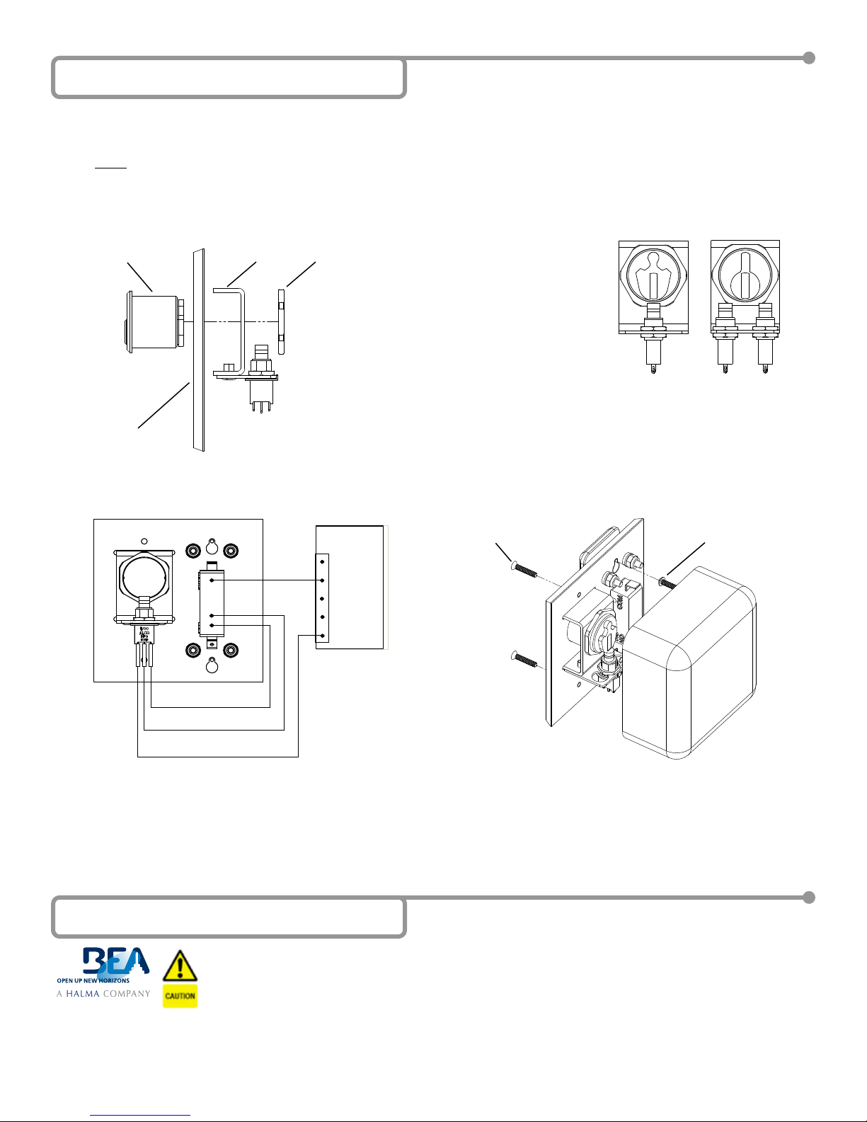
5 Installation (Continued)
4. Partially insert the two socket cap screws into the upper left and lower left mounting holes of the wall box. Slide the key holes of the ComboPlate over the screws and tighten by inserting a hex wrench into the through holes of the push plate. Fasten the right side of the Combo-
Plate using two at head screws (Figure 4).
NOTE: The installer may choose between two styles of at head screws: Phillips head screws or tamper-resistant spanner screws (both
provided in the hardware kit).
Mortise
Cylinder
Wall
Plate
Figure 1
COM
N.O.
N.C.
Bracket
Figure 3
Switch
Cylinder
Lock
DOOR
CONTROL
STALL COM
COM
STALL
SAFETY
ACTIVATION
Select shape of cam shown for
number of switches used (specify
when ordering cylinder).
Adjust height of switch on
bracket until cam triggers
positively when rotated.
(2) 6-32
Flat Head Screws
Corbin Russwin®
#ML2200,
®
Schlage
#B520-233
or Equivalent
Figure 4
Figure 2
Schlage® #B520-256,
Yale® #2160,
Arrow® #004,
Sargent® #13-0660
or Equivalent
(2) 6-32
Socket Cap Screws
RED N.C.
WHITE COM.
YELLOW N.O.
Example Wiring
6 Company Contact
Do not leave problems unresolved. If a satisfactory solution cannot be achieved after troubleshooting a problem, please
call BEA, Inc. If you must wait for the following workday to call BEA, leave the door inoperable until satisfactory repairs
can be made. Never sacrice the safe operation of the automatic door or gate for an incomplete solution.
The following numbers can be called 24 hours a day, 7 days a week. For more information, visit www.beasensors.com.
Canada and Texas:
Page 2 of 2 75.5645.02 20140103
East:
1-866-249-7937
1-866-836-1863
Central:
West:
1-800-407-4545
1-888-419-2564
 Loading...