


Bazooka EL604/608, EL804/808, EL104/108, EL6A-hp, EL10A-hp Owners Manual
...MODELS INCLUDED IN THIS MANUAL:
EL604/608, EL804/808, EL104/108, EL6A-hp, EL8A-hp, EL10A-hp,
RS604DV/608DV, RS804DV/808DV, RS104DV/108DV, RS6A-hp,
RS8A-hp, RS10A-hp, SM804, SM104, SM8A, SM10A, SM8A-hp,
SM10A-hp, CS8A5
.INC SERVICES, AUDIO SOUTHERN .BLVD FLORIDA 15049 70819 LA ROUGE, BATON
PLACE STAMP HERE

Dear Friend,
Thank you for selecting Bazooka® subwoofer speaker systems for your car stereo system. Today, the Bazooka represents Bazooka Mobile Audio’s continued commitment to efficiency and design. An innovative manufacturing process developed by SAS for the Bazooka provides consumers with state-of-the-art speaker system design.
At SAS, we take pride in manufacturing the most revolutionary bass speaker systems ever created, featuring our patented Bass Tubes® enclosure design, and we hope you will take pride in owning them.
Several years ago, we realized that efficiency was the wave of the future in Autosound, so we made a commitment to design, manufacture, and deliver the most efficient speaker systems possible.
Today we market our patented speaker systems worldwide and the high quality of the Bazooka brand is well respected by consumers and dealers of all nationalities.
When properly installed, Bazooka subwoofer speaker systems will give you years of clean uninterrupted sound reproduction. Therefore, I urge you to take a few minutes of your time to review this instruction booklet. It was designed to give you a better understanding of our products and to explain how to apply them properly.
Thank you again for choosing Bazookas. Our early commitment to quality has made them the product of choice, and I am sure you will agree that you have made the right one! Enjoy!
Sincerely,
JON C. JORDAN
President
SAS/BAZOOKA
CONTENTS |
|
HELPFUL HINTS BEFORE YOU BEGIN |
PG 2 |
VEHICLE PLACEMENT RECOMMENDATIONS |
PG 3 |
BOAT PLACEMENT RECOMMENDATIONS |
PG 4 |
MOUNTING THE BAZOOKA |
PG 5-7 |
WIRING DIAGRAMS |
PG 8-10 |
SPECIFICATIONS |
PG 11-12 |
FEATURES |
PG 13-14 |
WIRING |
PG 15-21 |
TROUBLESHOOTING |
PG 22-23 |
WARRANTY |
PG 24-26 |
HELPFUL HINTS—BEFORE YOU BEGIN
Please take time to read through this manual and plan out your installation before you begin!
Locate an area in the rear of the vehicle where you would like to place the Bazooka speaker systems. The location you have selected must meet the following requirements in order for the Bazooka to be properly installed in the vehicle:
1)The woofer (grill end) should be facing into a corner. (See vehicle placement recommendations on pg. 3)
2)Ideally, there should be 2 to 4 inches between the woofer and the corner it is pointing into.
3)The mounting area should be carefully checked to be sure that the mounting screws will not damage the gas tank,
electrical wiring, fuel lines, or the spare tire during the mounting of the strap bases.
4)The strap mounting bases should be screwed securely to a rigid surface that is part of, or anchored to, the structure of the vehicle.
1 |
2 |

VEHICLE PLACEMENT RECOMMENDATIONS |
BOAT PLACEMENT RECOMMENDATIONS |
TRUCK INSTALLATION
tube size is exaggerated for emphasis
HATCHBACK INSTALLATION
tube size is exaggerated for emphasis
BOW RIDER/SKI BOAT
tube size is exaggerated for emphasis
• Under passenger console
• Under seat storage compartment
SEDAN INSTALLATION
tube size is exaggerated for emphasis
SPORT YACHT
tube size is exaggerated for emphasis
• Under bed storage compartment
• Under seat storage compartment
3 |
4 |
MOUNTING THE BAZOOKA
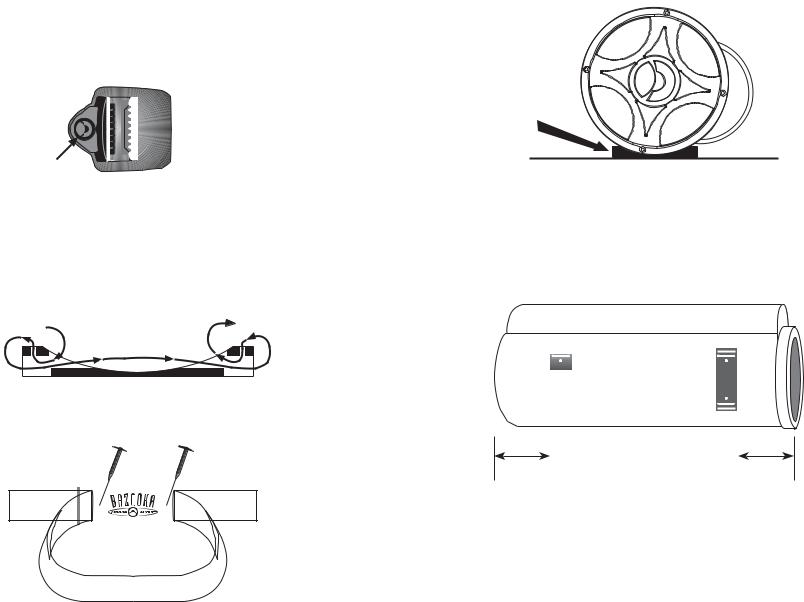
Figure 1
Top
Logo should face up
1. With the topside of the buckle facing up (see figure 1), lace the strap through the mounting base as illustrated in figure 2
Figure 2
Figure 3
2. After the strap is completely laced through the mounting base, make a loop with the strap, where it runs across the middle of the base as illustrated in figure 3. This loop is necessary to access the two mounting holes in the base.
Figure 4
3. Place each mounting base under the Bass Tubes® enclosure so that the apex at the bottom of the tube sits inside the mounting base as in figure 4.
,, |
|
|
|
|
|
,, |
|
|
|
|
|
||
|
|
|
|
|
||
|
|
|
|
|
||
|
|
|
|
|
||
|
|
Figure 5 |
|
|
||
|
|
|
|
|||
|
|
|
|
|||
3 |
|
|
|
|
3 |
|
4.Move the bases so that they are spaced approximately 3” from each end of the enclosure as illustrated in figure 5.
5.Remove the Bass Tubes® enclosure without moving the mounting bases and set it aside.
6.Screw each mounting base securely in place with screws provided as illustrated in figure 3.
5 |
6 |
See Model Size |
|
EL WIRING DIAGRAM |
|||||||
|
|
|
For Length |
|
|
|
|
||
|
|
|
|
|
|||||
|
|
|
|
|
|
|
|
|
|
|
|
|
|
|
|
|
|
|
|
|
|
|
|
|
|
|
|
|
|
|
|
|
|
|
|
|
|
|
|
|
|
|
|
|
|
|
|
|
|
|
|
|
|
|
|
|
|
|
|
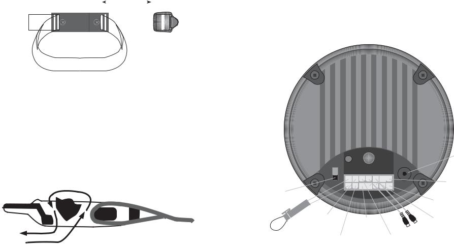
Figure 6
7.Remove any slack in the strap by feeding it out of the mounting base on the loose end of the strap opposite the buckle.
8.Place the Bass Tubes® enclosure on the mounting bases and fasten the buckles as illustrated in figure 7. The strap should loop through the buckle and be tightened securely by holding the strap in place with one hand and pulling the loose end away from the buckle, but against the cabinet.
Model |
Length |
6” |
17” |
8” |
22” |
10” |
27” |
Figure 7
Technical Note:
Due to the jarring and shifting that can occur in a vehicle, the mounting straps may stretch or loosen. We recommend that you check the straps regularly to assure that your Bass Tubes® enclosure is mounted securely in place.
|
|
LEVEL |
|
OPTIONAL |
|
|
|
|
REMOTE |
|
|
|
|
LEVEL |
|
|
|
|
CONTROL |
INPUT |
|
|
|
16 GAUGE |
|
|
|
BLACK CHASSIS |
|
PHASE |
|
|
|
GROUND |
SWITCH |
|
|
|
16 GAUGE RED |
|
|
|
|
|
|
|
|
|
BATTERY (12v+) |
|
GRAY |
|
|
ORANGE |
|
HI-LEV |
|
|
|
|
GN/TRACE |
|
REMOTE |
|
|
INPUT (+) |
|
||
|
HI-LEV |
|
RCA |
|
|
|
|
||
|
|
INPUT (-) |
|
PHONO PLUGS |
QUICK DISCONNECT |
GRAY/TRACE |
|
GREEN |
Right & Left Low |
|
Level Inputs |
|||
YELLOW ON/OFF |
|
|||
HI-LEV |
|
HI-LEV |
|
|
JUMPER LOOP |
|
|
||
INPUT (-) |
|
INPUT (+) |
|
|
|
|
|
NOTE:
REMOVE AUTO TURN-ON LOOP TO USE ORANGEREMOTE WIRE FOR NORMAL REMOTE TURN-ON
7 |
8 |
 Loading...