

Page 1
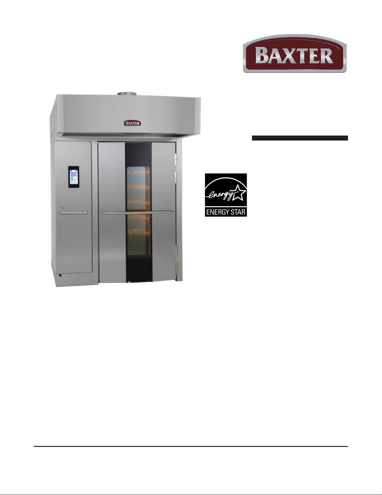
Operator
Manual
ML-132577 OV520G1
ML-132576 OV520G2
ML-132578 OV520E2
ML-132579 OV520E1
OV520 ROTATING RACK OVEN WITH
SMART TOUCH
Model Number: ___________
Serial Number: ___________
Date of Installation: ___________
Baxter Mfg, a Division of ITW FEG, LLC • 19220 State Route 162 East • Orting, WA 98360-9236
Phone: (360) 893-5554 • Fax: (360) 893-1337
www.baxtermfg.com
TM
CONTROL
FORM 36764 Rev. D (September 2022)
Page 2
IMPORTANT FOR YOUR SAFETY
POST IN A PROMINENT LOCATION THE INSTRUCTIONS TO BE FOLLOWED IN THE EVENT
THE SMELL OF GAS IS DETECTED. THIS INFORMATION CAN BE OBTAINED FROM THE
LOCAL GAS SUPPLIER.
IMPORTANT
IN THE EVENT A GAS ODOR IS DETECTED, SHUT DOWN UNITS
AT MAIN SHUTOFF VALVE AND CONTACT THE LOCAL GAS
COMPANY OR GAS SUPPLIER FOR SERVICE.
FOR YOUR SAFETY
DO NOT STORE OR USE GASOLINE OR OTHER FLAMMABLE
VAPORS OR LIQUIDS IN THE VICINITY OF THIS OR ANY OTHER
APPLIANCE.
IMPROPER INSTALLATION, ADJUSTMENT,
ALTERATION, SERVICE OR MAINTENANCE CAN CAUSE
PROPERTY DAMAGE, INJURY OR DEATH. READ THE
INSTALLATION, OPERATING AND MAINTENANCE
INSTRUCTIONS THOROUGHLY BEFORE INSTALLING OR
SERVICING THIS EQUIPMENT.
IN THE EVENT OF A POWER FAILURE, DO NOT ATTEMPT TO
OPERATE THIS DEVICE.
KEEP AREA AROUND OVEN CLEAR OF COMBUSTIBLES. DO
NOT OBSTRUCT COMBUSTION AND VENTILATION OPENINGS
ON THE OVEN.
DO NOT SPRAY AEROSOLS IN THE VICINITY OF THIS APPLIANCE
WHILE IT IS IN OPERATION.
© BAXTER MFG., 2022
– 2 –
Page 3

TABLE OF CONTENTS
GENERAL ................................................................................................................................................ 5
INSTALLATION ....................................................................................................................................... 5
Warranty ............................................................................................................................................. 5
OPERATION ........................................................................................................................................... 5
Basic Operation ............................................................................................................................... 5
Rack Loading ................................................................................................................................... 6
Rack Unloading ............................................................................................................................... 6
Operating Modes ................................................................................................................................ 7
Auto Mode ...................................................................................................................................... 7
Manual Mode ................................................................................................................................. 7
Smart™ Touch Toolbox ................................................................................................................. 7
Display Screen Buttons ...................................................................................................................... 8
Auto Mode Buttons ......................................................................................................................... 8
Manual Mode Buttons .................................................................................................................... 9
Classic Manual Mode Display and Buttons .................................................................................. 10
Toolbox Buttons .............................................................................................................................11
Miscellaneous Screens .................................................................................................................11
Using Auto Mode .............................................................................................................................. 12
Creating a Recipe ........................................................................................................................ 12
Using a Recipe ............................................................................................................................. 17
Viewing a Recipe in Progress ...................................................................................................... 17
Manual Mode .................................................................................................................................... 18
Using Manual Mode ..................................................................................................................... 18
Using Classic Manual Mode ......................................................................................................... 20
Using Smart Touch Toolbox Mode .................................................................................................... 20
User Manual Screen .................................................................................................................... 20
Data Exchange Screen ................................................................................................................ 21
Client Parameters Screen ............................................................................................................ 21
Parameters Table ......................................................................................................................... 22
Auto O ........................................................................................................................................ 23
Shutdown .......................................................................................................................................... 24
Restarting Oven ................................................................................................................................ 24
TROUBLESHOOTING ......................................................................................................................... 25
Burners Will Not Light on Gas Oven ................................................................................................. 25
Other Troubleshooting Topics ........................................................................................................... 25
Error Screen Information .................................................................................................................. 25
CLEANING ............................................................................................................................................ 27
– 3 –
Page 4

MAINTENANCE .................................................................................................................................... 28
General ............................................................................................................................................ 28
As Needed ................................................................................................................................... 28
Daily ............................................................................................................................................. 28
Weekly ........................................................................................................................................ 28
Monthly ......................................................................................................................................... 28
Bi-Monthly .................................................................................................................................... 28
Annually ....................................................................................................................................... 28
Preventive Maintenance ................................................................................................................... 28
Service And Parts Information .......................................................................................................... 28
OWNER PREVENTIVE MAINTENANCE PROCEDURE .................................................................. 29
Introduction ....................................................................................................................................... 29
Tools Used for Inspection Procedure ........................................................................................... 29
Preventive Maintenance Procedure ................................................................................................. 29
Inspect Oven Lamps .................................................................................................................... 29
Clean and Vacuum Components and Control/Burner Compartment Area (Gas Only) ................ 30
Rack Lift and Rotation Assemblies ............................................................................................... 30
Inspect Door Components ........................................................................................................... 31
Inspect Air Louvers ....................................................................................................................... 33
Inspect Cavity Vent ...................................................................................................................... 33
Visually Inspect Electrical Connections ........................................................................................ 33
Verify Ignition Module Safety Lockout Functions (Gas Only) ....................................................... 34
Verify Operation of Steam ............................................................................................................ 35
– 4 –
Page 5

OPERATION AND CARE OF
MODEL OV520 RACK OVEN
RETAIN THIS MANUAL FOR FUTURE REFERENCE
GENERAL
The Baxter OV520 Rack Oven accommodates a roll-in rack. It is equipped with the Smart Touch™ control
for baking, roasting, and/or steaming applications. A mechanism in the oven ceiling picks up and rotates
the rack during the baking/cooking cycle.
• Model OV520G1 is rated at 180,000 Btu/hr, natural or propane gas.
• Model OV520G2 is rated at 275,000 Btu/hr, natural or propane gas.
• Model OV520E1 is rated at 25.7 - 34.2kW.
• Model OV520E2 is rated at 38.5 - 51.3kW.
All instructions herein related to shutdown and restart procedures, cleaning, maintenance and any other
service work are prepared to be used by trained personnel and should not be used by anyone who is not
properly qualied.
INSTALLATION
See appropriate OV520E/OV52G Installation Manual.
WARRANTY
To activate warranty, the Baxter OV520-series Rack Oven must have a startup performed by an authorized
Baxter servicer.
Failure to follow use, care, cleaning, and/or maintenance instructions in this Operator Manual may void
any product warranty provided by Baxter.
OPERATION
BASIC OPERATION
For best results, the oven must be preheated to bake temperature before baking begins.
1. The door must be closed for oven to heat. The rack carrier will lift and rotate only during timed bake.
NOTE: The rack carrier will be in the unload position from the last bake. If the rack carrier was moved
out of the home position, the rack carrier will lift and turn to the unload position when the door is opened.
2. Press the POWER button below the user display screen to turn the oven on.
– 5 –
Page 6
3. The oven will preheat to the default preheat temperature. See Client Parameters for information
about setting the default preheat temperature. See Auto Mode or Manual Mode for instructions on
how to adjust the temperature.
4. For optimum steaming capability, allow 30 minutes after the oven has reached the set temperature
for the steam system to charge.
5. The oven is now ready for baking operations.
The oven and its parts are hot. To prevent burns, use hot pads or protective mitts
when loading or unloading the oven.
Hot air and steam are released from the oven interior when the loading door is
opened. To avoid burns, open the door slowly and keep clear of the opening.
6. To adjust bake settings, see the Auto Mode or Manual Mode sections.
7. After the oven is preheated and the product is ready to bake, slowly open the door and load the rack
onto the oven carrier.
8. Close the door and touch the Start button. The rack will lift and rotate.
9. The oven will beep after the set time ends. Touch Stop or open the door to silence the beeper.
10. Open door. Allow the rack carrier to stop and lower. The rack can now be removed.
RACK LOADING
1. Type B and C rack carriers are equipped with stops on both ends. For B lifts, ensure stop ap is in
the up position to load the rack on the rack carrier. For C lifts, push rack stop to the left after rack is
loaded. Note: C carriers for single rack ovens only have one stop. Push rack in until rack hits rear
stop.
2. Roll the rack into the oven so the end brackets channel onto the rack carrier. When using racks
equipped with pan stops, load racks so stops will prevent movement of trays toward user when racks
are unloaded. Position pans so they do not extend beyond the rack. If the pans extend beyond the
rack, it may cause the rack to get jammed when rotating.
3. Close the loading door. The rack carrier will lift and rotate only during timed bake.
The oven and its parts are hot. To prevent burns, use hot pads or protective mitts
when loading or unloading the oven.
Hot air and steam are released from the oven interior when the loading door is
opened. To avoid burns, open the door slowly and keep clear of the opening.
RACK UNLOADING
1. Touch Stop and/or open the loading door to silence the beeper.
2. Wait for the rack carrier to stop and lower.
3. For B lifts, push the rack stop down to unload the rack from the rack carrier. For C lifts, push rack
stop to the right to open.
4. Roll the rack from the rack carrier.
5. Close the loading door.
– 6 –
Page 7
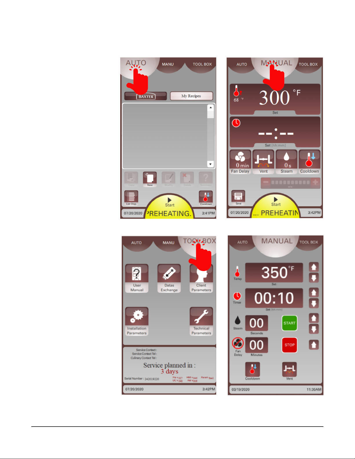
OPERATING MODES
The user display screen will default to the mode selected in the Client Parameters. Touch the mode at the
top of the screen to change the mode.
Auto Mode
Touch AUTO at the top of the
screen to access Smart Touch
Auto Mode operation (Fig. 1).
Recipes can have 1–6 steps.
Manual Mode
Touch MANUAL at the top of the
screen to access Smart Touch
Manual Mode operation (Fig.
2). Manual Mode operation can
be used for single-step recipes.
Smart™ Touch Toolbox
To access the Smart Touch
Toolbox, touch Toolbox (Fig. 3).
This mode accesses the User
Manual, Data Exchange, and
Client Parameters.
NOTE: The Smart Touch
control can also be adjusted
to operate in Classic Manual
Mode (Fig. 4). This mode
emulates the traditional Baxter
keypad control.
Fig. 1 Fig. 2
Fig. 3 Fig. 4
– 7 –
Page 8
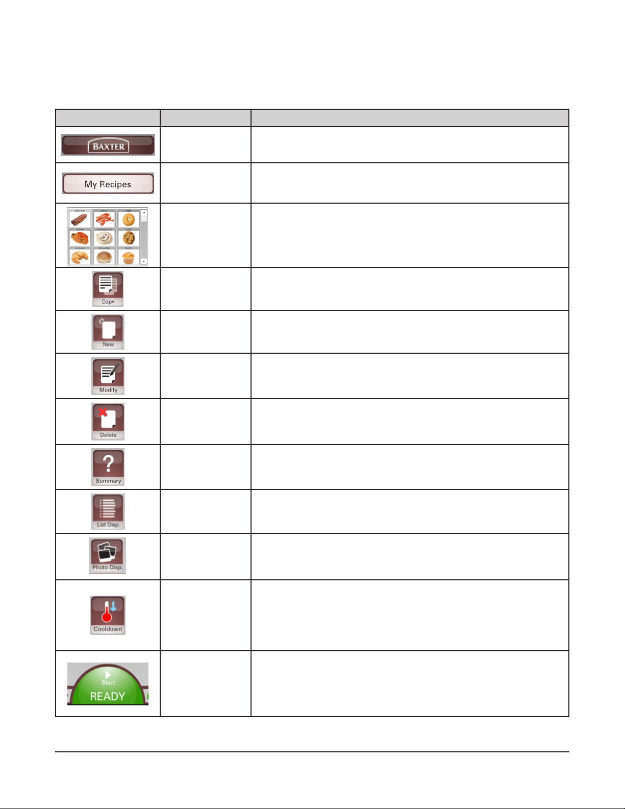
DISPLAY SCREEN BUTTONS
The Auto and Manual modes are adjusted by touching the various buttons on the display. Review the
charts below for information about each button.
Auto Mode Buttons
BUTTON NAME ACTION
Baxter Recipes
My Recipes
Recipe Selector
Copy Touch to copy a recipe.
New Touch to create a new recipe.
Modify Touch to modify a recipe.
Delete Touch to delete an existing recipe from My Recipes.
Shows preset Baxter recipes. These can be copied to My Recipes
and then modied.
Location of customer recipes. Recipes can be copied, created,
modied, or deleted here.
Shows list of all recipes as images.
Touch up/down arrow to scroll pages.
Select recipe by touching desired recipe image.
Summary
List Display
Photo Display
Cooldown
Start
Touch to enable preheating when a recipe is selected and review all
steps and bake/cook parameters of a recipe.
Touch to view all recipes in a list view alphabetically. Toggles to
Photo Display when touched.
Touch to view all recipes in as images. Toggles to List Display when
touched.
Touch to access keypad for temperature adjustments and to start a
cooldown process.
NOTE: Start button at the bottom of the display will turn blue and
scroll COOLING during a cooldown cycle. Cooldown temperature
must be set to a minimum of 25°F below oven temperature.
Touch Start to initiate a bake/cook cycle and all parameters. Oven
status will display.
Green Start button means oven is preheated.
Yellow Start button means oven is preheating.
– 8 –
Page 9
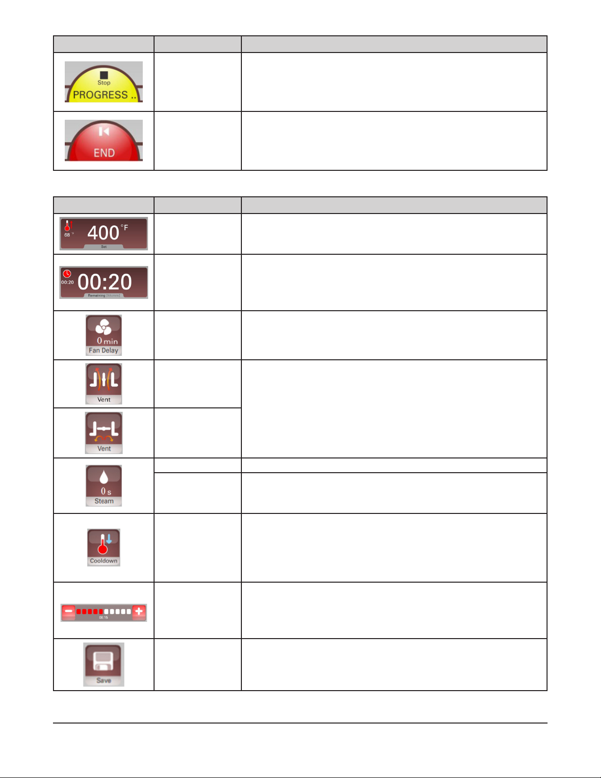
BUTTON NAME ACTION
Stop Touch Stop to end a bake/cook cycle in process.
Touch end to nish a bake/cook cycle.
End
NOTE: After bake/cook time ends, touch time display to add time
using the keypad.
Manual Mode Buttons
BUTTON NAME ACTION
Temperature
Setting Display
Timer Setting
Display
Shows set and current temperature. Touch the window to access the
keypad for temperature adjustment. Temperature can be adjusted at
any time.
Shows set and remaining time. Touch the window to access keypad
for timer adjustment.
NOTE: After bake/cook time ends, touch time display to add time
using the keypad.
Fan Delay
Vent (Open)
Vent (Closed)
Steam Burst Touch to access keypad and set steam time.
Steam Pulse
Cooldown
Add/Subtract
Time
Shows the Fan Delay Time for the current step in a recipe. Touch
the button to access keypad to change fan delay time.
Allows the cavity vent to be opened or closed during a recipe or
step. When the button is touched, the icon toggles indicating the
opened or closed setting. This feature can be programmed into a
step or manually adjusted by touching the button while a recipe is
running.
Touch and hold the Steam button for 3 seconds to access pulse
steam mode. Touch again to access keypad and set steam time and
interval.
Touch to access keypad for temperature adjustments and to start a
cooldown process.
NOTE: Start button at the bottom of the display will turn blue and
scroll COOLING during a cooldown cycle. Cooldown temperature
must be set to a minimum of 25°F below oven temperature.
Touch + / - to change time during a bake/cook cycle. Time is added
to the last step.
NOTE: After bake/cook time ends, touch time display to add time
using the keypad.
Save Touch to save current one-step recipe in My Recipes.
– 9 –
Page 10
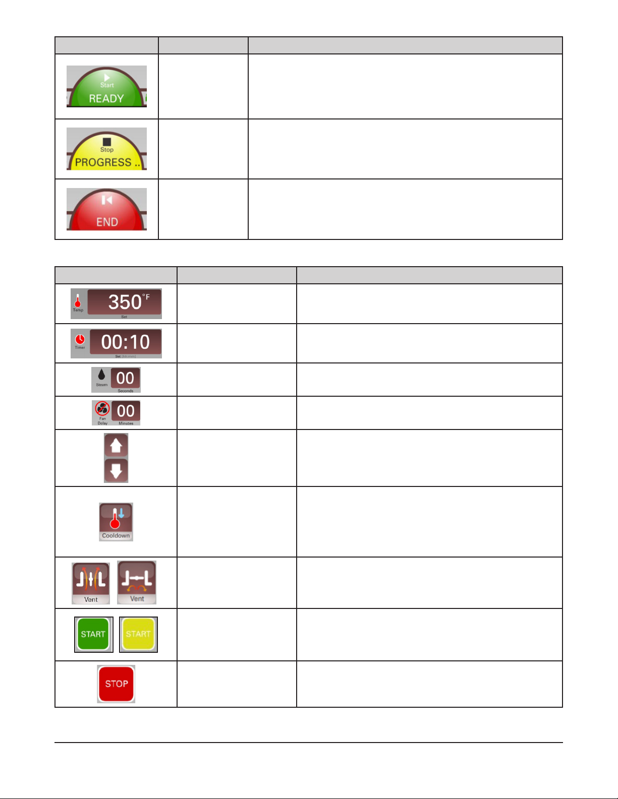
BUTTON NAME ACTION
Touch Start to initiate a bake/cook cycle and all parameters. Oven
status will display.
Start
Stop Touch Stop to end a bake/cook cycle in process.
End
Green Start button means oven is preheated.
Yellow Start button means oven is preheating.
Touch End to nish a bake/cook cycle.
NOTE: After bake/cook time ends, touch time display to add time
using the keypad.
Classic Manual Mode Display and Buttons
DISPLAY/BUTTON NAME ACTION
Shows set temperature. Use arrows to adjust
Temperature Display
Timer Display
temperature. Temperature can be adjusted at any time.
Touch window to display current temperature.
Shows set and remaining time. Use arrows to adjust time.
Touch window to display set time during a bake/cook
cycle.
Steam Display Shows set steam time. Use arrows to set steam time.
Fan Delay Display Shows fan delay time. Use arrows to set fan delay time.
Arrows Use arrows next to each display to adjust settings.
Adjust temperature to desired lower temperature using
temperature down arrow and touch Cooldown button.
Cooldown
Vent (Open/Closed) Touch button to open or close the vent.
Start
Touch the Stop button to end a cooldown process.
NOTE: Cooldown temperature must be set to a minimum
of 25°F below oven temperature.
Touch Start to initiate a bake/cook cycle and all functions.
Green Start button means oven is preheated.
Yellow Start button means oven is preheating.
Stop Touch Stop to end a current bake/cook cycle.
– 10 –
Page 11
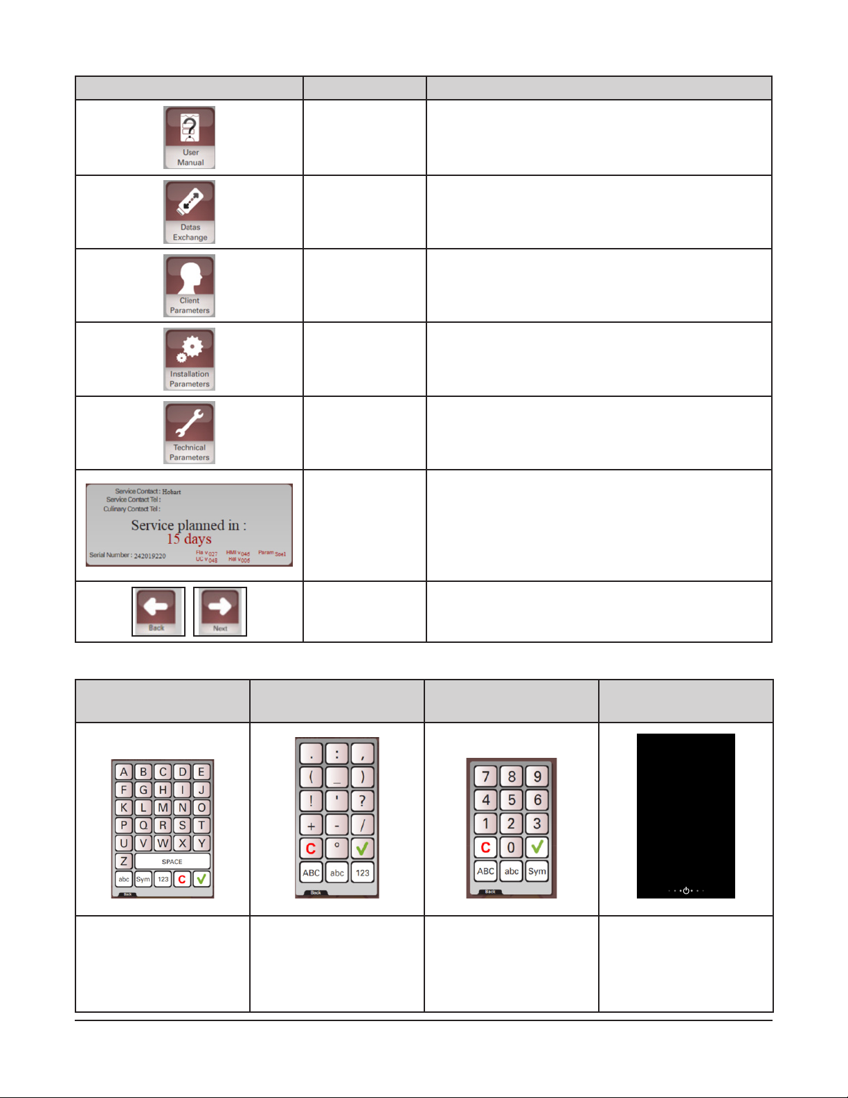
Toolbox Buttons
BUTTON NAME ACTION
User Manual
Touch to access:
• User Manual
• Auto and Manual mode training animations
• Frequently Asked Questions (FAQ)
Datas Exchange
Client Parameters
Installation
Parameters
Technical
Parameters
Maintenance
Information
Touch to access the Datas Exchange screen.
Default Password = 0000.
Touch to enter Client Parameters screen.
Default Password = 0000.
For use by Baxter authorized servicers only.
For use by Baxter authorized servicers only.
This area of the display shows:
• Service contact information
• Culinary contact information
• Service planned countdown
• Serial number
• Software versions
Screen Arrows Use Back or Next arrow to cycle through screens.
Miscellaneous Screens
Standard Keyboard Symbol Keypad 123 Keypad
Toggle caps and lower
case by touching abc
button.
Use for 13 symbols. Use for numbers. Touch screen to resume
Energy Savings
Setback Mode
normal operation.
See Client Parameters
for setback time and
temperature.
– 11 –
Page 12
USING AUTO MODE
The Auto Mode guides the user through all the oven features for recipe setup. A recipe is a set of baking/
cooking instructions (temperature, bake, steam, and fan delay settings) that the operator denes for any
baking/cooking operation. Recipes created in the Manual Mode CAN be saved. Use Auto Mode when
creating recipes to save and for multi-step recipes.
Creating a Recipe
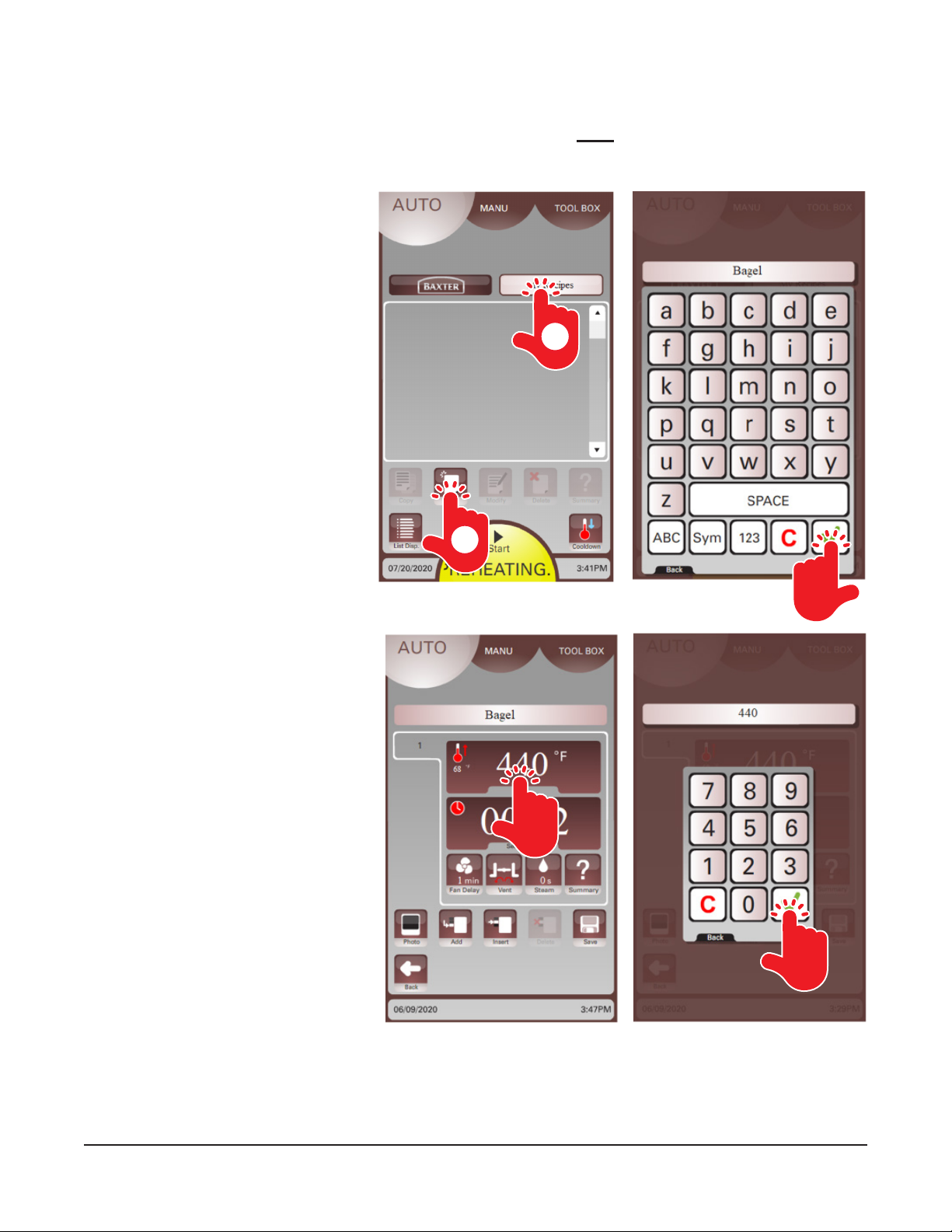
1. On the user display, touch the
AUTO button at the top and then
Touch the My Recipes button
(Fig. 5).
2. Touch the New button (Fig. 5) to
create a new recipe. A keyboard
should be displayed.
1
3. Enter the recipe name using
the keyboard (Fig. 6). Touch the
green check mark when nished.
The recipe name should appear
above the recipe window.
4. Touch the Temperature window
(Fig. 7) to set the desired
temperature for this step of the
recipe. A keypad should be
displayed.
5. Enter the desired temperature
on the keypad (Fig. 8). Touch the
green check mark button when
finished. The recipe window
should appear with the set
temperature.
2
Fig. 5
Fig. 6
Fig. 7 Fig. 8
– 12 –
Page 13
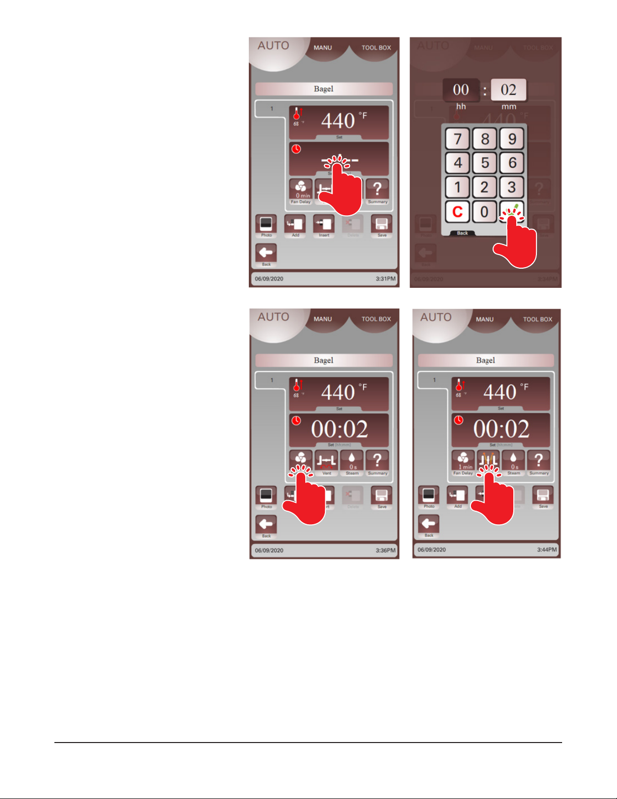
6. Touch the Time window (Fig. 9) to
set the desired bake/cook time for
this step of the recipe. A keypad
should be displayed.
7. Enter the desired bake/cook time
on the keypad (Fig. 10). Touch the
green check mark when nished.
The recipe window should appear
with the set bake/cook time.
8. Touch the Fan Delay button
(Fig. 11) and enter the fan delay
time using the keypad. The recipe
window should appear with the
set fan delay time.
Fig. 9 Fig. 10
9. Touch the Vent button (Fig. 12)
to open the vent for the total time
in the current step. The recipe
window should appear with the
desired vent icon.
Fig. 11 Fig. 12
– 13 –
Page 14
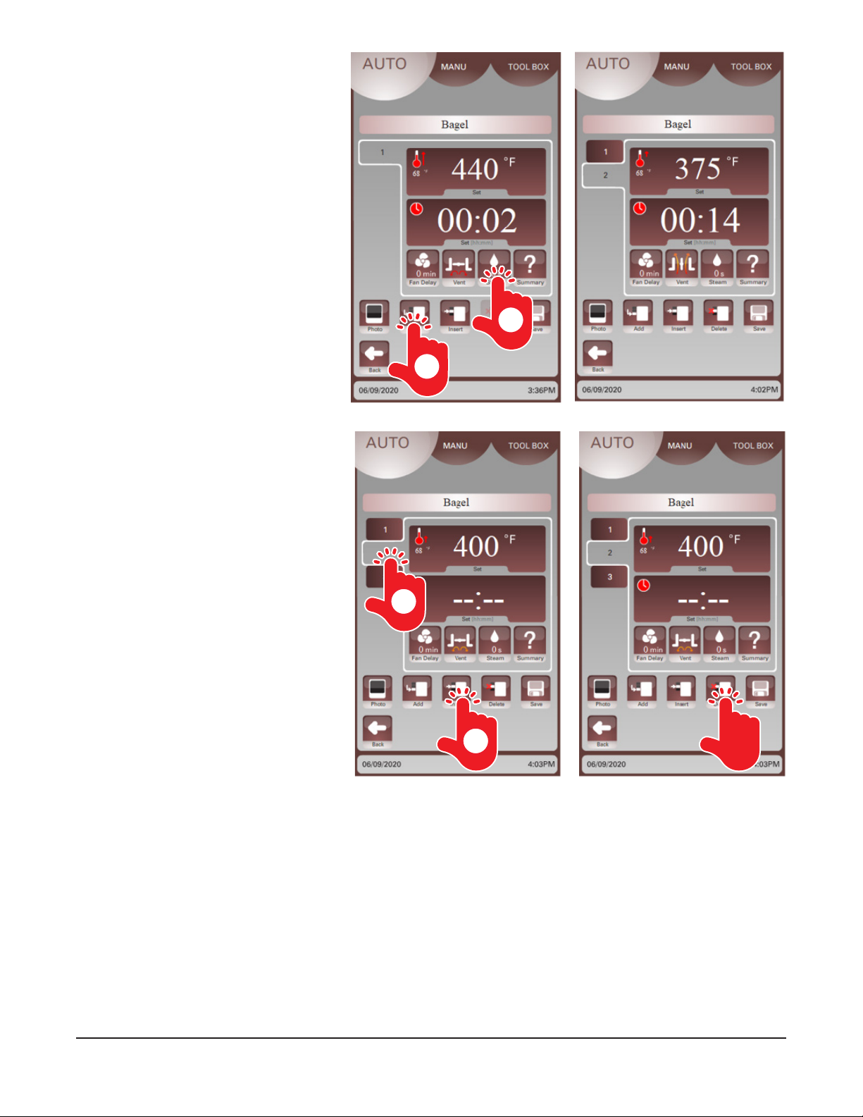
10. Touch the Steam button (Fig. 13)
and enter the steam time using the
keypad. The recipe window should
appear with the set steam time.
11. Touch the Add button (Fig. 13) to
add another step after the current
step to the recipe. The recipe
window should be displayed with
a step 2 window (Fig. 14).
12. Repeat steps 4 through 10 above
to set the temperature, time, fan
delay, vent position, and steam
time for this step of the recipe.
10
11
13. Touch the Insert button to add
a step BEFORE a current step
(Fig. 15).
14. Touch the number tab (Fig. 15)
in the recipe window to switch
between steps in a recipe.
15. Touch the Delete button (Fig. 16)
to remove a current step.
14
Fig. 13
13
Fig. 15 Fig. 16
Fig. 14
– 14 –
Page 15
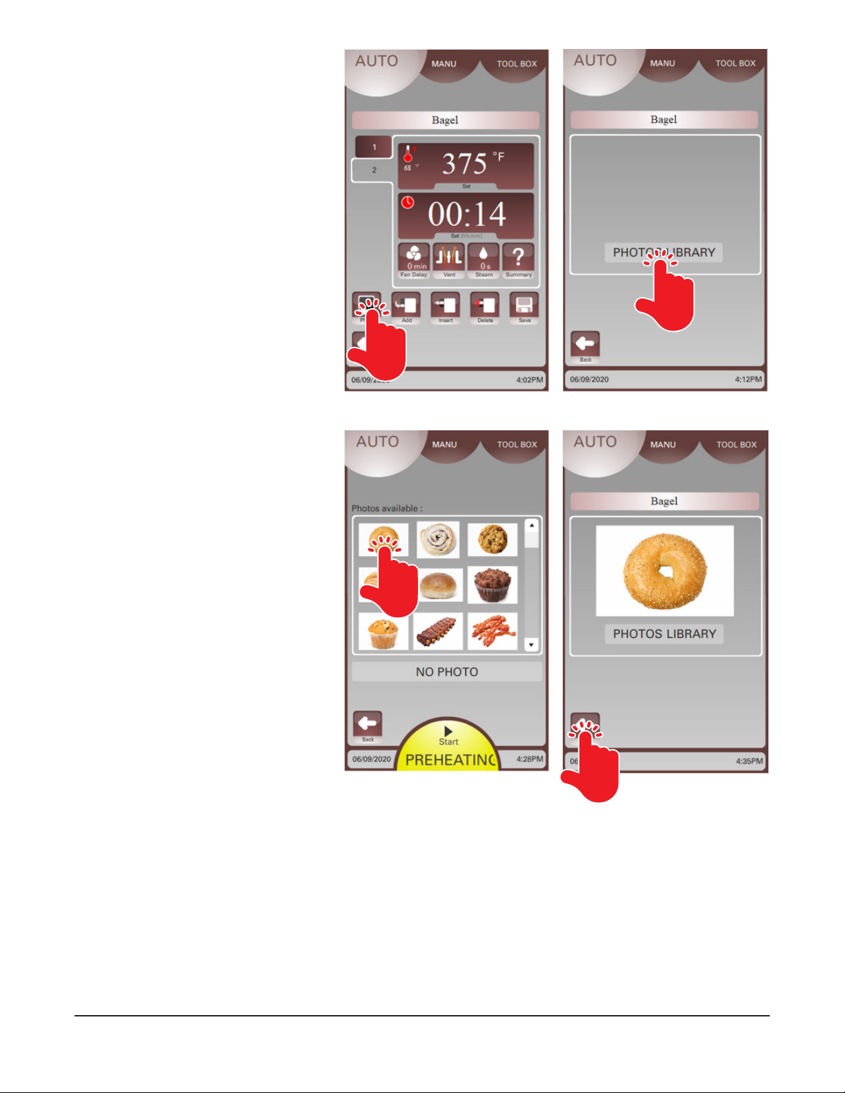
16. Touch the Photo button (Fig. 17)
to add an image from the Photos
Library to the recipe. The Photos
Library window should be
displayed.
17. Touch the Photos Library button
(Fig. 18). Available photos should
be displayed.
18. Use the up and down arrows to
view images. Touch the photo
(Fig. 19) when you have made a
selection.
Fig. 17 Fig. 18
19. The selected image will be
displayed. Touch the back arrow
(Fig. 20) to return to the recipe
window.
Fig. 20Fig. 19
– 15 –
Page 16
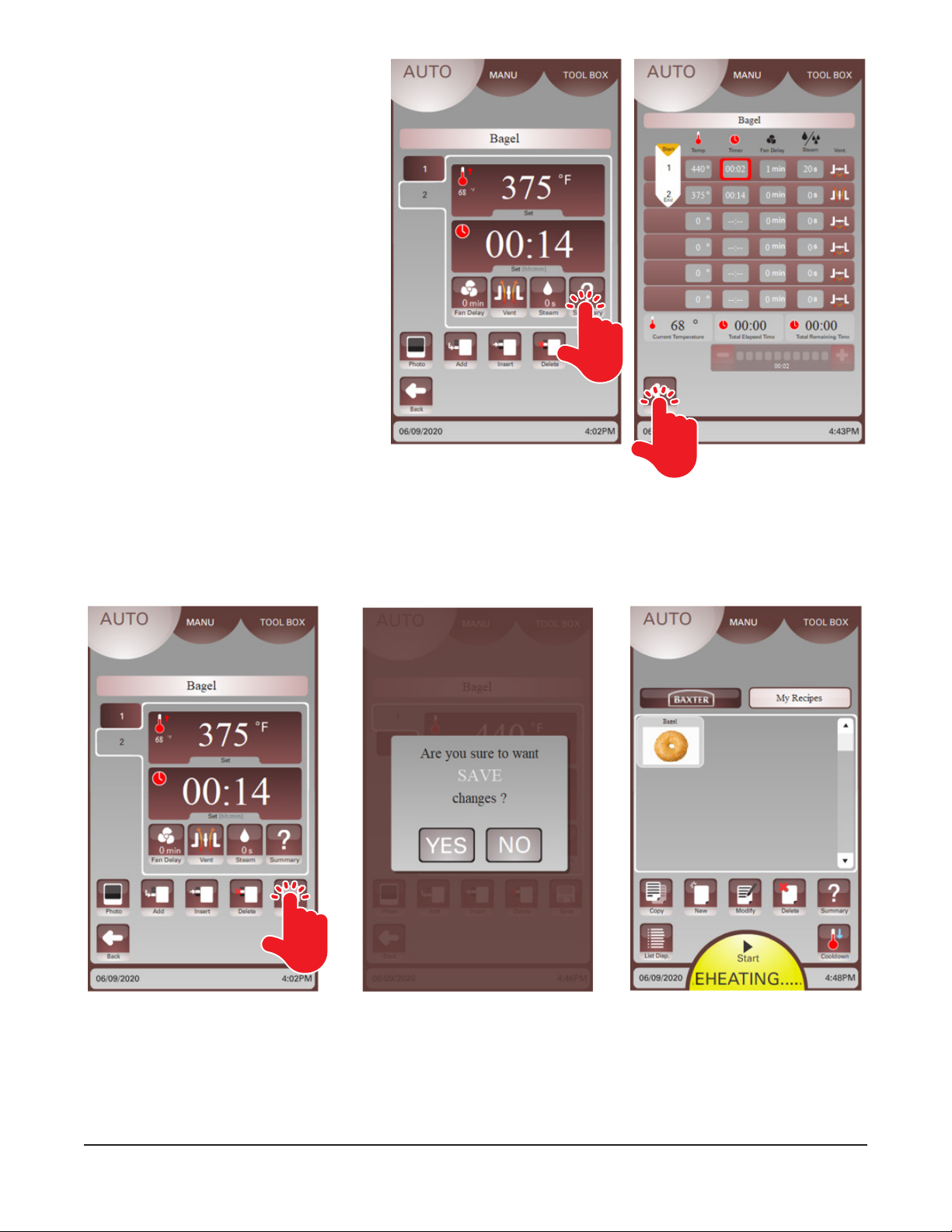
20. Touch the Summary button to
review all steps (Fig. 21). The
Summary Review window will
appear.
NOTE: The Summary Review window
will display all settings for each step in
a recipe and the total elapsed time and
remaining time in a recipe.
21. After reviewing all steps, touch the
back arrow (Fig. 22).
22. Touch the Save button (Fig. 23) to save to the My Recipes library.
Fig. 22Fig. 21
23. Touch Yes to conrm or No to edit or review the recipe (Fig. 24).
24. The recipe will now be displayed in the My Recipes window (Fig. 25).
Fig. 23
Fig. 24
– 16 –
Fig. 25
Page 17
Using a Recipe
Preset recipes are available under
the Baxter button and custom created
recipes are available under My Recipes.
Recipes can be viewed by photos or
by a list.
NOTE: Recipes can be modied before
starting the bake/cook cycle. Consider
whether the recipe should be copied
rst before modifying.
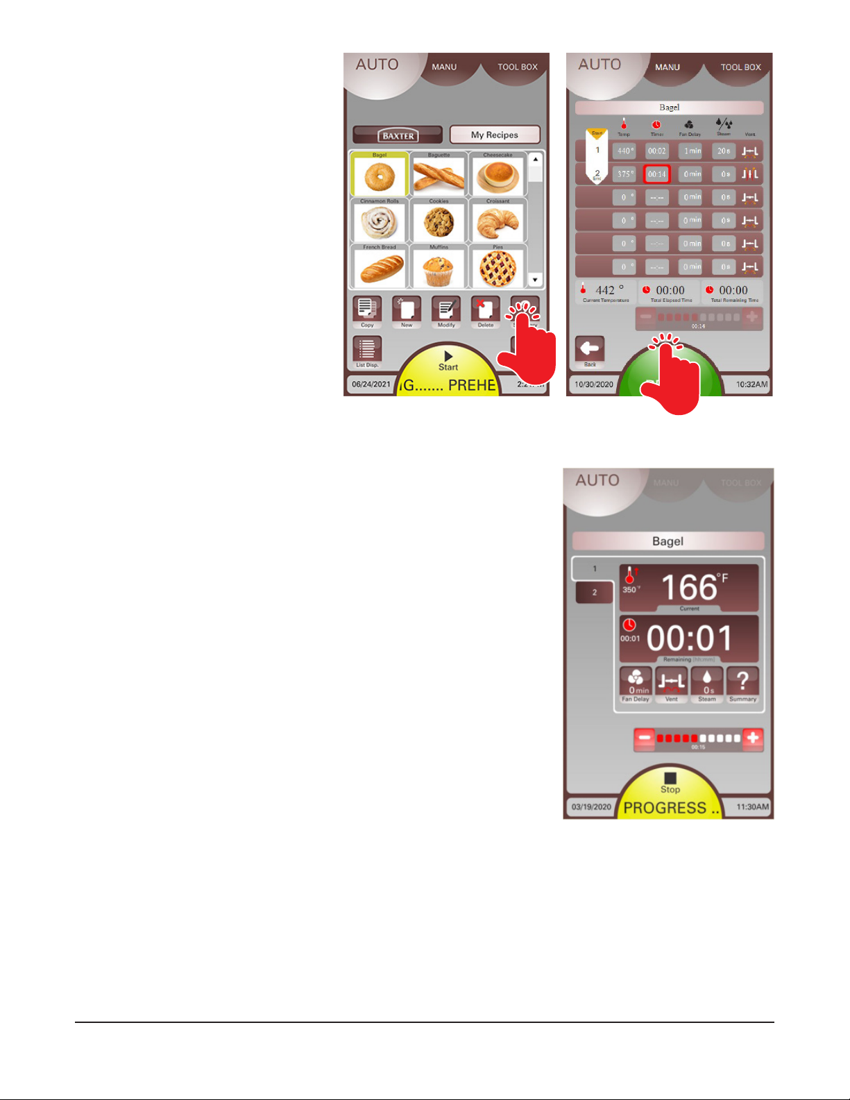
Select the recipe by touching the photo
or name in the list. The summary button
can be pressed to review the recipe
(Fig. 26). Touch Start to begin the recipe
(Fig. 27).
NOTE: A green Start button indicates
the oven is preheated. A yellow Start
button indicates the oven is preheating.
The border color around the recipe icon
will change with the start button color.
Fig. 26
Fig. 27
Viewing a Recipe in Progress
The display screen will show the progress of an actively running recipe
(Fig. 28). The recipe name, current and set temperature, remaining and
set time, fan delay time, vent status, and steam time will be displayed.
The recipe step is shown by the number on the left side of the window.
The Stop button will scroll the words IN PROGRESS. The entire recipe
can be viewed by touching the Summary button (Fig. 26).
NOTE: The Summary Review window (Fig. 27) will display all settings
for each step in a recipe and the total elapsed time and remaining time
in a recipe.
During the bake/cook cycle, time can be added or subtracted by touching
the + / - add/subtract time button.
NOTE: After bake/cook time ends, touch the time display window to add
time using the keypad.
Touch the Stop button to end a bake/cook cycle in progress.
Fig. 28
– 17 –
Page 18
MANUAL MODE
The Manual Mode guides the user through a simplied setup process without using a saved recipe. Manual
Mode can be used for single-step recipes. This can save time and be easier to use than the Auto Mode.
NOTE: The Manual Mode process can be congured in the Client Parameters to operate in Manual or
Classic Manual mode.
• Manual Mode - The user will have access to manually enter temperature, time, steam, fan delay
vent options; change time during bake/cook cycle; save one-step recipes; stop bake/cook cycle
while in process; and end bake/cycle in process.
• Classic Mode - This mode emulates the traditional Baxter controls for ovens. The user will have
access to manually enter temperature, time, steam, fan delay, and vent options, and stop bake/
cook cycle in process.
Using Manual Mode
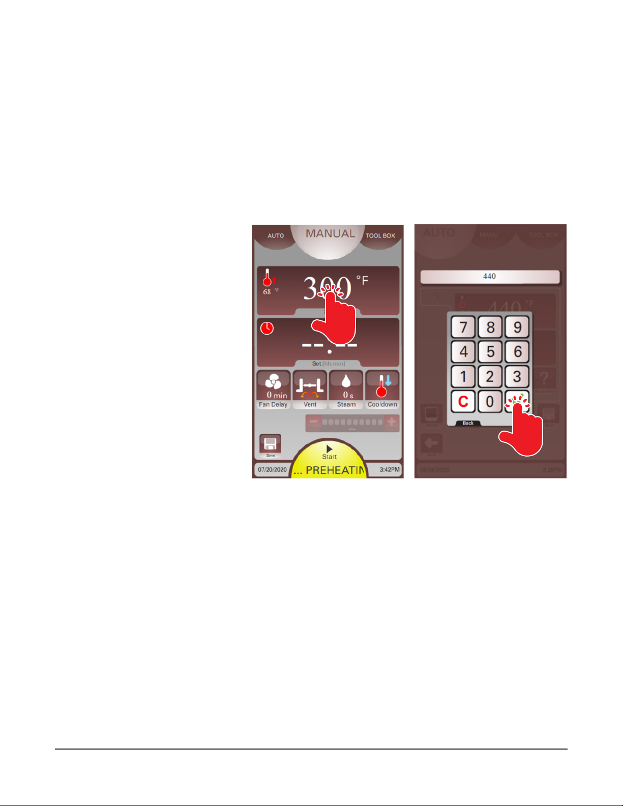
1. On the user display, touch the
MANUAL button at the top.
2. Touch the Temperature Setting
Display (Fig. 29) to set the desired
temperature. A keypad should be
displayed.
3. Enter the desired temperature
on the keypad (Fig. 30). Touch
the green check mark button
when nished. The Manual Mode
screen should appear with the set
temperature.
Fig. 29
– 18 –
Fig. 30
Page 19
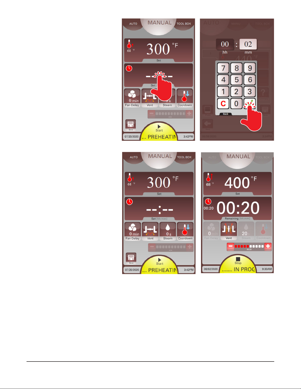
4. Touch the Timer Setting Display
(Fig. 31) to set the desired bake/
cook time. A keypad should be
displayed.
5. Enter the desired bake/cook time
on the keypad (Fig. 32). Touch the
green check mark when nished.
The Manual Mode screen should
appear with the set bake/cook
time.
6. Touch the Fan Delay button
(Fig. 33) and enter the fan delay
time using the keypad.
7. Touch the Vent button (Fig. 33) to
toggle the vent open or closed.
8. Touch the Steam button (Fig. 33)
and enter the steam time using
the keypad.
NOTE: If the oven temperature is too
high for the current operation, touch
the Cooldown button to access the
temperature setting and start a cooldown
process. The Start button will turn blue
during a cooldown process.
NOTE: If desired, touch the Save button
to save these bake/cook settings in My
Recipes. See Creating a Recipe in Auto
Mode for more details.
9. Touch Start to begin the bake/cook
cycle.
Fig. 31
Fig. 33 Fig. 34
Fig. 32
NOTE: A green Start button indicates the oven is preheated. A yellow Start button indicates the oven is
preheating.
NOTE: During the bake/cook cycle, time can be added or subtracted by touching the + / - add/subtract
time button.
NOTE: After bake/cook time ends, touch the time display window to add time using the keypad.
10. Touch the Stop button (Fig. 34) to end a bake/cook cycle in progress.
– 19 –
Page 20
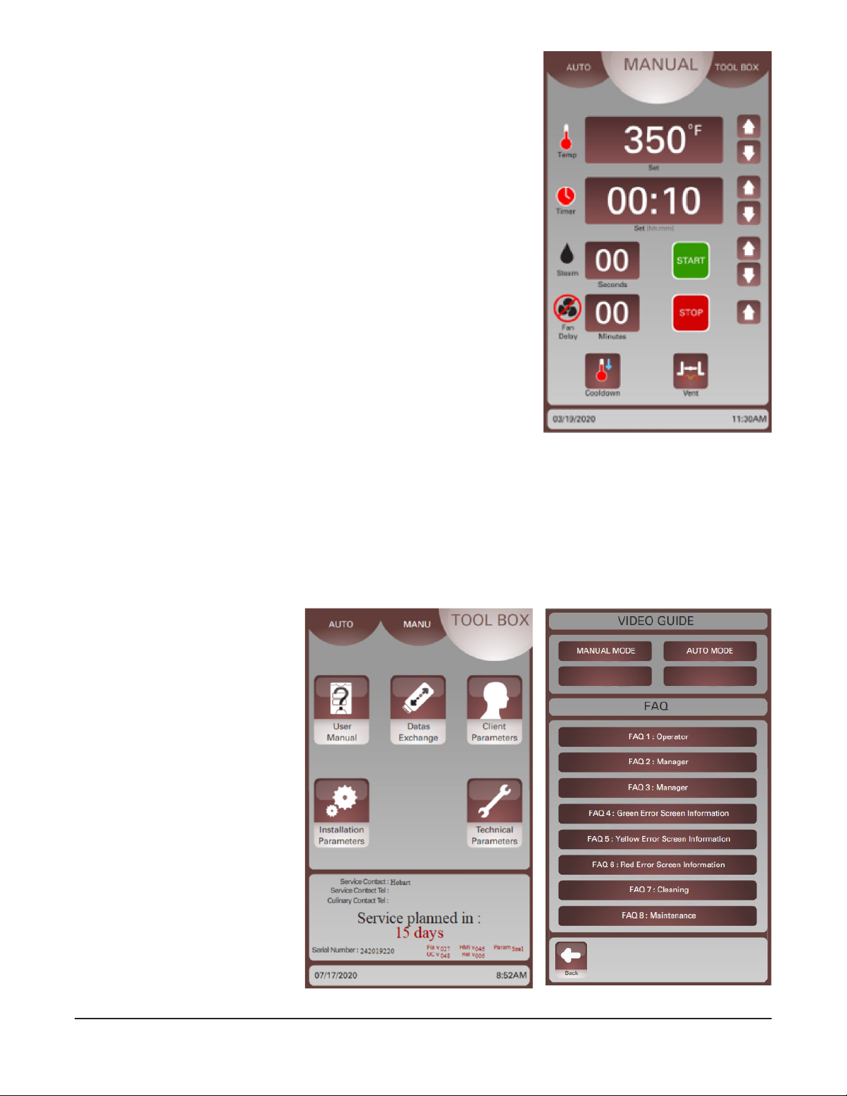
Using Classic Manual Mode
NOTE: The Manual Mode process can be congured in the Client
Parameters to operate in Classic Manual Mode.
1. On the user display, touch the MANUAL button at the top. The
Classic Manual Mode should display (Fig. 35).
2. Touch the Arrow buttons next to the Temperature Display, Timer
Display, Steam Display, and Fan Delay Display to adjust the
settings.
3. Touch the Vent button to toggle the vent setting open or closed.
NOTE: If the oven temperature is too high for the current operation,
adjust the temperature down using the temperature down arrow
and touch the Cooldown button. Touch the Stop button to end the
cooldown process.
4. Touch Start to begin the bake/cook cycle.
NOTE: A green Start button indicates the oven is preheated. A yellow
Start button indicates the oven is preheating.
NOTE: During the bake/cook cycle, settings can be adjusted any
time by touching the Arrow buttons.
NOTE: During the bake/cook cycle, touch the Temperature Display
to show the current oven temperature. Touch the Timer Display to view the set time.
Fig. 35
5. Touch the Stop button to end a bake/cook cycle in progress.
USING SMART TOUCH TOOLBOX MODE
This Smart Touch Toolbox Mode (Fig. 36) is used to access the User Manual, Data Exchange, and
Client Parameters Screens. The Installation Parameters and Technical Parameters are for use by Baxter
authorized servicers only.
User Manual Screen
The User Manual Screen (Fig. 37)
provides access to the user
manual, auto and manual mode
training animations and FAQ.
Touch MANUAL MODE or AUTO
MODE to view animations on
how to use each mode. Touch
the FAQ to review information
about the topics listed. Touch the
Back Arrow button to return to the
Toolbox screen.
Fig. 36
– 20 –
Fig. 37
Page 21
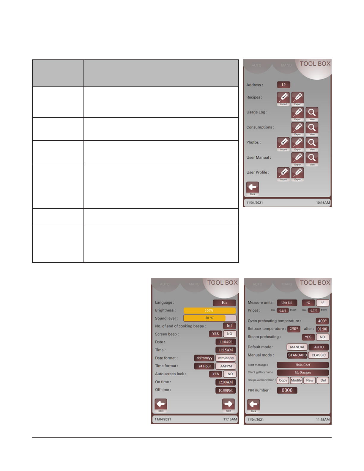
Data Exchange Screen
The Data Exchange Screen is used to allow the user to import and export various data types via Universal
Serial Bus (USB) drive. Touch the button on the screen for the data parameter to import, export, or view.
Insert the USB drive before touching any buttons. See the table below for information about each data type.
Data
Exchange
Additional Information
Parameter
Recipes Recipes can be imported and exported via a USB drive.
Any existing recipes will be erased that have the same
name. See Smart Touch Perconal Computer (PC) Software manual for PC-based recipe management.
Usage Log Press view button to see a history of recipe usage or
manual mode usage. History can be exported to a USB
as a .csv le.
Consumptions Consumptions can be exported as a .csv le and viewed
on a computer in Excel or Smart Touch PC Software.
See Smart Touch PC Software manual for instructions.
Photos Photos can be imported and exported via a USB drive.
Importing photos will erase any photo with the same
name. Each image will have two photos saved. One for
the recipe image and one for the welcome screen. See
Smart Touch PC Software manual for PC-based photo
management.
User Manual The FAQ User Manual can be exported and viewed on a
computer or printed.
User Prole The oven’s User Prole can be imported and exported
via a USB drive. User Prole information includes
recipes, photos, client parameters, and maintenance
contacts. See Smart Touch PC Software manual for PCbased oven management.
Fig. 38
Touch the Back Arrow button to return to the Toolbox screen.
Client Parameters Screen
The Client Parameters Screen is used
with default operation settings for the
oven. There are two screens (Fig. 39
and Fig. 40). Touch the Next and Arrow
buttons to navigate through the screens.
Refer to the Parameters Table for details
about each setting.
Fig. 39 Fig. 40
– 21 –
Page 22
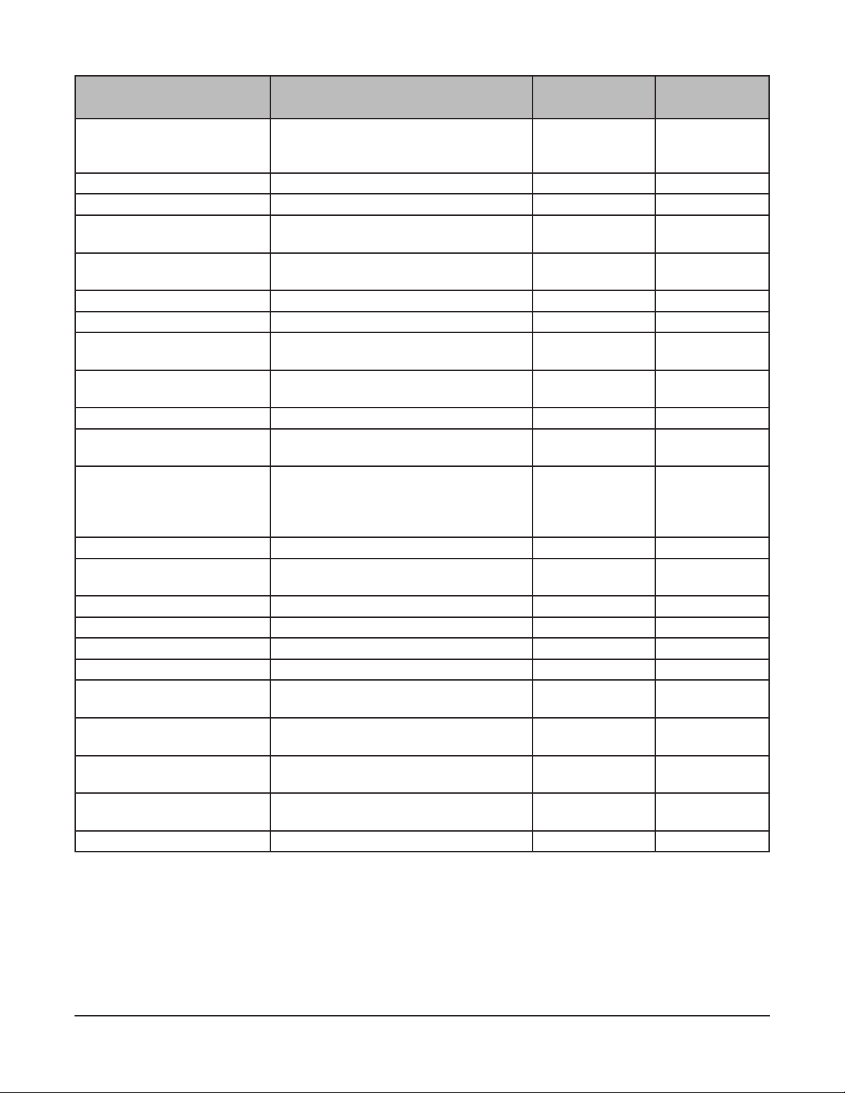
Parameters Table
PARAMETER DESCRIPTION DEFAULT
Language Language selection English (En) English (En)
Brightness Adjust screen brightness 100% 10 - 100%
Sound level Sound level adjustment 80% 0 - 100%
No. of end of cooking beeps Adjust the number of beeps at the end of
a bake/cook cycle
Screen beep Turn o/on screen beeps when touched Yes Yes = On
Date Set current date - Time Set current time - Date format Set the format the date is displayed on
the screen
Time format Set the format the time is displayed on
the screen
Auto screen lock Enables/disable screen lock No Yes or No
On Time Start of time range that oven can be
used.
O Time End of time range that oven can be
used.
Note: If O time equals On time, the
feature is disabled.
Measure units Temperature unit selection °F °F or °C
Prices Set the dollar value of the unit of power Elec: [$0.15/kWh]
Oven preheat temperature Default preheat temperature 400°F 50 -525°F
Setback temperature Temperature setback value 250°F 50 –300°F
Steam preheating N/A N/A N/A
Default mode Default mode oven will start on Manual Manual or Auto
Manual mode Default manual mode Classic Standard or
Start message Welcoming message when oven is
energized
Client gallery name Default client recipe name My Recipes Up to 26
Recipe authorization Enables/disables recipe copy, modify,
new, or delete recipes
Pin number Pin number to access Client Parameters 0000 0000 - 9999
Innite 1 -11
mm/dd/yy mm/dd/yy
AM/PM AM/PM
12:00 AM All time.
10:00 PM All time.
Gas: [$1/therm]
Hello Chef Up to 26
All enabled Enable or
RANGE or
VALUE
Spanish (Esp)
French (Fr)
11 = Innite
No = O
dd/mm/yy
24 Hour
Classic
characters
characters
disable
– 22 –
Page 23
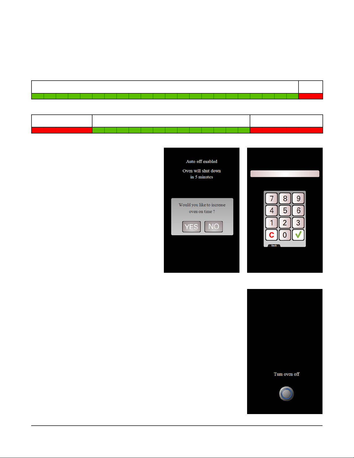
Auto O
The Auto On/Auto O times shown in Client parameters allow the user to set a useable time frame for the
oven. If the oven is outside of these times, the oven will shut down automatically.
NOTE: This feature can be disabled by setting both values to 12:00AM.
Example #1: The default ON value of 12:00AM and OFF value of 10:00PM allows the oven to be used
from 12am to 10pm.
12AM 1AM 2AM 3AM 4AM 5AM 6AM 7AM 8AM 9AM 10AM 11AM 12PM 1PM 2PM 3PM 4PM 5PM 6PM 7PM 8PM 9PM 10PM 11PM
ON OFF
Example #2: ON value of 5:00AM and OFF value of 6:00PM allows the oven to be used from 5am to 6pm.
12AM 1AM 2AM 3AM 4AM 5AM 6AM 7AM 8AM 9AM 10AM 11AM 12PM 1PM 2PM 3PM 4PM 5PM 6PM 7PM 8PM 9PM 10PM 11PM
OFF ON OFF
When the oven is ON and reaches the Auto OFF
time the following “Auto O” screen (Fig. 41)
will appear with an audible alarm. To continue
to use the oven, press YES and enter the Client
password (Default: 0000) and press the green
check mark (Fig. 42). This will allow the oven
to operate for another hour. After an hour the
“Auto O” screen (Fig. 41) will reappear asking
if you would like to continue using the oven.
If you are done using the oven you can turn
the oven o.
Fig. 41 Fig. 42
If ve minutes has expired on the “Auto O” screen (Fig. 41) the screen the
right (Fig. 43) will appear. If you are done using the oven, turn the oven o.
To use the oven again turn the oven o and back on.
– 23 –
Fig. 43
Page 24

SHUTDOWN
The rack oven and its parts are hot. Use care when operating, servicing, or cleaning
the rack oven.
Hot air and steam are released from the oven interior when the loading door is
opened. To avoid burns, open the door slowly and keep clear of the opening.
NOTE: Before restarting a gas oven, the power switch and the gas burner valve must be o for a minimum
of 5 minutes.
1. Remove all remaining product.
NOTE: Vent can be used to evacuate steam from oven.
2. Allow the oven to cool, then press the POWER ON/OFF button. If desired, quicker cooldown time
can be accomplished through the use of the Cooldown button.
3. Clean the baking chamber. See Cleaning page 27.
4. For lengthy shutdowns, disconnect the main power and shut o the gas and water supply.
RESTARTING OVEN
NOTE: Before restarting a gas oven, power switch and gas burner valve must be o for a minimum of
5 minutes.
1. Press the POWER ON/OFF button to turn the oven on.
2. Adjust temperature as required.
– 24 –
Page 25
TROUBLESHOOTING
BURNERS WILL NOT LIGHT ON GAS OVEN
1. Check that the loading door is shut and the door switch is actuated.
2. Press the OFF button to turn the oven o and wait 5 minutes.
3. Make sure the gas shuto valve and gas valve are in the ON position.
4. Press the ON button to turn the oven back on.
If the above suggestions do not remedy the problem, contact a Baxter authorized service oce.
OTHER TROUBLESHOOTING TOPICS
Condition Cause Action
Oven circulation fan is running but
oven is turned o.
Rack does not lift and rotate. Bake time has not been entered
Oven is in Cooling mode. Close oven door to cancel Cooling
mode. If door was not open, contact
your local Baxter authorized service
oce.
Enter time and touch Start. If
in timer and/or timer has not been
started.
problem persists, contact your local
Baxter authorized service oce.
ERROR SCREEN INFORMATION
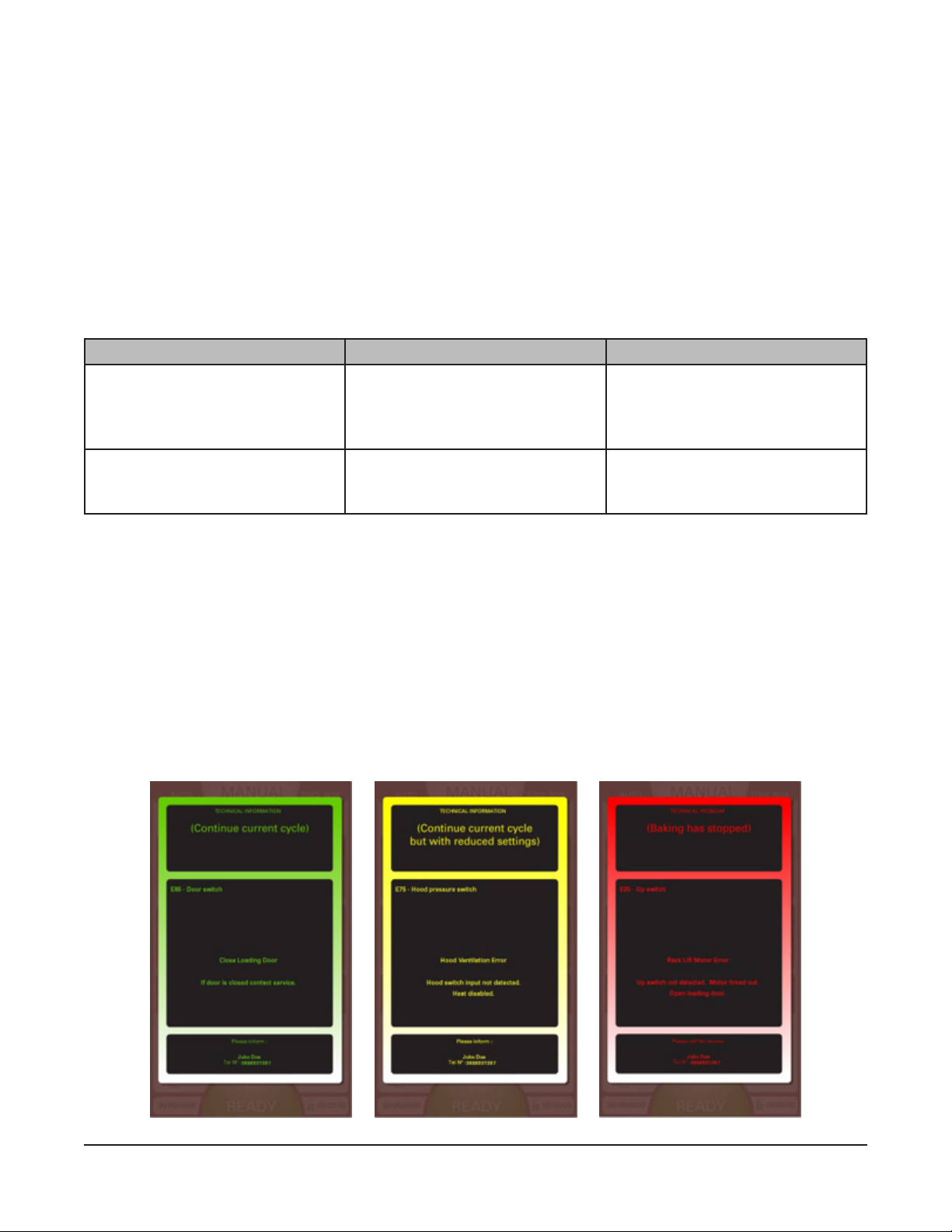
There are three error screen types.
The Green Error Screen (Fig. 44) is a basic reminder that a task has not been completed. Touch the
screen to clear the error.
The Yellow Error Screen (Fig. 45) alerts the user to a problem, however a bake/cook cycle can continue
with reduced settings. Yellow errors may include notication to resolve the issue. The error screen can
be hidden by tapping the screen. The error screen will reappear after 10 minutes if the problem persists.
The Red Error Screen (Fig. 46) alerts the user to a problem that needs to be xed before any heating or
bake/cook cycle can continue. The error screen cannot be disabled until the problem is resolved. Turn o
power to the oven and contact a Baxter authorized servicer.
Fig. 44 Fig. 45 Fig. 46
– 25 –
Page 26
COLOR CODE DESCRIPTION Action
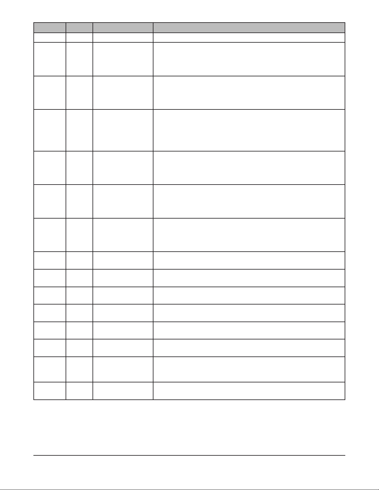
Green E85 Close Loading Door Close door. If door is closed, contact a Baxter authorized servicer.
Yellow E5 Heating Error Manual reset high temperature limit tripped. Heat disabled.
• Bake/cook cycle can continue but heat is disabled. Bake/cook
time may need to be extended.
• Contact a Baxter authorized servicer to resolve issue.
Yellow E6 Heating Error
(Gas Ovens Only)
Yellow E10 Heating Error Oven is heating slow. If burner is not running, try opening and
Yellow E11 Heating Error Oven is heating slow.
Yellow E35 Rack Rotation
Motor Error
Yellow E75 Hood Ventilation
Error
(Gas Ovens Only)
Red E8 Heating Error Temperature sensor failure. Heat disabled.
Red E9 Heating Error High temperature detected. Shut o gas and/or breakers.
Red E15 Convection Fan
Error
Red E25 Rack Lift Motor
Error
Red E26 Rack Lift Motor
Error
Red E27 Rack Limit Switch
Error
Red E76 Hood Ventilation
Error
(Gas Ovens Only)
Red E95 Electronics
Overheated
Manual reset rollout switch tripped. Heat is disabled.
• Bake/cook cycle can continue but heat is disabled. Bake/cook
time may need to be extended.
• Contact a Baxter authorized servicer to resolve issue.
closing the loading door.
• Bake/cook cycle can continue but heat is disabled. Bake/cook
time may need to be extended.
• Contact a Baxter authorized servicer to resolve issue.
• Bake/cook cycle can continue but heat is disabled. Bake/cook
time may need to be extended.
• If problem continues, contact a Baxter authorized servicer.
No rotation detected. Open loading door and check for rack/pan
jam.
• If there is no rack/pan jam or problem continues, contact a Baxter
authorized servicer.
Hood switch input not detected. Heat disabled.
• Bake/cook cycle can continue but heat is disabled. Bake/cook
time may need to be extended.
• Contact a Baxter authorized servicer to resolve issue.
• Contact a Baxter authorized servicer to resolve issue.
• Contact a Baxter authorized servicer to resolve issue.
Convection fan overheated. Motor timed out and heat disabled.
• Contact a Baxter authorized servicer to resolve issue.
Up switch not detected. Motor timed out.
• Contact a Baxter authorized servicer to resolve issue.
Down switch not detected. Motor timed out.
• Contact a Baxter authorized servicer to resolve issue.
Detecting up and down limits at the same time. Motor timed out.
• Contact a Baxter authorized servicer to resolve issue.
Possible hood switch failure. Heat disabled.
• Contact a Baxter authorized servicer to resolve issue.
Board temperature exceeded limit.
• Contact a Baxter authorized servicer to resolve issue.
– 26 –
Page 27

CLEANING
Disconnect the electrical power to the machine and follow lockout / tagout procedures.
There may be multiple circuits. Be sure all circuits are disconnected.
The rack oven and its parts are hot. Use care when operating, servicing or, cleaning
the rack oven.
Hot air and steam are released from the oven interior when the loading door is
opened. To avoid burns, open the door slowly and keep clear of the opening.
• Allow the oven to cool.
• Clean the outside of the oven daily with a clean, damp cloth.
• Remove rack(s) and clean as you would any cooking utensil. Use warm, soapy water, and a brush.
Rinse with clear water and dry with a clean cloth.
• Use care when cleaning around sensitive interior parts such as probes, sensors, or the rotating
mechanism.
• Using a clean cloth and warm, soapy water, wash the stainless steel interior of the oven. Rinse
with clear water and dry with a clean cloth.
• Gently scrape heavy buildup o door glass. Residue can be removed with a glass cleaner when
oven is cool.
• Clean hood lters (if equipped) with soap and warm water.
• Do not use oven cleaners or steel wool on stainless steel surfaces. Never spray down the oven
with water or steam.
• Never use cleaners that contain chlorine. Chlorine corrodes stainless steel.
– 27 –
Page 28

MAINTENANCE
Disconnect the electrical power to the machine and follow lockout / tagout procedures.
There may be multiple circuits. Be sure all circuits are disconnected.
The rack oven and its parts are hot. Use care when operating, servicing, or cleaning
the rack oven.
Hot air and steam are released from the oven interior when the loading door is
opened. To avoid burns, open the door slowly and keep clear of the opening.
GENERAL
As Needed
• Inspect the area around the oven. The area must be free and clear from combustibles. There must
be no obstructions to the air ow.
Daily
• Clean exterior (See Cleaning page 27).
Weekly
• Clean the oven interior and remove loose debris (See Cleaning page 27).
• Clean the windows.
• Empty grease catcher (if equipped).
Monthly
• Clean exhaust hood lters (if equipped) with soap and water.
Bi-Monthly
• Owner Preventive Maintenance (PM) Procedure.
Annually
• On gas ovens, check the ue to be sure it is free of obstructions.
PREVENTIVE MAINTENANCE
The OV520 Rack Oven must be kept on a regular preventive maintenance schedule. Ovens require
specic preventive maintenance based on usage and environmental factors. The failure to have the oven
properly maintained by following recommended preventive maintenance procedures may result in higher
repair costs, shortened equipment life, or unsafe operating conditions.
It is the owner’s responsibility to make sure preventive maintenance is performed on the rack oven. This
will ensure continued safe and reliable operation. Contact an authorized Baxter service oce to provide
this skilled service for you.
SERVICE AND PARTS INFORMATION
Contact your Baxter authorized service oce.
– 28 –
Page 29
OWNER PREVENTIVE MAINTENANCE PROCEDURE
INTRODUCTION
This customer PM section includes procedures to inspect for proper operation and cleaning of components.
Owner Preventive Maintenance Procedures are written for gas ovens. They can also be used for electric
ovens by omitting the steps that refer to components found only on gas ovens. To maintain the safety and
performance of bakery ovens, a program of scheduled periodic maintenance must be implemented. It is
the sole responsibility of the user to establish, schedule, and enforce such a program. Although the service
interval will vary depending on the environment in which the equipment is operating, it is recommended
that PM be performed and all safety devices are checked at a minimum of 12-month intervals. Check with
the authority having local jurisdiction if there are specic maintenance requirements specied by local,
state, or national codes. A convenient PM Checklist is provided at the end of this section.
NOTE: This PM procedure does not discuss repair or replacement of components. Upon completion of
the PM procedure, you will need to contact a qualied servicer for any needed repairs.
Tools Used for Inspection Procedure
• Standard set of hand tools
• Vacuum cleaner - shop vac
PREVENTIVE MAINTENANCE PROCEDURE
Disconnect the electrical power from the machine and follow lockout / tagout
procedures. There may be multiple circuits. Be sure all circuits are disconnected.
Shut o the gas before servicing the unit.
Certain procedures in this section may require electrical test or measurements
while power is applied to the machine. Exercise extreme caution at all times. If test points are not
easily accessible, disconnect power and follow lockout/tagout procedures, attach test equipment,
and reapply power to test.
Lamps
Inspect Oven Lamps
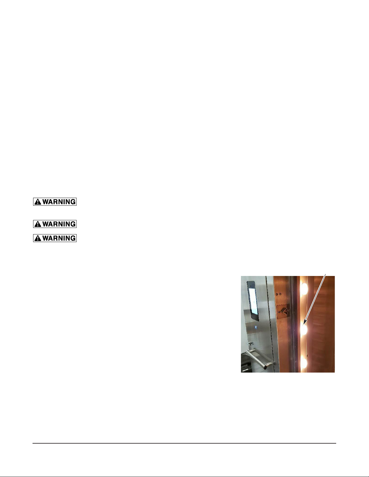
1. Lamps should be on when oven is powered.
2. If not, replace lamps (Fig. 47).
A. Remove lens cover by turning out of lamp
housing.
B. Remove oven lamp by turning lamp out of
lamp socket.
3. Reverse the procedure to install new lamps.
Fig. 47
– 29 –
Page 30
Clean and Vacuum Components and Control/Burner Compartment Area (Gas Only)
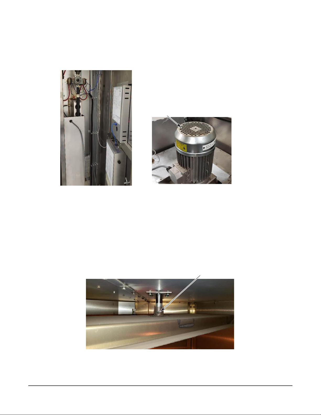
1. Clean the control/burner compartment (Fig. 48) area of dust and/or lint accumulation.
2. Vacuum the control/burner compartment oor of dust and/or lint accumulation.
3. Gain access to the top of oven and clean dust that may have accumulated on top of circulation blower
motor (Fig. 49) and motor cooling fan.
Burner Compartment
Clean Area
Fig. 48
Rack Lift and Rotation Assemblies
1. Check rack lift assembly for proper operation.
A. Open door. Rack lift should lower to correct height of rack and be in forward loading position
to accept rack entry.
B. The oven rack should be easily rolled in and out of oven and the wheels completely o the
oven oor when raised.
2. Tighten all set screws in carrier (Fig. 50).
A. Check and tighten all set screws on carrier.
Fig. 49
Set Screws
Fig. 50
– 30 –
Page 31
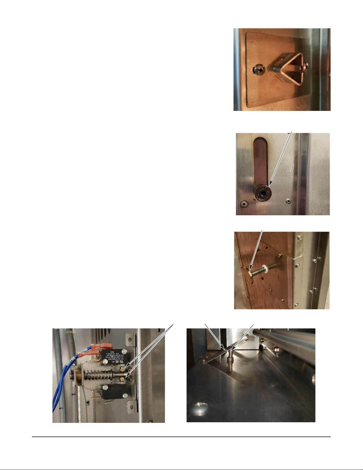
Inspect Door Components
1. Check loading door latch.
A. Check door gasket for good condition. If door gasket
needs replacement, contact your local Baxter authorized
service oce.
B. Check that the loading door lock ramps are clean (Fig. 51)
and rollers on the door move up and down and spin
freely (Fig. 52).
C. Adjust latch ramps in or out by loosening the
two screws. DO NOT REMOVE THEM.
Slide ramp in or out to loosen or tighten
door (Fig. 51).
D. Tighten screws.
2. Check door sweep.
A. The door sweep should hit the oor evenly across door
width when door is in the closed position.
B. Turn oven on.
C. If air (or steam) blows out from underneath the door, door
will need to be adjusted. If door sweep needs replacement
or adjustment, contact your local Baxter authorized
service oce.
3. Check interior door release (Fig. 53) for proper operation.
4. Check door switch for proper operation.
Door Lock Ramp
Fig. 51
Door Roller
Fig. 52
Interior Door Release
A. When door switch actuator rod is in the open position
(door open), the door switch rollers should be positioned
on the small part of the rod (Fig. 54).
Door Switch Rollers
Bracket
Fig. 53
Rod
Fig. 54
– 31 –
Page 32
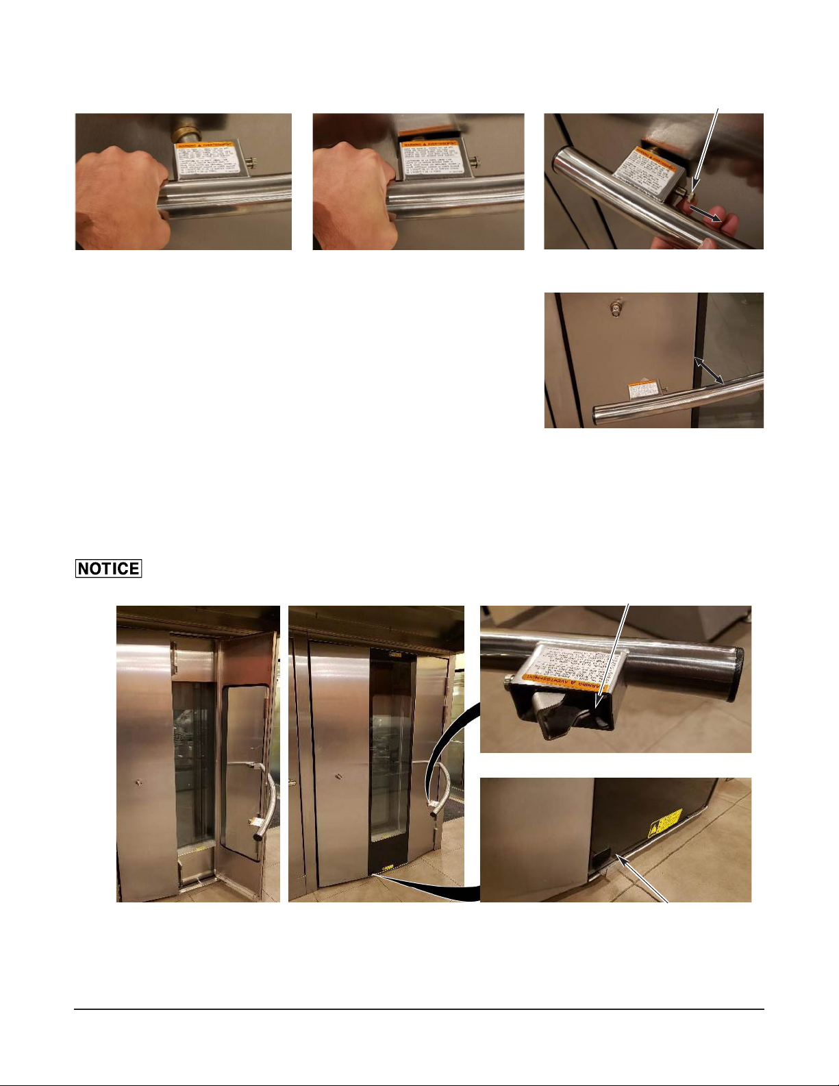
5. Check door handle operation.
A. Pull out on door handle (Fig. 55) to open door, then push door shut (Fig. 56). If the door is too
hard to open or close, see door lock ramps adjustment (Fig. 51).
Lock Pin
Fig. 55
6. Clean door glass.
A. With the loading door shut, pull door handle lock pin out
(Fig. 57).
B. Pull door handle out (Fig. 58).
C. Swing handle open (Fig. 59).
NOTE: Make sure not to dent door on hinged side.
D. Check that there is no residue buildup on the handle lock
mechanism (Fig. 59).
NOTE: The handle for the glass is located at the top or bottom of glass depending on door hinge
side.
E. Pull out on handle (Fig. 59) to open glass door. If glass door needs to be adjusted, contact your
local Baxter authorized service oce.
Failure to contact service for glass door adjustment may result in the glass breaking.
Fig. 56
Fig. 57
Fig. 58
Lock Mechanism
Fig. 59
– 32 –
Door Glass Handle
Page 33
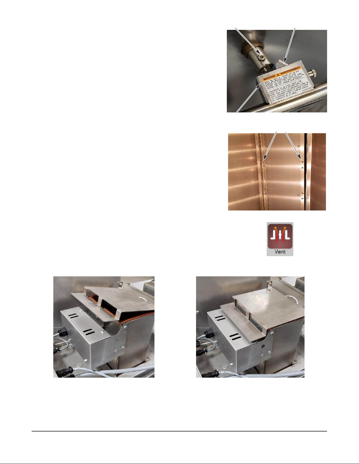
F. To close the glass door, simply push shut.
G. To close handle, the lock mechanism needs to be in the
unlock orientation (Fig. 60).
NOTE: If lock is not in the unlock orientation, pull lock pin
out and rotate lock to the unlock orientation.
H. Place lock box over hex bolt and slowly push
handle into door (Fig. 60). Check to see
if the handle latch engaged by opening door
(Fig. 61). Repeat if necessary.
Hex Bolt
Lock Pin
Inspect Air Louvers
1. Check air louvers (shutters) (Fig. 61) inside oven and
tighten any loose screws.
2. Check oven interior and tighten or replace loose or missing
panel screws. Also check oor anchors.
Inspect Cavity Vent
1. Check cavity vent for proper operation.
A. Touch Vent button (Fig. 62) on the control panel to
open vent and then touch VENT again to close vent.
B. Visually check that vent opens (Fig. 63) and closes
(Fig. 64) when button is touched.
C. Check that vent gasket is intact.
Vent Open
Vent Closed
Lock Box
Fig. 60
Shutters
Fig. 61
Fig. 62
Fig. 63
Fig. 64
Visually Inspect Electrical Connections
1. Inspect all wiring connections for discoloration. If discoloration is visible, contact your local Baxter
authorized service oce.
– 33 –
Page 34
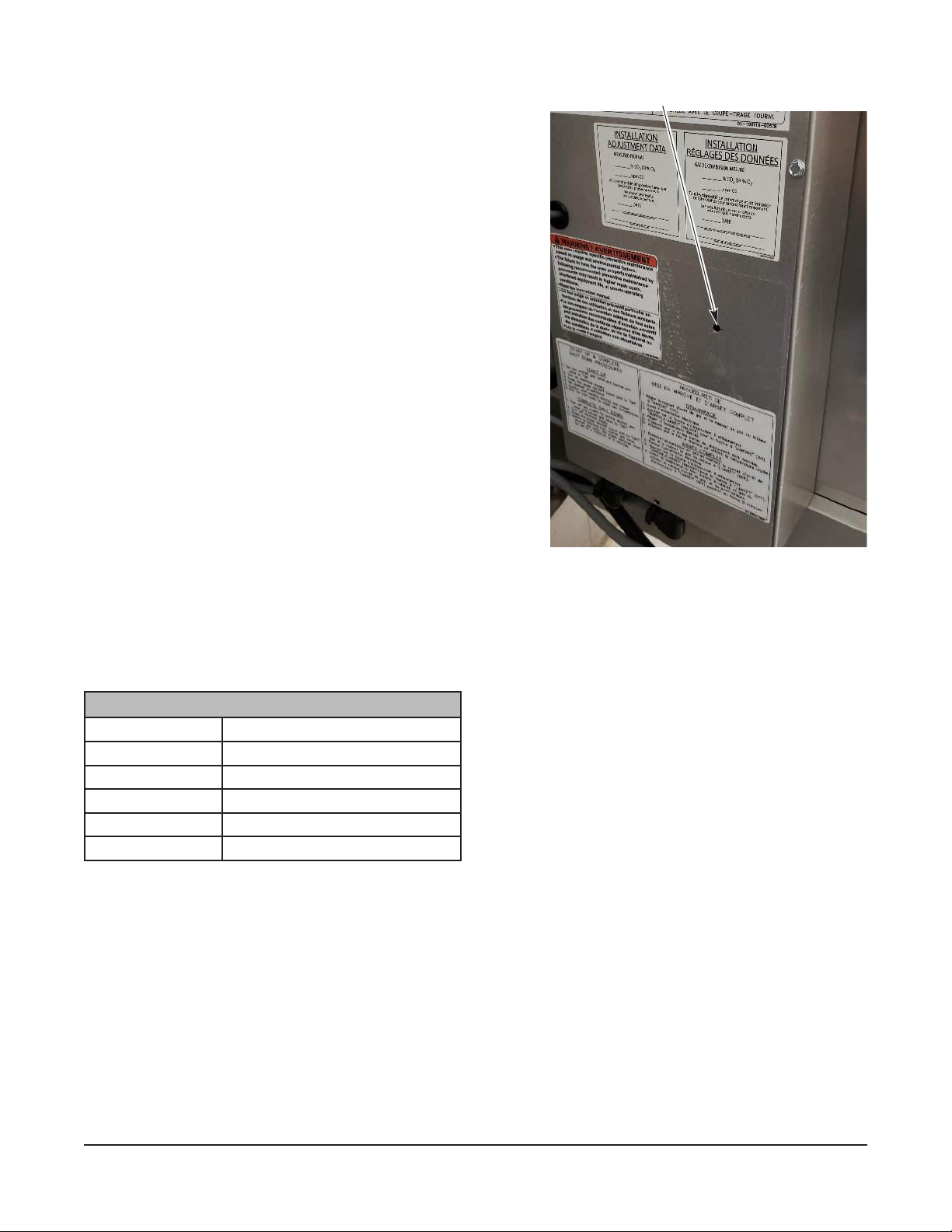
Verify Ignition Module Safety Lockout Functions (Gas Only)
1. Verify ignition module safety lockout functions.
A. Turn o main gas supply to the oven.
B. Open control panel door to gain access to burner
compartment area.
C. Turn the oven on. Check that electrical breakers
are turned on.
D. Set the oven to call for heat and make sure
convection fan is running.
E. Observe Llight-Emitting Diode (LED) light through
hole in control box cover (Fig. 65). After trying to
light the burner three times, the module should
lockout. (See chart below.)
F. Turn o the oven control for a minimum of 5
seconds and then turn the oven control back
on.
G. Turn main gas supply to the oven back on.
H. Set the oven to call for heat, making sure
convection fan is running and the burner has
established a ame.
I. Turn o main gas supply to the oven.
Observe LED through hole
Fig. 65
J. Observe LED light through hole in control box cover (Fig. 65). The ignition module should go
into lockout after three trials for ignition. (See chart below.)
K. If the proper results have been obtained, proceed to step 2; if not contact your local Baxter
authorized service oce.
LED DIAGNOSTIC INDICATOR CODES
LED LED
LED O No Fault
LED Illuminated Module Fault
‘1’ Flash Air Flow Fault
‘2’ Flash Flame Fault No Call for Heat
‘3’ Flash Ignition Module Lockout
– 34 –
Page 35
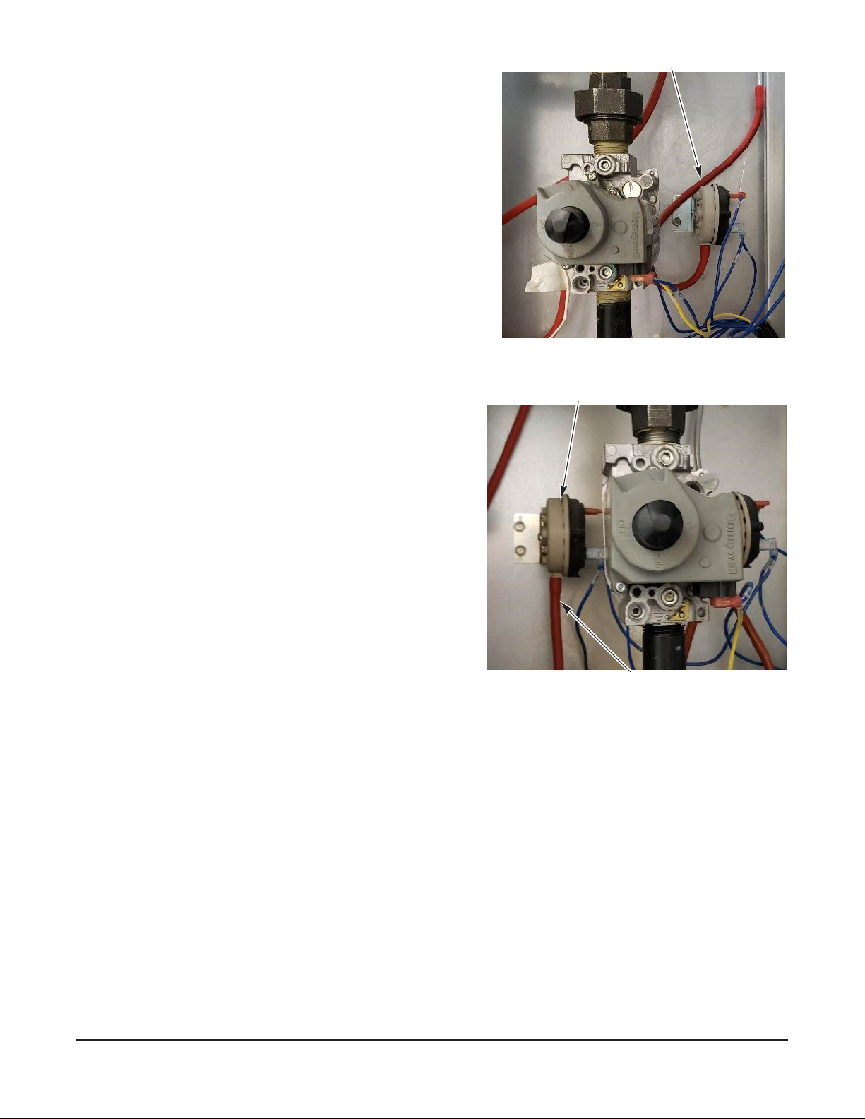
2. Verify hood exhaust air pressure switch (Fig. 66) operation.
A. Turn on main gas supply and set oven control
to call for heat and make sure convection fan is
running.
B. Once ame is established, disconnect tubing
from hood pressure switch hose. Burner ame
should go out.
C. Reconnect tubing. Burner should establish a
ame. If not, contact your local Baxter authorized
service oce.
3. Verify draft inducer pressure switch (Fig. 67) operation.
A. Set oven control to call for heat and make sure
convection fan is running.
B. Once ame is established, disconnect tubing
from draft inducer pressure switch. Burner ame
should go out.
Draft Inducer Pressure Switch
C. Reconnect tubing. Burner should establish
a ame. If not, contact your local Baxter
authorized service oce.
Disconnect Tubing
Hood Exhaust Air Pressure Switch
Fig. 66
Verify Operation of Steam
1. Check steam system for proper operation.
A. Turn the water supply on.
B. Turn oven on and set to normal bake
temperature.
C. Allow oven to preheat for 30 minutes.
D. Set control to call for steam.
E. Observe operation. If steam is not observed,
contact your local Baxter authorized service
oce.
Disconnect Tubing
Fig. 67
After completion of the owner PM procedure, you will need to contact a qualied servicer for any
needed repairs.
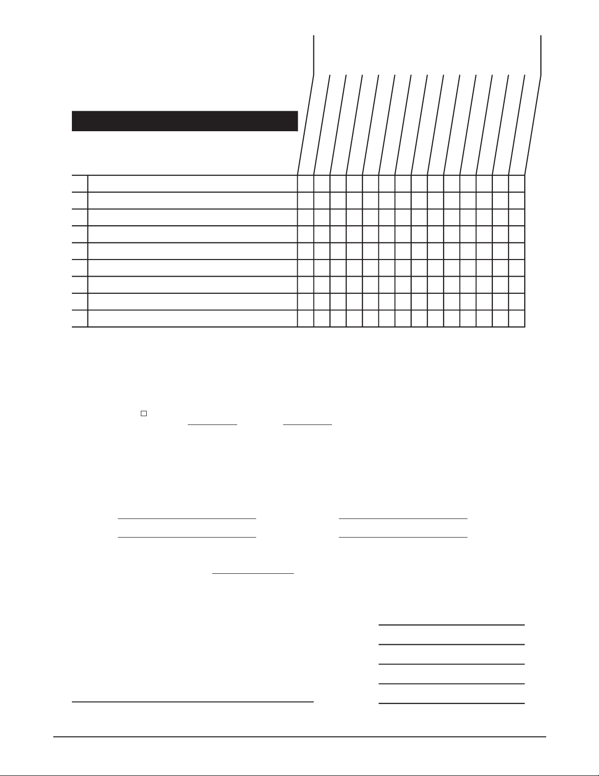
Keep a copy of the Owner Preventive Maintenance Checklist for your records.
– 35 –
Page 36
DEDEENSAYPOC
SREBMUNLAIRES/LEDOM
RENWODEDNEMMOCER
TSILKCEHCECNANETNIAMEVITNEVERP
SAG-SNEVOKCARYREKAB
.NAELCRONOITAREPOREPORPROFKCEHC
YRASSECENSAECIVRESROFLLAC
spmalnevotcepsnI
saerarenrubdnastnenopmocmuucavdnanaelC
seilbmessanoitatordnatfilkcartcepsnI
stnenopmocroodtcepsnI
srevuolriatcepsnI
tnevytivactcepsnI
snoitcennoclacirtceletcepsniyllausiV
snoitcnuftuokcolytefaseludomnoitingiyfireV
maetsfonoitarepoyfireV
=
√=
DETELPMOCSSECORP
:ycneuqerFMPylhtnom-iB
enaporPsaGlarutaNsaGfoepyT
.oNerotS:noitacoL
:detelpmoCetaD:rotcepsnI
:sriapeRyrasseceNrofdeifitoNecivreS
)etaD(
:stnemmoC
)erutangiSrotcepsnI(
FORM 36764 Rev. D (September 2022) PRINTED IN U.S.A.
– 36 –
 Loading...