

Page 1
MW-3000529-01
en
Installation and Service Manual
Reversible air/water "Split Inverter" heat pump
Platinum BC iPlus
iMPI/H 4-8
iMPI/E 4-8
iMPI/H 11-16
iMPI/E 11-16
iMPI/H 4–8 insulated
iMPI/E 4-8 insulated
iMPI/H 11–16 insulated
iMPI/E 11-16 insulated
Page 2

Contents
1 Safety instructions and recommendations . . . . . . . . . . . . . . . . . . . . . . . . . . . . . . . . . . . . . . . . . . . . . . . . . . . . . . . . . . . . . . . . 5
1.1 Safety . . . . . . . . . . . . . . . . . . . . . . . . . . . . . . . . . . . . . . . . . . . . . . . . . . . . . . . . . . . . . . . . . . . . . . . . . . . . . . . . . . . . . . . 5
1.2 General instructions . . . . . . . . . . . . . . . . . . . . . . . . . . . . . . . . . . . . . . . . . . . . . . . . . . . . . . . . . . . . . . . . . . . . . . . . . . . . 6
1.3 Electrical safety . . . . . . . . . . . . . . . . . . . . . . . . . . . . . . . . . . . . . . . . . . . . . . . . . . . . . . . . . . . . . . . . . . . . . . . . . . . . . . . .6
1.4 Refrigerant safety . . . . . . . . . . . . . . . . . . . . . . . . . . . . . . . . . . . . . . . . . . . . . . . . . . . . . . . . . . . . . . . . . . . . . . . . . . . . . . 7
1.5 Domestic water safety . . . . . . . . . . . . . . . . . . . . . . . . . . . . . . . . . . . . . . . . . . . . . . . . . . . . . . . . . . . . . . . . . . . . . . . . . . .7
1.6 Hydraulic safety . . . . . . . . . . . . . . . . . . . . . . . . . . . . . . . . . . . . . . . . . . . . . . . . . . . . . . . . . . . . . . . . . . . . . . . . . . . . . . . .8
1.7 Recommendations for the installation . . . . . . . . . . . . . . . . . . . . . . . . . . . . . . . . . . . . . . . . . . . . . . . . . . . . . . . . . . . . . . .8
1.8 Specific instructions for service, maintenance and breakdowns . . . . . . . . . . . . . . . . . . . . . . . . . . . . . . . . . . . . . . . . . . .8
1.9 Liabilities . . . . . . . . . . . . . . . . . . . . . . . . . . . . . . . . . . . . . . . . . . . . . . . . . . . . . . . . . . . . . . . . . . . . . . . . . . . . . . . . . . . . . 9
2 About this manual . . . . . . . . . . . . . . . . . . . . . . . . . . . . . . . . . . . . . . . . . . . . . . . . . . . . . . . . . . . . . . . . . . . . . . . . . . . . . . . . . . 10
2.1 Additional documentation . . . . . . . . . . . . . . . . . . . . . . . . . . . . . . . . . . . . . . . . . . . . . . . . . . . . . . . . . . . . . . . . . . . . . . . 10
2.2 Symbols used . . . . . . . . . . . . . . . . . . . . . . . . . . . . . . . . . . . . . . . . . . . . . . . . . . . . . . . . . . . . . . . . . . . . . . . . . . . . . . . . 10
2.2.1 Symbols used in the manual . . . . . . . . . . . . . . . . . . . . . . . . . . . . . . . . . . . . . . . . . . . . . . . . . . . . . . . . . . . . . 10
2.2.2 Symbols used on the appliance . . . . . . . . . . . . . . . . . . . . . . . . . . . . . . . . . . . . . . . . . . . . . . . . . . . . . . . . . . .10
3 Technical specifications . . . . . . . . . . . . . . . . . . . . . . . . . . . . . . . . . . . . . . . . . . . . . . . . . . . . . . . . . . . . . . . . . . . . . . . . . . . . . 12
3.1 Homologations . . . . . . . . . . . . . . . . . . . . . . . . . . . . . . . . . . . . . . . . . . . . . . . . . . . . . . . . . . . . . . . . . . . . . . . . . . . . . . . 12
3.1.1 Directives . . . . . . . . . . . . . . . . . . . . . . . . . . . . . . . . . . . . . . . . . . . . . . . . . . . . . . . . . . . . . . . . . . . . . . . . . . . .12
3.1.2 Factory test . . . . . . . . . . . . . . . . . . . . . . . . . . . . . . . . . . . . . . . . . . . . . . . . . . . . . . . . . . . . . . . . . . . . . . . . . . 12
3.2 Technical data . . . . . . . . . . . . . . . . . . . . . . . . . . . . . . . . . . . . . . . . . . . . . . . . . . . . . . . . . . . . . . . . . . . . . . . . . . . . . . . .12
3.2.1 Heat pump . . . . . . . . . . . . . . . . . . . . . . . . . . . . . . . . . . . . . . . . . . . . . . . . . . . . . . . . . . . . . . . . . . . . . . . . . . . 12
3.2.2 Heat pump weight . . . . . . . . . . . . . . . . . . . . . . . . . . . . . . . . . . . . . . . . . . . . . . . . . . . . . . . . . . . . . . . . . . . . . 14
3.2.3 Combination heaters with medium-temperature heat pump . . . . . . . . . . . . . . . . . . . . . . . . . . . . . . . . . . . . . 14
3.2.4 Sensor specifications . . . . . . . . . . . . . . . . . . . . . . . . . . . . . . . . . . . . . . . . . . . . . . . . . . . . . . . . . . . . . . . . . . .18
3.2.5 Circulating pump . . . . . . . . . . . . . . . . . . . . . . . . . . . . . . . . . . . . . . . . . . . . . . . . . . . . . . . . . . . . . . . . . . . . . . 18
3.3 Dimensions and connections . . . . . . . . . . . . . . . . . . . . . . . . . . . . . . . . . . . . . . . . . . . . . . . . . . . . . . . . . . . . . . . . . . . . 19
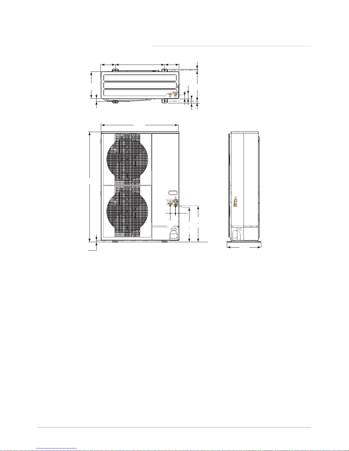
3.3.1 AWHP 4.5 MR . . . . . . . . . . . . . . . . . . . . . . . . . . . . . . . . . . . . . . . . . . . . . . . . . . . . . . . . . . . . . . . . . . . . . . . . 19
3.3.2 AWHP 6 MR-3 . . . . . . . . . . . . . . . . . . . . . . . . . . . . . . . . . . . . . . . . . . . . . . . . . . . . . . . . . . . . . . . . . . . . . . . . 19
3.3.3 AWHP 8 MR-2 . . . . . . . . . . . . . . . . . . . . . . . . . . . . . . . . . . . . . . . . . . . . . . . . . . . . . . . . . . . . . . . . . . . . . . . . 20
3.3.4 AWHP 11 MR-2 – AWHP 16 MR-2 – AWHP 11 TR-2 – AWHP 16 TR-2 . . . . . . . . . . . . . . . . . . . . . . . . . . . .21
3.3.5 iMPI with hydraulic back-up . . . . . . . . . . . . . . . . . . . . . . . . . . . . . . . . . . . . . . . . . . . . . . . . . . . . . . . . . . . . . .22
3.3.6 iMPI with electrical back-up . . . . . . . . . . . . . . . . . . . . . . . . . . . . . . . . . . . . . . . . . . . . . . . . . . . . . . . . . . . . . . 23
3.4 Electrical diagram . . . . . . . . . . . . . . . . . . . . . . . . . . . . . . . . . . . . . . . . . . . . . . . . . . . . . . . . . . . . . . . . . . . . . . . . . . . . . 24
4 Description of the product . . . . . . . . . . . . . . . . . . . . . . . . . . . . . . . . . . . . . . . . . . . . . . . . . . . . . . . . . . . . . . . . . . . . . . . . . . . . 26
4.1 Operating principle . . . . . . . . . . . . . . . . . . . . . . . . . . . . . . . . . . . . . . . . . . . . . . . . . . . . . . . . . . . . . . . . . . . . . . . . . . . . 26
4.2 Main components . . . . . . . . . . . . . . . . . . . . . . . . . . . . . . . . . . . . . . . . . . . . . . . . . . . . . . . . . . . . . . . . . . . . . . . . . . . . . 26
4.3 Standard delivery . . . . . . . . . . . . . . . . . . . . . . . . . . . . . . . . . . . . . . . . . . . . . . . . . . . . . . . . . . . . . . . . . . . . . . . . . . . . . 27
5 Before installation . . . . . . . . . . . . . . . . . . . . . . . . . . . . . . . . . . . . . . . . . . . . . . . . . . . . . . . . . . . . . . . . . . . . . . . . . . . . . . . . . . 28
5.1 Regulations governing installation . . . . . . . . . . . . . . . . . . . . . . . . . . . . . . . . . . . . . . . . . . . . . . . . . . . . . . . . . . . . . . . . 28
5.2 Installation requirements . . . . . . . . . . . . . . . . . . . . . . . . . . . . . . . . . . . . . . . . . . . . . . . . . . . . . . . . . . . . . . . . . . . . . . . .28
5.2.1 Treatment of the heating water . . . . . . . . . . . . . . . . . . . . . . . . . . . . . . . . . . . . . . . . . . . . . . . . . . . . . . . . . . . 28
5.2.2 Special precautions for the connection of the heating circuit . . . . . . . . . . . . . . . . . . . . . . . . . . . . . . . . . . . . .29
5.3 Choice of the location . . . . . . . . . . . . . . . . . . . . . . . . . . . . . . . . . . . . . . . . . . . . . . . . . . . . . . . . . . . . . . . . . . . . . . . . . . 29
5.3.1 Data plate . . . . . . . . . . . . . . . . . . . . . . . . . . . . . . . . . . . . . . . . . . . . . . . . . . . . . . . . . . . . . . . . . . . . . . . . . . . 29
5.3.2 Overall space needed by the indoor module . . . . . . . . . . . . . . . . . . . . . . . . . . . . . . . . . . . . . . . . . . . . . . . . . 30
5.3.3 Distance between modules . . . . . . . . . . . . . . . . . . . . . . . . . . . . . . . . . . . . . . . . . . . . . . . . . . . . . . . . . . . . . . 31
5.3.4 Installing the outdoor unit on the ground . . . . . . . . . . . . . . . . . . . . . . . . . . . . . . . . . . . . . . . . . . . . . . . . . . . . 31
5.4 Fitting the outdoor sensor . . . . . . . . . . . . . . . . . . . . . . . . . . . . . . . . . . . . . . . . . . . . . . . . . . . . . . . . . . . . . . . . . . . . . . . 34
5.4.1 Recommended positions . . . . . . . . . . . . . . . . . . . . . . . . . . . . . . . . . . . . . . . . . . . . . . . . . . . . . . . . . . . . . . . . 34
5.4.2 Positions to be avoided . . . . . . . . . . . . . . . . . . . . . . . . . . . . . . . . . . . . . . . . . . . . . . . . . . . . . . . . . . . . . . . . . 34
6 Connecting diagrams . . . . . . . . . . . . . . . . . . . . . . . . . . . . . . . . . . . . . . . . . . . . . . . . . . . . . . . . . . . . . . . . . . . . . . . . . . . . . . . 36
6.1 Connection for the iMPI heat pump with electrical back-up with a domestic hot water tank and an underfloor heating
circuit . . . . . . . . . . . . . . . . . . . . . . . . . . . . . . . . . . . . . . . . . . . . . . . . . . . . . . . . . . . . . . . . . . . . . . . . . . . . . . . . . . . . . . . . . . . .36
6.1.1 Connect and configure the iMPI heat pump with electrical back-up with a domestic hot water tank and a
direct circuit . . . . . . . . . . . . . . . . . . . . . . . . . . . . . . . . . . . . . . . . . . . . . . . . . . . . . . . . . . . . . . . . . . . . . . . . . . . . . . . . . .37
6.2 Connection for the iMPI heat pump with electrical back-up with 2 circuits and a buffer tank . . . . . . . . . . . . . . . . . . . . 38
6.2.1 Connect and configure the iMPI heat pump with electrical back-up with 2 circuits and a buffer tank . . . . . . 39
6.3 Connection for the iMPI heat pump with electrical back-up with 2 circuits with a low-loss header . . . . . . . . . . . . . . . .40
Contents
2 AWHP-2 iMPI 7685645 - v04 - 07032018
Page 3

6.3.1 Connect and configure the iMPI heat pump with electrical back-up with a direct circuit, a circuit with mixing
valve, a low-loss header and two TXM connected thermostats . . . . . . . . . . . . . . . . . . . . . . . . . . . . . . . . . . . . . . . . . . 41
6.4 Connection for the iMPI heat pump with hydraulic back-up with a direct circuit . . . . . . . . . . . . . . . . . . . . . . . . . . . . . . 42
6.4.1 Connect and configure the iMPI heat pump with hydraulic back-up with a direct circuit . . . . . . . . . . . . . . . . 42
7 Installation . . . . . . . . . . . . . . . . . . . . . . . . . . . . . . . . . . . . . . . . . . . . . . . . . . . . . . . . . . . . . . . . . . . . . . . . . . . . . . . . . . . . . . . . 44
7.1 General . . . . . . . . . . . . . . . . . . . . . . . . . . . . . . . . . . . . . . . . . . . . . . . . . . . . . . . . . . . . . . . . . . . . . . . . . . . . . . . . . . . . . 44
7.2 Preparation . . . . . . . . . . . . . . . . . . . . . . . . . . . . . . . . . . . . . . . . . . . . . . . . . . . . . . . . . . . . . . . . . . . . . . . . . . . . . . . . . . 44
7.2.1 Mounting the indoor module . . . . . . . . . . . . . . . . . . . . . . . . . . . . . . . . . . . . . . . . . . . . . . . . . . . . . . . . . . . . . 44
7.3 Hydraulic connections . . . . . . . . . . . . . . . . . . . . . . . . . . . . . . . . . . . . . . . . . . . . . . . . . . . . . . . . . . . . . . . . . . . . . . . . . .45
7.3.1 Connecting the heating circuit . . . . . . . . . . . . . . . . . . . . . . . . . . . . . . . . . . . . . . . . . . . . . . . . . . . . . . . . . . . . 45
7.3.2 Connecting the safety valve drain pipe . . . . . . . . . . . . . . . . . . . . . . . . . . . . . . . . . . . . . . . . . . . . . . . . . . . . . 46
7.4 Refrigeration connections . . . . . . . . . . . . . . . . . . . . . . . . . . . . . . . . . . . . . . . . . . . . . . . . . . . . . . . . . . . . . . . . . . . . . . . 46
7.4.1 Installing the refrigeration link . . . . . . . . . . . . . . . . . . . . . . . . . . . . . . . . . . . . . . . . . . . . . . . . . . . . . . . . . . . . 46
7.4.2 Connecting the refrigeration link . . . . . . . . . . . . . . . . . . . . . . . . . . . . . . . . . . . . . . . . . . . . . . . . . . . . . . . . . . 47
7.4.3 Test the tightness . . . . . . . . . . . . . . . . . . . . . . . . . . . . . . . . . . . . . . . . . . . . . . . . . . . . . . . . . . . . . . . . . . . . . 50
7.4.4 Evacuation . . . . . . . . . . . . . . . . . . . . . . . . . . . . . . . . . . . . . . . . . . . . . . . . . . . . . . . . . . . . . . . . . . . . . . . . . . .51
7.4.5 Opening the valves . . . . . . . . . . . . . . . . . . . . . . . . . . . . . . . . . . . . . . . . . . . . . . . . . . . . . . . . . . . . . . . . . . . . 51
7.5 Electrical connections . . . . . . . . . . . . . . . . . . . . . . . . . . . . . . . . . . . . . . . . . . . . . . . . . . . . . . . . . . . . . . . . . . . . . . . . . . 51
7.5.1 Recommendations . . . . . . . . . . . . . . . . . . . . . . . . . . . . . . . . . . . . . . . . . . . . . . . . . . . . . . . . . . . . . . . . . . . . .51
7.5.2 Routing the cables . . . . . . . . . . . . . . . . . . . . . . . . . . . . . . . . . . . . . . . . . . . . . . . . . . . . . . . . . . . . . . . . . . . . .52
7.5.3 Description of the connection terminal blocks . . . . . . . . . . . . . . . . . . . . . . . . . . . . . . . . . . . . . . . . . . . . . . . . 53
7.5.4 Recommended cable cross section . . . . . . . . . . . . . . . . . . . . . . . . . . . . . . . . . . . . . . . . . . . . . . . . . . . . . . . .53
7.5.5 Accessing the PCBs and connection terminal block . . . . . . . . . . . . . . . . . . . . . . . . . . . . . . . . . . . . . . . . . . . 54
7.5.6 Electrically connecting the outdoor unit . . . . . . . . . . . . . . . . . . . . . . . . . . . . . . . . . . . . . . . . . . . . . . . . . . . . . 56
7.5.7 Connecting the outdoor unit bus . . . . . . . . . . . . . . . . . . . . . . . . . . . . . . . . . . . . . . . . . . . . . . . . . . . . . . . . . . 58
7.5.8 Connecting the outside sensor . . . . . . . . . . . . . . . . . . . . . . . . . . . . . . . . . . . . . . . . . . . . . . . . . . . . . . . . . . . 58
7.5.9 Connecting the hydraulic back-up. . . . . . . . . . . . . . . . . . . . . . . . . . . . . . . . . . . . . . . . . . . . . . . . . . . . . . . . . 58
7.5.10 Connecting the power supply for the electrical back-up . . . . . . . . . . . . . . . . . . . . . . . . . . . . . . . . . . . . . . . . 59
7.5.11 Connecting a swimming pool . . . . . . . . . . . . . . . . . . . . . . . . . . . . . . . . . . . . . . . . . . . . . . . . . . . . . . . . . . . . .62
7.6 Connecting the options . . . . . . . . . . . . . . . . . . . . . . . . . . . . . . . . . . . . . . . . . . . . . . . . . . . . . . . . . . . . . . . . . . . . . . . . . 63
7.6.1 Connecting an on/off or modulating thermostat . . . . . . . . . . . . . . . . . . . . . . . . . . . . . . . . . . . . . . . . . . . . . . .63
7.6.2 Connecting a thermostat with heating/cooling connector . . . . . . . . . . . . . . . . . . . . . . . . . . . . . . . . . . . . . . . 63
7.7 Filling the installation . . . . . . . . . . . . . . . . . . . . . . . . . . . . . . . . . . . . . . . . . . . . . . . . . . . . . . . . . . . . . . . . . . . . . . . . . . .64
7.7.1 Filling the heating circuit . . . . . . . . . . . . . . . . . . . . . . . . . . . . . . . . . . . . . . . . . . . . . . . . . . . . . . . . . . . . . . . . 64
8 Commissioning . . . . . . . . . . . . . . . . . . . . . . . . . . . . . . . . . . . . . . . . . . . . . . . . . . . . . . . . . . . . . . . . . . . . . . . . . . . . . . . . . . . . 65
8.1 General . . . . . . . . . . . . . . . . . . . . . . . . . . . . . . . . . . . . . . . . . . . . . . . . . . . . . . . . . . . . . . . . . . . . . . . . . . . . . . . . . . . . . 65
8.2 Checklist before commissioning . . . . . . . . . . . . . . . . . . . . . . . . . . . . . . . . . . . . . . . . . . . . . . . . . . . . . . . . . . . . . . . . . . 65
8.2.1 Checking the heating circuit . . . . . . . . . . . . . . . . . . . . . . . . . . . . . . . . . . . . . . . . . . . . . . . . . . . . . . . . . . . . . .65
8.2.2 Checking the electrical connections . . . . . . . . . . . . . . . . . . . . . . . . . . . . . . . . . . . . . . . . . . . . . . . . . . . . . . . 65
8.2.3 Checking the refrigeration circuit . . . . . . . . . . . . . . . . . . . . . . . . . . . . . . . . . . . . . . . . . . . . . . . . . . . . . . . . . . 65
8.3 Commissioning procedure . . . . . . . . . . . . . . . . . . . . . . . . . . . . . . . . . . . . . . . . . . . . . . . . . . . . . . . . . . . . . . . . . . . . . . 65
8.3.1 CNF menu . . . . . . . . . . . . . . . . . . . . . . . . . . . . . . . . . . . . . . . . . . . . . . . . . . . . . . . . . . . . . . . . . . . . . . . . . . . 66
8.3.2 Start-up cycle . . . . . . . . . . . . . . . . . . . . . . . . . . . . . . . . . . . . . . . . . . . . . . . . . . . . . . . . . . . . . . . . . . . . . . . . .66
8.4 Using the installation wizard on the control panel . . . . . . . . . . . . . . . . . . . . . . . . . . . . . . . . . . . . . . . . . . . . . . . . . . . . .67
8.5 Checking the minimum flow . . . . . . . . . . . . . . . . . . . . . . . . . . . . . . . . . . . . . . . . . . . . . . . . . . . . . . . . . . . . . . . . . . . . . 68
8.6 Final instructions . . . . . . . . . . . . . . . . . . . . . . . . . . . . . . . . . . . . . . . . . . . . . . . . . . . . . . . . . . . . . . . . . . . . . . . . . . . . . . 68
9 Operation . . . . . . . . . . . . . . . . . . . . . . . . . . . . . . . . . . . . . . . . . . . . . . . . . . . . . . . . . . . . . . . . . . . . . . . . . . . . . . . . . . . . . . . . .70
9.1 Use of the control panel . . . . . . . . . . . . . . . . . . . . . . . . . . . . . . . . . . . . . . . . . . . . . . . . . . . . . . . . . . . . . . . . . . . . . . . . 70
9.1.1 Control panel description . . . . . . . . . . . . . . . . . . . . . . . . . . . . . . . . . . . . . . . . . . . . . . . . . . . . . . . . . . . . . . . .70
9.1.2 Browsing in the menus . . . . . . . . . . . . . . . . . . . . . . . . . . . . . . . . . . . . . . . . . . . . . . . . . . . . . . . . . . . . . . . . . 72
9.1.3 Description of the PCBs . . . . . . . . . . . . . . . . . . . . . . . . . . . . . . . . . . . . . . . . . . . . . . . . . . . . . . . . . . . . . . . . .73
9.2 Start-up . . . . . . . . . . . . . . . . . . . . . . . . . . . . . . . . . . . . . . . . . . . . . . . . . . . . . . . . . . . . . . . . . . . . . . . . . . . . . . . . . . . . . 73
9.3 Shutdown . . . . . . . . . . . . . . . . . . . . . . . . . . . . . . . . . . . . . . . . . . . . . . . . . . . . . . . . . . . . . . . . . . . . . . . . . . . . . . . . . . . 73
9.3.1 Switching off the heating . . . . . . . . . . . . . . . . . . . . . . . . . . . . . . . . . . . . . . . . . . . . . . . . . . . . . . . . . . . . . . . . 73
9.3.2 Shutting down the cooling function . . . . . . . . . . . . . . . . . . . . . . . . . . . . . . . . . . . . . . . . . . . . . . . . . . . . . . . . 74
9.4 Frost Protection . . . . . . . . . . . . . . . . . . . . . . . . . . . . . . . . . . . . . . . . . . . . . . . . . . . . . . . . . . . . . . . . . . . . . . . . . . . . . . .74
10 Settings . . . . . . . . . . . . . . . . . . . . . . . . . . . . . . . . . . . . . . . . . . . . . . . . . . . . . . . . . . . . . . . . . . . . . . . . . . . . . . . . . . . . . . . . . . 76
10.1 Modifying the installer parameters . . . . . . . . . . . . . . . . . . . . . . . . . . . . . . . . . . . . . . . . . . . . . . . . . . . . . . . . . . . . . . 76
10.2 Installer menu . . . . . . . . . . . . . . . . . . . . . . . . . . . . . . . . . . . . . . . . . . . . . . . . . . . . . . . . . . . . . . . . . . . . . . . . . . . . . . 76
10.2.1 Installer \CIRCA and CIRCB menu . . . . . . . . . . . . . . . . . . . . . . . . . . . . . . . . . . . . . . . . . . . . . . . . . . . . . . .77
10.2.2 Installer \CIRCA and CIRCB\ADV menu . . . . . . . . . . . . . . . . . . . . . . . . . . . . . . . . . . . . . . . . . . . . . . . . . . 78
Contents
7685645 - v04 - 07032018 AWHP-2 iMPI 3
Page 4

10.2.3 Installer \DHW menu . . . . . . . . . . . . . . . . . . . . . . . . . . . . . . . . . . . . . . . . . . . . . . . . . . . . . . . . . . . . . . . . . .79
10.2.4 Installer \DHW\ADV menu . . . . . . . . . . . . . . . . . . . . . . . . . . . . . . . . . . . . . . . . . . . . . . . . . . . . . . . . . . . . . 79
10.2.5 Installer \EHC–04 and SCB-04 menu . . . . . . . . . . . . . . . . . . . . . . . . . . . . . . . . . . . . . . . . . . . . . . . . . . . . . 80
10.2.6 Installer \EHC–04 and SCB-04\ADV menu . . . . . . . . . . . . . . . . . . . . . . . . . . . . . . . . . . . . . . . . . . . . . . . . .82
10.3 COUNTERS /TIME PROG / CLOCK menus . . . . . . . . . . . . . . . . . . . . . . . . . . . . . . . . . . . . . . . . . . . . . . . . . . . . . . 85
10.3.1 COUNTERS, TIME PROG, CLOCK \CNT menus . . . . . . . . . . . . . . . . . . . . . . . . . . . . . . . . . . . . . . . . . . . 85
10.3.2 COUNTERS, TIME PROG, CLOCK \CIRCA, CIRCB and DHW menus . . . . . . . . . . . . . . . . . . . . . . . . . . 86
10.3.3 COUNTERS, TIME PROG, CLOCK \CLK menus . . . . . . . . . . . . . . . . . . . . . . . . . . . . . . . . . . . . . . . . . . . 87
10.4 Description of the parameters . . . . . . . . . . . . . . . . . . . . . . . . . . . . . . . . . . . . . . . . . . . . . . . . . . . . . . . . . . . . . . . . . . . .87
10.4.1 Running the back-up in heating mode . . . . . . . . . . . . . . . . . . . . . . . . . . . . . . . . . . . . . . . . . . . . . . . . . . . . . . 87
10.4.2 Setting the switch between heating and production of domestic hot water . . . . . . . . . . . . . . . . . . . . . . . . . . 88
10.4.3 Running the back-up in domestic hot water mode . . . . . . . . . . . . . . . . . . . . . . . . . . . . . . . . . . . . . . . . . . . . .89
10.5 Setting the parameters . . . . . . . . . . . . . . . . . . . . . . . . . . . . . . . . . . . . . . . . . . . . . . . . . . . . . . . . . . . . . . . . . . . . . . . . . 89
10.5.1 Language selection . . . . . . . . . . . . . . . . . . . . . . . . . . . . . . . . . . . . . . . . . . . . . . . . . . . . . . . . . . . . . . . . . . . . 89
10.5.2 Selecting the type of outdoor unit and the type of back-up (CN1 et CN2) . . . . . . . . . . . . . . . . . . . . . . . . . . .90
10.5.3 Setting the heating curve . . . . . . . . . . . . . . . . . . . . . . . . . . . . . . . . . . . . . . . . . . . . . . . . . . . . . . . . . . . . . . . . 91
10.5.4 Configuring the estimated electrical energy consumption function . . . . . . . . . . . . . . . . . . . . . . . . . . . . . . . . 91
10.5.5 Configuring a hydraulic back-up . . . . . . . . . . . . . . . . . . . . . . . . . . . . . . . . . . . . . . . . . . . . . . . . . . . . . . . . . . 92
10.5.6 Configuring the hybrid operating mode of a hydraulic back-up . . . . . . . . . . . . . . . . . . . . . . . . . . . . . . . . . . . 93
10.5.7 Configuring a convection fan or underfloor cooling . . . . . . . . . . . . . . . . . . . . . . . . . . . . . . . . . . . . . . . . . . . . 94
10.5.8 Screed drying with the aid of the heat pump . . . . . . . . . . . . . . . . . . . . . . . . . . . . . . . . . . . . . . . . . . . . . . . . . 95
10.5.9 Drying screed without the heat pump outdoor unit. . . . . . . . . . . . . . . . . . . . . . . . . . . . . . . . . . . . . . . . . . . . . 96
10.5.10 Supplying the heat pump with photovoltaic energy . . . . . . . . . . . . . . . . . . . . . . . . . . . . . . . . . . . . . . . . . . . . 96
10.5.11 Connecting the installation to a Smart Grid . . . . . . . . . . . . . . . . . . . . . . . . . . . . . . . . . . . . . . . . . . . . . . . . . . 96
10.5.12 Reducing the noise level of the outdoor unit . . . . . . . . . . . . . . . . . . . . . . . . . . . . . . . . . . . . . . . . . . . . . . . . . 97
10.5.13 Detecting an additional or replacement PCB . . . . . . . . . . . . . . . . . . . . . . . . . . . . . . . . . . . . . . . . . . . . . . . . .97
10.6 Reading out measured values . . . . . . . . . . . . . . . . . . . . . . . . . . . . . . . . . . . . . . . . . . . . . . . . . . . . . . . . . . . . . . . . . 98
10.6.1 Control system sequence . . . . . . . . . . . . . . . . . . . . . . . . . . . . . . . . . . . . . . . . . . . . . . . . . . . . . . . . . . . . . . 100
11 Maintenance . . . . . . . . . . . . . . . . . . . . . . . . . . . . . . . . . . . . . . . . . . . . . . . . . . . . . . . . . . . . . . . . . . . . . . . . . . . . . . . . . . . . . 104
11.1 General . . . . . . . . . . . . . . . . . . . . . . . . . . . . . . . . . . . . . . . . . . . . . . . . . . . . . . . . . . . . . . . . . . . . . . . . . . . . . . . . . . . . 104
11.2 Checking operation of the appliance . . . . . . . . . . . . . . . . . . . . . . . . . . . . . . . . . . . . . . . . . . . . . . . . . . . . . . . . . . . . . .104
11.3 Standard inspection and maintenance operations . . . . . . . . . . . . . . . . . . . . . . . . . . . . . . . . . . . . . . . . . . . . . . . . . . . 104
11.3.1 Checking the safety devices . . . . . . . . . . . . . . . . . . . . . . . . . . . . . . . . . . . . . . . . . . . . . . . . . . . . . . . . . . . . 105
11.3.2 Check the hydraulic pressure . . . . . . . . . . . . . . . . . . . . . . . . . . . . . . . . . . . . . . . . . . . . . . . . . . . . . . . . . . . 105
11.3.3 Cleaning the casing . . . . . . . . . . . . . . . . . . . . . . . . . . . . . . . . . . . . . . . . . . . . . . . . . . . . . . . . . . . . . . . . . . . 105
11.3.4 Draining the heating circuit . . . . . . . . . . . . . . . . . . . . . . . . . . . . . . . . . . . . . . . . . . . . . . . . . . . . . . . . . . . . . 105
11.4 Specific maintenance operations . . . . . . . . . . . . . . . . . . . . . . . . . . . . . . . . . . . . . . . . . . . . . . . . . . . . . . . . . . . . . . . . 105
11.4.1 Cleaning the 500 µm filters . . . . . . . . . . . . . . . . . . . . . . . . . . . . . . . . . . . . . . . . . . . . . . . . . . . . . . . . . . . . . 105
11.4.2 Replacing the battery in the control panel . . . . . . . . . . . . . . . . . . . . . . . . . . . . . . . . . . . . . . . . . . . . . . . . . . 106
12 Troubleshooting . . . . . . . . . . . . . . . . . . . . . . . . . . . . . . . . . . . . . . . . . . . . . . . . . . . . . . . . . . . . . . . . . . . . . . . . . . . . . . . . . . .107
12.1 Resetting the safety thermostat . . . . . . . . . . . . . . . . . . . . . . . . . . . . . . . . . . . . . . . . . . . . . . . . . . . . . . . . . . . . . . . . . 107
12.2 Error messages . . . . . . . . . . . . . . . . . . . . . . . . . . . . . . . . . . . . . . . . . . . . . . . . . . . . . . . . . . . . . . . . . . . . . . . . . . . . . .107
12.2.1 Error codes . . . . . . . . . . . . . . . . . . . . . . . . . . . . . . . . . . . . . . . . . . . . . . . . . . . . . . . . . . . . . . . . . . . . . . . . . 107
12.2.2 Fault codes . . . . . . . . . . . . . . . . . . . . . . . . . . . . . . . . . . . . . . . . . . . . . . . . . . . . . . . . . . . . . . . . . . . . . . . . . 110
12.2.3 Alarm codes . . . . . . . . . . . . . . . . . . . . . . . . . . . . . . . . . . . . . . . . . . . . . . . . . . . . . . . . . . . . . . . . . . . . . . . . .111
12.3 Accessing the error memory . . . . . . . . . . . . . . . . . . . . . . . . . . . . . . . . . . . . . . . . . . . . . . . . . . . . . . . . . . . . . . . . . 111
13 Decommissioning and disposal . . . . . . . . . . . . . . . . . . . . . . . . . . . . . . . . . . . . . . . . . . . . . . . . . . . . . . . . . . . . . . . . . . . . . . .113
13.1 Decommissioning procedure . . . . . . . . . . . . . . . . . . . . . . . . . . . . . . . . . . . . . . . . . . . . . . . . . . . . . . . . . . . . . . . . . . . .113
13.2 Disposal and Recycling . . . . . . . . . . . . . . . . . . . . . . . . . . . . . . . . . . . . . . . . . . . . . . . . . . . . . . . . . . . . . . . . . . . . . . . .113
Contents
4 AWHP-2 iMPI 7685645 - v04 - 07032018
Page 5

1 Safety instructions and recommendations
1.1 Safety
Operation
Danger
This appliance can be used by children aged from 8 years
and above and persons with reduced physical, sensory or
mental capabilities or lack of experience and knowledge if
they have been given supervision or instruction concerning
use of the appliance in a safe way and understand the haz
ards involved. Children shall not play with the appliance.
Cleaning and user maintenance shall not be made by children
without supervision.
Electrical
The appliance is intended to be permanently connected to the domestic water
mains network.
Before any work on the appliance, carefully read all documents that accompa
ny the product. These documents are also available on our website. See the
last page.
Install the appliance in accordance with national rules on electrical installation.
A disconnection device must be fitted to the permanent pipes in accordance
with installation rules.
If a power supply cable comes with the appliance and it turns out to be dam
aged, it must be replaced by the manufacturer, its after sales service or per
sons with similar qualifications in order to obviate any danger.
If the appliance is not wired in the factory, carry out the wiring according to the
wiring diagram described in the chapter Electrical Connections. See the Instal
lation and Service Manual.
This appliance must be connected to the protective earth.
Earthing must comply with the prevailing installation standards.
Earth the appliance before making any electrical connections.
Type and calibre of the protective equipment: refer to the chapter Recommen
ded cable cross-sections. See the Installation and Service Manual.
To connect the appliance to the electricity mains, refer to the chapter Electrical
Connections. See the Installation and Service Manual.
In order to prevent any danger owing to the unexpected reset of the thermal
circuit breaker, this appliance must not be powered through an external switch,
such as a timer, or be connected to a circuit which is regularly switched on and
off by the electricity provider.
1 Safety instructions and recommendations
7685645 - v04 - 07032018 AWHP-2 iMPI 5
Page 6
Domestic wa
ter
Draining the appliance:
1. Shut off the domestic cold water inlet.
2. Open a hot water tap in the installation.
3. Open a valve on the safety unit.
4. When the water stops flowing, the appliance has been drained.
The pressure limiter device (safety valve or safety unit) must be regularly oper
ated in order to remove limescale deposits and ensure that it is not blocked.
A pressure limiter device must be fitted to a discharge pipe.
As water may flow out of the discharge pipe, the pipe must be kept open to the
open air, in a frost-free environment, and at a continuous downward gradient.
To ascertain the type or specifications of the pressure limiter and to find out
how to connect it, refer to the chapter Connecting the domestic hot water tank
to the drinking water mains. See the Installation and Service Manual.
Hydraulics
Caution
Respect the minimum and maximum water pressure and tem
perature to ensure the appliance operates correctly. See
chapter on Technical Specifications.
Installation
Important
Allow the space required to install the appliance correctly, re
ferring to the chapter Dimensions of the Appliance. See the
Installation and Service Manual.
1.2
General instructions
The system must satisfy each point in the rules in force in the country that
govern works and interventions in individual homes, blocks of flats or other
buildings.
Only qualified professionals are authorised to work on the appliance and
the heating installation. They must respect prevailing local and national
regulations during fitting, installation and maintenance of the installation.
Commissioning must be performed by a qualified professional.
1.3 Electrical safety
Before making any electrical connections, earth the appliance in accord
ance with prevailing standards.
Danger
Danger of electric shock: the length of the conductors between the
traction arrester device and the terminal blocks must be such that
the active conductors are put under tension before the earth con
ductor.
Only qualified professionals may carry out electrical connections, always
with the power off.
Separate the very low voltage cables from the 230/400 V circuit cables.
1 Safety instructions and recommendations
6 AWHP-2 iMPI 7685645 - v04 - 07032018
Page 7

1.4 Refrigerant safety
Warning
Refrigerant fluid and pipes:
Use only R410A refrigerant fluid to fill the installation.
Use tools and pipe components especially designed for use with
R410A refrigerant fluid.
Use copper pipes deoxidised with phosphorus to carry the re
frigerant fluid.
Store the refrigerant connection pipes away from dust and hu
midity (risk of damage to the compressor).
Do not use a load cylinder.
Protect the heat pump components, including the insulation and
structural elements. Do not overheat the pipes as brazed com
ponents may cause damage.
Contact between the refrigerant fluid and a flame may result in
emissions of toxic gases.
France: Pursuant to Article L. 113-3 of the French Consumer Code, the in
stallation of equipment must be done by a certified operator whenever the
refrigerant load is in excess of two kilograms or when a refrigerant connec
tion is necessary (the case with split systems, even when fitted with a
quick coupling device).
All work on the refrigeration circuit must be done by a qualified professio
nal, according to prevailing codes of practice and safety in the profession
(recovery of the refrigerant, brazing under nitrogen). All brazing work must
be done by qualified welders.
Do not touch the refrigeration connection pipes with your bare hands while
the heat pump is running. Danger of burn or frost injury.
In the event of a refrigerant leakage:
1. Switch off the appliance.
2. Open the windows.
3. Do not use a naked flame, do not smoke, do not operate electrical
contacts.
4. Avoid contact with the refrigerant. Danger of frost injuries.
Locate the probable leak and seal it immediately. Use only original parts to
replace a defective refrigeration component.
Use only dehydrated nitrogen for detecting leaks or for pressurised tests.
Do not allow the refrigerant fluid to escape into the atmosphere.
1.5 Domestic water safety
In accordance with safety rules, a safety valve calibrated to 0.7 MPa (7
bar) is mounted on the tank's domestic cold water inlet.
A pressure reducer (not provided) is required when the supply pressure
exceeds 80% of the safety valve or safety unit calibration and must be lo
cated upstream of the appliance.
There must be no cut-off devices between the safety valve or unit and the
domestic hot water tank.
The hydraulic installation must be capable of handling a minimum flow rate
at all times.
Heating water and domestic water must not come into contact with each
other. Domestic water must not circulate through the exchanger.
Limit temperature at the draw-off point: the maximum domestic hot water
temperature at the draw-off point is subject to special regulations in the
various countries in which the appliance is sold in order to protect the
user. These special regulations be observed when installing the appliance.
Take precautions with the domestic hot water. Depending on the heat
pump settings, the domestic hot water temperature may exceed 65°C.
1 Safety instructions and recommendations
7685645 - v04 - 07032018 AWHP-2 iMPI 7
Page 8

In order to limit the risk of being scalded, a thermostatic mixing valve must
be installed on the domestic hot water flow pipes.
1.6 Hydraulic safety
When making the hydraulic connection, it is imperative that the standards
and corresponding local directives be respected.
If radiators are connected directly to the heating circuit: install a differential
valve between the indoor module and the heating circuit.
Keep a heating circuit without thermostatic valve and or without solenoid
valve in order to avoid having all valves closed at the same time.
Fit drainage valves between the indoor module and the heating circuit.
Do not add any chemical products to the heating water without first con
sulting a water treatment specialist. For example: antifreeze, water soften
ers, products to increase or reduce the pH value, chemical additives
and/or inhibitors. These may cause faults in the heat pump and damage
the heat exchanger.
1.7
Recommendations for the installation
Install the heat pump's indoor module in a frost-free location.
Insulate the pipes to reduce heat losses to a minimum.
Apply refrigerant oil to the beaded parts to facilitate tightening and improve
the seal.
Keep this document close to the place where the appliance is installed.
Do not make any modifications to the heat pump without the written con
sent of the manufacturer.
To benefit from extended warranty cover, no modifications should be
made to the appliance.
Install the heat pump indoor module and outdoor unit on a solid, stable
structure able to bear its weight.
Do not install the heat pump in a place that has an atmosphere with a high
salt content.
Do not install the heat pump in a place exposed to steam and combustion
gases.
Do not install the heat pump in a place that may be covered in snow.
1.8 Specific instructions for service, maintenance and breakdowns
Maintenance work must be carried out by a qualified professional.
Only a qualified professional is authorised to set, correct or replace the
safety devices.
Before any work, switch off the mains electricity to the heat pump, the in
door unit and the hydraulic or electrical back-up if connected.
Wait for approx. 20-30 seconds for the outdoor unit capacitors to be dis
charged, and check that the lights on the outdoor unit PCBs have gone
out.
Before working on the refrigeration circuit, switch off the appliance and
wait a few minutes. Certain items of equipment such as the compressor
and the pipes can reach temperatures in excess of 100 °C and high pres
sures, which may cause serious injuries.
Locate and correct the cause of power cut before resetting the safety ther
mostat.
Only genuine spare parts may be used.
Removal and disposal of the heat pump must be carried out by a qualified
professional in accordance with prevailing local and national regulations.
Do not allow the refrigerant fluid to escape into the atmosphere.
1 Safety instructions and recommendations
8 AWHP-2 iMPI 7685645 - v04 - 07032018
Page 9

After maintenance or repair work, check the entire heating system to en
sure that there are no leaks.
Remove the casing only to perform maintenance and repair work. Put the
casing back in place after maintenance and repair work.
1.9
Liabilities
Manufacturer's liability Our products are manufactured in compliance with the requirements of the various Directives appli
cable. They are therefore delivered with the marking and any documents necessary. In the inter
ests of the quality of our products, we strive constantly to improve them. We therefore reserve the
right to modify the specifications given in this document.
Our liability as manufacturer may not be invoked in the following cases:
Failure to abide by the instructions on installing the appliance.
Failure to abide by the instructions on using the appliance.
Faulty or insufficient maintenance of the appliance.
Installer's liability The installer is responsible for the installation and initial commissioning of the appliance. The instal
ler must observe the following instructions:
Read and follow the instructions given in the manuals provided with the appliance.
Install the appliance in compliance with prevailing legislation and standards.
Carry out initial commissioning and any checks necessary.
Explain the installation to the user.
If maintenance is necessary, warn the user of the obligation to check the appliance and keep it in
good working order.
Give all the instruction manuals to the user.
1 Safety instructions and recommendations
7685645 - v04 - 07032018 AWHP-2 iMPI 9
Page 10

2 About this manual
2.1 Additional documentation
This manual contains information on the heat pump's indoor module, in
cluding the domestic hot water tank, as well as various items of informa
tion on the outdoor unit.
For additional information on the outdoor unit, refer to the manual provided
with that unit.
2.2
Symbols used
2.2.1
Symbols used in the manual
This manual uses various danger levels to draw attention to special in
structions. We do this to improve user safety, to prevent problems and to
guarantee correct operation of the appliance.
Danger
Risk of dangerous situations that may result in serious personal
injury.
Danger of electric shock
Risk of electric shock.
Warning
Risk of dangerous situations that may result in minor personal in
jury.
Caution
Risk of material damage.
Important
Please note: important information.
See
Reference to other manuals or pages in this manual.
2.2.2 Symbols used on the appliance
1 Alternating current
2 Protective earthing
3 Before installing and commissioning the appliance, carefully read
the instruction manuals provided.
4 Dispose of used products through an appropriate recovery and re
cycling structure.
5 Caution: danger of electric shock, live parts. Disconnect the mains
power prior to carrying out any work.
Fig.1 Symbols used on the appliance
1 2
MW-2000068-1
1
2
3
4
5
2 About this manual
10 AWHP-2 iMPI 7685645 - v04 - 07032018
Page 11

1 Information concerning the heat pump: refrigerant type, maximum
allowable operating pressure
2 The symbol indicates compatibility with the TXM connected ther
mostat.
3 Information on the electrical back-up: power supply and maximum
output (only for versions with electrical back-up)
4 Before installing and commissioning the appliance, carefully read
the instruction manuals provided
5 Dispose of used products in an appropriate recovery and recycling
structure
Fig.2 Symbols used on the data plate
MW-5000752-1
1
4
2
5
3
2 About this manual
7685645 - v04 - 07032018 AWHP-2 iMPI 11
Page 12

3 Technical specifications
3.1 Homologations
3.1.1 Directives
This product complies with the requirements of the following European Di
rectives and Standards:
Pressure Equipment Directive 2014/68/EU
Low Voltage Directive 2014/35/EU
Generic standard: EN 60335-1
Relevant standards: EN 60335-2-21, EN 60335-2-40
Electromagnetic Compatibility Directive 2014/30/EU
Generic standards: EN 61000-6-3, EN 61000-6-1
Relevant Standard: EN 55014
This product conforms to the requirements of European Directive
2009/125/EC on the ecodesign of energy-related products.
In addition to the legal requirements and guidelines, the supplementary
guidelines in this manual must also be followed.
Supplements or subsequent regulations and guidelines that are valid at
the time of installation shall apply to all regulations and guidelines speci
fied in this manual.
EC Declaration of Conformity
The unit complies with the standard type described in the EC declaration
of conformity. It has been manufactured and commissioned in accordance
with European directives.
The original declaration of conformity is available from the manufacturer.
3.1.2 Factory test
Before leaving the factory, each indoor module is tested on the following
items:
Tightness of the heating circuit
Electrical safety
Tightness of the refrigerant circuit
Tightness of the domestic hot water circuit
3.2 Technical data
3.2.1 Heat pump
Maximum operating pressure: 0.3 MPa (3 bar)
Tab.1 Conditions of use
AWHP 4.5 MR AWHP 6 MR-3 AWHP 8 MR-2
Limit water operating temperatures in heating mode +18 °C/+55 °C +18 °C/+60 °C +18 °C/+60 °C
Limit outdoor air operating temperatures in heating mode -15 °C/+35 °C -15 °C/+35 °C -20 °C/+35 °C
Limit water operating temperatures in cooling mode for
uninsulated models
+18 °C/+25 °C +18 °C/+25 °C +18 °C/+25 °C
Limit water operating temperatures in cooling mode for in
sulated models
+7°C / +25°C +7°C / +25°C +7°C / +25°C
Limit outdoor air operating temperatures in cooling mode +7 °C/+40 °C +7 °C/+40 °C +7 °C/+40 °C
3 Technical specifications
12 AWHP-2 iMPI 7685645 - v04 - 07032018
Page 13

Tab.2 Conditions of use
AWHP 11 MR-2
AWHP 11 TR-2
AWHP 16 MR-2
AWHP 16 TR-2
Limit water operating temperatures in heating mode +18 °C/+60 °C +18 °C/+60 °C
Limit outdoor air operating temperatures in heating mode -20 °C/+35 °C -20 °C/+35 °C
Limit water operating temperatures in cooling mode for uninsulated models +18 °C/+25 °C +18 °C/+25 °C
Limit water operating temperatures in cooling mode for insulated models +7°C / +25°C +7°C / +25°C
Limit outdoor air operating temperatures in cooling mode +7 °C/+40 °C +7 °C/+40 °C
Tab.3 Heating mode: outside air temperature +7°C, water temperature at the outlet +35°C. Performances in accordance with
EN 14511-2.
Measure
ment type
Unit AWHP 4.5 MRAWHP 6
MR-3
AWHP 8
MR-2
AWHP 11
MR-2
AWHP 11
TR-2
AWHP 16
MR-2
AWHP 16
TR-2
Heat output kW 4.60 5.79 8.26 11.39 11.39 14.65 14.65
Coefficient
of Perform
ance (COP)
5.11 4.05 4.27 4.65 4.65 4.22 4.22
Absorbed
electrical
power
kWe 0.90 1.43 1.93 2.45 2.45 3.47 3.47
Nominal wa
ter flow rate
(ΔT = 5K)
m3/hour
0.88 1.13 1.53 1.96 1.96 2.53 2.53
Tab.4 Heating mode: outside air temperature +2°C, water temperature at the outlet +35°C. Performances in accordance with
EN 14511-2.
Measure
ment type
Unit AWHP 4.5 MRAWHP 6
MR-3
AWHP 8
MR-2
AWHP 11
MR-2
AWHP 11
TR-2
AWHP 16
MR-2
AWHP 16
TR-2
Heat output kW 3.47 3.65 5.3 10.19 10.19 12.90 12.90
Coefficient
of Perform
ance (COP)
3.97 3.23 3.46 3.20 3.20 3.27 3.27
Absorbed
electrical
power
kWe 0.88 1.13 1.53 3.19 3.19 3.94 3.94
Tab.5 Cooling mode: outside air temperature +35°C, water temperature at the outlet +18°C. Performances in accordance
with EN 14511-2.
Measure
ment type
Unit AWHP 4.5 MRAWHP 6
MR-3
AWHP 8
MR-2
AWHP 11
MR-2
AWHP 11
TR-2
AWHP 16
MR-2
AWHP 16
TR-2
Cooling out
put
kW 3.80 4.69 7.90 11.16 11.16 14.46 14.46
Energy effi
ciency ratio
(EER)
4.28 4.09 3.99 4.75 4.75 3.96 3.96
Absorbed
electrical
power
kWe 0.89 1.15 2.00 2.35 2.35 3.65 3.65
3 Technical specifications
7685645 - v04 - 07032018 AWHP-2 iMPI 13
Page 14
Tab.6 Common specifications
Measure
ment type
Unit AWHP 4.5 MRAWHP 6
MR-3
AWHP 8
MR-2
AWHP 11
MR-2
AWHP 11
TR-2
AWHP 16
MR-2
AWHP 16
TR-2
Power volt
age of the
outdoor unit
V 230 230 230 230 400 230 400
Start-up
amperage
A 5 5 5 5 3 6 3
Maximal
amperage
A 12 13 19 29.5 13 29.5 13
Refrigerant
fluid R410A
kg 1.3 1.4 3.2 4.6 4.6 4.6 4.6
R410A re
frigerant
(1)
tCO2e 2.714 2.923 6.680 9.603 9.603 9.603 9.603
Refrigerant
connection
(Liquid Gas)
inch 1/4 - 1/2 1/4 - 1/2 3/8 - 5/8 3/8 - 5/8 3/8 - 5/8 3/8 - 5/8 3/8 - 5/8
Max. precharged
length
m 7 10 10 10 10 10 10
(1) The quantity of refrigerant in CO2 equivalent is calculated using the following formula: quantity (in kg) of refrigerant x GWP / 1000. The
Global-Warming Potential (GWP) of R410A gas is 2088.
Important
The Global-Warming Potential (GWP) of R410A gas is 2088.
The values in tonnes of CO2 equivalent are calculated using the
following formula: quantity (in kg) of refrigerant x GWP / 1000.
3.2.2 Heat pump weight
Tab.7 Indoor module
Indoor
module
Unit iMPI/H 4-8 iMPI/E 4-8 iMPI/H
11-16
iMPI/E 11–16iMPI/H 4–8
insulated
iMPI/E 4-8
insulated
iMPI/H 11–
16
insulated
iMPI/E 11–
16
insulated
Weight
(empty)
kg 36.1 35.5 36.1 35.5 38.2 36.7 38.2 36.7
Tab.8 Outdoor unit
Outdoor
unit
Unit AWHP 4.5 MRAWHP 6
MR-3
AWHP 8
MR-2
AWHP 11
MR-2
AWHP 11
TR-2
AWHP 16
MR-2
AWHP 16
TR-2
Weight
(empty)
kg 54 42 75 118 130 118 130
3.2.3 Combination heaters with medium-temperature heat
pump
Tab.9 Technical parameters for heat pump combination heaters (parameters declared for medium-temperature application)
Product name AWHP-2 iMPI
AWHP 4.5 MR
AWHP-2 iMPI
AWHP 6 MR-3
Air-to-water heat pump Yes Yes
3 Technical specifications
14 AWHP-2 iMPI 7685645 - v04 - 07032018
Page 15

Product name AWHP-2 iMPI
AWHP 4.5 MR
AWHP-2 iMPI
AWHP 6 MR-3
Water-to-water heat pump No No
Brine-to-water heat pump No No
Low-temperature heat pump No No
Equipped with a supplementary heater Yes Yes
Heat pump combination heater No No
Rated heat output under average conditions
(1)
Prated
kW 4 4
Rated heat output under colder conditions
Prated
kW 5 4
Rated heat output under warmer conditions
Prated
kW 4 5
Declared capacity for heating for part load at an
indoor temperature of 20°C and outdoor tempera
ture
T
j
T
j
= -7°C
Pdh
kW 3.8 3.5
T
j
= +2°C
Pdh
kW 4.3 4.5
T
j
= +7°C
Pdh
kW 4.5 4.8
T
j
= +12°C
Pdh
kW 5.5 5.2
T
j
= bivalent temperature
Pdh
kW 3.9 3.6
T
j
= operation limit temperature
Pdh
kW 3.9 3.6
Bivalent temperature
T
biv
°C -10 -10
Degradation coefficient
(2)
Cdh
— 1.0 1.0
Seasonal space heating energy efficiency under
average conditions
ƞ
s
% 134 137
Seasonal space heating energy efficiency under
colder conditions
ƞ
s
% 109 116
Seasonal space heating energy efficiency under
warmer conditions
ƞ
s
% 179 172
Declared coefficient of performance or primary
energy ratio for part load at an indoor tempera
ture of 20°C and outdoor temperature
T
j
T
j
= -7°C
COPd
- 1.64 1.89
T
j
= +2°C
COPd
- 3.46 3.53
T
j
= +7°C
COPd
- 4.96 4.74
T
j
= +12°C
COPd
- 7.90 7.08
T
j
= bivalent temperature
COPd
- 1.20 1.52
T
j
= operation limit temperature
COPd
- 1.20 1.52
Operation limit temperature for air-to-water
heat pumps
TOL
°C -10 -10
Heating water operating limit temperature
WTOL
°C 55 60
Electrical power consumption
Off mode
P
OFF
kW 0.009 0.009
Thermostat-off mode
P
TO
kW 0.049 0.049
Stand-by
P
SB
kW 0.009 0.015
Crankcase heater mode
P
CK
kW 0.000 0.055
3 Technical specifications
7685645 - v04 - 07032018 AWHP-2 iMPI 15
Page 16

Product name AWHP-2 iMPI
AWHP 4.5 MR
AWHP-2 iMPI
AWHP 6 MR-3
Supplementary heater
Rated heat output
Psup
kW 0.0 0.0
Type of energy input Electricity Electricity
Other specifications
Capacity control Variable Variable
Sound power level, indoors - outdoors
L
WA
dB 49 – 61 49 – 62
Annual energy consumption under average
conditions
Q
HE
kWh 2353 2124
Annual energy consumption under colder con
ditions
Q
HE
kWh 4483 3721
Annual energy consumption under warmer
conditions
Q
HE
kWh 1249 1492
Rated air flow rate, outdoors for air-to-water
heat pumps
—
m3/h
2100 2100
(1) The rated heat output
Prated
is equal to the design load for heating
Pdesignh
, and the rated heat output of a supplementary heater
Psup
is equal to the supplementary capacity for heating
sup(Tj)
.
(2) If
Cdh
is not determined by measurement, the default degradation coefficient is
Cdh
= 0.9.
Tab.10 Technical parameters for heat pump combination heaters (parameters declared for medium-temperature application)
Product name AWHP-2 iMPI
AWHP 8 MR-2
AWHP-2 iMPI
AWHP 11
MR-2
AWHP 11
TR-2
AWHP-2 iMPI
AWHP 16
MR-2
AWHP 16
TR-2
Air-to-water heat pump Yes Yes Yes
Water-to-water heat pump No No No
Brine-to-water heat pump No No No
Low-temperature heat pump No No No
Equipped with a supplementary heater Yes Yes Yes
Heat pump combination heater No No No
Rated heat output under average conditions
(1)
Prated
kW 6 6 9
Rated heat output under colder conditions
Prated
kW 6 4 7
Rated heat output under warmer conditions
Prated
kW 6 8 13
Declared capacity for heating for part load at an
indoor temperature of 20°C and outdoor tempera
ture
T
j
T
j
= -7°C
Pdh
kW 5.6 5.9 9.0
T
j
= +2°C
Pdh
kW 2.9 5.3 6.5
T
j
= +7°C
Pdh
kW 6.4 9.0 12.9
T
j
= +12°C
Pdh
kW 4.3 7.7 10.0
T
j
= bivalent temperature
Pdh
kW 5.2 6.3 8.8
T
j
= operation limit temperature
Pdh
kW 5.2 6.3 8.8
Bivalent temperature
T
biv
°C -10 -10 -10
Degradation coefficient
(2)
Cdh
— 1.0 1.0 1.0
3 Technical specifications
16 AWHP-2 iMPI 7685645 - v04 - 07032018
Page 17

Product name AWHP-2 iMPI
AWHP 8 MR-2
AWHP-2 iMPI
AWHP 11
MR-2
AWHP 11
TR-2
AWHP-2 iMPI
AWHP 16
MR-2
AWHP 16
TR-2
Seasonal space heating energy efficiency under
average conditions
ƞ
s
% 129 125 121
Seasonal space heating energy efficiency under
colder conditions
ƞ
s
% 119 113 113
Seasonal space heating energy efficiency under
warmer conditions
ƞ
s
% 169 167 161
Declared coefficient of performance or primary
energy ratio for part load at an indoor tempera
ture of 20°C and outdoor temperature
T
j
T
j
= -7°C
COPd
- 1.95 1.87 1.85
T
j
= +2°C
COPd
- 3.22 3.17 3.02
T
j
= +7°C
COPd
- 4.57 4.54 4.34
T
j
= +12°C
COPd
- 6.55 6.19 5.75
T
j
= bivalent temperature
COPd
- 1.70 1.20 1.35
T
j
= operation limit temperature
COPd
- 1.70 1.20 1.35
Operation limit temperature for air-to-water
heat pumps
TOL
°C -10 -10 -10
Heating water operating limit temperature
WTOL
°C 60 60 60
Electrical power consumption
Off mode
P
OFF
kW 0.009 0.009 0.009
Thermostat-off mode
P
TO
kW 0.049 0.023 0.035
Stand-by
P
SB
kW 0.014 0.023 0.023
Crankcase heater mode
P
CK
kW 0.055 0.055 0.055
Supplementary heater
Rated heat output
Psup
kW 0.0 0.0 0.0
Type of energy input Electricity Electricity Electricity
Other specifications
Capacity control Variable Variable Variable
Sound power level, indoors - outdoors
L
WA
dB 49 – 67 48 – 69 48 – 70
Annual energy consumption under average
conditions
Q
HE
kWh 3499 3999 5861
Annual energy consumption under colder con
ditions
Q
HE
kWh 4621 3804 5684
Annual energy consumption under warmer
conditions
Q
HE
kWh 1904 2580 4120
Rated air flow rate, outdoors for air-to-water
heat pumps
—
m3/h
3300 6000 6000
(1) The rated heat output
Prated
is equal to the design load for heating
Pdesignh
, and the rated heat output of a supplementary heater
Psup
is equal to the supplementary capacity for heating
sup(Tj)
.
(2) If
Cdh
is not determined by measurement, the default degradation coefficient is
Cdh
= 0.9.
See
The back cover for contact details.
3 Technical specifications
7685645 - v04 - 07032018 AWHP-2 iMPI 17
Page 18

3.2.4 Sensor specifications
Outside sensor specifications
Tab.11 Outside sensor
Temperature °C -20 -16 -12 -8 -4 0 4 8 12 16 20 24
Resistance Ohm 2392 2088 1811 1562 1342 1149 984 842 720 616 528 454
Flow sensor specifications
Tab.12 Flow sensor
Temperature in °C0 10 20 25 30 40 50 60 70 80 90
Resistance in Ω 32014 19691 12474 10000 8080 5372 3661 2535 1794 1290 941
PT1000 sensor specifications
Tab.13 PT1000 condenser flow and return sensors
Temperature °C -10 0 10 20 30 40 50 60 70 80 90 100
Resistance Ohm 961 1000 1039 1077 1117 1155 1194 1232 1271 1309 1347 1385
3.2.5 Circulating pump
Important
The benchmark for the most efficient circulating pumps is EEI ≤
0.20.
The circulating pump in the indoor module is a variable speed pump. It
adapts its speed to the distribution network.
The speed of the circulating pump is controlled to reach a set point flow
rate. This set point depends on the HP069 parameter. This value is auto
matically configured according to the power of the outdoor unit when the
codes CN1 and CN2 are configured when the device is first started.
1 Available pressure in metres of water column (mWc)
2
Water flow rate in cubic metres per hour (m3/h)
3 Available pressure for 4.5 to 8 kW outdoor units
4 Available pressure for the 11 and 16 kW outdoor units
Fig.3 Pressure available
MW-1001170-1
0
1
2
3
4
5
6
7
8
9
0 0.2 0.4 0 .6 0 .8 1 1.2 1 .4 1 .6 1.8 2 2.2
1
2
4
3
3 Technical specifications
18 AWHP-2 iMPI 7685645 - v04 - 07032018
Page 19

3.3 Dimensions and connections
3.3.1 AWHP 4.5 MR
Fig.4
MW-1000430-1
155
69
90
1
2
840
109
81
880
452
(417.5)
417.5
40
42
10 X 21
360
175
500
330
50
1 1/4" refrigerant fluid connection 2 1/2" refrigerant gas connection
3.3.2 AWHP 6 MR-3
Fig.5
23.2
1
2
99.5
164.5
492
193.5
35°
43°
360
330
32.5
300
40
404.5
48
22.3
630
320
8.5
809
500
310
154.5
62
MW-1000919-1
1 1/4" refrigerant fluid connection 2 1/2" refrigerant gas connection
3 Technical specifications
7685645 - v04 - 07032018 AWHP-2 iMPI 19
Page 20
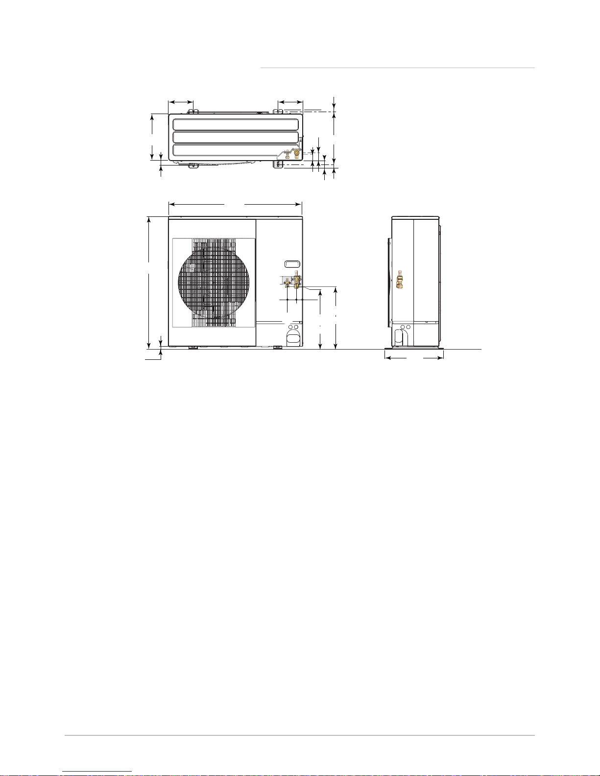
3.3.3 AWHP 8 MR-2
Fig.6
943
950
45
56
53 28
19
23
417
175
330
370
30
443
447
175
65 42
2
(A)
(B)
MW-M001442-2
1
1
3/8" refrigerant fluid connection
2
5/8" refrigerant gas connection
3 Technical specifications
20 AWHP-2 iMPI 7685645 - v04 - 07032018
Page 21
3.3.4 AWHP 11 MR-2 – AWHP 16 MR-2 – AWHP 11 TR-2 –
AWHP 16 TR-2
Fig.7
1350
950
45
56
53 28
19
23
417
175 600
330
370
30
443
447
175
65 42
2
(A)
(B)
1
MW-M001443-2
1
3/8" refrigerant fluid connection
2
5/8" refrigerant gas connection
3 Technical specifications
7685645 - v04 - 07032018 AWHP-2 iMPI 21
Page 22
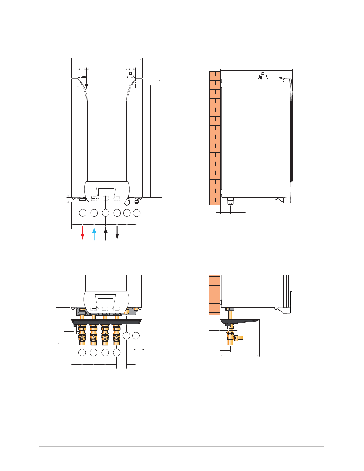
3.3.5 iMPI with hydraulic back-up
Fig.8 iMPI/H
MW-3000532-01
679
621
63
65
65
65
55
55
16
400
218
45
40
1
2
3 4 5
6
402
56,5
1 Heating circuit flow G 1"
2 Heating circuit return G 1"
3 Back-up boiler flow G 1"
4 Back-up boiler return G 1"
5 5/8" refrigerant gas connection
6 3/8" refrigerant fluid connection
Fig.9 iMPI/HI
MW-3000533-01
55
32
22
213
63 65 63 65
4321
5 6
57
211
48
1 Heating circuit flow G 1"
2 Heating circuit return G 1"
3 Back-up boiler flow G 1"
4 Back-up boiler return G 1"
5 5/8" refrigerant gas connection
6 3/8" refrigerant fluid connection
3 Technical specifications
22 AWHP-2 iMPI 7685645 - v04 - 07032018
Page 23
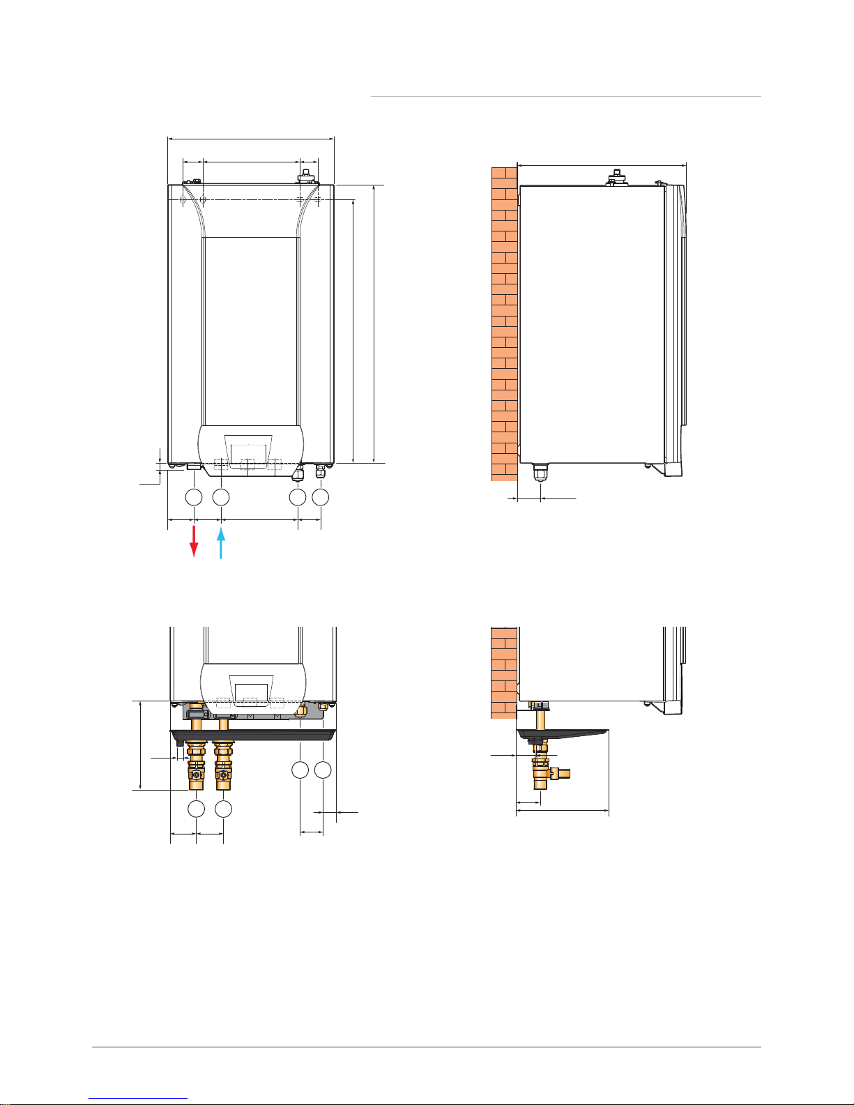
3.3.6 iMPI with electrical back-up
Fig.10 iMPI/EM, iMPI/ET
MW-3000530-01
400
218
45
40
679
621
63
65
185
55
16
21 3 4
56,5
402
1 Heating circuit flow G 1"
2 Heating circuit return G 1"
3 5/8" refrigerant gas connection
4 3/8" refrigerant fluid connection
Fig.11 iMPI/EMI, iMPI/ETI
MW-3000531-01
57
211
48
63
65
55
32
22
213
3
1 2
4
1 Heating circuit flow G 1"
2 Heating circuit return G 1"
3 5/8" refrigerant gas connection
4 3/8" refrigerant fluid connection
3 Technical specifications
7685645 - v04 - 07032018 AWHP-2 iMPI 23
Page 24
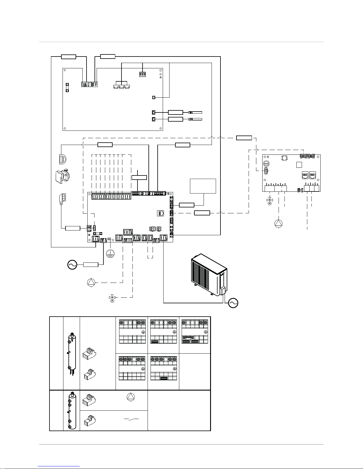
3.4 Electrical diagram
Fig.12
HPC-01
Sensor Liquid
Sensor Target
7679484
7622566
7685744
7679483
7619601
7679482
7679481
Low noise
Pump
3 Way Valve
DHW
Water
Sensors
7679489
2kW 230V~
6kW 400V 3N~
X7
X6
X5
X1
X2
X3
X4
X12
X11
FUSE
EHC-04
X8
X7
X6
X22
X27
X15
X26
X23
X30
X1
X4
X5
X19
X24
X25
X10
X9
X18
FUSE
X17
X16
X13
X21
X2
SCB-04B
X6
X8
X9
X1
X2
X3
SW2
FUSE
L1 L2 L3 D3 N
Hydraulic
Backup
Electric
Backup
7621758
ON/OFF
X4
EHC-04
X5
EHC-04
7622059
Pump
3 Way
Valve
Room Unit
T°C
Flow
Safety
Thermostat
Outdoor Unit
7681340
Pump
Harness
N° 7679488
Domestic Hot Water t° High
Domestic Hot Water t° Low
230V~
Outside temperature sensor
Room Unit
BL1 Multifunction
BL2 Multifunction
So+/So- Energy counter
Condensate sensor ON/OFF
9kW 400V 3N~
4kW 230V~
6kW 230V~
X4
EHC-04
X5
EHC-04
Pump
L1 L2 L3 D3 N
L1 L2 L3 D3 N
L1 L2 L3 D3 N
L1 L2 L3 D3 N
S2 / S3
7691321
MW-5000747-1
HMI
X28
X12
3 Technical specifications
24 AWHP-2 iMPI 7685645 - v04 - 07032018
Page 25

Tab.14 Wiring diagram legend
230 V ~ Power supply
3 WAY VALVE Three-way valve
3-WAY DHW VALVE 3-way domestic hot water valve
BL1 MULTIFUNCTION BL1 multifunction
BL2 MULTIFUNCTION BL2 multifunction
CONDENSATE SENSOR ON/OFF Underfloor heating
DOMESTIC HOT WATER T° HIGH Temperature at the top of the tank
DOMESTIC HOT WATER T° LOW Temperature at the bottom of the tank
EHC-04 Hybrid heat pump control system central unit PCB
ELECTRICAL BACKUP Electrical back-up
FUSE Fuse
HMI Control panel
HPC-01 HPC PCB (interface for the outdoor unit)
HYDRAULIC BACKUP Hydraulic back-up
LOW NOISE Silent option
OUTDOOR UNIT Outdoor unit
OUTDOOR TEMPERATURE SENSOR Outdoor temperature sensor
PUMP Circulating pump
ROOM UNIT Room thermostat
SAFETY THERMOSTAT Safety thermostat
SCB-04 PCB for controlling a second circuit (optional)
SENSOR LIQUID Exchanger refrigerant temperature sensor
SENSOR TARGET Water temperature sensor on the exchanger outlet
SO+/SO- ENERGY COUNTER SO+/SO- energy meter
T°C FLOW Second circuit heating flow temperature
WATER SENSORS Water sensors
3 Technical specifications
7685645 - v04 - 07032018 AWHP-2 iMPI 25
Page 26

4 Description of the product
4.1 Operating principle
The outdoor unit produces heat or cold and transfers it to the indoor mod
ule via the refrigerant in the plate exchanger. The indoor module is equip
ped with a specific control system which is used to adjust the temperature
of the heating water to the needs of the home.
4.2 Main components
1 Safety valve
2 Exchanger
3 Air vent
4 PCB box
5 Low-loss header
6 Pressure gauge
7 Display
8 Control panel
9 Circulating pump
10 Flow meter
11 8-litre expansion vessel
1 Safety valve
2 Exchanger
3 Air vent
4 Low-loss header with electrical back-up
5 PCB box
6 Pressure gauge
7 Display
8 Control panel
9 Circulating pump
10 Flow meter
11 8-litre expansion vessel
1 HPC–01 PCB: PCB for interface with the outdoor unit
2 EHC–04 central unit PCB: Control system for the heat pump and
the first heating circuit
Fig.13 iMPI/H
MW-3000535-01
9
2
3
5
4
7
6
8
11
1
10
Fig.14 iMPI/ET, iMPI/EM
MW-3000534-01
9
2
3
4
5
7
6
8
11
1
10
Fig.15 Position of the PCBs
MW-3000587-01
1
2
4 Description of the product
26 AWHP-2 iMPI 7685645 - v04 - 07032018
Page 27

4.3 Standard delivery
Delivery includes several packages:
One indoor module package
One outdoor unit package
Contents of the indoor module package:
An indoor module
An outside sensor
An installation and service manual
A user guide
4 Description of the product
7685645 - v04 - 07032018 AWHP-2 iMPI 27
Page 28
5 Before installation
5.1 Regulations governing installation
Warning
The heat pump must be installed by a qualified installer in accord
ance with local and national regulations.
Warning
The components used for the connection to the cold water supply
must comply with the prevailing standards and regulations in the
country concerned.
5.2
Installation requirements
5.2.1
Treatment of the heating water
In many cases, the heat pump and the heating system can be filled with
mains water, without treating the water.
Caution
Do not add any chemical products to the heating water without
first consulting a water treatment specialist. For example: anti
freeze, water softeners, products to increase or reduce the pH val
ue, chemical additives and/or inhibitors. These may cause faults in
the heat pump and damage the heat exchanger.
Important
Flush the installation with at least 3 times the volume of water
contained in the heating system.
Flush the DHW circuit with at least 20 times its volume of water.
The water in the installation must comply with following characteristics:
Tab.15 Heating water specifications
Specifications Unit
Total system output
≤ 70 kW
Hydrogen potential (pH) 7.5 - 9
Conductivity at 25°C μS/cm 10 to 500
Chlorides mg/litre ≤ 50
Other components mg/litre < 1
Total water hardness
°f 7 - 15
°dH 4 - 8.5
mmol/l 0.7 - 1.5
Important
If water treatment proves necessary, Baxi recommends the follow
ing manufacturers:
Cillit
Climalife
Fernox
Permo
Sentinel
5 Before installation
28 AWHP-2 iMPI 7685645 - v04 - 07032018
Page 29

5.2.2 Special precautions for the connection of the heating cir
cuit
When making the connection, it is imperative that the standards and corre
sponding local directives be respected.
Caution
The hydraulic installation must be capable of handling a minimum
flow rate at all times:
If radiators are connected directly to the heating circuit: install a
differential valve between the indoor module and the heating cir
cuit.
Leave one heating circuit without a thermostatic valve and/or
without a solenoid valve.
Fit drainage valves between the indoor module and the heating
circuit.
Install a filter on the heating return circuit.
5.3
Choice of the location
Decide on the ideal location, bearing in mind the space required by the
heat pump and any legal directives.
Install the heat pump's indoor module on a solid, stable structure capa
ble of bearing the weight of the heat pump when full of water and fitted
with its various accessories.
Install the indoor module as close as possible to the draw-off points in
order to minimise energy losses through the pipes.
Install the heat pump's outdoor module on a solid, stable structure.
Caution
The indoor module must be installed on frost-free premises.
5.3.1 Data plate
The data plates identify the product and provide the following important in
formation.
The data plates must be accessible at all times.
Important
Never remove or cover labels and data plates affixed to the appli
ances. Labels and data plates must be legible throughout the en
tire lifetime of the appliance.
Damaged or illegible instructions and warning stickers must be re
placed immediately.
5 Before installation
7685645 - v04 - 07032018 AWHP-2 iMPI 29
Page 30

Data plate on the indoor module
Data plate on the outdoor unit
5.3.2
Overall space needed by the indoor module
Allow sufficient space around the heat pump's indoor module to ensure
adequate access and facilitate maintenance.
Fig.16
MW-3000537-01
Fig.17
MW-M001832-1
Fig.18
MW-3000536-01
393
10
00
1200
400
500
500
670
100
5 Before installation
30 AWHP-2 iMPI 7685645 - v04 - 07032018
Page 31

5.3.3 Distance between modules
1 Outdoor unit
2 Indoor module
Allow a refrigeration connection of at least 2 m by making one or two
horizontal loops in order to lessen these disruptions. If the refrigeration
connection between the outdoor unit and the indoor module is less than
2 m, the following disruptions may occur:
Functional disruptions caused by a fluid overload
Noise pollution caused by the circulation of the refrigerant
Respect the minimum curve radii of 100 to 150 mm.
To ensure that the heat pump functions correctly, respect the minimum
and maximum connection lengths between the indoor module and the
outdoor unit.
Tab.16
Outdoor unit AWHP 4.5 MR AWHP 6 MR-3
AWHP 8 MR-2
AWHP 11 MR-2 AWHP 11 TR-2 AWHP 16 MR-2 AWHP 16 TR-2
A:
Maximum/mini
mum length
2 to 30 m 2 to 40 m 2 to 75 m 2 to 75 m 2 to 75 m 2 to 75 m
B:
Maximum height
difference
30 m 30 m 30 m 30 m 30 m 30 m
C:
Maximum num
ber of elbows
10 15 15 15 15 15
5.3.4 Installing the outdoor unit on the ground
When mounting on the ground, a concrete base must be installed, with no
rigid connection to the building served to avoid the transmission of vibra
tions.
The data plate must be accessible at all times.
1. Dig a run-off channel with a pebble bed.
2. Install a concrete base frame with a minimum height of 200 mm ca
pable of bearing the weight of the outdoor unit.
3. Install the outdoor unit on the concrete base frame.
Installation in cold and snowy regions
Wind and snow may significantly impair the performance of the heat
pump. Ensure that the following information is respected to install the out
door unit correctly.
Always install the outdoor unit sufficiently high off the ground to allow
correct condensates discharge.
The width of the base must not exceed the width of the outdoor unit.
Icing may lead to it breaking (refrigerant fluid leak).
The height of the base frame must be higher than the height of the
heaviest snowfalls. This measure helps to protect the exchanger from
snow and prevent the formation of ice during the defrosting operation.
For regions where heavy snowfalls occur, raise the above-ground pro
tection by at least 200 mm compared with the average depth of the cov
ering of snow.
Fig.19 Diagram of distances between mod
ules
MW-M00 1439-2
A
B
2
1
C
Fig.20
MW-M001452-3
200
2
1
3
5 Before installation
7685645 - v04 - 07032018 AWHP-2 iMPI 31
Page 32

Caution
If the outside temperatures become negative, take the necessa
ry precautions to prevent the risk of freezing in the evacuation
pipes.
Prevent any risk of the condensates freezing in a passing-by
zone.
Fig.21 Installation of a single outdoor unit or several outdoor units
MW-6000252-2
1 2 3/
4
1. Always install the outdoor unit as far as possible from the thorough
fare as the condensates discharge may freeze, causing a potential
hazard (sheet of black ice).
2. Place the outdoor units beside each other and not on top of each oth
er to prevent the condensates from the lower unit to freeze.
Installing a noise abatement screen
In some cases, additional precautions are necessary owing to the fact, for
example, of too short a distance between you and your neighbours.
Fig.22 Noise abatement screen
MW-C000373-1
Brrrrr....
Brrrrr....
Brrrrr....
Brrrrr....
Locate the noise abatement screen as close as possible to the noise
source whilst allowing for the free circulation of air in the exchanger on the
outdoor unit and maintenance work.
5 Before installation
32 AWHP-2 iMPI 7685645 - v04 - 07032018
Page 33

Fig.23 Distances of the appliance from the wall
MW-M001450-1
G
F
F
G
A
C
B
B
C
E
A
1000
D
M
ax. 500
M
ax. 500
Tab.17 Minimum dimensions in mm
AWHP 4.5 MR
AWHP 6 MR-3
AWHP 8 MR-2
AWHP 11 MR-2
AWHP 16 MR-2
AWHP 11 TR-2
AWHP 16 TR-2
A 100 150
B 500 1000
C 200 300
D 1000 1500
E 300 500
F 150 250
G 100 200
Position of the outdoor unit
Carefully choose the position of the outdoor unit in relation to neighbours
as it is a source of noise.
Warning
Nothing must obstruct the free circulation of air around the out
door unit (intake and outlet).
Do not place the outdoor unit close to where people sleep.
Do not place the unit opposite a wall with windows.
Avoid placing it close to a terrace, etc.
Choose a location away from prevailing winds.
Ensure sufficient above ground elevation (100 to 500 mm) to keep it above
water.
Always use a base with a metal frame sufficiently high off the ground to
allow correct condensates discharge. The width of the base must not ex
ceed the width of the outdoor unit.
Always install the outdoor unit sufficiently high off the ground to allow cor
rect condensates discharge.
Fig.24 Position of the outdoor unit
MW-M001448-2
5 Before installation
7685645 - v04 - 07032018 AWHP-2 iMPI 33
Page 34

Important
The condensates discharge must be regularly cleaned in order to
prevent any blockages.
5.4 Fitting the outdoor sensor
1. Choose the optimum location for the outdoor sensor.
2. Put the 2 plugs in place, delivered with the sensor (diameter 4 mm).
3. Secure the sensor using the screws provided (diameter 4 mm).
4. Connect the cable to the outdoor temperature sensor.
5.4.1 Recommended positions
Place the outside sensor in a position that covers the following character
istics:
On a façade of the area to be heated, on the north if possible.
Half way up the wall of the area to be heated.
Under the influence of changes in the weather.
Protected from direct sunlight.
Easy to access.
Fig.26
MW-8800N001-3
2
1
2
1
1
2
H
1/2 H (min. 2,5 m)
1/2 H (min. 2,5 m)
1/2 Z
H
Z
1
Recommended position
2
Possible position
H
Inhabited height controlled by the sensor
Z
Inhabited area controlled by the sensor
5.4.2 Positions to be avoided
Avoid placing the outside sensor in a position with the following character
istics:
Masked by part of the building (balcony, roof, etc.).
Close to a disruptive heat source (sun, chimney, ventilation grid, etc.).
Fig.25 Mounting the outdoor sensor
MW-8800N003-6
2
3
4
5 Before installation
34 AWHP-2 iMPI 7685645 - v04 - 07032018
Page 35

Fig.27
MW-3000014-2
5 Before installation
7685645 - v04 - 07032018 AWHP-2 iMPI 35
Page 36

6 Connecting diagrams
6.1 Connection for the iMPI heat pump with electrical back-up with a domestic hot water tank and an
underfloor heating circuit
Fig.28 iMPI with a domestic hot water tank, an underfloor heating circuit, a TXM connected thermostat and an electrical
back-up
MW-5000759-2
230V ou 400V
50Hz
BUS
230V 50Hz
M
AB
A
B
3
1
6
4
5
6
7
8
8
9
2
1 Outdoor unit
2 Connected thermostat
TXM
3 Indoor module with electrical back-up
4 Direct underfloor heating connection kit
5 1/4” to 3/8” connection for AWHP 4.5 MR and AWHP
6 MR-3
6 Kit comprising heating/DHW reversing valve + do
mestic hot water sensor
7 Filter and isolation valve kit
8 Hydraulic connection kit for one domestic hot water
tank
9 Refrigeration connection kit 1/2" - 1/4"
6 Connecting diagrams
36 AWHP-2 iMPI 7685645 - v04 - 07032018
Page 37

6.1.1 Connect and configure the iMPI heat pump with electrical
back-up with a domestic hot water tank and a direct cir
cuit
Fig.29
MW-5000766-2
230V ou 400V
50Hz
230V 50Hz
M
AB
A
4
2
5
3
X23
X12 X28
1
3
8
5
X25
4
1
8
2
B
EHC-04
1 Outdoor temperature sensor
2 Wiring kit for direct underfloor heating
3 TXM connected thermostat
4 Heating/domestic hot water reversal valve
5 Domestic hot water sensor
8 Outdoor unit bus connection
1. Connect the accessories and options to the EHC–04 PCB, respect
ing the 230-400 V and 0-40 V cable feed-throughs.
2. On initial start-up, or after a reset of the factory parameters, set the
CN1 and CN2 parameters according to the output of the outdoor
unit.
3. Select the number corresponding to the installation type by pressing
the or key.
Installation type No.
1 direct underfloor heating + 1 domestic hot water tank 06
Selecting the installation type enables automatic configuration of
the parameters required for the control panel to operate correctly
(gradient, maximum circuit temperature, etc.).
4. Confirm the selection by pressing the key.
The main parameters are set.
6 Connecting diagrams
7685645 - v04 - 07032018 AWHP-2 iMPI 37
Page 38

6.2 Connection for the iMPI heat pump with electrical back-up with 2 circuits and a buffer tank
Fig.30 iMPI with a direct circuit, a circuit with mixing valve, two TXM connected thermostats and an electrical back-up
MW-5000757-2
M
Ö& Ö& Ö& Ö&
6
1
2
3
9
8
10
7
11
4
5
230V
50Hz
BUS
1 Outdoor unit
2 Indoor module with electrical back-up
3 Thermostat connected to circuit A
4 Refrigeration connection 5/8" – 3/8", 10 m
5 Second circuit control system PCB kit
6 Filter and isolation valve kit
7 Collector for 2/3 circuits
8 Direct circuit kit with circulating pump
9 Thermostat connected to circuit B
10 Three-way valve circuit kit with circulating pump
11 Buffer tank
6 Connecting diagrams
38 AWHP-2 iMPI 7685645 - v04 - 07032018
Page 39

6.2.1 Connect and configure the iMPI heat pump with electrical
back-up with 2 circuits and a buffer tank
Fig.31
MW-5000768-3
M
Ö& Ö& Ö& Ö&
2
5
6
1
7
3
230V
50Hz
X7
X23
X6
X8
X15
X12 X28
1
2
6
9
9
5
10
10
7
8
3
4
4
1
8
11
11
SCB-04B
EHC-04
1 Outdoor temperature sensor
2 Safety thermostat for underfloor heating flow
3 Thermostat connected to circuit B
4 Flow sensor on circuit B
5 Pump supply on circuit B
6 Supply of the three-way valve on circuit B kit
7 Thermostat connected to circuit A
8 Outdoor unit bus connection
9 230 V power supply connection between the EHC–
04 and SCB-04 PCBs
10 BUS connection linking the EHC–04 and SCB-04
PCBs
11 Pump supply on circuit A
1. Connect the accessories and options to the EHC–04 PCB, respect
ing the 230-400 V and 0-40 V cable feed-throughs.
2. Connect the accessories and options to the SCB-04 PCB, respect
ing the 230-400 V and 0-40 V cable feed-throughs.
3. On initial start-up, or after a reset of the factory parameters, set the
CN1 and CN2 parameters according to the output of the outdoor
unit.
4. Select the number corresponding to the installation type by pressing
the or key.
Installation type No.
1 direct heating circuit and 1 underfloor heating circuit
with mixing valve
03
Selecting the installation type enables automatic configuration of
the parameters required for the control panel to operate correctly
(gradient, maximum circuit temperature, etc.).
5. In the Installer \ EHC–04 \ ADV menu, configure the HP086 pa
rameter to 1.
6. Confirm the selection by pressing the key.
The main parameters are set.
6 Connecting diagrams
7685645 - v04 - 07032018 AWHP-2 iMPI 39
Page 40

6.3 Connection for the iMPI heat pump with electrical back-up with 2 circuits with a low-loss header
Fig.32 iMPI with a direct circuit, a circuit with mixing valve, two TXM connected thermostats and an electrical back-up
BUS
MW-5000760-2
4
230V
50Hz
5
6
8
7
2
1
9
3
1 Outdoor unit
2 Indoor module with electrical back-up
3 Refrigeration connection 5/8" – 3/8", 10 m
4 Second circuit control system PCB kit
5 Thermostat connected to circuit B
6 Thermostat connected to circuit A
7 Hydraulic kit with one direct circuit and one 3-way
valve circuit
8 Low-loss header
9 Filter and isolation valve kit
6 Connecting diagrams
40 AWHP-2 iMPI 7685645 - v04 - 07032018
Page 41

6.3.1 Connect and configure the iMPI heat pump with electrical
back-up with a direct circuit, a circuit with mixing valve, a low-loss
header and two TXM connected thermostats
Fig.33
8
1
1
MW-5000769-2
230V
50Hz
7
4
5
6
X7
X23
X6
X8
X15
X12 X28
1
2
6
9
9
5
10
10
7
8
3
4
2
3
1
8
11
11
X26
SCB-04B
EHC-04
1 Outdoor temperature sensor
2 Safety thermostat for underfloor heating flow
3 Thermostat connected to circuit B
4 Flow sensor on circuit B
5 Pump supply on circuit B
6 Supply of the three-way valve on circuit B
7 Thermostat connected to circuit A
8 Outdoor unit bus connection
9 230 V power supply connection between the EHC–
04 and SCB-04 PCBs
10 BUS connection linking the EHC–04 and SCB-04
PCBs
11 Pump supply on circuit A
1. Connect the accessories and options to the EHC–04 PCB, respect
ing the 230-400 V and 0-40 V cable feed-throughs.
2. Connect the accessories and options to the SCB-04 PCB, respect
ing the 230-400 V and 0-40 V cable feed-throughs.
3. On initial start-up, or after a reset of the factory parameters, set the
CN1 and CN2 parameters according to the output of the outdoor
unit.
4. Select the number corresponding to the installation type by pressing
the or key.
Installation type No.
1 direct heating circuit and 1 underfloor heating circuit
with mixing valve
03
Selecting the installation type enables automatic configuration of
the parameters required for the control panel to operate correctly
(gradient, maximum circuit temperature, etc.).
5. In the Installer \ EHC–04 \ ADV menu, configure the HP086 pa
rameter to 1.
6. Confirm the selection by pressing the key.
The main parameters are set.
6 Connecting diagrams
7685645 - v04 - 07032018 AWHP-2 iMPI 41
Page 42

6.4 Connection for the iMPI heat pump with hydraulic back-up with a direct circuit
Fig.34 iMPI with a direct circuit, a TXM connected thermostat and a hydraulic back-up
BUS
2
7
3
5
230V
50Hz
MW-5000758-2
4
1
6
230V
50Hz
1 Outdoor unit
2
Connected thermostat
3 Indoor module
4
Direct underfloor heating connection kit
5
Floor-standing gas/oil-fired boiler
6
Filter and isolation valve kit
6.4.1 Connect and configure the iMPI heat pump with hydraulic
back-up with a direct circuit
Fig.35
X23 X4
X12
X28
13
8
X5
4 2
3
230V
50Hz
MW-5000767-2
5
230V
50Hz
1
5
2
4
8
EHC-04
1 Outdoor temperature sensor
2 Hydraulic back-up pump
3 Thermostat
4 ON/OFF contact for the hydraulic back-up
5 Safety thermostat for underfloor heating flow
8 Outdoor unit bus connection
6 Connecting diagrams
42 AWHP-2 iMPI 7685645 - v04 - 07032018
Page 43

1. Connect the accessories and options to the EHC–04 PCB, respect
ing the 230-400 V and 0-40 V cable feed-throughs.
2. On initial start-up, or after a reset of the factory parameters, set the
CN1 and CN2 parameters according to the output of the outdoor
unit.
3. Select the number corresponding to the installation type by pressing
the or key.
Installation type No.
1 direct underfloor heating circuit 05
Selecting the installation type enables automatic configuration of
the parameters required for the control panel to operate correctly
(gradient, maximum circuit temperature, etc.).
4. Confirm the selection by pressing the key.
The main parameters are set.
5. If necessary, configure the hybrid operating mode for the hydraulic
back-up
6. Setting up the back-up boiler
6 Connecting diagrams
7685645 - v04 - 07032018 AWHP-2 iMPI 43
Page 44

7 Installation
7.1 General
Caution
Installation of the heat pump must be done by a qualified profes
sional in accordance with prevailing local and national regulations.
7.2
Preparation
7.2.1 Mounting the indoor module
Fitting the mounting rail
1. Drill 2 holes with a diameter of 10 mm.
Important
Extra holes are provided in case one or other of the standard lo
cating holes prevents the correct location of the plug.
2. Put the plugs in place.
3. Fix the mounting rail to the wall using the hexagonal head screws
provided for this purpose. Set the level using a spirit level.
Mounting the module on the wall
1. Position the indoor module above the mounting rail so that it rests
snugly against it.
2. Gently lower the indoor module.
Fig.36 Drilling and mounting the rail
2
3
3
1
MW-2000075-1
340
ø10
250
Fig.37 Assembling the module
MW-3000538-2
7 Installation
44 AWHP-2 iMPI 7685645 - v04 - 07032018
Page 45

7.3 Hydraulic connections
7.3.1 Connecting the heating circuit
Heating installations must be able to guarantee a minimum flow rate at all
times. This is defined by the parameter HP010. The nominal flow rate
sought by the heat pump for optimum running is defined by the parameter
HP069. If the flow rate is too low, the heat pump may shut itself down for
its own protection; the heating, cooling and domestic hot water functions
are then no longer guaranteed.
Important
To ensure maintenance and accessibility to the various compo
nents in the module, the hydraulic pipes have been purposely de
signed with a degree of play. This play is necessary and control
led. This pipe design guarantees the tightness of the product.
1. Make the hydraulic connections between the indoor module, the
heating circuit and the boiler if there is hydraulic back-up
Warning
To ensure optimum operation of the back-up boiler, the flow rate
of the boiler must always be higher than that of the installation.
2. Install a 500 µm filter on the heating return of the indoor module
(mandatory): Optional package .
Caution
Respect the mounting direction of the filter.
Fit drainage valves between the indoor module and the heating
circuit.
3. Install an automatic air vent at the highest point on the heating cir
cuit.
4. Calculate the volume of water in the heating circuit and check the
volume of the appropriate expansion vessel using DTU65–11. Use
the maximum temperature of the circuit in heating mode or, failing
that, a minimum of 55 °C. If the volume of the integrated 8-litre ex
pansion vessel is not sufficient, add an external vessel to the heat
ing circuit.
5. Connect the heating return for the indoor module.
6. Connect the heating flow for the indoor module.
Caution
When connecting the heating circuit, hold the connection at the in
door module end with a spanner to avoid piercing the pipe inside
the appliance.
Caution
In case of a direct circuit with radiators fitted with thermostatic
valves, install a differential valve to ensure flow. In the case of
standard valves, leave one radiator permanently open to allow wa
ter to circulate and to ensure a minimum flow.
7 Installation
7685645 - v04 - 07032018 AWHP-2 iMPI 45
Page 46

7.3.2 Connecting the safety valve drain pipe
1. Remove the front panel by pulling firmly upwards.
2. Pass the outlet pipe from the safety valve through the opening provi
ded for this purpose.
3. Connect the outlet pipe to the waste water discharge.
Caution
The discharge pipe in the safety valve or unit must not be blocked.
7.4 Refrigeration connections
7.4.1 Installing the refrigeration link
1. Install the refrigerant connection pipes between the indoor module
and the outdoor unit.
2. Ensure the minimum bending radii of 100 to 150 mm and the pipe
characteristics are observed.
3. Cut the pipes with a pipe cutter and deburr; angle the opening in the
pipe downwards to ensure no particles can get inside.
4. After completing the installation and all checks necessary before
commissioning, add refrigerant fluid if the refrigeration connection
pipes are more than 10 metres long.
Quantity of refrigerant fluid to be added
If the refrigeration connection pipes are more than 10 metres long, add
more refrigerant fluid.
Caution
Prevent oil traps.
If the pipes are not connected immediately, plug them to prevent
moisture from entering.
Tab.18 For AWHP 4.5 MR
Length of refrig
eration pipe
7 m 10 m 15 m 20 m 30 m Yg/m
Charging
(1)
0 + 0.045 kg + 0.120 kg + 0.195 kg + 0.345 kg
15
(2)
Fig.38 Removing the front panel
MW-3000539-01
1
Fig.39 Orifice
MW-3000540-01
2
7 Installation
46 AWHP-2 iMPI 7685645 - v04 - 07032018
Page 47

Length of refrig
eration pipe
7 m 10 m 15 m 20 m 30 m Yg/m
(1) The outdoor module is pre-charged with 1,300 kg of refrigerant fluid.
(2) Calculation: Xg = Yg/m x (pipe length (m) – 7)
Tab.19
Length of refrigeration pipe AWHP 6 MR-3 AWHP 8 MR-2 AWHP 11 MR-2
AWHP 16 MR-2
AWHP 11 TR-2
AWHP 16 TR-2
11 to 20 m + 0.2 kg + 0.15 kg + 0.2 kg
21 to 30 m + 0.4 kg + 0.3 kg + 0.4 kg
31 to 40 m + 0.6 kg + 0.9 kg + 1 kg
41 to 50 m not permitted not permitted + 1.6 kg
51 to 60 m not permitted not permitted + 2.2 kg
61 to 75 m not permitted not permitted + 2.8 kg
7.4.2 Connecting the refrigeration link
Important
Use a flat spanner to hold the hoses during the various opera
tions.
1. Partially unscrew the 5/8" nut.
Fig.40 Holding with a flat spanner
MW-3000541-01
Fig.41 Partial loosening of the 5/8" nut
MW-3000542-01
1
7 Installation
7685645 - v04 - 07032018 AWHP-2 iMPI 47
Page 48

2. Push a screwdriver gently into the 5/8" nut. A release noise should
be heard, which is proof that the exchanger is watertight.
3. Unscrew the 3/8" and 5/8" nuts.
4. Depending on each specific case:
Option Model Action
A Only for models
AWHP 4.5 MR
AWHP 6 MR-3
Throw the nuts in the
bin
B For other models Remove and discard
the 3/8" and 5/8" caps
5. Only for the , - AWHP 4.5 MR models: Mount the 1/4" adapter fit
tings to the 3/8" and the 1/2" to the 5/8" (separate package ).
6. Slip the nuts onto the pipes.
7. Bead the pipes.
Fig.42 Release noise
MW-3000543-01
OK
Pfffff...
2
Fig.43 Unscrewing the 3/8" and 5/8" nuts.
MW-3000598-01
3
Fig.44 Discarding the nuts or caps
MW-3000599-01
4
4
A
B
Fig.45 Mounting the fittings
MW-3000545-01
5
Fig.46 Fitting the nuts
MW-M002207-1
6
7
7 Installation
48 AWHP-2 iMPI 7685645 - v04 - 07032018
Page 49

8. Connect the pipes and tighten the nuts with a dynamometric span
ner.
Notice
Apply refrigerant oil to the beaded parts to facilitate tightening and
improve the seal.
Option Model
A Only for models
AWHP 4.5 MR
B For other models
Tab.20 Torque load
External diameter of
the pipe (mm/inch)
External diameter of
the cone fitting (mm)
Torque load (N.m)
6.35 - 1/4 17 14 - 18
9.52 - 3/8 22 34 - 42
12.7 - 1/2 26 49 - 61
15.88 - 5/8 29 69 - 82
9. Remove the protective side panels from the outdoor unit.
10. Unscrew the nuts on the stop valves.
11. Slip the nuts onto the pipes.
12. Bead the pipes.
Fig.47 Connecting the pipes
MW-L000281-1
8
A
8
B
Fig.48 Removing the side panels
9
9
MW-M002209-1
Fig.49 Unscrewing the nuts on the stop
valves
MW-M002210-1
10
11
12
7 Installation
7685645 - v04 - 07032018 AWHP-2 iMPI 49
Page 50

13. Connect the pipes and tighten the nuts with a dynamometric span
ner.
Notice
Apply refrigerant oil to the beaded parts to facilitate tightening and
improve the seal.
A Do not use a spanner on this part of the valve, danger of the refrig
erant leaking
B Recommended position of the spanners for tightening the nut
Tab.21 Torque load
External diameter of
the pipe (mm/inch)
External diameter of
the cone fitting (mm)
Torque load (N.m)
6.35 - 1/4 17 14 - 18
9.52 - 3/8 22 34 - 42
12.7 - 1/2 26 49 - 61
15.88 - 5/8 29 69 - 82
7.4.3 Test the tightness
1. Open the plugs in isolation valves A and B / C.
2. Check that isolation valves A and B / C are closed.
3. Remove the plug from the service connection on isolation valve A.
4. Connect the pressure gauge and the nitrogen bottle to the stop
valve A then progressively build up the pressure in the refrigerant
connection pipes and the indoor module to 35 bar, in 5 bar incre
ments.
5. Check the tightness of the fittings using a leak detector spray. If
leaks appear, repeat the steps in order and check the tightness once
again.
6. Release the pressure and release the nitrogen.
Fig.50 Connecting the pipes
MW-M002211-1
13
A
B
B
Fig.51 Isolation valves
MW-M002297-2
A
B
C
35 bar
1
1
1
2
2
2
5
3
4
7 Installation
50 AWHP-2 iMPI 7685645 - v04 - 07032018
Page 51

7.4.4 Evacuation
1. Check that isolation valves A and B / C are closed.
2. Connect the vacuum gauge and the vacuum pump to the service
connection on isolation valve A.
3. Produce a vacuum in the indoor module and the refrigeration con
nection pipes.
4. Check the pressure using the recommendations table below:
Tab.22
Outside temperature °C ≥ 20 10 0 - 10
Pressure to be reached
Pa
(bar)
1000
(0.01)
600
(0.00
6)
250
(0.00
25)
200
(0.00
2)
Evacuation time after reach
ing the pressure
h 1 1 2 3
5. Close the valve between the vacuum gauge / vacuum pump and iso
lation valve A.
6. After shutting off the vacuum pump, immediately open the valves.
7.4.5 Opening the valves
1. Remove the cap from the refrigerant fluid isolation valve, fluid end.
2. Open valve A with a hexagonal spanner by turning anti-clockwise
until it stops.
3. Put the cap back in place.
4. Remove the cap from refrigerant gas isolation valve B or C.
5. Open the valve.
Valve B Open the valve with pliers by turning it a quar
ter turn anti-clockwise.
Valve C Open the valve with a hexagonal spanner by
turning anti-clockwise until it stops.
6. Put the cap back in place.
7. Disconnect the vacuum gauge and the vacuum pump.
8. Put the cap back in place on valve A.
9. Tighten all the caps with a torque wrench with a torque load of 20 to
25 N·m.
10. Check the tightness of the connections using a leak detector.
11. If the refrigeration pipes are more than 10 metres long, add the re
quired quantity of refrigerant fluid.
For more information, see
Installing the refrigeration link, page 46
7.5
Electrical connections
7.5.1 Recommendations
Warning
Only qualified professionals may carry out electrical connec
tions, always with the power off.
Earth the appliance before making any electrical connections.
Make the electrical connections on the appliance in accordance with the
requirements of the prevailing standards,
Fig.52 Stop valves
MW-M002499-2
A
B
C
1
1
1
2
4
Fig.53 Isolation valve caps
MW-M002295-2
1
8
3
5
4
6
2
4
6
5
A
B
C
7 Installation
7685645 - v04 - 07032018 AWHP-2 iMPI 51
Page 52

Make the electrical connections on the appliance in accordance with the
information given in the electrical schematics delivered with the appli
ance,
Make the electrical connections on the appliance in accordance with the
recommendations of these instructions.
Important
Earthing must comply with the prevailing installation standards.
Caution
The installation must be fitted with a main switch.
Three phase models must always be fitted with neutral.
Caution
Power the appliance via a circuit that includes an omnipolar switch
with contact opening distance of 3 mm or more.
Single phase models: 230 V (+6%/-10%) 50 Hz
Three-phase models: 400 V (+6%/-10%) 50 Hz
When making electrical connections to the mains, respect the following
polarities.
Tab.23
Colour of the wire Polarity
Brown wire Live
Blue wire Neutral
Green/yellow wire Earth
Caution
Secure the cable with the cable clamp provided. Be careful that
you do not invert any of the wires.
7.5.2 Routing the cables
1 Cables for 230/400 V circuits and electrical back-up
2 0 - 40 V sensor cables
Fig.54
0-40V
MW-5000755-1
1
2
230-400V
7 Installation
52 AWHP-2 iMPI 7685645 - v04 - 07032018
Page 53

Caution
Separate the sensor cables from the 230/400 V circuit cables.
7.5.3
Description of the connection terminal blocks
EHC–04 PCB terminal block
X1
230 V - 50 Hz power supply
X4 Hydraulic version: Hydraulic back-up pump
Electrical version: Electrical back-up - stage 1
X5 Hydraulic version: Hydraulic back-up ON/OFF contact
Electrical version: Electrical back-up - stage 2
X7
CAN bus to the SCB-04 PCB
X8
Control panel display for the indoor module
X9
Sensors
X10
Main circulating pump command signal
X12
Options
R-Bus: Room temperature sensor/thermostat on/off or modulat
ing thermostat/OpenTherm
BL1 IN / BL2 IN: Multi-function inputs
So+/So- : Electric energy meter
Condensation: condensation sensor
X15
230-V power supply for the SCB-04 PCB
X17
Not used
X18
Input/output for the HPC–01 PCB
X19
Silent Mode option
X22
Bus connection to the PCB managing the HPC–01 outdoor unit
X23
Outdoor unit bus connection
X24
Electricity supply to the HPC–01 PCB (management of the outdoor
unit)
X25
Heating / Domestic hot water directional valve
X26
Pump - only if connecting a buffer tank
X27
Main circulating pump
X28
Outside sensor and domestic hot water tank temperature sensors
SCB-04 PCB terminal block
X1
Power supply for the pump/Three-way valve/Safety valve input
X2
PWM pump
X6
230 V power supply
X3
R-Bus: Room temperature sensor/thermostat on/off or modulat
ing/OpenTherm thermostat
Tout: Outdoor temperature sensor
Tflow: Flow sensor
X8 BUS
X9
BUS
7.5.4
Recommended cable cross section
The electrical characteristics of the mains power supply available must
correspond to the values given on the data plate.
The cable will be carefully chosen according to the following information:
Maximum intensity of the outdoor unit. See table below.
Distance of the appliance from the original power supply.
Upstream protection.
Neutral operating conditions.
Fig.55
Indoor module terminal block
MW-1001169-01
R-Bus
BL1 IN
BL2 IN
So+ So-
Condensation
X15
X26
X2 X25
X13 X6 X21
X28
X24
X12
X9
X4
X5
X19
X17
X16
X10
X23
X30
X18
X1
X20
EHC-04
X7 X8
X27
X22
}
Fig.56
MW-3000557-03
X8 X9
X3
X2
X1
FUSE
SW2
X6
7 Installation
7685645 - v04 - 07032018 AWHP-2 iMPI 53
Page 54

Tab.24 Outdoor unit
Unit AWHP
4.5 MR
AWHP 6
MR-3
AWHP 8
MR-2
AWHP 11
MR-2
AWHP 11
TR-2
AWHP 16
MR-2
AWHP 16
TR-2
Power supply type Single
phase
Single
phase
Single
phase
Single
phase
Three
phase
Single
phase
Three
phase
Cross section of the power sup
ply cable
mm² 3 x 2.5 3 x 2.5 3 x 4 3 x 6 5 x 2.5 3 x 10 5 x 2.5
Circuit breaker curve C A 20 16 25 32 16 40 16
Maximal amperage A 12 13 19 28 13 29 13
Tab.25 Indoor module
Cross section of the power supply cable mm² 3 x 1.5
Circuit breaker curve C A 10
BUS cable cross section
(1)
mm² 2 x 1.5
(1) Connection cable linking the outdoor unit to the indoor module
Tab.26 Connecting the electrical back-up
Unit Single phase Three phase
Cable cross section mm² 3 x 6 5 x 2.5
Circuit breaker curve C A 32 16
7.5.5 Accessing the PCBs and connection terminal block
1. Remove the front panel by pulling firmly upwards.
2. Remove the plate concealing the PCBs. Fig.57
MW-3000546-01
2
1
7 Installation
54 AWHP-2 iMPI 7685645 - v04 - 07032018
Page 55

3. Pivot the PCB support for routing the cables and connecting certain
options.
Connecting the cables to the PCBs
Use original connectors inserted into the various terminal blocks.
The connectors are keyed.
If there are no connectors on the terminal block to be used, use the con
nector provided with the kit.
Before feeding the cables into the cable feed-throughs, use the coloured
labels provided with some accessories to mark each end of the cable
with the same colour.
1. Insert and screw down the wires in the corresponding connector in
puts.
2. Insert the connector into the corresponding terminal block.
3. Feed the cable into the cable duct and adjust the length of the cable
accordingly. Lock it in position with a cable clamp or a traction ar
rester device.
Caution
Danger of electric shock: the length of the conductors between the
traction arrester device and the terminal blocks must be such that
the active conductors are put under tension before the earth con
ductor.
Fig.58
MW-3000597-01
3
Fig.59 Mounting a connector
MW-6000148-2
1
2
7 Installation
7685645 - v04 - 07032018 AWHP-2 iMPI 55
Page 56

7.5.6 Electrically connecting the outdoor unit
Fig.60
MW-2000376-3
1
2
1
2
L1 L2 L3 N
S1 S2 S3
1
2
A B C
A Single-phase power supply for AWHP 4.5 MR
B Single-phase power supply for AWHP 6 MR-3,
AWHP 8 MR-2, AWHP 11 MR-2 , AWHP 16 MR-2
C Three-phase power supply for AWHP 11 TR-2,
AWHP 16 TR-2
1 Power supply
2 Communication bus
7 Installation
56 AWHP-2 iMPI 7685645 - v04 - 07032018
Page 57

1. Remove the service panel.
D Service panel for AWHP 4.5 MR
E Service panel for AWHP 6 MR-3, AWHP 8 MR-2,
AWHP 11 MR-2 , AWHP 16 MR-2
F Service panel for AWHP 11 TR-2, AWHP 16 TR-2
2. This step is only valid for AWHP 4.5 MR: Remove the earth connec
tion present on the appliance and discard.
3. Check the cross-section of the cable used, as well as its protection
in the distribution board.
4. Step 4 is only valid for the AWHP 4.5 MR model. Secure the screw
and square washer provided on the stripped part of the earth wire
.
Danger
The stripped part of the earth wire must be fitted underneath the
washer against the base frame.
5. Connect the earth wire.
Danger
The earth wire must be 10 mm longer than the N and L wires.
6. Connect the cables to the appropriate terminals.
7. Feed the cable into the cable duct and adjust the length of the cable
accordingly. Lock it in position with a cable clamp or a traction ar
rester device.
Caution
Danger of electric shock: the length of the conductors between the
traction arrester device and the terminal blocks must be such that
the active conductors are put under tension before the earth con
ductor.
Fig.61
MW-1000787-3
1
2
MW-1000787-2
1
7
D
E
F
230V~
NEW
4
5
6
7
230V~
L
N
10mm
1
7
7 Installation
7685645 - v04 - 07032018 AWHP-2 iMPI 57
Page 58

7.5.7 Connecting the outdoor unit bus
1. Connect the outdoor unit bus to the X23 connector in the indoor
module's EHC–04 central unit PCB.
2. Position the SW8–3 switch (except with the AWHP 4.5 MR) for the
outdoor unit PCB to ON.
7.5.8 Connecting the outside sensor
1. Connect the outside sensor to the Tout input on the X28 connector
on the indoor module's EHC–04 central unit PCB.
Important
Use a cable with a minimum cross-section of 2x0.35 mm2.
7.5.9 Connecting the hydraulic back-up.
1. Connect the back-up boiler pump (live / neutral / earth) to the X4
connector on the EHC–04 central unit PCB in the indoor module.
2. Connect the dry ON/OFF contact in the back-up boiler to the X5 con
nector in the EHC–04 central unit PCB in the indoor module.
Fig.62
MW-3000588-01
N
L
S1
S2
S3
S
2
S3
X23
S
2
S3
S3
X23
2
S
1
312
SW8
2
Fig.63 Connecting the outside sensor
MW-3000513-01
X28
X28
1
1
7 Installation
58 AWHP-2 iMPI 7685645 - v04 - 07032018
Page 59

7.5.10 Connecting the power supply for the electrical back-up
1. Choose the total output of the electrical back-up according to the
size of the home and its energy performance. There are 2 output
stages, as shown in the following table:
Tab.27 Electrical back-up power supply
Back-up power supply Output of the electrical back-up
Stage 1 Stage 2 Maximum output (Stage 1 +
Stage 2)
Single phase 2 kW 0 kW 2 kW
2 kW 2 kW 4 kW
2 kW 4 kW 6 kW
Three phase 3 kW 3 kW 6 kW
3 kW 6 kW 9 kW
2. Feed the electrical back-up power supply cable into the cable duct
reserved for the 230/400 V circuit cables.
3. Single-phase power supply:
Insert the bridge according to the output of the electrical back-up,
taking care to push it to the bottom of the connector.
Connect the electrical back-up power supply (press the button to
be able to insert the wire into the connector correctly and secure
it).
Insert the electrical back-up power cord into the cable way located
in the bottom part of the junction box.
Important
The bridge can be found in a bag inside the indoor module.
A Bridge
B Button
L1 Live
N Neutral
Earth
Tab.28 Single-phase power supply
Maximum output Bridge to be installed
2 kW Do not install a bridge.
4 kW A
6 kW A
Fig.64 Single-phase power supply
2kW 230V~
L1 L2 L3 D3 N
4kW 230 V~
6kW 230V~
L1 L2 L3 D3 N
L1 L2 L3 D3 N
MW-5000774-1
B
A
7 Installation
7685645 - v04 - 07032018 AWHP-2 iMPI 59
Page 60

4. Three-phase power supply:
Insert the bridge according to the output of the electrical back-up,
taking care to push it to the bottom of the connector.
Connect the electrical back-up power supply (press the button to
be able to insert the wire into the connector correctly and secure
it).
Insert the electrical back-up power cord into the cable way located
in the bottom part of the junction box.
Important
The bridge can be found in a bag inside the indoor module.
A Bridge
B Button
L1 Live 1
L2 Live 2
L3 Live 3
N Neutral
Earth
Tab.29 Three-phase power supply
Maximum output Bridge to be installed
6 kW Do not install a bridge.
9 kW A
Fig.65 Three-phase power supply
6kW 400V 3N~
9kW 400V 3N~
L1 L2 L3 D3 N
L1 L2 L3 D3 N
MW-5000775-1
A
B
7 Installation
60 AWHP-2 iMPI 7685645 - v04 - 07032018
Page 61

Connecting a boiler fitted with a control panel with no input
TAM
Fig.66 Boiler fitted with a control panel with no input TAM
M
BUS
230V
MW-C003337-1
N
L
1
170
170
171
A
B
C
1 Domestic hot water load pump power supply CS Safety contact
1. Connect the electrical cables as per the connection diagram.
2. Set the following installer parameters on the boiler control panel:
Switch the boiler control system to 24h/24 comfort mode.
Heating set point temperature = on the indoor module.
7 Installation
7685645 - v04 - 07032018 AWHP-2 iMPI 61
Page 62

Connecting a boiler fitted with a control panel with an input
TAM
Fig.67 Boiler fitted with a control panel with an input TAM
BUS
MW-C003336-1
TAM
2 x 0,75 mm2
170
170
171
A
B
C
1 Domestic hot water load pump power supply TAM Room thermostat
7.5.11 Connecting a swimming pool
The swimming pool is not heated when the contact is open (factory set
ting). Only the frost protection continues to run.
The electrical connection of a swimming pool is made to the optional
SCB-04 PCB.
1. Connect the secondary pump from the swimming pool to the ter
minal block.
2. Connect the temperature sensor from the swimming pool to the
TFlowterminal block.
3. Connect the primary pump from the swimming pool to the termi
nal block.
4. Connect the swimming pool heating cut-off control to the R-Bus ter
minal block.
Fig.68 Connecting a swimming pool
MW-6000381-5
1
2
3
4
7 Installation
62 AWHP-2 iMPI 7685645 - v04 - 07032018
Page 63

7.6 Connecting the options
1. Connect the options according to the configuration of the installation
to the X12 or X19 connector on the EHC–04 PCB in the indoor mod
ule.
Tab.30 Connecting the options to X12
X12 connector Description
R-Bus terminals Connection of the TXM connected thermostat,
an on/off thermostat (ON/OFF) or a modulat
ing thermostat (OT)
BL1 IN and BL2 IN Connecting the multifunction inputs
SO+/SO- input Connection of an energy meter
Condensation ter
minals
Connection of a condensation sensor for un
derfloor cooling.
Tab.31 Connecting the options to X19
Connector Description
X19 Silent Mode option
7.6.1 Connecting an on/off or modulating thermostat
The on/off or modulating thermostat is connected to the R-Bus terminals
on the EHC–04 PCB or the optional SCB-04 PCB.
The PCBs are delivered with a bridge on the R-Bus terminals.
The R-Bus input can be configured to add the flexibility of using several
types of on/off thermostat or OT.
Tab.32 Control parameter for the OT input on the R-Bus terminals
Parameter Description
CP640 Configuration of the contact direction of the OT input for heating mode.
CP690 Reversal of the direction of the logic in cooling mode compared to heating mode
Tab.33 Default settings for the CP640 and CP690 parameters
Value of the CP640 parame
ter
Value of the CP690 parame
ter
Heating if the OT contact is Cooling if the OT contact is
1 (Default value) 0 (Default value) closed closed
0 0 open open
1 1 closed open
0 1 open closed
7.6.2 Connecting a thermostat with heating/cooling connector
The AC thermostat is connected to the R-Bus and BL1 terminals of the
EHC–04 PCB only, with a single heating circuit.
The PCBs are delivered with a bridge on the OT input.
Tab.34
Value of the CP640
parameter
Value of the AP098
parameter
The BL1 blocking
input is
Operating mode for
the heat pump
If the OT contact is
open
If the OT contact is
closed
1 (Default value) 1 (Default value) Open Cooling No cooling demand Cooling demand
Fig.69
MW-1001169-01
R-Bus
BL1 IN
BL2 IN
So+ So-
Condensation
X15
X26
X2 X25
X13 X6 X21
X28
X24
X12
X9
X4
X5
X19
X17
X16
X10
X23
X30
X18
X1
X20
EHC-04
X7 X8
X27
X22
}
7 Installation
7685645 - v04 - 07032018 AWHP-2 iMPI 63
Page 64

Value of the CP640
parameter
Value of the AP098
parameter
The BL1 blocking
input is
Operating mode for
the heat pump
If the OT contact is
open
If the OT contact is
closed
1 (Default value) 1 (Default value) Closed Heating No heating demand Heating demand
1 0 Open Heating No heating demand Heating demand
1 0 Closed Cooling No cooling demand Cooling demand
0 1 Open Cooling Cooling demand No cooling demand
0 1 Closed Heating Heating demand No heating demand
0 0 Open Heating Heating demand No heating demand
0 0 Closed Cooling Cooling demand No cooling demand
1. Connect the "heating/cooling contact" thermostat input to the BL1 in
put on the EHC–04 PCB for the heat pump.
2. Connect the "On/Off" thermostat input to the OT input on the EHC–
04 PCB for the heat pump.
3. In the Installer/ EHC-04 menu, configure the BL1 input to "Heating/
Cooling", by setting the AP001 parameter to 11.
4. In the Installer/ EHC-04 menu, set the contact direction of the BL1
input with the AP098 parameter.
5. In the Installer/ CIRCA menu, set the contact direction of the OT in
put with the CP640 parameter.
7.7 Filling the installation
7.7.1 Filling the heating circuit
Before filling the heating system, flush it thoroughly.
Important
Do not use glycol.
The use of glycol in the heating circuit invalidates the warranty.
1. Fill the installation until a pressure of 1.5 to 2 bars is reached. Read
the pressure on the mechanical pressure gauge.
Important
The mechanical pressure gauge, situated under the top panel,
close to the expansion vessel, is only used when filling the indoor
unit with water. After the heat pump is switched on, the pressure
will be shown on the display.
2. Check for any water leaks.
3. Completely vent the indoor module and the installation for optimum
running.
Flushing new installations and installations less than 6 months
old
1. Clean the installation with a powerful universal cleaner to eliminate
debris from the system (copper, hemp, flux).
2. Thoroughly flush the installation until the water runs clear and shows
no impurities.
Flushing an existing installation
1. Remove any sludge from the installation.
2. Flush the installation.
3. Clean the installation with a universal cleaner to eliminate debris
from the system (copper, hemp, flux).
4. Thoroughly flush the installation until the water runs clear and shows
no impurities.
7 Installation
64 AWHP-2 iMPI 7685645 - v04 - 07032018
Page 65

8 Commissioning
8.1 General
The heat pump is commissioned:
When it is used for the first time;
After a prolonged shut-down;
After any event that may require complete reinstallation.
Commissioning of the heat pump allows the user to review the various set
tings and checks to be made to start up the heat pump in complete safety.
8.2
Checklist before commissioning
8.2.1
Checking the heating circuit
1. Check the volume of the expansion vessel(s) is sufficient for the vol
ume of water in the heating installation.
2. Check that the heating circuit contains adequate water. If necessary,
top up with more water.
3. Check that the water connections are properly sealed.
4. Check that the heating circuit has been correctly purged.
5. Check that the filters are not clogged. Clean them if necessary.
6. Check that the valves and thermostatic radiator valves are open.
7. Check that all settings and safety devices are working correctly.
8.2.2 Checking the electrical connections
1. Check the mains electricity connection to the outdoor unit.
2. Check the mains electricity connection to the indoor module.
3. Indoor module with hydraulic back-up: check the connection be
tween the indoor module and the boiler.
4. Indoor module with electrical back-up: check the connection of the
electrical back-up.
5. Check the connection of the communication cable between the in
door module and the outdoor unit.
6. Check the conformity of the circuit breaker used for the indoor unit,
outdoor unit and the back-ups.
7. Check the positioning and connection of the sensors.
8. Check the connection of the circulating pump(s).
9. Check for the presence of the recommended circuit breaker (curve
C).
10. Tighten the terminal blocks.
11. Check the separation of the power and low voltage cables.
12. Check the connection of the underfloor heating thermostat (if used).
8.2.3 Checking the refrigeration circuit
1. Check the position of the outdoor unit, distance from the wall.
2. Check the tightness of the refrigerant connections.
3. Ensure that the evacuation pressure has been checked by filling.
4. Ensure that the evacuation time and the outside temperature have
been checking during evacuation.
8.3
Commissioning procedure
Caution
Initial commissioning must be performed by a qualified professio
nal.
1. Refit all the panels, fascias and covers on the indoor module and
outdoor unit.
8 Commissioning
7685645 - v04 - 07032018 AWHP-2 iMPI 65
Page 66

2. Arm the indoor module and outdoor unit circuit breakers on the elec
tric panel by setting them to the I position.
The heat pump is switched on. When powering up for the first
time, the control panel displays the CNF menu which enables the
type of outdoor unit present in the installation to be set.
3. If necessary, arm the electrical back-up circuit breaker on the electri
cal panel by setting it to the I position.
4. Set the CN1 and CN2 parameters according to the table below.
5. The heat pump begins the start-up cycle.
8.3.1 CNF menu
The CNF menu is used to configure the hybrid heat pump according to the
type of back-up and the output of the outdoor unit installed.
Tab.35 Value of the CN1 and CN2 parameters with a hydraulic back-up
Output of the outdoor unit CN1 CN2
4.5 kW 18 3
6 kW 2 3
8 kW 3 3
11 kW 4 3
16 kW 5 3
Tab.36 Value of the CN1 and CN2 parameters with an electrical back-
up
Output of the outdoor unit CN1 CN2
4.5 kW 17 3
6 kW 7 3
8 kW 8 3
11 kW 9 3
16 kW 10 3
8.3.2
Start-up cycle
During the start-up cycle, the display shows various brief items of informa
tion for checking.
These items of information are displayed one after the other.
1. Display of the control panel version
2. SCAN to search for the various options connected
Fig.70
MW-5000029-3
Fig.71
MW-5000055-3
8 Commissioning
66 AWHP-2 iMPI 7685645 - v04 - 07032018
Page 67

3. LOAD to recover information from the various control boards
4. Software version of the central unit PCB
5. Parameter version of the central unit PCB
6. The venting cycle is run automatically on start-up of the appliance, if
an error occurs or during manual reset.
8.4 Using the installation wizard on the control panel
When the control panel is first powered up, the installation wizard launch
es automatically.
1. Select the desired language by pressing the or key.
2. Confirm the selection by pressing the key.
Fig.72
MW-5000020-3
Fig.73
MW-5000021-4
Fig.74
MW-5000022-4
Fig.75
MW-5000058-4
Fig.76
MW-1000675-1
8 Commissioning
7685645 - v04 - 07032018 AWHP-2 iMPI 67
Page 68

3. Select the number corresponding to the installation type by pressing
the or key. Selecting the installation type enables automatic
configuration of the parameters required for the control panel to op
erate correctly (gradient, maximum circuit temperature, etc.). For a
configuration which differs from those proposed here, press the
h
key on the control panel and configure the parameters manually.
Installation type No.
One direct heating circuit 01
One direct heating circuit and one domestic hot water
tank
02
One direct heating circuit and one underfloor heating
circuit with mixing valve
03
One direct heating circuit and one domestic hot water
tank and one underfloor heating circuit with mixing
valve
04
One direct underfloor heating circuit 05
One direct underfloor heating circuit and one domestic
hot water tank
06
4. Confirm the selection by pressing the key.
5. Set the heating curve.
The main parameters are set.
6. Based on the additional options connected, carry out the required
settings.
8.5
Checking the minimum flow
Heating installations must be able to guarantee a minimum flow rate at all
times. If the flow rate is too low, the heat pump may shut itself down for its
own protection; the heating, cooling and domestic hot water functions are
then no longer guaranteed.
1. Check the minimum flow rate as defined by the HP010 parameter.
See
The flow rate value within the installation can be read using the
AM056 parameter.
2. Set the differential pressure valves to guarantee an optimum flow
rate in the installation when thermostatic valves are closed. The opti
mum flow rate is defined by the HP069 parameter.
8.6
Final instructions
The various parameters for the heat pump are pre-set in the factory.
These factory settings are suitable for the most common heating systems.
For other systems and situations, the parameters can be modified.
1. Deactivate the heat pump's domestic hot water mode.
2. Simulate a heat demand to start up heating mode.
3. Check start-up of the outdoor unit and the back-ups connected.
4. Check the flow rate in the installation in comparison to the minimum
flow rate.
5. Put the heat pump in shut-down/frost protection mode.
Fig.77
MW-1000676-1
Fig.78
01
MW-10001142-2
19°
+
02
19°
+ +
03
19°
+ +
04
19°
+ + +
05
19°
+
06
19°
+ +
8 Commissioning
68 AWHP-2 iMPI 7685645 - v04 - 07032018
Page 69

6. After about 10 minutes, vent the air in the heating system.
7. Check the hydraulic pressure. If necessary, top up the water level in
the heating system.
8. Check for clogging on the filter on the heating return and the domes
tic hot water return. If necessary, clean the filter.
9. Reactivate the heating and domestic hot water modes.
10. Explain how the system works to the users.
11. Hand over all manuals to the user.
8 Commissioning
7685645 - v04 - 07032018 AWHP-2 iMPI 69
Page 70

9 Operation
9.1 Use of the control panel
9.1.1 Control panel description
Description of the keys
1
h
: back to the previous level without saving the modifications
made
: manual reset
2
: accessing the heating parameters
: lowering the value
3
: accessing the domestic hot water parameters
: raising the value
4
: MODE display
: accessing the menu selected or confirming the value modifi
cation
Description of the display
Hydraulic back-up
Hydraulic back-up in demand
Electrical back-up
Stage 1 of the electrical back-up
Stage 2 of the electrical back-up
Status of the Compressor
Steady symbol: compressing running
Operating modes
Steady symbol: heating function enabled
Flashing symbol: heating production running
Steady symbol: domestic hot water function enabled
Flashing symbol: domestic hot water production running
Heating or cooling function disabled
Domestic hot water function disabled
Fig.79
MW-1000043-5
1 2 3 4
Fig.80
MW-1000669-2
Fig.81
MW-1000665-2
Fig.82
MW-5000012-3
Fig.83
MW-1000083-5
9 Operation
70 AWHP-2 iMPI 7685645 - v04 - 07032018
Page 71

Hydraulic pressure in the system
The display alternates between the hydraulic pressure for the system and
the measured flow temperature.
Steady symbol: displayed when indicating the system's hydraulic
pressure value
Flashing symbol: pressure in the system too low
XXX Pressure value in the system (in bar) or flow temperature (in °C)
Cooling mode
Steady symbol: cooling mode on
Flashing symbol: cooling request pending
Menu display
Information menu: displays the measured values and the statuses
of the appliance
User menu: provides access to the User level setting parameters
Installer menu: provides access to the Installer level setting param
eters
Manual Forcing menu: the appliance runs at the set point dis
played, the pumps operate and the three-way valves are not con
trolled.
Malfunction menu: the appliance has malfunctioned. This informa
tion is signalled by an error code and a flashing display.
Sub-Menu COUNTERS
TIME PROG sub-menu: Timer programming dedicated to heat
ing and domestic hot water production
Sub-Menu CLOCK
PCB selection menu: access to information on the additional PCBs
connected
Display of PCB names
The name of the PCB for which the parameters are displayed is
scrolling across the screen on 3 characters.
Central unit PCB EHC-04: direct circuit and domestic hot water
Additional PCB SCB-04 : 2nd circuit
Fig.84
MW-5000037-4
Fig.85
MW-5000015-3
Fig.86
Fig.87
MW-1000670-1
Fig.88
MW-1000754-2
...EHC / --04...
Fig.89
MW-1000687-1
...SCB / 04- / B...
9 Operation
7685645 - v04 - 07032018 AWHP-2 iMPI 71
Page 72

COUNTERS / TIME PROG / Sub-Menus CLOCK
COUNTERS sub-menu (CNT)
TIME PROG sub-menu: Timer programming dedicated to heat
ing and domestic hot water production (CIRC A, CIRC B, ECS)
Timer program for Monday
Timer program for Tuesday
Timer program for Wednesday
Timer program for Thursday
Timer program for Friday
Timer program for Saturday
Timer program for Sunday
CLOCK sub-menu (CLK)
Temperature sensors
Room temperature sensor connected:
fixed symbol for WINTER mode,
flashing symbol for SUMMER mode.
Outside temperature sensor connected:
fixed symbol for WINTER mode,
flashing symbol for SUMMER mode.
Other Information
Test Menu: forced operation in heating and cooling mode
Three-way valve connected
Three-way valve closed
Three-way valve open
Pump running
9.1.2 Browsing in the menus
Press any key to turn on the backlight for the control panel screen.
If no key is pressed within 3 minutes, the control panel backlight will go
out.
Press the 2 right-hand keys together to access the different menus:
Tab.37 Menus available
Information menu
User menu
Installer menu
The installer must enter the code 0012 using the and
keys.
Manual Forcing menu
Malfunction menu
COUNTERS sub-menu
TIME PROG sub-menu
CLOCK sub-menu
PCB selection menu
Important
The icon is displayed only if an optional PCB has
been installed.
Fig.90
MW-1000575-2
Fig.91
MW-5000014-4
Fig.92
MW-5000038-4
Fig.93
MW-2000369-1
9 Operation
72 AWHP-2 iMPI 7685645 - v04 - 07032018
Page 73

Important
The different menus are only accessible when the icons flash.
Press the key to:
access the next menu,
access the next sub-menu,
access the next parameter,
increase the value.
Press the key to:
access the previous menu,
access the previous sub-menu,
access the previous parameter
decrease the value.
Press the confirmation key to confirm:
a menu,
a sub-menu,
a parameter,
a value.
When the temperature is displayed, briefly pressing the back key h will
return to the time display.
9.1.3 Description of the PCBs
When commissioning the heat pump, the PCB displayed in the main menu
is EHC–04. The name of the PCB scrolls along the bottom of the screen:
EHC–04.
Only the installer can access the parameters and settings for each PCB.
In order to control an installation that has an additional circuit, it will be
necessary to install the SCB-04 PCB. The name of the PCB scrolls along
the bottom of the screen: SCB-04.
Important
Given that numerous settings can be made on the two PCBs, de
pending on the circuit concerned, the name of the PCB will be rep
resented by in the rest of the manual.
9.2
Start-up
1. Switch on the outdoor unit and the indoor module simultaneously.
2. The heat pump begins its start-up cycle.
If the start-up cycle runs normally, an automatic venting cycle is in
itiated. Otherwise, an error message is displayed.
9.3
Shutdown
9.3.1 Switching off the heating
Important
Heating mode can be managed via the TIME PROG sub-menu
dedicated to timer programming.
Important
If the heating function is shut off, then the cooling will also be shut
off.
Fig.94
MW-1000576-1
Fig.95
MW-2000370-1
Fig.96
MW-2000371-1
Fig.97 PCB controlling the heat pump
MW-1000754-2
...EHC / --04...
Fig.98
Management of a second circuit
MW-1000687-1
...SCB / 04- / B...
9 Operation
7685645 - v04 - 07032018 AWHP-2 iMPI 73
Page 74

1. Go to stop mode by pressing the key.
2. Select the heating mode by pressing the key.
3. Confirm by pressing the key.
4. Select the heating shut-down pressing the key.
The screen displays: .
The frost protection function continues to run.
The heating and cooling have been shut down.
Important
Press the key to restart the appliance: the screen will
display .
5.
Confirm by pressing the key.
6. Go back to the main display by pressing the h key.
Important
The display disappears after a few seconds of inactivity.
9.3.2
Shutting down the cooling function
Important
If the heating function is shut off, then the cooling will also be shut
off.
1. Access the menu.
2. Confirm access by pressing the key.
3. Select CIRCA or CIRCB by pressing the or key.
4. Confirm the selection by pressing the key.
5. Select TP.C by pressing the or keys.
6. Confirm the selection by pressing the key.
7. Modify the timer program to stop cooling.
9.4
Frost Protection
If the temperature of the heating water in the heat pump falls too much,
the integrated protection device switches itself on. This device functions as
follows:
If the water temperature is lower than 5°C, the circulating pump starts
up.
If the water temperature is lower than 3°C, the back-up starts up.
If the water temperature is higher than 10°C, the back-up shuts down
and the circulating pump continues to run for a short time.
Fig.99
MW-5000027-4
Fig.100
MW-5000133-3
Fig.101
MW-5000134-3
9 Operation
74 AWHP-2 iMPI 7685645 - v04 - 07032018
Page 75

The radiator valves in rooms where there is a risk of frost must be fully
open.
9 Operation
7685645 - v04 - 07032018 AWHP-2 iMPI 75
Page 76

10 Settings
10.1 Modifying the installer parameters
Caution
Altering the factory settings may impair operation of the appliance.
The parameters in the Installer menu may only be changed by a qualified
professional.
1.
Go to the Installer menu.
2. Access the Installer menu by entering the code by press
ing the and keys.
3. Confirm access by pressing the key.
4. Select the desired sub-menu by pressing the or key.
5. Confirm the selection by pressing the key.
6. Select the required parameter by pressing the and keys to
scroll through the list of adjustable parameters.
7. Confirm the selection by pressing the key.
8. Modify the value of the parameter using the and keys.
9. Confirm the new value of the parameter by pressing the key.
10. Go back to the main display by pressing the h key.
10.2 Installer menu
Fig.104
1
2
MW-1000753-1
3
2
1 Sub-menu available
2 Name of the PCB or circuit
3 Setting parameters
Tab.38
List of Installer sub-menus
Important
Only the parameters used by the device are described in this manual.
Sub-menu Description Name of the PCB or cir
cuit
CIRCA Main heating circuit
CIRCB Additional heating circuit B
ECS Domestic hot water circuit
EHC-04 EHC–04 central unit PCB
SCB04-B Additional PCB for circuit B
Fig.102
MW-5000057-1
Fig.103
MW-5000024-5
10 Settings
76 AWHP-2 iMPI 7685645 - v04 - 07032018
Page 77

10.2.1 Installer \CIRCA and CIRCB menu
CP : Circuits Parameters = Heating circuit parameters
Tab.39
Parameter Description Factory setting
CIRCA
Factory setting
CIRCB
CP000 Maximum Flow Temperature setpoint zone
For circuit A: Can be set from 7 °C to 100 °C
Electrical back-up:
90
Hydraulic back-up:
75
50
CP020 Type of circuit A, connected to the EHC–04 PCB:
0 = heating circuit deactivated
1 = radiators. Cooling not possible.
2 = underfloor heating. Cooling possible.
3 = not available
4 = not used
5 = convection fan. Cooling possible.
Type of circuit B, connected to the SCB-04 PCB:
0 = heating circuit deactivated
1 = radiators. Cooling not possible.
2 = underfloor heating with mixing valve. Cooling possible.
3 =Swimming pool
4 = not used
5 = convection fan. Cooling possible.
6 and above = not used
2 2
CP030 Bandwith of mixing valve zone where modulation takes place.
Can be set from 4 °C to 16 °C
not available 12
CP040 Pump post runtime of the zone
Can be set from 0 Min to 20 Min
3 4
CP050 Can be set from 0 °C to 16 °C not available 4
CP060 Wished room zone temperature on holiday period
Can be set from 5 °C to 20 °C
6 6
CP070 Max RoomTemperature limit of the circuit in reduced mode,
that allows switching to comfort mode
Can be set from 5 °C to 30 °C
16 16
CP210 Comfort footpoint of the temperature of heat curve of the circuit
can be set from 16 to 90 °C
set to 15 = the curve base temperature is set automatically
and is the same as the room set point temperature
15 15
CP220 Reduced footpoint of the temperature of heat curve of the
circuit
can be set from 6 to 90 °C
set to 15 = the curve base temperature is set automatically
and is the same as the room set point temperature
15 15
CP230 Heating curve temperature gradient of the zone
Can be set from 0 to 4
0.7 0.7
CP240 Adjustment of the influence of the zone room unit
Can be set from 0 to 10
3 3
CP270 Mixing flow temperature setpoint cooling of the zone
Can be set from 11 °C to 23 °C
18 18
10 Settings
7685645 - v04 - 07032018 AWHP-2 iMPI 77
Page 78

Parameter Description Factory setting
CIRCA
Factory setting
CIRCB
CP340 Type of Reduced Night Mode, stop or maintain heating of
circuit
0 =
Stop heat demand
1 = Continue heat demand
1 0
CP470 Setting of the screed drying program of the zone
0 = deactivated
Can be set from 1 to 30 days
0 0
CP480 Setting of the start temperature of the screed drying programm
of the zone
Can be set from 20 °C to 50 °C
20 20
CP490 Setting of the stop temperature of the screed drying programm
of the zone
Can be set from 20 to 50 °C
20 20
CP500 Enable/Disable Flow temperature sensor of the zone
0 =Off
1 =On
Do not modify this setting
not available 0
CP640 Opentherm Logic level contact of the zone
0 = contact open for heating demand
1 = contact closed for heating demand
1 1
CP650 Desired reduced room temperature setpoint in cooling mode
per zone
Can be set from 20 °C to 30 °C
29 29
CP690 Reversed Opentherm contact in cooling mode for heat demand
per zone
0 =No
1 =Yes
0 0
CP750 Maximal Zone Preheat time
Can be set from 0 Min to 240 Min
0 0
CP780 Selection of the control strategy for the zone
0 =Extra Slow
1 =Slowest
2 =Slower
3 =Normal
4 =Faster
5 =Fastest
0 0
ADV Advanced parametersADV CIRCA sub-menu:
not available
CIRCB sub-menu:
available
10.2.2
Installer \CIRCA and CIRCB\ADV menu
Tab.40
ADV Description of the ADV advanced parameters Factory setting
CIRCB
CP330 The time needed by the valve to be fully opened
Can be set from 0 Sec to 240 Sec
Do not modify this setting
60
CP520 Power setpoint per zone
Can be set from 0 % to 100 %
Do not modify this setting
100
10 Settings
78 AWHP-2 iMPI 7685645 - v04 - 07032018
Page 79

ADV Description of the ADV advanced parameters Factory setting
CIRCB
CP530 Pulse Width Modulation pump speed per zone
Can be set from 0 % to 100 %
Do not modify this setting
20
CP730 Selection of heat up speed of the zone
0 =Extra Slow
1 =Slowest
2 =Slower
3 =Normal
4 =Faster
5 =Fastest
Do not modify this setting
2
CP740 Selection of Cool down speed of the zone
0 =Slowest
1 =Slower
2 =Normal
3 =Faster
4 =Fastest
Do not modify this setting
2
CP770 The zone is after a Buffer tank
0 =No
1 =Yes
Do not modify this setting
1
10.2.3 Installer \DHW menu
A domestic hot water sensor must be connected to the EHC–04 board to
display these parameters.
DP : Direct Hot Water Parameters = Domestic hot water tank parameters
Tab.41
Parameter Description Factory setting
DP051 Domestic Hot Water ECO or CONFORT setting
0 =ECO (Only HP)
1 =Comfort (HP+Boiler)
0
DP120 Hysteresis temperature relative to the DHW temperature setpoint
Can be set from 0 °C to 40 °C
8
DP130 Offset added on the DHW temperature to obtain the dynamic generator setpoint. 20
DP213 Post run time of the DHW pump/3 way valve after DHW production
Can be set from 0 Min to 99 Min
3
ADV Advanced parametersADV
10.2.4 Installer \DHW\ADV menu
A domestic hot water sensor must be connected to the EHC–04 board to
display these parameters.
DP : Direct Hot Water Parameters = Domestic hot water tank parameters
10 Settings
7685645 - v04 - 07032018 AWHP-2 iMPI 79
Page 80

Tab.42
List of ADV parameters in the sub-menu of the Installer menu
ADV Description of the ADV advanced parameters Factory setting
DP004 Legionella mode protection calorifier
0 =Disabled
1 = on: the domestic hot water tank is superheated to 65 °C for 20 minutes
once a week.
2 = automatic: the domestic hot water tank is remotely controlled.
0
DP046 Maximum domestic hot water temperature
Can be set from 10 °C to 70 °C
70
DP047 Maximum time allowed to produce Domestic Hot Water
Can be set from 1 to 10 hours
3 (4.5 kW - 6 kW - 8
kW)
2 (11 kW - 16 kW)
DP048 Minimum heating time before Domestic Hot Water production
Can be set from 0 to 10 hours
2
DP055 Enable/disable the TAS protection of the DHW tankCan be set from 0 to 1 0
DP090 Delay for starting the next generator (backup stage) in DHW mode
Can be set from 0 Min to 120 Min
90
DP100 Delay for stopping the next generator (backup stage) in DHW mode
Can be set from 0 Min to 120 Min
2
DP110 Delay for starting the next generator (backup stage) in DHW mode
Can be set from 0 Min to 255 Min
5
DP150 Enable DHW Thermostat function
0 =Off
1 =On
1
DP160 Setpoint for DHW anti legionella
Can be set from 60 °C to 90 °C
Do not modify this setting
65
10.2.5 Installer \EHC–04 and SCB-04 menu
AP : Appliance Parameters = Appliance parameters
Tab.43
Parameter Description Factory setting
EHC–04
Factory setting
SCB-04
AP001 Blocking input setting (1: Full blocking, 2: Partial blocking, 3: User
reset locking) BL1:
1 = Full blocking of the installation – frost protection not guaran
teed
2 = Partial blocking of the installation – frost protection active
3 =User reset locking
4 =Backup Relieved
5 =Heat Pump Relieved
6 =HP & backup relieved
7 =High, Low Tariff
8 =Photovoltaic HP Only
9 =PV HP And backup
10 =Smart Grid ready
11= heating/cooling
2 not available
AP028 Defines the type of cooling used.
0 =Off
1 =Active cooling on
2 = Free cooling on, not used
0 1
10 Settings
80 AWHP-2 iMPI 7685645 - v04 - 07032018
Page 81

Parameter Description Factory setting
EHC–04
Factory setting
SCB-04
AP063 Maximum flow temperature setpoint for burning at central heating
Can be set from 20 °C to 90 °C
Hydraulic backup: 90
Electrical backup: 75
not available
AP075 Outdoor temperature neutral band between heating and cooling. The
generator is stopped.
Can be set from 0 to 10 °C
4 4
AP079 Inertia of the building used for heat up speed
Can be set from 0 to 10
0 = 10 hours for a building with low thermal inertia,
= 22 hours for a building with normal thermal inertia,
10 = 50 hours for a building with high thermal inertia.
Modification of the factory setting is only useful in exceptional cases.
3 3
AP080 Outside temperature below which the antifreeze protection is
activated:
can be set from -29 to 20 °C
set to -30 °C = function deactivated
3 3
AP091 Outdoor sensor type
0 =Auto
0 -
AP098 Blocking input 1 contact direction configuration
0 = input active on Open contact
1 = input active on Closed contact
1 not available
AP099 Blocking input 2 contact direction configuration
0 = input active on Open contact
1 = input active on Closed contact
1 not available
AP100 Blocking input 2 setting
1 = Full blocking of the installation – frost protection not guaran
teed
2 = Partial blocking of the installation – frost protection active
3 =User reset locking
4 =Backup Relieved
5 =Heat Pump Relieved
6 =HP & backup relieved
7 =High, Low Tariff
8 =Photovoltaic HP Only
9 =PV HP And backup
10 =Smart Grid ready
11 =Heating Cooling
2 not available
HP : Heat-pump Parameters = Heat pump parameters
Tab.44
Parameter Description Factory setting
EHC–04
HP000 Outside bivalence temperature
Bivalence temperature above which only heat pump is allowed
10
HP054 COP threshold above which heat pump is authorized to operate when hybrid
mode is primary energy
Can be set from 1 to 5 °C
Value accepted when HP061=2
2.5
10 Settings
7685645 - v04 - 07032018 AWHP-2 iMPI 81
Page 82

Parameter Description Factory setting
EHC–04
HP061 Hybrid mode management:
0 =No Hybrid
1 =Hybrid Cost
2 =Primary Energy
3 =Hybrid CO2
1
HP065 Electrical CO2 emission in heating mode
Can be set from 0 to 100 (x0.01)
Value accepted when HP061=3
18
HP066 Electrical CO2 emission in DHW mode
Can be set from 0 to 100 (x0.01)
Value accepted when HP061=3
4
HP067 Gas or Oil CO2 emission
Can be set from 0 to 100 (x0.01)
Value accepted when HP061=3
23
HP068 Boiler in appliance efficiency
Can be set from 0 to 100%
100
PP015 Central heating pump post run time
Post-circulation of the heating pump:
can be set from 0 to 98 minutes
set to 99 = runs continuously
3
AD Auto detect available
CNF Reset factory parameters See the data plate.
ADV ADV advanced parameters not available
10.2.6 Installer \EHC–04 and SCB-04\ADV menu
AP : Appliance Parameters = Appliance parameters
ADV Description of the ADV advanced parameters Factory setting
EHC–04
Factory setting
SCB-04
AP002 Enable manual heat demand function
In this mode, the temperature set point used will be that for the
AP026 parameter.
0
AP006 Appliance will report low water pressure below this value
Can be set from 0 bar to 6 bar
0.3 not available
AP009 Burning hours before raising a service notification
Can be set from 0 to 65534 hours
17400 not available
AP010 Service:
0 =None
1 =Custom notification
2 =ABC notification
0 not available
AP011 Hours powered to raise a service notification
Can be set from 0 to 65534 hours
17400 not available
AP026 Flow temperature setpoint for manual heat demand
Can be set from 7 to 80°C
Set point used when manual mode is active (AP002 = 1)
40 not available
AP058 Warning message indicating that pressure is low
Can be set from 0 bar to 2 bar
0.8 not available
10 Settings
82 AWHP-2 iMPI 7685645 - v04 - 07032018
Page 83

ADV Description of the ADV advanced parameters Factory setting
EHC–04
Factory setting
SCB-04
AP072 Type of the humidity sensor used
0 =No
1 =OnOff
2 =0-10V sensor
0
AP101 Disable (0) or Enable (1) the de-aeration cycle
0 =Off
1 =Auto
2 =On
1 not available
AP102 Configuration of the boiler pump as zone pump or system pump
(feed lowloss header)
0 =No
1 =Yes
1 not available
HP : Heat-pump Parameters = Heat pump parameters
Tab.45
ADV parameter Description of the ADV advanced parameters Factory setting
EHC–04
HP002 Maximum flow temperature of the heat pump without backups
Can be set from 20 °C to 90 °C
65 (6 kW - 8 kW - 11
kW - 16 kW)
60 (4.5 kW)
HP003 Minimum flow temperature allowed in cooling mode
Can be set from 5 °C to 30 °C
5
HP010 Minimum flow rate in heating mode
Can be set from 0 l/m to 90 l/m
5 for 4.5 kW
5 for 6 kW
8 for 8 kW
12 for 11 kW
12 for 16 kW
HP011 Minimum flow rate that triggers a warning message indicating that flow is going
low
Can be set from 0 l/m to 95 l/m
7 for 4.5 kW
7 for 6 kW
9 for 8 kW
14 for 11 kW
14 for 16 kW
HP030 Delay time for starting the next generator (backup stage) in central heating mode
Can be set from 0 Min to 600 Min
0
HP031 Delay time for stopping the next generator (backup stage) in central heating
mode
Can be set from 0 Min to 600 Min
0 = auto mode: use parameters HP047 to HP050
4
HP033 Pulse valency of the external electrical meter (Wh)
Can be set from 0 Wh to 1000 Wh
1
HP034 Capacity first electrical backup stage
Can be set from 0 kW to 10 kW
Value accepted when HP031 = 0
0
HP035 Capacity second electrical backup stage
Can be set from 0 kW to 10 kW
Value accepted when HP031 = 0
0
HP036 Rate of glycol added in the evaporator circuit
0 =0% glycol
1 =20% glycol
2 =30% glycol
3 =40% glycol
0
10 Settings
7685645 - v04 - 07032018 AWHP-2 iMPI 83
Page 84

ADV parameter Description of the ADV advanced parameters Factory setting
EHC–04
HP047 Maximum time at maximum outside temperature to start back up in CH mode
when dynamic timer selected
Can be set from 1 to 10 minutes
Value accepted when HP031 = 0
8
HP048 Maximum time at maximum outside temperature to start back up in CH mode
when dynamic timer selected
Can be set from 0 to 60 minutes
Value accepted when HP031 = 0
30
HP049 Minimum outside temperature for dynamic timer when dynamic mode is selected
Can be set from -30 to 0 °C
Value accepted when HP031 = 0
-10
HP050 Maximum outside temperature for dynamic timer when dynamic mode is
selected
Can be set from -30 to +20 °C
Value accepted when HP031 = 0
15
HP051 Minimum operating temperature for the heat pump
Can be set from -20 to +5 °C
-15 °C for 4.5 kW
-15 °C for 6 kW
-20 °C for 8 kW
-20 °C for 11 kW
-20 °C for 16 kW
HP058 Enabling Heat pump Silent mode
0 =No
1 =Yes
Requires a specific option. Not available for AWHP 4.5 MR.
0
HP069 Heat Pump flow speed set-point depending on Heat Pump Power configuration
Can be set from 0 to 100 l/min
12 for 4.5 kW
17 for 6 kW
23 for 8 kW
32 for 11 kW
46 for 16 kW
HP079 Maximum offset applied on the dynamic cooling setpoint when a 0-10V humidity
sensor is used
Can be set from 0 to 15°C
5
HP086 Activation of hydraulic management mode for the configuration with a low-loss
header, or for a buffer tank connected as a low-loss header
0 =No
1 =Yes
0
HP087 Buffer tank hysteresis to start and stop heating
Can be set from 0 to 30 °C
6
HP091 Offset temperature of heating setpoint when photovoltaic function is activated
Can be set from 0 to 30 °C
0
HP092 Offset temperature of DHW setpoint when photovoltaic function is activated
Can be set from 0 to 30 °C
0
HP094 Start time of the low noise when option activated
Can be set from 00:00 to 23:59
Value accepted when HP058 = 1
22:00
HP095 Stop time of the low noise when option activated
Can be set from 00:00 to 23:59.
Value accepted when HP058 = 1
06:00
HP108 Activation time delays for the back-ups between stage 1 and stage 2 (electrical
back-up) in central heating mode
4
10 Settings
84 AWHP-2 iMPI 7685645 - v04 - 07032018
Page 85

ADV parameter Description of the ADV advanced parameters Factory setting
EHC–04
PP016 Maximum central heating pump speed (%)
Maximum pump speed in heating mode
Can be set from 20 to 100%
100%
PP018 Minimum central heating pump speed (%)
Minimum pump speed in heating mode
Can be set from 20 to 100%
30%
AD Auto detect available
CNF Reset factory parameters See the data plate
ADV ADV advanced parameters not available
10.3
COUNTERS /TIME PROG / CLOCK menus
Tab.47
List of sub-menus
Sub-menu Description
CNT COUNTERS
CIRCA Timer programming for the main heating circuit
CIRCB Timer programming for the additional heating circuit B
DHW Timer programming for the domestic hot water circuit
CLK Setting the clock and the date
10.3.1 COUNTERS, TIME PROG, CLOCK \CNT menus
Tab.48 Choosing the menu
Counters Selection
Circuit A counters Choose the EHC-04 menu
Circuit B counters Choose the SCB04-B menu
Counters connected to the opera
tion of the heat pump
Choose the EHC-04 menu
Tab.49 Available counters
Parameter Description Unit EHC-04 SCB04-B
AC001 Number of hours that the appliance has been on
mains power
hours X X
AC005 Energy consumed for central heating kWh X
AC006 Energy consumed for domestic hot water Wh X
AC007 Energy consumed for cooling Wh X
AC008 Energy delivered for central heating kWh X
AC009 Energy delivered for domestic hot water kWh X
AC010 Energy delivered for cooling kWh X
AC013 Seasonal COP X
AC026 Counter that shows the number of pump running
hours
hours X
10 Settings
7685645 - v04 - 07032018 AWHP-2 iMPI 85
Page 86

Parameter Description Unit EHC-04 SCB04-B
AC027 Counter that shows the number of pump starts - X
AC028 Total working time of the first stage of backup hours X
AC029 Total working time of the second stage of backup hours X
AC030 Total startings of the first stage of backup - X
AC031 Total startings of the second stage of backup - X
DC002 Numbers of Domestic Hot Water diverting valve
cycles
- X
DC003 Number of hours during which the diverting valve
is in DHW position
hours X
DC004 Number of compressor start-ups during domestic
hot water production
X
DC005 Number of compressor start-ups X
PC002 Number of compressor start-ups - - X
PC003 Number of compressor operating hours hours X
CODE Enter the installer code to access the following pa
rameters.
X
AC002 Number of hours that the appliance has been
producing energy since last service
hours X
AC003 Number of hours since the previous servicing of
the appliance
hours X
AC004 Number of generator startings since the previous
servicing.
X
AC013 Seasonal coefficient of performance X
SERVICE Resetting the maintenance service
CLR: the AC002, AC003, and AC004 counters are
reset to zero.
X
10.3.2 COUNTERS, TIME PROG, CLOCK \CIRCA, CIRCB
and DHW menus
Tab.50
Menu Description
CIRCA TP.H: Timer programming for heating
06:00 - 23:00 ON
23:00 - 06:00 OFF
TP.C: Timer programming for cooling
14:00 - 23:00 ON
23:00 - 14:00 OFF
CIRCB Timer programming for heating
06:00 - 23:00 ON
23:00 - 06:00 OFF
DHW Timer programming for domestic hot water
06:00 - 23:00 ON
23:00 - 06:00 OFF
10 Settings
86 AWHP-2 iMPI 7685645 - v04 - 07032018
Page 87

10.3.3 COUNTERS, TIME PROG, CLOCK \CLK menus
Tab.51
CLK parameter Unit HMI
HOURS Can be set from 0 to 23 available
MINUTE Can be set from 0 to 59 available
DATE Can be set from 1 to 31 available
MONTH Can be set from 1 to 12 available
YEAR Can be set from 2000 to 2100 available
10.4
Description of the parameters
10.4.1 Running the back-up in heating mode
Back-up start-up conditions
Important
If the AP001 and AP100 parameters are configured to 4, 6 or 8
and the corresponding BL input is active, the back-ups will be
deactivated and will not start up.
If the HP030 and HP031 parameters are set to 0, the activation
and deactivation time delays on the back-up are set according
to the outside temperature.
In heating mode, the back-up is managed by the following parameters:
Tab.52 Parameter for heating production
Parameter Description
AP016 Enable central heating heat demand processing
HP030 Delay time for starting the next generator (backup stage) in central heating mode(t1).
HP031 Delay time for stopping the next generator (backup stage) in central heating mode(t2).
AP001 Blocking input setting (1: Full blocking, 2: Partial blocking, 3: User reset locking)(BL1).
AP100 Blocking input 2 setting.
The time delay curve for tripping the back-up is defined by the parameters
HP047, HP048, HP049 and HP050.
1 HP047: Minimum duration of the time delay for tripping the back-up
2 HP048 : Maximum duration of the time delay for tripping the back-
up
3 HP049: Minimum outside temperature for the time delay for trip
ping the back-up
4 HP050: Maximum outside temperature for the time delay for trip
ping the back-up
T Time (minutes)
t Outside temperature (°C)
Back-up operation if an error occurs on the outdoor unit
If an error occurs on the outdoor unit during a system heating demand, the
boiler or electrical back-up starts up immediately to guarantee heating
comfort.
Fig.105 Trip curve for boiler back-up
MW-6000377-2
0 -10 -20
20
1015°
10’
20’
30’
T
t
2
4
3
1
10 Settings
7685645 - v04 - 07032018 AWHP-2 iMPI 87
Page 88

Back-up operation if defrosting the outdoor unit
When the outdoor unit is undergoing defrosting, the control unit ensures
full protection of the system by starting up the back-ups if necessary.
Additional protection is provided if the water temperature falls too sharply.
In this case, the outdoor unit is shut down.
Operating principle when the outside temperature falls below
the operating threshold of the outdoor unit
If the outside temperature is below the minimum operating temperature of
the outdoor unit as defined by the HP051 parameter, the outdoor unit is
not permitted to operate.
If the system has a demand pending, the back-up or electric boiler starts
up immediately to guarantee heating comfort.
10.4.2 Setting the switch between heating and production of do
mestic hot water
The system does not allow the simultaneous production of heating and do
mestic hot water.
The switch logic between domestic hot water mode and heating mode op
erates as follows:
Fig.106
Domestic hot water temperature curve
MW-5000541-1
1 2 3 4 5
A AB BB
T
t
Cp
D
Tp
0
A
DP048 Minimum heating time before Domestic Hot
Water production
B
DP047 Maximum time allowed to produce Domestic
Hot Water
Cp
DP070 DHW comfort temperature setpoint or DP080
DHW reduced temperature setpoint
T
Temperature
Tp
DM006 Domestic hot water temperature
t
Time
D
DP120 Hysteresis temperature relative to the DHW
temperature setpoint
Live Operating description
1 Domestic hot water production only. When switching on, if domestic hot water production is enabled and
acceleration of domestic hot water production is not required (DP051 set to 0), a domestic hot water pro
duction cycle starts for a maximum duration that can be adjusted and set by the DP047 parameter.
In the event of insufficient heating comfort, the heat pump is running too long in domestic hot water
mode: reduce the maximum duration of domestic hot water production.
2 Heating only. Production of domestic hot water is off. Even if the domestic hot water set point is not
reached, a minimum heating period is forced. This period can be adjusted and defined with the DP048
parameter. After the heating period, tank loading is again enabled.
3 Domestic hot water production only. When the domestic hot water set point is reached, a period in heat
ing mode begins.
10 Settings
88 AWHP-2 iMPI 7685645 - v04 - 07032018
Page 89

Live Operating description
4 Heating only. When the DP120 differential is reached, domestic hot water production is triggered.
If there is not enough domestic hot water (e.g. if the domestic hot water does not heat up quickly
enough): reduce the trip differential (hysteresis) by modifying the value of the DP120 parameter. The
DHW tank will then heat up the water more quickly.
5 Domestic hot water production only.
10.4.3
Running the back-up in domestic hot water mode
Start-up conditions for the back-up
The start-up conditions for the back-up producing domestic hot water are
described in the following table.
Tab.53
Parameter Setting
AP001 The function of the BL1 blocking input is not set to 4, 6 or 8
AP100 The function of the BL2 blocking input is not set to 4, 6 or 8
AP098 Blocking input 1 contact direction configuration
0 = input active on Open contact
1 = input active on Closed contact
2 = input active on Off contact
AP099 Blocking input 2 contact direction configuration
0 = input active on Open contact
1 = input active on Closed contact
Operating description
The behaviour of the hydraulic or electrical back-up in domestic hot water
mode depends on the configuration of the DP051 parameter.
Tab.54 Behaviour of the hydraulic or electrical back-up
Value of the DP051 parameter Operating description
0 The system gives priority to the heat pump during domestic hot water production.
Recourse to the hydraulic or electrical back-up is only taken if the DP090 time delay has
elapsed in domestic hot water mode, unless hybrid mode is activated. In that case, hy
brid logic takes over.
1 Domestic hot water production mode gives priority to comfort by accelerating domestic
hot water production by simultaneously using the heat pump and the hydraulic or electri
cal back-up.
In this mode, there is no maximum time for domestic hot water production as the use of
the back-ups helps to ensure domestic hot water comfort more quickly.
10.5
Setting the parameters
10.5.1 Language selection
1. Access the User menu.
2. Select the HMI sub-menu.
10 Settings
7685645 - v04 - 07032018 AWHP-2 iMPI 89
Page 90

3. Select the AP103 parameter corresponding to language selection by
pressing the or keys.
4. Confirm by pressing the key.
5. Access the languages available by pressing the key.
6. Select the language by pressing the or keys until the desired
language is displayed.
7. Confirm by pressing the key.
8. Go back to the main display by pressing the h key.
10.5.2 Selecting the type of outdoor unit and the type of back-up
(CN1 et CN2)
1. Go to the Installer menu.
2. Access the Installer menu: enter the code 0012 by pressing the
and keys.
3. Confirm access by pressing the key.
4. Access the EHC–04 PCB parameters by pressing the or key.
5. Select the CNF menu (control panel reset) by pressing the or
keys.
6. Confirm by pressing the key.
7. Refer to the table below and enter the values corresponding to the
type of outdoor unit and the type of back-up by pressing on the or
keys.
8. Confirm the selection by pressing the key.
9. Go back to the main display by pressing the h key.
CNF menu
The CNF menu is used to configure the hybrid heat pump according to the
type of back-up and the output of the outdoor unit installed.
Tab.55 Value of the CN1 and CN2 parameters with a hydraulic back-up
Output of the outdoor unit CN1 CN2
4.5 kW 18 3
Fig.107
MW-5000406-2
Fig.108
MW-5000405-2
Fig.109
MW-5000407-2
Fig.110
MW-5000026-5
Fig.111
MW-6000367-3
10 Settings
90 AWHP-2 iMPI 7685645 - v04 - 07032018
Page 91

Output of the outdoor unit CN1 CN2
6 kW 2 3
8 kW 3 3
11 kW 4 3
16 kW 5 3
Tab.56 Value of the CN1 and CN2 parameters with an electrical back-
up
Output of the outdoor unit CN1 CN2
4.5 kW 17 3
6 kW 7 3
8 kW 8 3
11 kW 9 3
16 kW 10 3
10.5.3
Setting the heating curve
The heating base point temperature is used to impose a minimum operat
ing temperature on the heating circuit.
The minimum operating temperature may be constant if the circuit gradient
is zero.
1. Go to the Installer menu.
2. Access the Installer menu by entering the code 0012 by pressing the
and keys.
3. Confirm access by pressing the key.
4. Select the desired circuit or PCB by pressing the or key.
Circuit PCB
A EHC–04
B SCB-04
5. Confirm the selection by pressing the key.
6. Set the heating gradient using the CP230 parameter.
7. If necessary, set the maximum flow set point using the CP000 pa
rameter.
8. If necessary, set the curve base temperature in daytime mode using
the CP210 parameter.
9. If necessary, set the curve base temperature in night mode using
the CP220 parameter.
10. Go back to the main display by pressing the h key.
10.5.4 Configuring the estimated electrical energy consumption
function
Tab.57
Connections The electrical energy meter is connected to the S0+/S0- input on the EHC–04 PCB.
Do not install meters for the electrical back-ups.
Fig.112 Configuring the heating curve pa
rameters
MW-6000338-3
7
8
6
10 Settings
7685645 - v04 - 07032018 AWHP-2 iMPI 91
Page 92

Energy meter specifications Minimum admissible voltage: 27 V
Minimum admissible intensity: 20 mA
Minimum pulse time: 25 ms
Maximum frequency: 20 Hz
Pulse weighting: between 1 and 1000 Wh
Choose meters whose impulse number per kW is a multiple of 1000.
Energy metering provides information on:
electrical energy consumption,
the production of thermal energy for heating, domestic hot water and
cooling modes.
The thermal energy from the hydraulic or electrical back-up is also fac
tored in to provide the full tally of restored thermal energy.
1. Go to the Installer menu.
2. Access the Installer menu: enter the code 0012 by pressing the
and keys.
3. Confirm access by pressing the key.
4. Select EHC-04 by pressing the or key.
5. Confirm access by pressing the key.
6. Configure the HP033, HP034 and HP035 parameters.
Tab.58
Situation Configuration
According to the type of
energy meter installed
Adjust the impulse value of the HP033 parameter. The setting range of the HP033 parameter goes
from 0 (no metering) to 1000 Wh.
The default setting for the impulse weight is 1 Wh.
If the meter impulse weight is given in a number of impulses per kWh, divide this value by 1000.
If a hydraulic back-up is
fitted
Set the HP034 and HP035 parameters to 0.
If an electrical back-up
is fitted
Set the HP034 and HP035 parameters according to the configuration of the electrical back-up stages
output.
10.5.5 Configuring a hydraulic back-up
1. Configure the back-up boiler according to its control panel.
Configuring a boiler equipped with a room thermostat input
1. Set the following installer parameters on the boiler control panel.
Tab.59 Setting with MK2 control panel
Parameter Setting
E.TEL THERM A
TPC J / TPC N Domestic hot water set point temperature +5°C
PENTE CIRC.A 0.0
Tab.60 Setting with another control panel
Parameter Setting
Heating / Boiler thermostat set point temperature Domestic hot water set point temperature +5°C
2. Switch off the control panel.
3. Disconnect the outside temperature sensor.
4. Mount a 1-kOhm resistor instead of the outside sensor.
10 Settings
92 AWHP-2 iMPI 7685645 - v04 - 07032018
Page 93

See
Boiler installation manual.
Configuring a boiler not equipped with a room thermostat input
1. Set the following installer parameters on the boiler control panel:
Switch the boiler control system to 24h/24 comfort mode.
Heating set point temperature = Domestic hot water set point tem
perature + 5°C.
See
Boiler installation manual.
10.5.6 Configuring the hybrid operating mode of a hydraulic
back-up
Important
Hybrid operating mode is only available for appliances with a hy
draulic back-up.
The hybrid function consists of an automatic switch between the heat
pump and the boiler, according to the cost, the consumption or emission of
CO2 of each heat generator.
Tab.61 Calculating the threshold coefficient of performance
If the coefficient of performance of the heat pump is higher than the threshold coefficient of performance, the heat pump takes
priority. Otherwise only the boiler back-up is enabled. The heat pump coefficient of performance depends on the outside tem
perature and the heating water set point temperature.
HP061 parame
ter
Description
HP061 = 1 Optimisation of energy costs for the consumer (factory setting): the control system chooses the cheapest
generator according to the coefficient of performance of the heat pump and according to energy cost.
The switch between the heat pump and the boiler occurs at the value of the threshold coefficient of per
formance calculated according to energy cost optimisation mode with the energy cost parameters.
HP062: Energy cost in Hybrid Electricity cost in high tarif
HP063: Energy cost in Hybrid Electricity cost in low tarif
HP064: Cost of fossil energy (oil or gas) – price per m3 or per litre – Can be set from 0.01 to 2.50 €/kWh
HP061 = 2 Optimisation of primary energy consumption: The control system chooses the generator that consumes the
least primary energy.
The switch between the heat pump and the boiler occurs at the HP054 threshold coefficient of performance
value according to the primary energy consumption optimisation mode.
HP061 = 3 Optimisation of CO2 emissions: The control system chooses the generator that emits the least CO2.
The switch between the heat pump and the boiler occurs at the threshold coefficient of performance value
calculated according to the CO2 emissions optimisation mode:
HP065: Electrical CO2 emission in heating mode
HP066: Electrical CO2 emission in DHW mode
HP067: Gas or Oil CO2 emission
HP061 = 0 No optimisation: The heat pump always starts up first, regardless of the conditions. The boiler back-up
starts up afterwards, if required.
10 Settings
7685645 - v04 - 07032018 AWHP-2 iMPI 93
Page 94

C COP: Coefficient of performance
CSThreshold coefficient of performance
T Outdoor temperature
T1HP051 parameter: Minimum outside temperature below which
Heat Pump is stopped
T2HP000 parameter: Outside bivalence temperature
10.5.7 Configuring a convection fan or underfloor cooling
This function is only available when the type of circuit selected is under
floor heating or convection fan: CP020 parameter set to 2 or 5.
Important
The heating should be activated in order for the cooling to func
tion.
1. Go to the Installer menu.
2. Access the Installer menu by entering the code 0012 by pressing the
and keys.
3. Confirm access by pressing the key.
4. Access the EHC–04 PCB parameters by pressing the or key.
5. Select the AP028 parameter corresponding to cooling by pressing
the or keys.
6. Confirm by pressing the key.
7. Select value 1 by pressing on the to activate the cooling function.
8. Confirm by pressing the key.
9. Go back to the main display by pressing h.
10. Program the desired cooling hours in the menu, circuit A or B,
TP.C sub-menu.
11.
Go back to the main display by pressing h.
12. If necessary, force cooling or configure cooling temperatures in the
User menu, circuits A and B:
Tab.62
Parameter Description
AP015 Force manually the heat pump in cooling mode
AP016 Activating/deactivating heating: deactivating heating also deactivates cooling.
CP270 Mixing flow temperature setpoint cooling of the zone
CP280 Fan flow setpoint cooling of the zone
13. Check the setting for the CP690 parameters according to the ther
mostat or room sensor used.
Fig.113 Influence of outdoor temperatures
and bi-valency.
+
T1 T2
T
C
C
S
+
T1 T2
T
C
CS
T1 T2
T
C
C
S
MW-5000542-1
Fig.114
MW-4000197-2
Fig.115
MW-6000366-3
10 Settings
94 AWHP-2 iMPI 7685645 - v04 - 07032018
Page 95

For more information, see
Description of the PCBs, page 73
CNF menu, page 66
10.5.8 Screed drying with the aid of the heat pump
The screed drying program reduces the drying time of a freshly poured
screed floor.
The settings for these temperatures must follow the screed layer's rec
ommendations.
Activation of this function via the CP470 parameter (setting other than 0)
forces the permanent display of the screed drying function and deacti
vates all other control system functions.
When the screed drying function is active on one circuit, all other circuits
and the domestic hot water circuit continue to run.
It is possible to use the screed drying function on circuits A and B. The
parameter settings must be made on the PCB that controls the circuit
concerned.
1 Number of days
2 Heating set point temperature (°C)
3 Screed drying start temperature
4 Screed drying stop temperature
5 Start of the screed drying function
6 Number of days on which the screed drying function is activated
7 End of the screed drying function, back to normal running
Important
Every day at midnight, the screed drying start temperature set
point is recalculated and the remaining number of days on which
the screed drying function is running decreases.
1. Go to the Installer menu.
2. Access the Installer menu by entering the code 0012 by pressing the
and keys.
3. Confirm access by pressing the key.
4. Select the desired circuit or PCB by pressing the or key.
Circuit PCB
A EHC–04
B SCB-04
5. Configure the following parameters
Tab.63 Screed drying management parameter
Parameter Description
CP470 Number of days of screed drying
CP480 Setting of the start temperature of the screed drying programm of the zone
CP490 Setting of the stop temperature of the screed drying programm of the zone
Fig.116 Screed drying curve
5
3
6
4
2
MW-C002768-3
00:00 00:00 00:00
7
1
Fig.117 Example
MW-C002769-3
5
3
10 9 8 7 6 5 4 3 2 1
23
20
26
29
32
35
38
41
44
47
6
1
4
2
00:00 00:00 00:00
7
10 Settings
7685645 - v04 - 07032018 AWHP-2 iMPI 95
Page 96

10.5.9 Drying screed without the heat pump outdoor unit.
The indoor module can be used for drying screed using the electrical
back-up in forced operation mode. It is not necessary to connect the out
door unit.
1. Switch on the heat pump and activate the screed drying function.
2. Adjust the parameters for screed drying.
3. Force the electrical back-up by increasing the value of the HP000
parameter.
10.5.10 Supplying the heat pump with photovoltaic energy
When lower cost electrical energy is available, such as photovoltaic ener
gy, the heating circuit and domestic hot water tank (if present) can be
overheated. Underfloor cooling cannot be supplied with power in this way.
To activate this functionality, enter data for the AP001 parameter and con
nect a dry contact to the BL1 input or the AP100 parameter and a dry con
tact on the BL2 input.
Tab.64 Voluntary overheating parameters
Parameter Description
AP001 or AP100 Hydraulic back-up: 8 (Photovoltaic with heat pump only)
Electrical back-up: 9 (Photovoltaic with electrical back-up)
HP091 Offset temperature of heating setpoint when photovoltaic function is activated
HP092 Offset temperature of DHW setpoint when photovoltaic function is activated
10.5.11
Connecting the installation to a Smart Grid
The heat pump can receive and manage control signals from the "smart"
energy distribution network (Smart Grid). Based on the signals received by
the terminals of the BL1 IN and BL2 IN multifunction inputs, the heat pump
shuts down or voluntarily overheats the heating system in order to opti
mise electricity consumption.
Tab.65 Operation of the heat pump in a Smart Grid
BL1 IN
input
BL2 IN in
put
Operating
Inactive Inactive Normal: The heat pump and the electrical back-up
operate normally
Active Inactive Shutdown: The heat pump and the electrical back-
up are shut down
Inactive Active Economy: The heat pump voluntarily overheats
the system without the electrical back-up
Active Active Super Economy: The heat pump voluntarily over
heats the system with the electrical back-up
1. Connect the Smart Grid signal inputs to the BL1 IN and BL2 IN in
puts on the EHC–04 PCB. Smart Grid signals come from dry con
tacts.
Germany: Connect the SG1 and SG2 terminals respectively from the
electricity meter to the BL1 IN and BL2 IN inputs on the EHC–04
power circuit board.
2. Set the AP001 and AP100 parameters to 10.
The heat pump is ready to receive and manage Smart Grid sig
nals.
Fig.118
MW-1000988-1
10 Settings
96 AWHP-2 iMPI 7685645 - v04 - 07032018
Page 97

3. Choose the contact directions of the BL1 IN and BL2 IN multifunc
tion inputs by setting the AP098 and AP099 parameters.
Tab.66
Parameter Description
AP098 Blocking input 1 contact direction configuration
0 = input active on Open contact
1 = input active on Closed contact
AP099 Blocking input 2 contact direction configuration
0 = input active on Open contact
1 = input active on Closed contact
4. Configure the temperature offsets for the voluntary overheating by
configuring the HP091 and HP092 parameters.
Tab.67
Parameter Description
HP091 Offset temperature of heating setpoint when
photovoltaic function is activated
HP092 Offset temperature of DHW setpoint when
photovoltaic function is activated
10.5.12 Reducing the noise level of the outdoor unit
Silent mode is used to reduce the noise level on the outdoor unit during a
given time range, particularly at night. This mode gives temporary prece
dence to silent running rather than temperature control.
Important
Silent mode only operates if the silent running kit is connected
to the outdoor unit.
This package is not compatible with the AWHP 4.5 MR outdoor
unit.
Silent mode is managed by the following parameters which can be found
in the Installer menu, EHC–04, ADV:
Tab.68
Parameter Description
HP058 Enabling Heat pump Silent mode
HP094 Start time of the low noise when option activated
HP095 Stop time of the low noise when option activated
10.5.13 Detecting an additional or replacement PCB
The automatic detection function is used if a control PCB has been re
moved, replaced or added.
1. Go to the Installer menu.
2. Access the Installer menu by entering the code 0012 by pressing the
and keys.
3. Confirm access by pressing the key.
4. Select the EHC–04 main PCB by pressing the or key.
5. Confirm the selection by pressing the key.
10 Settings
7685645 - v04 - 07032018 AWHP-2 iMPI 97
Page 98

6. Select the auto detection parameter by pressing the or keys.
7. Confirm auto detection by pressing the key.
The automatic detection function is running.
10.6
Reading out measured values
The measured values are available in the Information menu of the dif
ferent PCBs.
Certain parameters are displayed:
according to certain system configurations,
according to the options, circuits or sensors actually connected.
Tab.69 Choosing the menu
Counters Selection
Measured values on circuit A Choose menu EHC-04
Measured values on circuit B Choose menu SCB04-B
Measured values connected to the
operation of the heat pump
Choose menu EHC-04
Tab.70 Values available (X) in the sub-menus EHC-04, SCB04-B
Parameter Description Unit EHC-04 SCB04-B
AM002 "Silent mode" status X
AM010 The current pump speed % X
AM012 Current main status of the appliance.
See
Control system sequence chapter
X X
AM014 Current sub status of the appliance.
See
Control system sequence chapter
X X
AM015 Is the pump running? X
AM016 Flow temperature of appliance. °C X
AM019 Water pressure of the primary circuit. bar X
AM027 Instantaneous outside temperature °C X X
AM040 Temperature used for hot water control algorithms. °C X
AM056 Wate flow rate in the system l/min X
AM091 Seasonal mode active (summer / winter)
0: Winter
1: Frost protection
2: Summer neutral band
3: Summer
X X
AM101 Internal system flow temperature setpoint X
CM030 Measure of the Room temperature of the zone °C X X
Fig.119
MW-1000666-1
10 Settings
98 AWHP-2 iMPI 7685645 - v04 - 07032018
Page 99

Parameter Description Unit EHC-04 SCB04-B
CM040 Measure Zone Flow Temperature or DHW
temperature
°C X
CM060 Current Pump speed of zone % X
CM120 Zone Current Mode:
0 =Scheduling
1 =Manual
2 =Antifrost
3 =Temporary
X X
CM130 Current activity of the zone:
0 =Anti frost
1 =Reduced
2 =Comfort
3 =Anti legionella
X X
CM190 Wished room temperature setpoint of the zone °C X X
CM210 Current Outside Temperature of the zone °C X X
DM001 Domestic Hot Water tank temperature (bottom sensor) °C X
DM006 Domestic Hot Water tank temperature (top sensor) X
DM009 Automatic/derogation status of Domestic Hot Water
mode:
0 =Scheduling
1 =Manual
2 =Antifrost
3 =Temporary
°C X
DM029 Domestic Hot Water temperature setpoint °C X
HM001 Heat pump flow temperature after condenser °C X
HM002 Heat pump return temperature after condenser. °C X
HM033 Flow temperature setpoint in cooling mode °C X
HM034 Heat pump PCU backup flow temperature °C not used
HM035 Heat pump PCU backup return temperature °C not used
HM036 Heat pump PCU backup domestical hot water
temperature
°C not used
HM037 Heat pump PCU back up Internal Setpoint °C not used
HM038 Heat pump PCU back up status not used
HM039 Heat Pump PCU back up Sub Status not used
HM040 Heat Pump PCU back up Output power % not used
HM041 Heat pump PCU back up locking code not used
HM042 Heat pump PCU back up blocking code not used
HM046 Heat pump 5V signal output setpoint V X
PM002 External winning Central Heating setpoint °C X
Fxx.xx Software version for the selected PCB X X
Pxx.xx Parameter version for the selected PCB X X
Tab.71
Values available (X) in the sub-menu
Parameter Description EHC--04 SCB04-B
F02.01 HMI software version X X
10 Settings
7685645 - v04 - 07032018 AWHP-2 iMPI 99
Page 100

Parameter Description EHC--04 SCB04-B
P00.01 HMI parameter version X X
10.6.1
Control system sequence
Tab.72 List of statuses and sub-statuses
Status Appliance: AM012 parameter Appliance sub status: AM014 parameter
0 00= total system shut-down
1= heating / cooling / domestic hot water de
mand
Heat Demand
00 = off
The set point is reached. The compressor can start up whenever necessary.
01= anti-short cycle
The heating set point has been reached. The compressor is not authorised to
restart.
02= reversal valve switch to heating position
03= power supply to the hybrid pump
04= pending start-up conditions on the heat pump and the back-ups
62= three-way valve switch to domestic hot water position
3= operating in heating mode 30= normal operation
The compressor or the back-ups are running.
31= internal set point limited
If the heating set point on the heat pump differs from the system set point.
60= pump post-operation
Heat pump and back-up shut-down, system pump operation.
65= compressor bypass
The back-ups are operating.
66= the temperature exceeds the compressor's maximum operating tempera
ture
The compressor has stopped. The back-ups are operating.
67= the outside temperature is lower than the compressor's maximum operat
ing temperature
The compressor has stopped. The back-ups are operating.
68= the hybrid function requests compressor shut-down
The compressor has stopped. The back-ups are operating.
69= defrosting running
The compressor is running.
70= defrosting conditions not met
The compressor has stopped. The back-ups are operating.
71= defrosting running
The compressor and the back-ups are running.
10 Settings
100 AWHP-2 iMPI 7685645 - v04 - 07032018
 Loading...