

Page 1

28 Fi
Højeffektive, hurtigtvarmende gaskedler
med balanceret aftræk til montering på væg
High efficiency, fast-heating gas boilers
with balanced flue for wall-mounting
Installations- og brugervejledning
DK
Installer's and User's Instructions
0051AU1627
1
921.968.2.00.02.010702
Page 2

A word to owners
Vejledning til ejeren af en
of a BAXI boiler
We are sure your new BAXI boiler will meet
all your requirements.
The purchase of one of BAXI 's products will
satisfy your expectations regarding efficient
operation as well as ease of use
.
Do not put these instructions to one side until
you have read through them. They contain a
wealth of useful information, which will help
you to run your boiler correctly and
efficiently.
Do not leave any part of the packaging
(plastic bags, polystyrene, etc.) within
children’s reach as it may be a potential
source of danger.
BAXI kedel
Vi føler os sikre på, at den nye BAXI kedel vil
opfylde alle Deres behov.
Købet af et af BAXI produkterne vil
tilfredsstille Deres forventninger til god
funktion samt enkel brug.
Læs denne vejledning, før den gemmes væk.
Den indeholder en masse nyttige oplysninger,
som vil hjælpe Dem til korrekt og effektiv drift
af kedlen.
Efterlad ikke nogen del af emballagen
(plasticposer, polystyren osv.) inden for børns
rækkevidde, da den kan udgøre en potentiel fare.
BAXI A/S
* wall-mounted gas boilers
* floor-mounted gas boilers
* oil-fired boilers
* solid-fuel boilers
* automatic stoker for bio-fuel
* district heating units
* hot-water cylinders
* storage vessels
* temperature control equipment
BAXI A/S
* Væghængte gaskedler
* Stånde gaskedler, gulvplaceret
* Olie fyrede kedler
* Kedler til fast brændsel
* Stokerfyr til biobrændsel
* Fjernvarmeunits
* Varmtvandsbeholdere
* Lagertanke
* Varmereguleringsudstyr
2
921.968.2.00.02.010702
Page 3

CONTENTS
INDHOLDSFORTEGNELSE
Instructions pertaining to the user
Instructions prior to installation page 4
Instructions prior to starting 4
Starting the boiler 4
Room temperature adjustment 5
DHW temperature adjustment 5
Filling the boiler 6
Safeguard against blockage of pump and 3-way valve 6
Boiler temperature and room temperature
controlled by Remote Control 6
Turning off the boiler 6
Prolonged standstill of the system. Danger of frost 7
Boiler indicator neons, resetting and fault monitoring 7
Gas change 8
Servicing instructions 8
Instructions pertaining to the installer
General information 9
Instructions prior to installation 9
Boiler size 10
Template size 10
Mounting of the boiler 11
Connecting the mains supply 21
Fitting a room thermostat 22
Connecting a programming clock (on demand) 22
Remote control connection 23
Installation of the outside probe 24
Draining the boiler and hot-water cylinder 26
Adjustments on the main PCB 26
Gas change 27
Boiler features 29
Positioning of the ‘IONO system’ ignition
and flame sensing electrodes 31
Central heating system 31
Check of combustion parameters 31
System schematic with valves and fittings 32
Illustrated wiring diagram 33
Technical data 35
Vejledning til brugeren
Anvisninger før installation side 4
Henvisninger før installation 4
Start af kedlen 4
Justering af rumtemperatur 5
Drifttermostat-brugsvand 5
Vandpåfyldning
Blokeringsbeskyttelse af pumpe og 3-vejs-ventil 6
Kedeltemperaturer og rumtemperatur kontrolleret
med fjernbetjening 6
Slukning af kedlen 6
Længerevarende nedlukning af systemet. Fare for frost
Kedlens indikatorlamper, genindkobling og fejlkontrol
Gasskift 8
Vedligeholdelsesvejledning 8
Vejledning til installatøren
Almene anvininger 9
Anvininger før installation 9
Kedelstørrelse 10
Skabelonstørrelse 10
Opstilling af kedlen 11
Tilslutning til lysnettet (el) 21
Tilslutning af rumtermostat 22
Tilslutning af et tænd/sluk-ur (ekstra udstyr) 22
Tilslutning af fjernbetjening 23
Installation af udeføleren 24
Tømning af kedlen og varmtvandsbeholderen 26
Justering af hovedprintet 26
Gasskift 27
Styrings-og sikkerhedsudstyr 29
Placering af tændings- og flammefølerelektroder
i ‘IONO systemet’ 31
Centralvarmesystem 31
Kontrol af forbrændingsparametre 31
Systemdiagram over ventiler og fittings 32
Illustreret kabelføringsdiagram 34
Tekniske specifikationer 36
7
7
Note:
during lighting of the boiler the indicator neon ( ) will be on
while the air monitor is checking that the fan is correctly working. The neon will
stay on permanently if it detects one of the following faults:
* the flue terminal is obstructed
* the venturi is obstructed
* the fan is blocked
* the connection between the venturi and the air monitor
is not active
921.968.2.00.02.010702
Bemærk:
mens luftvagten kontrollerer, om blæseren fungerer korrekt. Lampen vil være tændt
permanent, hvis den registrerer en af følgende fejlfunktioner:
Under tænding af kedlen vil indikatorlampen ( ) være tændt,
* røggasledningen er blokeret
* venturirørene er blokerede
* blæseren er blokeret
* forbindelsen mellem venturirørene og
luftvagten
er inaktiv
3
Page 4
INSTRUCTIONS PERTAINING
VEJLEDNING
TO THE USER
Instructions prior
to installation
This boiler is designed to heat water to temperatures below boiling point
at atmospheric pressure. The boiler must be connected to a central heating
system and to a domestic hot water supply system in compliance with its
performances and output power.
Have the boiler installed by a Qualified Service Engineer and ensure the
following operations are carried out:
a) thorough flushing out of the entire pipework in order to remove any
deposits;
b) careful checking that the boiler is suitable for operation with the type
of gas available. For more details see the label on the packaging and on
the appliance itself.
c) careful checking that the flue terminal draft is appropriate; that the
terminal is not obstructed and that no other appliance exhaust gases are
expelled through the same flue duct, unless the flue is especially
designed to collect the exhaust gase coming from more than one
appliance, in conformity with the laws and regulations in force.
TIL BRUGEREN
Anvisninger
før installation
Denne kedel er beregnet til opvarmning af vand til temperaturer under
kogepunktet ved atmosfærisk tryk. Kedlen skal sluttes til
centralvarmesystemet samt til en varmtvandsforsyning, der er i
overensstemmelse med kedlens ydelse og output-kapacitet.
Kedlen skal installeres af en autoriseret installatør, og følgende
operationer skal foretages:
a) Omhyggelig udskylning af hele rørsystemet for at fjerne eventuelle
aflejringer.
b) Omhyggelig kontrol af, om kedlen er indstillet til den tilgængelige
gastype. Se mærkaten på emballagen og på selve apparatet for
yderligere oplysninger.
d) careful checking that, in case the flue has been connected to pre-
existing flue ducts, thorough cleaning has been carried out in that
residual combustion products may come off during operation of the
boiler and obstruct the flue duct thus engendering dangerous situations.
Instructions prior
to starting
Initial lighting of the boiler must be carried out by specialist, who must
check that:
a) the data on the rating plate corresponds to the supply network data
(electricity, water, gas);
b) the installation takes into account regulations in force;
c) the electrical connection to the mains and earth is carried out in
accordance with the applicable regulations.
Failure to comply with these points may lead to loss of the guarantee.
Remove the protective film before starting. Do not use any tools or
abrasive materials, as these may damage the painted parts
.
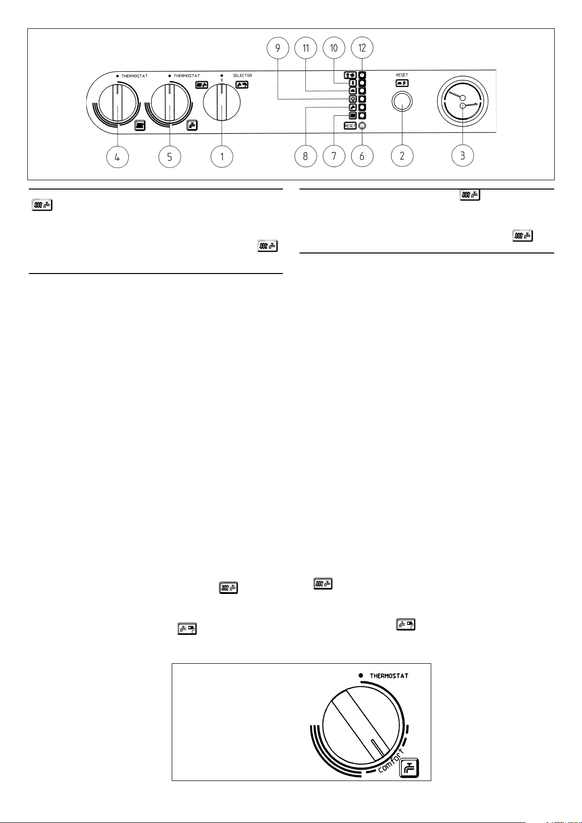
Starting the boiler
Follow these instructions:
1)provide power supply to the boiler;
2)open the gas cock;
3) turn selector switch (1) to set the boiler on Wintertime operation (
or to Summertime operation;
4)turn the central heating temperature adjusting control (4) or the DHW
adjusting control (5) in order to light the main burner;
Turn the control clockwise to increase the temperature and anti-clockwise
to decrease it. The burner will light whenever heating is required. The
pump will run even when the burner is turned off.
Important: During initial lighting the burner may fail to light immediately
and that may cause a 'blockage' of the boiler. That is due to the air contained
in the gas pipework; in that case we recommend you press the reset button
until the gas reaches the burner.
Henvisninger
før installation
Den første start af kedlen skal gennemføres af en fagmand, som skal
kontrollere følgende:
a) At data på typeskiltet svarer til forsyningsnettets data (strøm, vand,
gas).
b) At installationen tager hensyn til gældende forskrifter.
c) At eltilslutningen til lysnettet og jord gennemføres i henhold til
gældende forskrifter.
Hvis disse punkter ikke overholdes kan det medføre tab af garantien. Inden
start skal beskyttelsesfolien fjernes. Hertil må ikke benyttes værktøj eller
slibemateriale, da dette kan ødelægge de lakerede dele.
Start af kedlen
Følg disse anvisninger:
1)Slut strøm til kedlen.
2)Åbn gashanen.
3)Drej vælgeren (1) for at stille kedlen til vinterdrift (
sommerdrift.
)
4)Drej på temperaturkontrollen for varmtvandstemperaturen knap (5)
for at tænde hovedbrænderen.
Temperaturen øges ved at dreje kontrollen med uret, og den mindskes ved
at dreje mod uret. Brænderen vil tænde, når der er behov for opvarmning.
Pumpen fungerer også, når brænderen er slukket.
Vigtigt: Under den første tænding kan det forekomme, at brænderen ikke
tænder straks, og det kan medføre en 'blokering' af kedlen. Det skyldes
luften i gasledningen, og i så fald skal man trykke på reset-knappen, til
gassen når frem til brænderen.
) eller til
4
921.968.2.00.02.010702
Page 5
9803300100
Important: When the selector switch (1) is set on Wintertime operation
(
) it may be necessary to wait some
in the burner’s switching on in the central heating mode. As the boiler is
equipped with a weather-compensating device and outside probe, selector
switch (4) does not have any function.
immediately put the selector switch (1) on (0) and then again on (
There is no waiting time is needed when the boiler is set to the hotwater heating.
minutes because of the time lag
To relight the main burner
Room temperature
adjustment
NUVOLA 28 Fi is equipped with a weather-compensating device and
outside probe.
The boiler temperature / flow temperature is regulated automatically by
the outside temperature and the selected heating curve.
The temperature in the individual rooms can be set by means of the
thermostatic valves on the radiators.
The controls can be expanded by means of a time clock, a remote
control or a room thermostat (accessories). Electronic modulation of the
flame enables the boiler to reach the set temperature by adapting the gas
supply to the burner to the actual heat requirements.
Vigtigt: Når vælgeren (1) stilles på vinterdrift ( ), kan der opstå nogle
minutters ventetid p.g.a. brænderens indkoblinsforsinkelse i centralvarmefunktionen. Da kedlen er udstyret med vejrkompenseringsanlæg og udeføler
har vælgeren (4) ingen funktion. For straks at tænde hovedbrænderen
igen skal man stille vælgeren (1) på (0) og derefter igen på (
).
er ingen ventetid, når kedlen er stillet til varmtvandsopvarmning.
Justering
af rumtemperaturen
NUVOLA 28 Fi er udstyret med vejrkompenseringsanlæg og udeføler.
Kedeltemperaturen/fremløbstemperaturen reguleres automatisk af
udetemperaturen og den valgte varmekurve.
Rumtemperaturen i det enkelte rum indstilles på radiatorernes termostatventiler.
Styringen kan udbygges med tænd/sluk-ur, fjernbetjening eller
rumtermostat (extra udstyr). Elektronisk modulation af flammen gør det
muligt for kedlen at nå op på den indstillede temperatur ved at tilpasse
gasforsyningen til brænderen til det aktuelle varmebehov.
). Der
DHW temperature adjustment
❋ The modulating gas valve is provided with a device to modulate the
flame depending on the value set by knob (5), which adjusts the
temperature of the water contained in the storage cylinder, and on the
quantity of hot water drawn from the taps.
❋ Turn knob (5) which adjusts the temperature of the water contained in
the hot-water cylinder, clockwise to increase the temperature and
anticlockwise to decrease it. When the pre-set temperature is reached
the boiler will automatically switch to the central heating mode if the
selector switch E/I (1) is on Wintertime operation
It is possible to shut off the hot-water mode by placing knob (5) at the
minimum corresponding to the storage cylinder frost protection function.
When the selector switch (1) is placed on
pump will be running only when there is a call for domestic hot water and
the boiler is operating to reach the set
temperature.
To ensure energy saving and
economical management of your
boiler, we recommend you place the
switch adjusting the hot water temperature on "COMFORT" (see drawing).
In wintertime the temperature of the
water will generally be set higher.
the main burner and the
switch adjusting the hot water
temperature on "COMFORT"
Knap til justering af
varmtvandstemperaturen
stillet på "COMFORT"
.
Drifttermostat - brugsvand
❋
Modulationsgasventilen er forsynet med en mekanisme, som modulerer
flammen afhængigt af den værdi, der er indstillet med knappen (5), som
justerer temperaturen på vandet i beholderen, samt af den mængde
varmt vand, der tappes fra hanerne.
❋
Drej knap (5), der justerer temperaturen på vandet i varmtvandsbeholderen, med uret for at øge temperaturen og mod uret for at
mindske den. Når den forudindstillede temperatur nås, skifter kedlen
automatisk til centralvarmefunktion, hvis vælgeren (1) står på vinterdrift
.
Det er muligt at slukke for varmtvands-funktionen ved at stille knap (5) på
den mindste værdi, der svarer til beholderens frostsikringsfunktion.
Når vælgeren (1) stilles på
kun, når der er behov for varmt vand, og kedlen skal være i drift for at
opnå den indstillede temperatur.
, fungerer hovedbrænderen og pumpen
For at opnå energibesparelse og
økonomisk drift af kedlen
anbefales det at stille vælgeren
til justering af
varmtvandstemperaturen på
"COMFORT" (se tegningen).
Om vinteren stilles
varmtvandstemperaturen
normalt højere.
9610080400
5
921.968.2.00.02.010702
Page 6

Filling the boiler
Important: Check the manometer regularly to ensure that the appliance
pressure when cold is between 0.5 and 1 bar.
If the pressure is lower, open the filling tap. We recommend that you
open the taps very slowly, as this has a positive effect on the ventilation.
Vandpåfyldning
Vigtigt: Kontroller regelmæssigt på manometeret, om det kolde anlægstryk
ligger mellem 0,5 og 1 bar.
Er trykket lavere, åbn påfyldningshanen. Det anbefales at åbne hanerne
meget lagsomt, da dette har en positiv indflydelse på udlufningen.
If the pressure falls rapidly, the service firm should be called.
The boiler is fitted with a differential pressure valve, which stops the
boiler operating in the event of a blocked pump or a lack of water.
Safeguard against blockage
of pump and 3-way valve
If the heating system and/or the hot-water supply do not give off heat in
the course of 24 hours, the pump will be automatically switched off for
one minute.
If the heating system and/or the hot-water supply do not give off heat in
the course of 24 hours, the 3-way valve rotates completely.
This function is active if the electricity supply to the boiler is switched
on, and provided that the selector switch (1) is not in position (0).
Boiler temperatures and room
temperature controlled by
Remote Control
(on request)
The boiler can be equipped with a remote control unit. This accessory (on
request) can be installed in rooms up to 50 m (max. cable length allowed)
away from the boiler. With the remote control it is possible to control the
boiler water temperatures (heating system and hot water), the room temperature (night and daytime temperature) and the heating program can be
adjusted (programmable clock is included).
Falder trykket hyppigt, bør der sendes bud efter servicefirmaet.
Keden er udstyret med en differenstrykventil, der ved blokeret pumpe eller
ved vandmangel stopper kedeldriften.
Blokeringsbeskyttelse af
pumpe og 3-vejs-ventil
Hvis varmesystemet og/eller varmtvandsforsyningen i løbet af 24 timer
ikke aftager varme, bliver pumpen automatisk sat i drift i et minut.
Hvis varmesystemet og/eller varmtvandsforsyningen i løbet af 24 timer
ikke aftager varme, gennemfører 3-vejs-ventilen en fuldstændig
omdrejning.
Denne funktion er aktiv, såfremt kedlen forsynes med strøm, og såfremt
omskifteren (1) ikke befinder sig i position (0).
Kedeltemperaturer og
rumtemperatur kontrolleret
med fjernbetjening
(Extraudstyr)
Kedlen kan udstyres med en fjernbetjeningsenhed. Dette ekstraudstyr kan
installeres i rum op til 50 m (maksimal tilladt kabellængde) væk fra kedlen.
Ved hjælp af fjernbetieningen er det muligt at kontrollere kedlens
vandtemperatur (opvarmningssystem og varmtvand), rumtemperaturen
(nat- og dagtemperatur), og man kan indstille opvarmningsprogrammet
(programmerbart ur medfølger).
Important: To select the remote control function it is necessary to set the
knob (1) to position SUMMER (
indicator neon (7 or 8), in case of hot water or heating request, will flash.
The temperature regulating knobs 4 and 5 on the boiler control panel
(picture 1) are not active.
). Under these circumstances the
Turning off the boiler
Totally
❋
turn the selector switch (1) to (0); in this way, you will cut off the
electrical supply to the boiler
❋
close the gas service cock
Partially
❋
turn the selector switch (1) to summertime operation
That will set the switch which adjusts the temperature of the water in the
hot-water cylinder to hot water mode and the boiler will thus automatically
switch to that function.
.
Vigtigt: Til valg af fjernbetjeningsfunktionen skal man stille knappen (1)
på positionen SOMMER ( ). Under disse forhold vil
indikatorlamperne (7 eller 8), i tilfælde af behov for varmtvand eller
opvarmning, lyseblinke. Temperaturreguleringsknapperne 4 og 5 på
kedlens kontrolpanel (billede 1) er inaktive.
Slukning af kedlen
Fuldstændigt
❋
Drej vælgeren (1) til (0), på den måde afbrydes strømforsyningen til
kedlen
❋
Luk for gashanen
Delvist
❋
Drej vælgeren (1) til sommerdrift
Dette vil indstille den kontakt, der justerer temperaturen på vandet i
varmtvandsbeholderen, til varmtvands-funktion, og kedlen vil automatisk
skifte til denne funktion.
.
6
921.968.2.00.02.010702
Page 7
Prolonged standstill of the
Længerevarende nedlukning
system. Danger of frost
We recommend you avoid draining the whole system as replacing the
water leads to pointless and harmful limescale deposits inside the boiler
and on the heat exchangers.
In case the boiler is not operated during wintertime and is therefore
exposed to danger of frost we suggest you add some specific-purpose
anti-freeze to the water contained in the system (e.g.: propylene glycole
coupled with corrosion and scaling inhibitors).
The electronic management of BAXI boilers includes a 'frost protection'
function in the central heating system which operates the burner until it
reaches a flow temperature of 30° C when the temperature in the system
falls below 5°C.
The frost protection function is activated if:
* electrical supply to the boiler is on;
* the selector switch (1) is not on (0);
* the gas service cock is open;
* the system pressure corresponds to the required pressure;
* the boiler has not been put out of operation.
As far as the hot water cylinder is concerned the following may occur:
❋ if the knob that adjusts the temperature of the water in the cylinder is
set on min. the boiler will automatically light when the temperature in
the hot-water cylinder falls below 5°C. In that case ensure that there
is in fact an electricity and gas supply to the boiler
❋ it is possible to completely empty the cylinder by opening the drain
plug under the cylinder and a hot water tap as close as possible to the
boiler (remember catch the water in a bucket or for discarge (60 l), see
page 26).
af systemet. Fare for frost
Det anbefales, at man undgår at tømme hele systemet, da en udskiftning
af vandet vil medføre formålsløse og skadelige kalkaflejringer indvendigt
i kedlen og på varmevekslerne.
I tilfælde af at kedlen ikke er i drift om vinteren og således er udsat for
frostfare, anbefales det, at man tilsætter en særlig frostvæske til vandet i
systemet (f.eks. propylenglykol sammen med additiver til hæmning af
korrosion og afskalning).
Den elektroniske styring af BAXI kedler omfatter en
"frostsikringsfunktion" i centralvarmesystemet, der holder brænderen i
gang, til den når en flowtemperatur på 30
falder til under 5
Frostsikringssystemet aktiveres, hvis:
* strømforsyningen til kedlen er tændt,
* vælgeren (1) ikke står på (0),
* gashanen er åben,
* anlœggets tryk svarer til det krœvede tryk,
* kedlen ikke er sat ud af drift.
Med hensyn til varmtvandsbeholderen kan følgende ske:
❋
Hvis knappen, der justerer temperaturen på vandet i beholderen,
stilles på min., vil kedlen automatisk starte, når temperaturen i
varmtvandsbeholderen falder til under 5
at der faktisk er el- og gasforsyning til kedlen.
❋
Det er muligt helt at tømme beholderen ved at åbne aftapningsproppen
under beholderen og en varmtvandshane så tæt på kedlen som muligt
(husk at opsamle vandet i spand eller til afløb (60 l) se side 26.
°
C.
°
C, når temperaturen i anlœgget
°
C. I så fald skal man sikre,
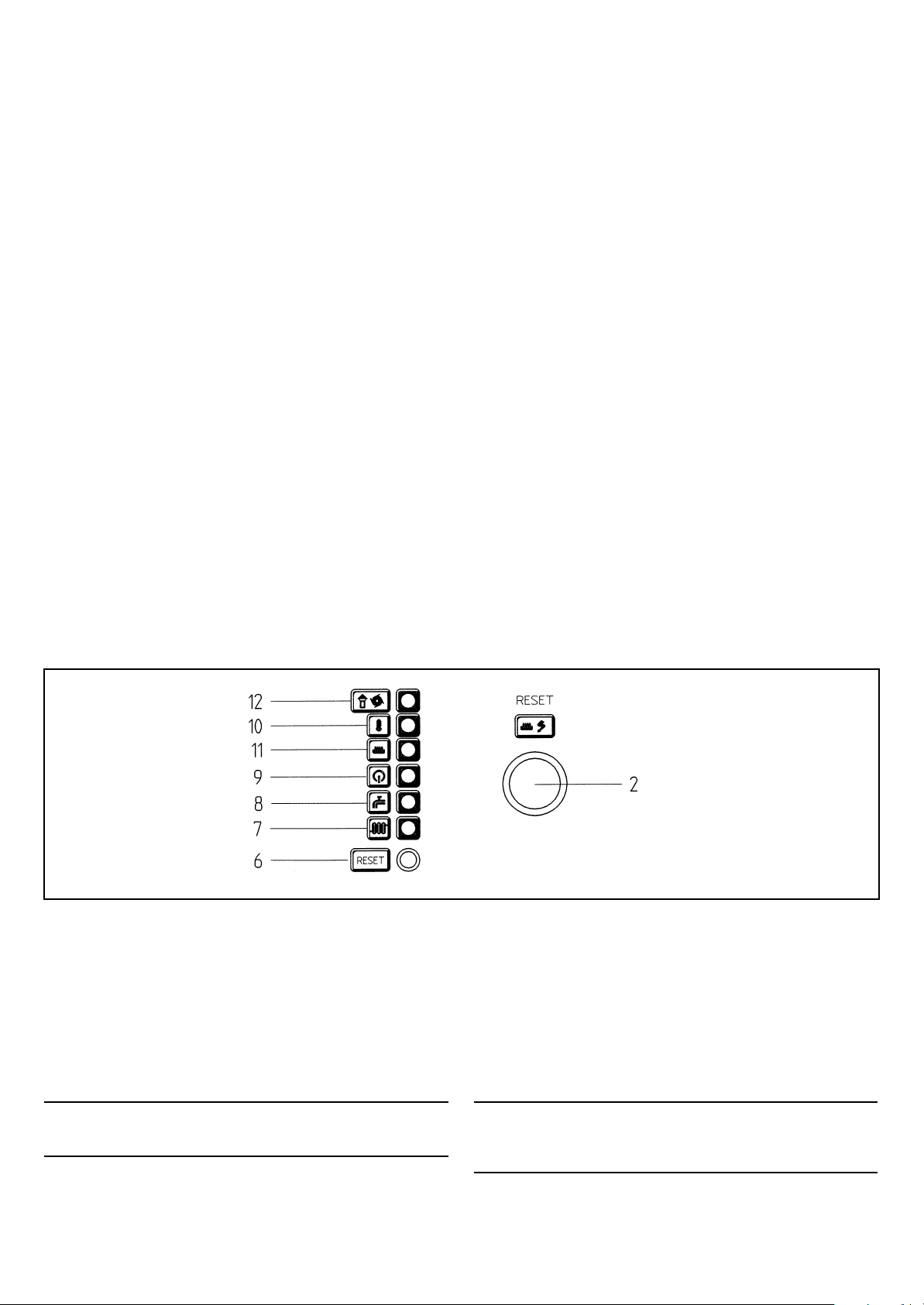
Boiler indicator neons,
resetting, and fault
monitoring
2 lack of gas / reset button
6 overheat thermostat reset
button
7 indicator for operation of
heat to the radiator citcuit
8 indicator for operation of the
hot-water cylinder
9 electrical supply is on
10 overheat thermostat has cut
out
11 flame indicator (burner on)
12 blocked flue indicator
The blocked flue indicator neon (12) is switched on by an air monitor in
case:
• either the flue or the flue terminal are partially or totally obstructed
• the venturi is obstructed
• the fan is blocked
• the connection between the venturi and air monitor is interrupted.
Under the above mentioned circumstances the boiler will switch to standby and only after the causes of the fault have been removed will it
automatically resume regular operations.
Kedlens indikatorlamper,
genindkobling
og fejlkontrol
2 gasmangel / reset-knap
6 reset-knap til
overophedningstermostaten
7 indikator for drift af varme til
radiatorkredsen
8 indikator for drift af varmtvands
beholderen
9 elforsyningen er tændt
10 overkogstermostaten er koblet ud.
11 flammeindikator (brænder tændt)
12 indikator for blokeret aftræk
9803300200
Indikatorlampen for blokeret aftræk (12) aktiveres af en luftvagt i tilfælde
af:
• at enten aftrækket eller terminalen er helt eller delvist blokeret
• at venturirørene er blokerede
• at ventilatoren er blokeret
• at forbindelsen mellem venturirør og luftvagt er afbrudt.
Under ovennævnte omstændigheder vil kedlen skifte til stand-by, og først
når årsagerne til fejlen er fjernet, vil den automatisk genoptage normal
drift.
Note: during lighting of the boiler the indicator neon (12) will be on while
the air monitor is checking that the fan is correctly working. The neon will
stay on permanently if it detects any of the faults described above.
The indicator neon (10) will be switched on by the overheat thermostat
when the boiler temperature is too high.
921.968.2.00.02.010702
Bemærk: Under tændingen af kedlen vil indikatorlampen (12) være tændt,
mens luftvagt kontrollerer, om blæseren fungerer korrekt. Kontrollampen
vil være tændt permanent, hvis den registrerer nogle af de ovennævnte
fejltilstande.
Indikatorlampen (10) aktiveres af overkogstermostaten, når
kedeltemperaturen er for høj.
7
Page 8

In these cases the boiler will be stopped (consequently the indicator neon
(10) will be permanently on).
After the cause of the fault has been removed press the reset button (6) and
check the value shown on the pressure gauge (3) (see section Filling the
boiler on page 6).
I disse tilfælde stoppes kedlen (og dermed vil indikatorlampen (10) være
tændt permanent).
Efter at årsagen til fejlen er fjernet, skal man trykke på reset-knappen (6)
og kontrollere værdien vist på trykmåleren (3) (se afsnittet vandpåfyldning
af kedlen på side 6).
The overheat thermostat and the air monitor must not be deactivated.
It will not be possible to restart the boiler if either the flue thermostat or
the overheat thermostat are still on.
The indicator neon (2) will be switched on by a flame sensing electrode in
case of lack of gas or incomplete lighting of the main burner.
In these cases the boiler will be blocked as a safety measure.
To resume normal operations, press the rest button (2).
Should these safety functions be activated frequently, the boiler should be
checked by a Qualified Service Engineer.
Gas change
Your boiler is
Any gas change must be carried out by a Qualified Service Engineer.
designed to be operated either with natural gas or with LPG.
Servicing instructions
To maintain efficient and safe operation of your boiler, it should be serviced
every 2 years by a Qualified Gas-Service Engineer.
Careful servicing will ensure economical operation of the system.
Do not clean the outer casing of the appliance with abrasive, aggressive
and/or easily flammable cleaners (i.e.: gasoline, alcohol, and so on). Always
disconnect the electrical supply to the appliance before cleaning it (see
section Turning off the boiler on page 6).
Overkogstermostaten og luftvagten må ikke sœttes ud af funktion
Genindkobling af kedlen er ikke mulig, hvis enten luftvagten eller
overkogstermostaten er afbrudt.
Indikatorlampen (2) aktiveres af en flammefølerelektrode i tilfælde af
mangel på gas eller en ufuldstændig tænding af hovedbrænderen.
I disse tilfælde sker der en sikkerhedsblokering af kedlen.
Tryk på reset-knappen (2) for at genoptage normal drift.
Hvis disse sikkerhedsfunktioner aktiveres ofte, skal kedlen synes af en
autoriseret servicetekniker.
Gasskift
Kedlen er beregnet til at fungere enten med naturgas eller
Ethvert gasskifte skal foretages af en autoriseret servicetekniker.
flaskegas (LPG).
Vedligeholdelsesvejledning
For at kunne sikre en effektiv og sikker drift bør kedlen have service
eftersyn hvert 2. år. af autoriseret gasservicetekniker.
Omhyggelig vedligeholdelse sikrer økonomisk drift af systemet.
Ydersiden på apparatet må ikke rengøres med slibende, aggressive og/
eller letantændelige rengøringsmidler (f.eks: rensebenzin, alkohol osv.).
Afbryd altid elforsyningen til apparatet, før der foretages nogen form for
rengøring (se afsnittet Slukning af kedlen på side 6).
8
921.968.2.00.02.010702
Page 9
INSTRUCTIONS PERTAINING
VEJLEDNING TIL
TO THE INSTALLER
General information
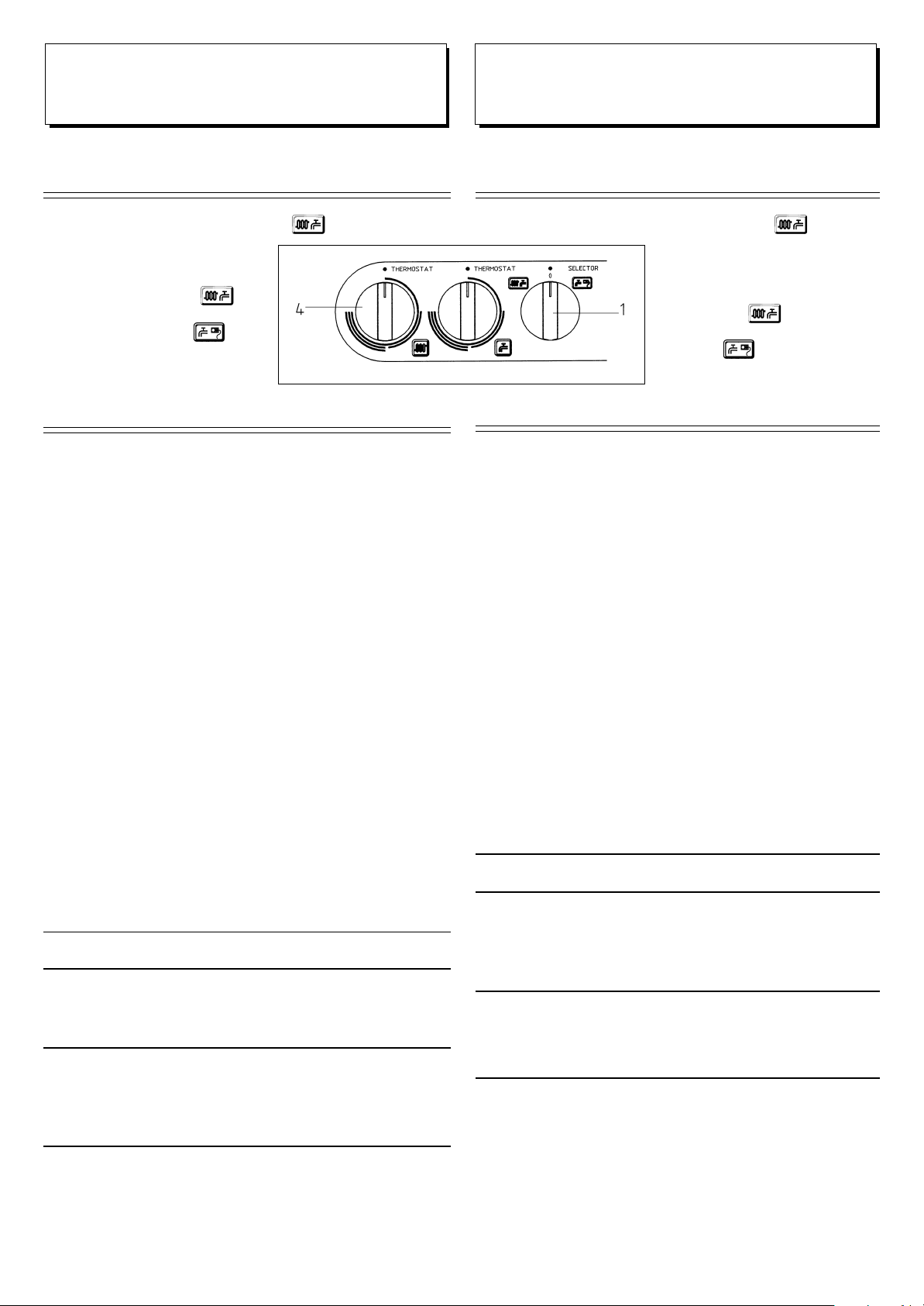
Warning: If the selector switch (1) is set on ( ) there will be a wait of
a few minutes each time the burner is
started. To get the burner to start
immediately, selector switch (1) can be
set to (0) and then again on ( ). This
waiting time does not occur if the selector
switch (1) is set to the (
symbol
.
The following explanations and technical instructions are addressed to
installers
and are intended to help ensure a faultless installation.
• The boiler must be installed, adjusted and started for the first time by an
approved specialist.
The gas supply company’s regulations, as well as the local building
regulations, must be observed (The Gas Regulations and the Building
Regulations)
• The boiler can be connected to any type of heating surfaces, radiators
or convectors, in both single and double pipe systems. The pipe
diameters must be calculated in the normal way, taking into account the
characteristics of the available heating surfaces, as well as the water
quantities and pump pressure indicated on page 31.
• To ensure satisfactory and safe operation of the boiler, we recommend
that the boiler be checked every other year by an authorised servicing
firm.
• Packaging (plastic bags, polystyrene, etc.) must not be left within
children’s reach as they are a potential source of danger.
) DHW
Instructions prior
to installation
The boiler heats water to a temperature below boiling point at normal air
pressure. It must be connected to a heating system which corresponds to
its characteristics and output. The following operations must be carried
out before installation of the boiler:
a) All of the appliance’s pipes must be flushed out to remove any threading
and welding deposits and also any remains of solvent
INSTALLATØREN
Almene anvisninger
Vigtigt: Hvis omskifteren (1) befinder sig i position ( ), vil der ved
enhver start af brænderen opstå en
ventetid på nogle minutter. For at opnå,
at brænderen starter med det samme, kan
omskifteren (1) stilles på (0) og derefter
igen tilbage til (
opstår ikke, hvis omskifteren (1) er
indstillet på
9803300300
De følgende forklaringer og tekniske vejledninger henvender sig til
installatøren og skal medvirke til en perfekt installation.
• Installation, indstilling og første start af kedlen må kun gennemføres
af en godkendt fagmand.
Gasforsyningsselskabets forskrifter, såsom de lokale byggeregler,
skal overholdes (Gasreglementet og Bygningsreglementet).
• Kedlen kan bruges med enhver art varmeflader, radiator eller konvektor
såvel i 1-strengs- som i 2-strengs anlæg. Rørenes diameter skal
beregnes på normal måde, hvorved de forhåndenværende varmefladers
egenskaber, såvel som de på side 31 anførte vandmængder og pumpetryk
tilgodeses.
• For at sikre en upåklagelig og sikker drift af kedlen anbefales det, at
kedlen hvert andet år bliver kontrolleret af et autoriseret servicefirma.
• Emballage (plastikposer, polystyrol osv.) må ikke være tilgængelig for
børn, da det repræsenterer en potentiel farekilde.
). Denne ventetid
DHW-symbol.
Anvisninger før installation
Kedlen opvarmer vand til en temperatur under kogepunktet ved alm.
lufttryk. Den skal tilsluttes et varmesystem, der svarer til dens egenskaber
og ydelse. Inden installation af kedlen skal følgende gennemføres:
a) Alle anlæggets rørledninger skal skylles for at fjerne gevind- og
svejserester, samt rester af opløsningsmidler.
b) Det skal kontrolleres, om kedlen er beregnet til drift med den til
rådighed stående gasart. Dette kan aflæses af påskriften på emballagen
og af kedlens typeskilt.
b) Check that the boiler is intended for operation with the type of gas
available. This can be read from the inscriptions on the packaging and
from the rating plate on the boiler.
c) The boiler may be installed in a cupboard, the corner of a room and wall
rececesses etc., provided that a minimum clearance of 20 mm is
maintained between the boilder and the fixed side-wall. In addition,
allowance must be made for the required height for installation of the
flue system and also for any servicing or cleaning of dirt collectors
below the boiler.
d) The boiler is usually very quiet, but the pump and fan may be annoying.
Account should be taken of any noise nuisance from the boiler when it
is installed next to or in a living room. The best position will be on an
external wall or other heavy wall. The wall must be able to bear the
weight of the boiler with water and pipes etc.
921.968.2.00.02.010702
c) Kedlen kan indbygges i skabe, rumhjørner og murnicher m.v., såfremt
der holdes en afstand på min. 20 mm mellem kedlen og faste sidevægge.
Der skal endvidere tages hensyn til fornøden højde til montering af
aftrækssystemet samt eventuel betjening og rensning af snavsamler
under kedlen.
d) Kedlen er normalt meget støjsvag, men pumpe og ventilator kan dog
virke generende. Der bør tages højde for eventuelle støjgener fra
kedlen, når den opsættes op til eller i et beboelsesrum. Bedste placering
vil være på en ydervæg eller anden tung væg. Væggen skal kunne bære
vægten af kedlen med vandindhold og rør m.v.
9
Page 10
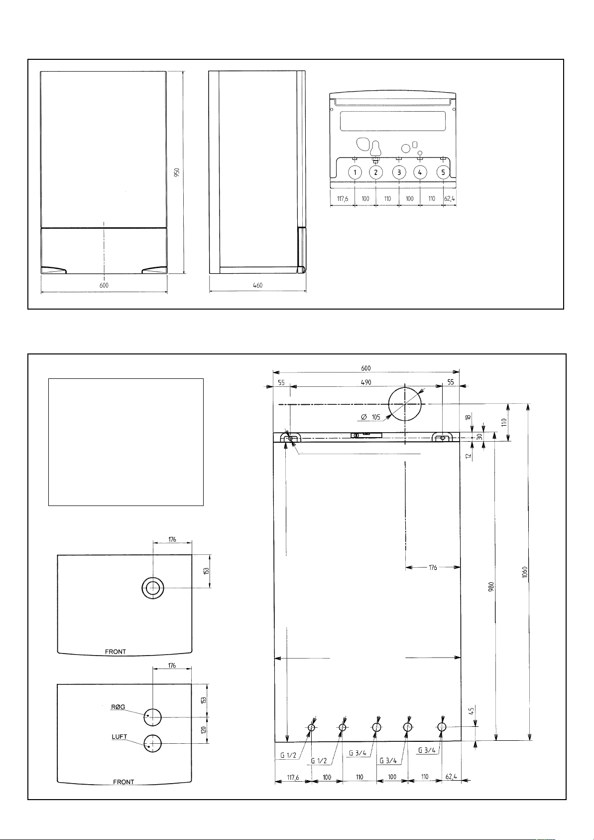
Boiler size
Kedelstørrelse
9803230402
Template size
Note:
The 105 mm diameter hole for the
horizontal balanced flue.
Bemærk:
Hullet på 105 mm i diameter til
vandret balanceret aftrœk.
1 - Domestic hot water - G 1/2
2 - Domestic cold water - G 1/2
3 - Radiator return - G 3/4
4 - Radiator flow - G 3/4
5 - Gas connection - 3/4
1 - Varmt brugsvand - G 1/2
2 - Kold brugsvand - G 1/2
3 - Radiator retur - G 3/4
4 - Radiator fremløb - G 3/4
5 - Gastilslutning - 3/4
Skabelonstørrelse
drill 12 mm mounting holes
12 mm huller ophængning udbores
Connection of balanced flue –
horizontal and vertical
Tilslutning af aftræk balanceret
vandret oglodret
Connection of split flue
Tilslutning af split aftræk
Height 950 mm
Højde 950 mm
10
921.968.2.00.02.010702
Vertical centre line for horizontal
Width 600 mm
Bredde 600 mm
balanceret aftræk
Lodret akse for vandret
coaxial flue and air duct
0006190300
Page 11
Mounting of the boiler
First determine the precise place for locating it. Drill holes according to
the template. Then fix the boiler to the wall using the Rawlplugs and
screws provided.
The first step in installing the appliance is to connect the water and gas
pipes at the bottom of the boiler.
If the boiler is intended to replace an existing appliance, we recommend
that a filter be incorporated to collect the deposits and scum which may be
circulating even after cleaning.
After the boiler has been mounted on the wall, connect the flue / air intake
which goes with it, as described in the introduction in the next section.
Note: Central heating system: we
recommend thatyou have cut-off cocks
installed on the central heating system flow
and return.
FLUE OPTIONS AND DISTANCE
REQUIREMENTS
Various flue options
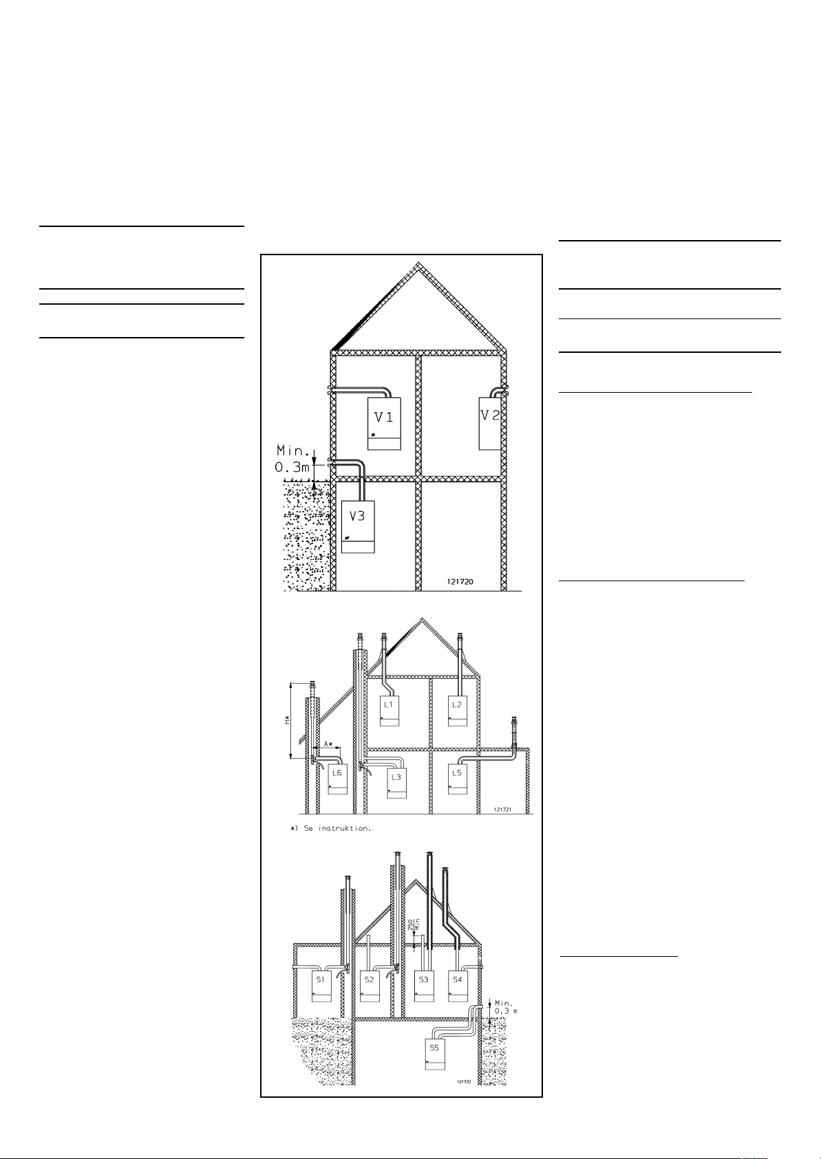
Horizontal balanced flue (V1 to V3)
The accompanying diagrams show a house
where all options for a horizontal balanced
flue are shown.
Maximum length of the flue is 2770 mm
+ 1 bend
V1 Horizontal balanced flue on either left
or right side
V2 Horizontal balanced flue at the back
V3 “Horizontal” balanced flue at a differ-
ent height from the boiler flue.
(max. 1 90° bend)
Vertical balanced flue (L1 to L6)
The accompanying diagrams show a house
where all options for a vertical balanced
flue are shown.
Maximum length with double pipe is 6.5 m.
Each 90° bend reduces the length by 1 m
- 45° bend reduces the length by 0.5 m
L1 Vertical balanced flue with 2x 45°
bends inserted for parallel displace-
ment
L2 Vertical balanced flue
L3 Balanced flue via existing disused
chimney, where the air is taken out
from the chimney via the flue pipe.
Maximum length (air + flue gas) is 20 m.
Each 90° bend reduces the length by 1 m
Min. diameter of chimney is 130 mm.
L3 This shows the pipe layout with the
boiler to the right of the chimney
L5 Vertical balanced flue with 2x 90°
bends inserted
L6 Vertical balanced flue with double pipe
from boiler to disused chimney, where
the air is taken out from the chimney
via the flue pipe.
Split flue (S1 to S5)
The accompanying diagrams show all the
options with split flue.
Maximum total length (air + flue gas) is
20 m.
Each 90° bend reduces the length by 1 m
- 45° bend reduces the length by 0.5 m
Min. chimney diameter is 130 mm.
S1 Air from external wall-flue pipe taken
via the chimney
Maximum total length (air + flue gas)
is (10 + 10 m).
921.968.2.00.02.010702
Opstilling af kedlen
Først fastlægges det nøjagtige sted for opstillingen. Bor huller efter
skabelonen. Derefter fastgøres kedlen til væggen med de rawlplugs og
skruer, der er vedlagt.
Installation af anlægget starter med tilslutning af vand- og gasledninger
forneden på kedlen.
Skal kedlen skiftes ud i bestående anlæg anbefales det, at der indbygges
et filter, der kan opfange de aflejringer og slagger, der også efter rensningen
kan komme i omløb.
Efter at kedlen er monteret på væggen, gennemføres tilslutningen af de
tilhørende røgaftræk / luftindtag som beskrevet i indledningen i det
efterfølgende kapitel.
Bemœrk: Centralvarmesystemet: Det
anbefales, at man installerer stopventiler på
centralvarmesystemet flow- og returledninger.
AFTRÆKS MULIGHEDER OG
AFSTANDSKRAV
Forskellige aftræks muligheder
Vandret balanceret aftræk (V1 til V3)
Hosstående er vist et hus, hvor alle
mulighederne med vandret balanceret aftræk
er vist.
Maksimal længde af aftræk er 2770 mm + 1
bøjning
V1 Vandret balanceret aftræk til enten venstre
eller højre side
V2 Vandret balanceret aftræk bagud
V3 “Vandret” balanceret aftræk til anden
0005250100
0005250200
0005250300
11
højde end kedlens aftræk. (maks 1 stk 90
bøjning)
Lodret balanceret aftræk (L1 til L6)
Hosstående er vist et hus, hvor alle muligheder
med lodret balanceret aftræk er vist.
Maksimal længde med dobbeltrør er 6,5 m.
Hver 90
-45° bøjning reducerer længden med 0,5
L1 Lodret balanceret aftræk med indskudt
L2 Lodret balanceret aftræk
L3 Balanceret aftræk via eksisterende
L3 Her vist rørføring med kedlen til højre
L5 Lodret balanceret aftræk med indskudt
L6 Lodret balanceret aftræk med
Split aftræk (S1 til S5)
Hosstående er alle mulighederne med split
aftræk vist.
Maksimal samlet længde (luft+røggas) er 20 m.
Hver 90° bøjning reducerer længden med 1 m
- 45° bøjning reducerer længden med 0,5 m
S1 Luft fra ydervæg-røggasrør ført gennem
°
bøjning reducerer længden med 1 m
m
2 stk 45
°
bøjning for parallelforskydning
afmeldt skorsten, hvor luften tages fra
skorstenen uden om aftræksrøret.
Maksimal længde (luft+røggas) er 20 m
Hver 90
med 1 m
Min. diameter på skorstenen er 130 mm
for skorsten
2 stk 90
dobbeltrør fra kedel til afmeldt skorsten,
hvor luften tages fra skorstenen uden
om aftræksrøret
Min. skorstens diameter er 130 mm
skorsten
Maksimal samlet længde (luft+røggas)
er (10 + 10m).
°
bøjning reducerer længden
°
bøjning
°
Page 12
S2 Air from unused loft of at least 70m3, flue pipe taken via the chimney
Maximum total length (air + flue gas) is (10 + 10 m).
S3 Air from unused loft of at least 70m
3
, flue pipe taken vertically above
the roof
S4 Air from external wall-flue pipe taken vertically above the roof
S5 Horizontal split with air and flue pipe taken side by side to an external
wall.
NOTE: The air intake must be taken from the open air or from a ventilated
loft of at least 70 m
3
.
S2 Luft fra uudnyttet tagrum på mindst 70 m3, røggasrør ført gennem
skorsten
Maksimal samlet længde (luft+røggas) er (10 + 10m).
S3 Luft fra uudnyttet tagrum på mindst 70 m3, røggasrør ført lodret over
tag.
S4 Luft fra ydervæg-røggasrør ført lodret over tag.
S5 Vandret split med luft- og røggasrør ført ved siden af hinanden til
ydervæg.
OBS! Luftindtag skal tages fra det fri eller fra ventileret loftrum min. 70 m
3
See following pages for additional data.
DISTANCE REQUIREMENTS – AIR INTAKE / FLUE OUTLET
It is necessary to comply with the Gas Regulations concerning
distances from woodwork and meter cupboards etc.
BALANCED FLUE – HORIZONTAL or VERTICAL DOUBLE PIPE
There are no distance requirements from external double pipe to woodwork
(for flue solution L3, see distance requirements for split solution).
In addition, the following distance requirements must be observed:
HORIZONTAL – positioning of air intake / flue outlet
Min. distance (mm)
From vertical outlet pipe 75
From internal or external corners 500
From wall opposite (facing the air intake / flue outlet) 2000
From another air intake / flue outlet opposite 1200
Vertically from another air intake / flue outlet on the same wall 500
Horizontally from another air intake / flue outlet on the same wall 500
Yderligere data se følgende sider.
AFSTANDSKRAV - LUFTINDTAG/RØGAFGANG
Man skal rette sig efter Gasreglementets krav vedr. afstande til træværk
og måleskabe etc.
BALANCERET AFTRÆK - VANDRET eller LODRET DOBBELTRØR
Der er ingen afstandskrav fra udv. dobbeltrør til træværk. (Ved
aftræksløsning L3 se afstandskrav til splitløsning)
Desuden skal følgende afstandskrav respekteres:
VANDRET - Placering af luftindtag/røgafgang
Min. afstand (mm)
Fra lodrette afløbsrør 75
Fra indvendige eller udvendige hjørner 500
Fra væg overfor (imod luftindtaget/røgafgangen) 2000
Fra anden luftindtag/røgafgang overfor 1200
Lodret fra anden luftindtag/røgafgang på samme væg 500
Vandret fra anden luftindtag/røgafgang på samme væg 500
VERTICAL - positioning of air intake / flue outlet
Vertical above the roof surface with the following distance
requirements: Min. distance (mm)
Distance measured perpendicular to the roof surface 300
Distance to vertical wall (chimney) 500
Height above chimney (with pipe taken through the chimney) 300
Height above flat roof 750
SPLIT FLUE – distance requirements
Where indicated by the conditions, a split flue may be used, i.e. air intake
and flue pipe are each carried in its own pipe. Bends and pipes should be
ordered in accordance with the local conditions, but they are subject to
the following limitations:
Max. total length of the split flue (air pipe + flue pipe) = 20 m minus 1 m
for each 90° bend – (2 x 45° bends = 1 x 90° bend).
Distance requirements from flammable materials and insulation
The distance from flammable materials must be as laid down in the Gas
Regulations regarding flue ducts (section 5.5). These say among other
things: On all sides, there must be a distance of at least 50 mm from the
outer edge of the flue pipe to flammable materials. The flue pipe
MUST
be insulated with a minimum of 25 mm mineral wool from and including
the first floor, up to and including the end above the roof.
In addition, the following distance requirements must be observed:
SPLIT FLUE – HORIZONTAL or VERTICAL
Positioning of air intake
Min. distance (mm)
Height above ground 300
Vertically and horizontally from another balanced flue 800
Horizontally from regulator cabinet 200
Vertically from regulator cabinet 1000
From ventilation opening 500
921.968.2.00.02.010702
LODRET - Placering af luftindtag/røgafgang
Lodret over tagflade med følgende afstandskrav:
Min. afstand (mm)
Afstand målt vinkelret på tagfladen. 300
Afstand til lodret væg (skorsten) 500
Højde over skorsten (med rør ført gennem skorsten) 300
Højde over fladt tag 750
SPLITAFTRÆK - Afstandskrav
Hvor forholdene taler for det kan der bruges splitaftræk, dvs. luftindtag
og røgrør føres i hvert sit rør. Bøjninger og rør bestilles efter de stedlige
forhold, der er dog den begrænsning at:
Max. totallængde af splitaftræk (Luftrør + røgrør) = 20 m minus 1 m for
hver 90
°
bøjning - (2 stk 45° = 1x90° bøjning)
Afstandskrav til brændbart matr. og isolering.
Afstand til brændbart matr. skal være som Gasreglementet foreskriver vedr.
aftrækskanal (afsnit 5.5) Det vil bl.a. sige:
Der skal overalt være en afstand på mindst 50 mm fra yderkant røgrør til
brændbart materiale.
Aftræksrøret
SKAL isoleres med min. 25 mm mineraluld fra og med første
etageadskillelse til og med afslutning over tag.
Desuden skal følgende afstandskrav respekteres:
SPLITAFTRÆK VANDRET eller LODRET
Placering af luftindtag Min. afstand (mm)
Højde over terræn 300
Lodret og vandret fra andet balanceret aftræk 800
Vandret fra regulatorskab 200
Lodret fra regulatorskab 1000
Til ventilationsåbning 500
12
Page 13

Positioning of air intake in a loft:
The volume of the loft
must be a minimum of 70m3 and must be ventilated,
and it must be an unused part of the residence. The fresh air intake must
end at least 0.25 m above the insulation material.
Placering af luftindtag i tagrum:
Tagrummets volumen
skal være min. 70 m3 og fornødent ventileret, og
skal udgøre en uudnyttet del af boligen. Friskluftsindtaget skal afsluttes
min 0,25 m. over isoleringsmaterialet.
SPLIT FLUE VERTICAL Positioning of flue above the roof
Vertical above the roof surface with the following distance criteria:
Min. distance (mm)
Distance measured perpendicular to the roof surface 300
From ventilation openings or other balanced flue 800
Height above chimney (with pipe taken through the chimney) 300
SPLIT FLUE HORIZONTAL
Positioning of horizontal split (flue outlet and air intake side by side)
Same distance requirements as positioning of air intake.
Secure the pipe carefully and insulate where necessary.
AIR INTAKE / FLUE OUTLET –
HORIZONTAL DOUBLE PIPE (V1, V2 AND V3 SYSTEM)
The HORIZONTAL connecting set consists of:
1 bend Ø 60 / Ø 100
1 clamp
In addition, a flue duct pack must be used, consisting of:
1 wall grill m Ø 100 pipe L = 625 mm or 2700 mm
1 flue pipe Ø 63 L = 700 mm or 2770 mm
1 wall plate
4 Rawlplugs 6x30
4 screws 4.2 x 32
1 cover plate 140x132 / opening Ø 100 mm
1 set of instructions for fitting the cover plate
SPLITAFTRÆK LODRET Placering af røgaftræk over tag
lodret over tagflade med følgende afstandskrav: Min. afstand (mm)
Afstand målt vinkelret på tagfladen. 300
Til ventilationsåbninger el. andre balancerede aftræk. 800
Højde over skorsten (med rør ført gennem skorsten) 300
SPLITAFTRÆK VANDRET
Placering af vandret split (røgaftræk og luftindtag ved siden af hinanden)
Samme afstandskrav som placering af luftindtag.
Rør fastgøres omhyggeligt og isoleres hvor nødvendigt.
LUFTINDTAG/RØGAFGANG -
VANDRET DOBBELTRØR (SYSTEM V1, V2 OG V3)
VANDRET Tilslutningssæt består af:
1 stk. bøjning Ø60/Ø100
1 stk. spændbånd
Desuden skal bruges en pakke med aftrækskanal som består af:
1 stk. murgril m Ø100 rør L=625 mm eller 2700 mm.
1 stk røgrør Ø63 L=700 mm eller 2770 mm.
1 stk. murplade
4 stk. rawlplug 6x30
4 stk. skrue 4,2 x 32
1 stk dækplade 140x132/hul Ø100
1 stk instruktion for montage af dækplade
Air intake / flue outlet – HORIZONTAL fitting – follow the numbers
1. Unpack the boiler and horizontal connecting set (bend), and read the
instructions.
2. Hang the boiler in position
3. The bend is positioned at the top of the boiler over the flue / air
connecting piece and keep in position by means of the enclosed clamp.
4. From the centre of the bend (Ø 60 / Ø 100) for the air intake / flue outlet,
draw a line towards the wall where the pipe is to exit. There must be fall
of at least 5‰ outwards (away from the boiler) i.e. 5 mm in 1000 mm.
5. Make a Ø 107-110 hole in the wall.
6. Measure the distance from the contact point (in the bend) to the outer
side of the wall (wall plate) – mark out the direct length measurement
on the pipe.
7. The reduction must be made at (A) on the external pipe – see diagram
below.
8. The internal pipe is shortened at (A) by the same amount; i.e. if the
external pipe is cut by 10 cm for example, then the internal pipe must
be also shortened by 10 cm at (A) (the internal pipe will be 75 mm longer
than the external pipe).
010720_0100
Luftindtag/røgafgang - VANDRET Montage - følg numrene
1. Pak kedel og vandret tilslutningssæt (bøjning) ud, og læs instruktionerne.
2. Hæng kedlen på plads.
3. Bøjningen placeres på kedlens top over røg-/luftstuds og holdes på
plads med medsendte spændbånd.
4. Fra midten af bøjning (Ø60/Ø100) for luftindtag/røgafgang tegnes en
streg hen på væggen hvor røret skal gå ud. Der skal være min. 5
promille fald udad (bort fra kedlen), dvs. 5 mm på 1000 mm.
5. Lav et Ø107-110 mm hul i væggen
6. Mål afstand fra anlægspunkt (i bøjning) til udv. side af mur (murplade)
- afsæt det direkte længdemål på røret.
7. Afkortning skal ske ved (A) på udv. rør - se tegn. nedenfor.
8. Indv. rør afkortes ved (A) med samme stykke.
dvs: Hvis der skæres f.eks. 10 cm af udv. rør så skal indv. rør også
afkortes med 10 cm ved (A) (indv. rør vil være 75 mm længere end udv.
rør).
010720_0200
Clamp
Spændebånd
Air / flue connecting piece
Luft-/røgstuds
13
921.968.2.00.02.010702
Fit this end into the horizontal
connecting set (bend!)
Denne ende monteres i vandret
tilslutningssæt (bøjning)!
Page 14

9. Assemble the pipes and push
them into the bend. Ensure that
the pipe with the grill is turned
so that it projects neatly.
10. Seal the opening around the pipe
on the internal wall.
11. Attach wall plates over the pipe
outside (if the opening fits exactly, there is no need to use a
Clamp
Spændebård
wall plate).
12. Mark up the openings.
13. Remove the plate, drill openings, insert Rawlplugs (protect
the end of the pipe against dirt
from the drilling).
14. Remove cover which was used
to prevent dirt. Attach wall plate
and screw it tight.
Vertical displacement – V3
System
1. If you wish to have a vertical
Clamp
Spændebård
Transition piece must face with the ‘thick’
end at the bottom!
Overgangslykke skal vende med den
"tykke" ende nederst!
displacement, this must be inserted between the bend and the
boiler.
2. The internal pipe for “vertical
displacement” must be shortened at the end opposite the “point”.
3. The supplied set includes 2 transition pieces – pop rivets must not be
used with them.
VERTICAL BALANCED FLUE (L1, L2 AND L5 SYSTEM)
Where indicated by the conditions, use a VERTICAL balanced flue, which
means that the air is taken in and the flue gas is directed out at the same
place VERTICALLY above the roof.
The maximum length of the flue system is 7.5 m (minus 0.5 m per 45°
bend, minus 1 m per 90° bend).
The VERTICAL connecting set consists of:
1 connecting set Ø 60 / Ø 100 - Ø 100 / Ø 125
In addition, the following must be used:
1 ceiling flange for the end against the ceiling
1 roof duct with cover
A number of double pipes L=1000 or L=500
1 roof flashing 5-25° or 25-45°
If necessary
1 set of elbow pieces (2) - 45° for L1 system or
2 elbow pieces 90° for L5 system
(if necessary, “top section for the chimney” as flashing
for flat roof = 091631)
Air intake / flue outlet – VERTICAL
• Put the connecting set for vertical outlet on the
boiler’s flue outlet.
• Make the opening through the ceiling and roof
(protect the connecting set from getting dirty)
• Measure the pipe length and shorten it.
• If a parallel displacement of the vertical balanced
flue system is necessary, do this by inserting 2 x
45° elbow pieces as shown (if necessary, 2 x 90°
bends).
• If necessary, a pipe section must be inserted
between the elbow pieces in order to achieve an
adequate displacement.
• Fit the pipe through the roof and ceiling.
NB. Remember the ceiling flange.
• Fit the roof flashing. Note: The black side on the
“Roof duct with cover” must go against the “tilting flange” on the roof flashing.
• Secure the pipe to the roof structure.
• Point the roof flashing with silicone.
921.968.2.00.02.010702
9. Rørene samles og presses ind i
bøjningen.
Tilse at røret med gril er drejet så
det ser pænt ud.
10. Tæt hullet omkring røret på den
indvendige væg.
The internal pipe must be shortened at the
end opposite ‘point’!
Afkortning af inderrør skal ske i ende modsat
"spids" !
11. Anbring murplader over røret
udvendig (Hvis hullet passer nøjagtigt
er det unødvendigt at anvende
murplade)
12. Mærk hullerne op
13. Fjern pladen, bor huller, sæt
rawlplugs i (beskyt enden af røret mod
snavs fra boringen).
14. Fjern afdækning der blev anbragt
for at hindre snavs. Anbring murplade
og skru den fast.
010720_0300
Lodret forskydning System V3
1. Hvis der ønskes en lodret
forskydning så indskydes denne
mellem bøjning og kedel
2. Afkortning af inderrør til “lodret
forskydning” skal ske i ende modsat
„spids“.
3. I sættet medleveres 2
overgangsstykker – der skal kun bruges
det uden popnitter.
LODRET BALANCERET AFTRÆK (SYSTEM L1, L2 og L5)
Hvor forholdene taler herfor anvendes LODRET balanceret aftrækhvorved forstås at luften tages ind og røggas ledes ud samme sted LODRET
over tag.
Aftrækssystemets max. længde er 7,5 m. (minus 0,5 m pr 45° bøjning,
minus 1 m pr 90
°
bøjning)
LODRET Tilslutningssæt består af:
1 stk. Tilslutningssæt Ø60/100 - Ø80/125
Desuden skal bruges:
1 stk. loftskrave for afslutning mod loft.
1 stk. taggennemføring m. hætte
Et antal dobbeltrør L=1000 eller L=500
1 stk. Taginddækning 5-25
°
eller 25-45
°
evt.
°
1 sæt knærør (2 stk.) - 45
2 stk knærør 90
til system L1 eller
°
til system L5
(evt. “topstykke for skorsten” som inddækning for fladt tag = 091631)
Luftindtag/røgafgang - LODRET
• Tilslutningssæt for lodret aftræk
placeres på kedlens røgafgang.
Roof duct with cover
Taggennemføring m/hætte
Roof flashing (5-25°) (25-45°)
Taginddækning (5-25°) (25-45°)
• Hullet igennem loft og tag
laves (beskyt kedlen mod
tilsnavsning).
• Rørlængde opmåles og
afkortes.
• Hvis det er nødvendigt at
parallelforskyde det lodret
balancerede aftrækssystem gøres
dette ved at indskyde 2 stk. 45
knærør som vist. (Evt. 2 stk. 90
45° elbow piece (set of 2)
45° knærør (sæt med 2 stk)
Ceiling flange
Loftskrave
Double pipe L = 1000 (L = 500)
Dobbeltrør L = 1000 (L = 500)
Vertical connecting set
Lodret tilslutningssæt
bøjninger).
• Mellem knærørene skal
evt. indskydes et rørstykke for at
opnå tilstrækkelig forskydning
• Rør monteres gennem tag
og loft.
NB. Husk loftkrave.
• Monter taginddækning
Bemærk:
Den sorte kant på
“Taggennemføring m. hætte”
skal gå imod “vippekraven” på
taginddækningen
• Rør fastgøres til
tagkonstruktion.
010720_0400
• Taginddækning fuges med
silikone.
14
°
°
Page 15

• Secure the “tilting flange” to the roof flashing with the screws pro-
vided.
• Fit the ceiling flange.
The total length of the flue must not exceed 7.5 m from connecting unit to
the roof cover.
NB! There are no distance requirements from the external pipe to the
woodwork with the L1, L2, L5 and L6 system
VERTICAL BALANCED FLUE WITH AIR FROM EXISTING
DISUSED CHIMNEY
L6 System
Where indicated by the conditions, use the aforementioned VERTICAL
balanced flue – which means that the air is taken in via a disused existing
chimney and the flue gas is directed out at the same place (through the
cover (for balanced vertical flue), which allows the air to go down through
an existing disused chimney).
• “Vippekraven” på taginddækningen sikres med de medleverede skruer.
• Loftkrave monteres
Den totale længde på aftrækket må ikke overstige 7,5 m fra koblingsunit
til taghætten.
NB! Der er ingen afstandskrav fra udvendig rør til træværk ved system
L1, L2, L5 og L6.
LODRET BALANCERET AFTRÆK MED LUFT FRA
EKSISTERENDE AFMELDT SKORSTEN
System L6
Hvor forholdene taler herfor anvendes ovennævnte LODRET balanceret
aftræk - hvorved forstås at luften tages ind via afmeldt eksisterende skorsten
og røggas ledes ud samme sted (Gennem hætte (for balanceret lodret
aftræk) der lader luften gå ned gennem skorstenen).
Tilslutningssæt lodret via skorsten består af:
The vertical connecting set via the chimney consists of:
1 vertical connecting set Ø 60/100 – Ø 80/125
In addition, the following must be used:
• 1 roof duct with cover
• 1 cap for the chimney
• Double pipe Ø 80/125 L = 500- or 1000 mm
• 90° bend Ø 80/125
• Straight pipe for flue gas (a rust-resistant pipe must be used for flue gas)
• 90° bend, Ø 80, rust-resistant for flue gas
• If necessary, condensation trap
• Silicone
Maximum length of flue – see table on next page.
Installation of vertical balanced flue, where the existing disused
chimney is used to carry the flue pipe and to convey air
NB: With flue lengths over 3 metres in the chimney, we recommend
fitting of a condensation trap.
In the case of installation in a disused
chimney, a servicing / cleaning door must
be fitted in the chimney jamb, allowing
dismantling of the float in the lower part for
cleaning / servicing.
Roof duct with cover
Taggennemføring m/hætte
Cap for chimney
Top til skorsten
• The chimney must be disused and must
be cleaned very carefully in order to
prevent dirt being sucked into the gas
boiler.
Pipe Ø80 (rust-resistant)
Rør Ø80 (rustfri)
• Minimum diameter of the chimney Ø
130
• Maximum length of flue – see table on
the next page.
1. Use silicone or similar for a water-tight
joint.
2. Screw the cap for the chimney securely
on top of the chimney.
3. Fit the flue pipes to the “roof duct with
Condensation trap
Kondensfang
Double pipe 500 or 1000 mm
Dobbeltrør 500 eller 1000 mm
cover”, and lower all of the pipes into the
chimney. (If necessary, secure the joints
with self-tapping, rust-resistant screws
or pop rivets (not provided).)
4. The pipe is taken from the flue pipe in
the chimney to the boiler
1 stk. Lodret tilslutningssæt Ø60/100 - Ø80/125
Desuden skal bruges:
• 1 stk. taggennemføring m. hætte
• 1 stk. Top til skorsten
• Dobbeltrør ø80/125 L=500- eller 1000 mm
• Bøjning 90
°
ø80/125
• Lige rør til røggas (Til røggas skal anvendes rustfri rør)
• Bøjning 90
°
ø80 rustfri til røggas
• evt. kondensfang
• Silikone
Max længde af aftræk - se tabel næste side.
Montage af lodret balanceret aftræk, hvor den eksisterende afmeldte
skorsten anvendes til føring af røggasrør og til lufttransport.
NB: Ved aftrækslængde over 3 meter i skorstenen anbefales installation
af kondensfang
Ved montage i afmeldt skorsten
skal der i skorstensvangen
etableres en service-/
renselem, der muliggør
afmontering af svømmeren i
underparten for rensning/
service.
• Skorstenen skal være afmeldt
og skal være renset meget
omhyggeligt for at undgå, at
der suges snavs ind i
gaskedlen.
• Minimum diameter af skorsten
Ø 130
• Max længde af aftræk - se
tabel næste side.
1. Benyt silikone el. lign. for
vandtæt samling.
2. Topstykket skrues forsvarligt
90° bend (Ø80/125)
Bøjning 90° (Ø80/125)
Vertical connecting set
Split tilslutningssæt
på top af skorsten.
3. Røgaftræksrørene monteres
på “taggennemføring m.
hætte”, og alle rørene sænkes
ned i skorstenen. (Samlingerne
sikres evt. med selvskærende
rustfri skruer eller popnitter
(medfølger ikke))
4. Rør føres fra røgaftræksrør i
skorsten til kedel.
010723_0100
15
921.968.2.00.02.010702
Page 16

As there is a certain loss of pressure in the double pipe A, the table indicates
the maximum height (H) in relation to the length of (A).
A (m) 0 - 1 1 - 2 2 - 3
H max. (m) 15 12 9
010723_0200
Condensation trap
Kondensfang
Da der er et vist tryktab i dobbeltrøret A er der i tabellen anført maksimal
højde (H) i forhold til længden af (A)
A (m) 0 - 1 1 - 2 2 - 3
H max. (m) 15 12 9
FITTING OF A SPLIT CONNECTING SET TO Ø80 MM PIPE
✱ If the total flue-air ducts length
exceeds 12 metres, remove the
restrictor and washer provided
with the boiler.
✱ Hvis den samlede røggas-
luftkanallængde overstiger 12
meter, skal man fjerne den ene
pakning og flowbegrænseren
leveret med kedlen.
MONTAGE AF SPLITTILSLUTNINGSSÆT TIL Ø80 MM RØR
Silicone washer
In the following examples, the split connecting set must be fitted on the
boiler as shown on the next page.
921.968.2.00.02.010702
00060200300
På de efterfølgende eksempler skal split tilslutningssættet monteres på
kedlen som vist herover.
16
Page 17

VERTICAL BALANCED FLUE WITH AIR FROM
EXISTING DISUSED CHIMNEY
LODRET BALANCERET AFTRÆK MED LUFT FRA
EKSISTERENDE AFMELDT SKORSTEN
L 3 System
Where indicated by the conditions, use the aforementioned VERTICAL
balanced flue – which means that the air is taken in via an existing disused
chimney and the flue gas is directed out at the same place (through the
cover (for the balanced vertical flue) which allows the air to go down
through an existing chimney).
The connecting set for flue/air via a chimney consists of:
1 top section for the chimney
1 roof duct with cover
1 split connecting set Ø 80.
In addition, the following must be used:
• Straight pipe Ø 80 for air or flue gas (use a rust-resistant pipe for flue
gas, an aluminium pipe for air)
• Maximum total length of air + flue = (10 + 10) m minus 1 m for each
90° bend (0.5 m for each 45° bend)
• 15°, 30°, 45° or 90° bend (use rust-resistant for flue gas, aluminium for
air)
• Wall bushes
• If necessary, pipe clamps for flue pipe and air pipe
• Silicone
• If necessary, condensation trap
Installation of vertical balanced flue, where the existing disused
chimney is used to carry the flue gas pipe and to convey air
System L3
Hvor forholdene taler herfor anvendes ovennævnte LODRET balanceret
aftræk - hvorved forstås at luften tages ind via afmeldt eksisterende afmeldt
skorsten og røggas ledes ud samme sted (Gennem hætte (for balanceret
lodret aftræk) der lader luften gå ned gennem en eksisterende, afmeldt
skorsten).
Tilslutningssæt aftræk/luft via skorsten består af:
1 stk. Topstykke til skorsten.
1 stk. Taggennemføring m. hætte.
1 stk. Split tilslutningssæt Ø80.
Desuden skal bruges:
• Lige rør Ø80 til luft eller røggas (Til røggas skal anvendes rustfri, til
luft anvendes aluminiumsrør)
• Max totallængde af luft+aftræk = (10+10) m minus 1 m for hver 90
bøjning (0,5 m pr. 45° bøjning)
• Bøjning 15
°
, 30°, 45° eller 90° (Til røggas skal anvendes rustfri, til luft
anvendes aluminiumsrør)
• Murbøsninger
• Evt. rørbærer for røgrør og luftrør
• Silikone
• Evt. kondensfang
Montage af lodret balanceret aftræk, hvor den eksisterende afmeldte
skorsten anvendes til føring af røggasrør og til lufttransport.
°
• The chimney must be disused and must be
cleaned very carefully in order to prevent
dirt being sucked into the gas boiler.
• Minimum diameter of the chimney Ø 130
• Maximum total length of air + flue = (10 +
10) m minus 1 m for each 90° bend (0.5 m
Roof duct with cover
Taggennemføring m/hætte
Cap for chimney
Top til skorsten
for each 45° bend)
1. Use silicone or similar for a water-tight
joint.
2. Screw the top section securely on top of the
Pipe Ø80 (rust-resistant)
Rør Ø80 (rustfri)
chimney.
3. Fit the flue pipes to the “roof duct with
cover”, and lower all of the pipes into the
chimney. (If necessary, secure the joints
with self-tapping, rust-resistant screws or
pop rivets (not provided).)
4. Attach the split connecting set to the boiler
as shown elsewhere in these instructions.
90° bend Ø80 (rust-resistant)
Bøjning 90° Ø80 (rustfri)
Wall bushes
Murbøsninger
5. The pipe is taken from the flue pipe in the
chimney to the boiler
6. Air intake is taken to the chimney either
above or below the flue outlet.
7. The air intake must be secured so that it
cannot be moved, thereby restricting the air
intake in the chimney and boiler.
Distance from flammable materials must be
as laid down in the Gas Regulations
regarding a flue duct (section 5.5), that is to say:
• On all sides there must be a clearance of at least 50 mm from the outer
edge of the flue pipe to flammable materials.
• The flue pipe MUST be insulated with a minimum of 25 mm mineral
wool* from and including the first wall duct up to and including the
end.
• The mineral wool insulation must be taken through the flammable
material and, if necessary, end at least 100 mm from it.
• Skorstenen skal være afmeldt og
skal være renset meget omhyggeligt
for at undgå, at der suges snavs ind i
gaskedlen.
• Minimum diameter af skorsten Ø
130
• Max totallængde af luft+aftræk =
(10 + 10) m minus 1 m for hver 90
bøjning (0,5 m pr. 45° bøjning)
1. Benyt silikone el. lign. for vandtæt
samling.
2. Topstykket skrues forsvarligt på top
af skorsten.
3. Røgaftræksrørene monteres på
“taggennemføring m. hætte”, og alle
rørene sænkes ned i skorstenen.
(Samlingerne sikres evt. med
selvskærende rustfri skruer eller
Vertical connecting set
Split tilslutningssæt
popnitter (medfølger ikke)
4. Split tilslutningssættet monteres på
kedlen som anført andetsteds i denne
instruktion.
5. Rør føres fra røgaftræksrør i
skorsten til kedel.
6. Luftindtag føres til skorsten, enten
over eller under røgafgang.
010723_0300
7. Luftindtaget skal sikres, så det ikke
kan flyttes og derved begrænse
luftindtag i skorsten og kedel.
Afstand til brændbart matr. skal være som Gasreglementet foreskriver
vedr. aftrækskanal (afsnit 5.5) Det vil bl.a. sige:
• Der skal overalt være en afstand på mindst 50 mm fra yderkant røgrør
til brændbart materiale.
• Aftræksrøret SKAL isoleres med min. 25 mm mineraluld* fra og med
første murgennemføring til og med afslutning.
• Mineraluldsisoleringen skal føres med igennem brændbart matr. og
°
17
921.968.2.00.02.010702
Page 18

• “Horizontal” flue pipes must be installed with a fall of at least a 5 ‰
towards the condensation trap.
NOTE: There
are criteria for the distance from an external flue pipe to
flammable materials.
evt. slutte min. 100 mm herfra.
• “Vandrette” aftræksrør skal føres med min. 5 promille fald mod
kondensfanget.
OBS: Der
er afstandskrav fra udvendig aftræksrør til brændbart matr.
* 25 mm mineral wool insulation is not supplied by BAXI.
NB:With flue lengths over 3 metres in the chimney, we recommend fitting
of a condensation trap.
In the case of installation in a disused chimney, a servicing / cleaning
door must be fitted in the chimney jamb, allowing dismantling of the
float in the lower part for cleaning / servicing.
SPLIT FLUE IN CONNECTION WITH EXISTING
DISUSED CHIMNEY
S1 and S2 System
Where indicated by the conditions, use the SPLIT flue, which means that
the air is taken in via one pipe and the flue gas is directed out above a
chimney / roof in another pipe.
The connecting set for “flue/air via a chimney” consists of:
1 connecting set Ø 80
In addition, the following must be used:
• Air intake and cover
• Cap for the chimney
• Straight pipe for air or flue gas (use a rust-resistant pipe for flue gas, an
aluminium pipe for air)
• Maximum total length of split flue = (10 + 10) m minus 1 m for each
90° bend (0.5 m for each 45° bend)
• 15°, 30°, 45° or 90° bend (use a rust-resistant pipe for flue gas, an
aluminium pipe for air)
• Silicone
• If necessary, pipe clamps for flue pipe and air pipe
• If necessary, ceiling flange Ø 80
• If necessary, condensation trap
Installation of SPLIT in a typical chimney
Insulated flue pipe with cover
• Fit the split connecting set to the boiler as
shown elsewhere in these instructions.
Air intake (Use an aluminium pipe for air)
S
: Secure air grating to the outside of the wall
1
using the Rawlplugs and rust-resistant
Isoleret røggasrør m/hætte
Cap for chimney
Pipe Ø80 (rust-resistant)
Top til skorsten
Rør Ø80 (rustfri)
screws provided. If necessary, seal around the
grating with silicone.
S
: Air from an unused loft of at least 70 m3.
2
Use the air grating provided on the top of
the pipe.
Flue (A rust-resistant pipe must be used for flue
gas.)
The chimney must be disused and
must be very
Silicone
Silicone
Wall grating
Murrist
Bend (Alu.)
Bøjning (Alu.)
carefully cleaned.
Minimum diameter of chimney Ø 130
Maximum total length of the split flue = (10 + 10)
m minus 1m for each 90° bend (0.5 m for each
45° bend)
010723_0400
• Use silicone or similar for a water-tight joint
• Screw the top section securely on top of the
chimney.
• Attach the flue outlet pipes to the top insulated flue pipe with cover, and
then lower all of the pipes into the chimney. (If necessary, secure the
joints with self-tapping, rust-resistant screws or pop rivets (not provided).)
• Mount the drip edge on the “Insulated flue pipe with cover”
• The pipe is taken from the flue outlet pipe in the chimney to the boiler.
• 25 mm mineraluldsisolering medleveres ikke fra BAXI.
NB: Ved aftrækslængde over 3 meter i skorstenen anbefales installation
af kondensfang
Ved montage i afmeldt skorsten skal der i skorstensvangen etableres
en service-/renselem, der muliggør afmontering af svømmeren i
underparten for rensning/service.
SPLIT AFTRÆK I FORBINDELSE MED EKSISTERENDE
AFMELDT SKORSTEN
System S1 og S2
Hvor forholdene taler herfor anvendes SPLIT aftræk hvorved forstås at
luften tages ind i et rør og røggas ledes ud over skorsten/tag i et andet.
Tilslutningssæt til “Aftræk/luft via skorsten” består af:
1 stk. tilslutningssæt Ø80
Desuden skal bruges:
• Luftindtag og hætte
• Top til skorsten
• Lige rør til luft eller røggas (Til røggas skal anvendes rustfri rør, til luft
anvendes aluminiumsrør)
• Max totallængde af splitaftræk = (10+10)m minus 1 m for hver 90
bøjning (0,5 m pr. 45° bøjning)
• Bøjning 15º, 30º, 45° eller 90° (Til røggas skal anvendes rustfri rør, til
luft anvendes aluminiumsrør)
• Silikone
• Evt. rørbærer for røgrør og luftrør
• Evt. loftkrave Ø80
• Evt. kondensfang.
Montage af SPLIT i eks. skorsten
• Split tilslutningssættet monteres
Drip edge
Drypkont
på kedlen som anført andetsteds i denne
instruktion.
Luftindtag (Til luft anvendes
aluminiumsrør)
S
: Luftrist fastgøres med de med flg.
1
rawlplug og rustfri skruer udvendig på
mur. Der tætnes evt. omkring rist med
silikone.
S
: Luft fra uudnyttet tagrum på min.
2
3
70 m
90° bend Ø80 (rust-resistant)
Bøjning 90° Ø80 (rustfri)
Condensation trap
Kondensfang
Wall bushes
Murbøsninger
Pipe Ø 80 (Alu.)
Rør Ø 80 (Alu.)
Vertical connecting set
Split tilslutningssæt
. Medflg. luftrist anvendes ovenpå
røret.
Røgaftræk (Til røggas skal anvendes
rustfri rør)
Skorstenen skal være afmeldt og
renset meget omhyggeligt.
Minimum diameter af skorsten Ø 130
Max totallængde af splitaftræk =
(10+10)m minus 1 m for hver 90
(0,5 m pr. 45
°
bøjning)
• Benyt silikone el. lign. for vandtæt samling.
• Topstykket skrues forsvarligt på top af skorsten.
• Røgaftræksrørene monteres på øverste isolerede røggasrør m. hætte,
hvorefter alle rørene sænkes ned i skorstenen. (Samlingerne sikres evt.
med selvskærende rustfri skruer eller popnitter (medfølger ikke))
• Drypkant spændes på “Isoleret røggasrør m/hætte”
• Rør føres fra røgaftræksrør i skorsten til kedel.
skal være
°
bøjning
°
18
921.968.2.00.02.010702
Page 19

Distance from flammable materials must be as laid down in the Gas
Regulations regarding a flue duct (section 5.5), that is to say:
• On all sides there must be a clearance of at least 50 mm from the outer
edge of the flue pipe to flammable materials.
• The flue pipe
MUST be insulated with a minimum of 25 mm mineral
wool* from and including the first wall duct up to and including the
end.
• The mineral wool insulation must be taken through the flammable
material and, if necessary, end at least 100 mm from it.
• “Horizontal” flue pipes must be installed with a fall of at least a 5‰
towards the boiler or towards the condensation trap.
• The “horizontal” air intake pipe next to the wall grating must have a fall
of at least 5‰ outwards – away from the boiler.
NOTE: There
are criteria for the distance from an external flue pipe to
flammable materials.
• 25 mm mineral wool insulation is not supplied by BAXI.
NB:With flue lengths over 3 metres in the chimney, we recommend fitting
of a condensation trap. In the case of installation in a disused chimney,
a servicing / cleaning door must be fitted in the chimney jamb, allowing
dismantling of the float in the lower part for cleaning / servicing.
Afstand til brændbart matr. skal være som Gasreglementet foreskriver
vedr. aftrækskanal (afsnit 5.5) Det vil bl.a. sige:
• Der skal overalt være en afstand på mindst 50 mm fra yderkant røgrør
til brændbart materiale.
• Aftræksrøret
SKAL isoleres med min. 25 mm mineraluld* fra og med
første murgennemføring til og med afslutning.
• Mineraluldsisoleringen skal føres med igennem brændbart matr. og
evt. slutte min. 100 mm herfra.
• “Vandrette” aftræksrør skal føres med min. 5 promille fald mod kedel
eller mod kondensfang.
• Det “vandrette” luftindtagsrør nærmest murrist skal føres med min. 5
promille fald udad - bort fra kedlen.
OBS: Der
er afstandskrav fra udvendig aftræksrør til brændbart matr.
• 25 mm mineraluldsisolering medleveres ikke fra BAXI.
NB: Ved aftrækslængde over 3 meter i skorstenen anbefales installation
af kondensfang
Ved montage i afmeldt skorsten skal der i skorstensvangen etableres
en service-/renselem, der muliggør afmontering af svømmeren i
underparten for rensning/service.
SPLIT FLUE WITH FLUE OUTLET VIA THE ROOF
S3 and S4 System
Where indicated by the conditions, use the SPLIT flue, which means that
the air is taken in via one pipe and the flue gas is directed out above the
roof in another pipe.
The connecting set consists of:
1 connecting set Ø 80
In addition, the following must be used:
• Air intake and cover
• Cap for the chimney
• Straight pipe for air or flue gas (use a rust-resistant pipe for flue gas, an
aluminium pipe for air)
• Maximum total length of split flue = 20 m minus 1 m for each 90° bend
(0.5 m for each 45° bend)
• 45° or 90° bend (use rust-resistant for flue gas, aluminium for air)
• Silicone
• Pipe clamps for flue pipe and air pipe
• Ceiling flange for end against the ceiling
• 1 roof flashing
Installation of vertical SPLIT
• Fit the split connecting set to the boiler
as shown elsewhere in these instructions.
NB:The air intake must be taken from the
open air or from a ventilated loft of at
least 70 m
3
.
Air intake / flue outlet – SPLIT
SPLIT AFTRÆK MED RØGAFTRÆK OVER TAG
System S3 og S4
Hvor forholdene taler herfor anvendes SPLIT aftræk hvorved forstås at
luften tages ind i et rør og røggas ledes ud over tag i et andet.
Tilslutningssæt består af:
1 stk. tilslutningssæt Ø80
Desuden skal bruges:
• Luftindtag og hætte
• Top til skorsten
• Lige rør til luft eller røggas (Til røggas skal anvendes rustfri rør, til luft
anvendes aluminiumsrør)
• Max totallængde af splitaftræk = 20 m minus 1 m for hver 90
(0,5 m pr. 45
°
bøjning)
°
bøjning
• Bøjning 45° eller 90° (Til røggas anvendes rustfri, til luft anvendes
aluminium)
• Silikone
• Rørbærer for røgrør og luftrør
• Loftskrave for afslutning mod loft.
• 1 stk. Taginddækning
Montage af lodret SPLIT
Insulated flue pipe with cover
Isoleret røggasrør m/hætte
Roof flashing
Taginddækning
25 mm insulation
* Aluminium laminated mat
Isolering 25 mm
* Alu. Lamelmåtte
• Split tilslutningssættet monteres
på kedlen som anført andetsteds i
denne instruktion.
NB: Luftindtag skal tages fra det fri
eller fra ventileret loftrum på min.
3
70 m
.
Luftindtag/røgafgang - SPLIT
Air intake(Use aluminium for air)
S
: Secure air grating to the outside of the
4
wall using the Rawlplugs and rust-resistant screws provided. If necessary, seal
around the grating with silicone.
S
: Air from an unused loft of at least 70 m3.
3
Use the air grating provided on top of the
pipe.
1. Take the air pipe installation from the air
grating to the air intake of the boiler.
Wall bush
Murbøsning
Silicone
Silicone
Wall grating
Murrist
19
921.968.2.00.02.010702
Ceiling flange
Loftskrave
Pipe Ø80 (rust-resistant)
Rør Ø80 (rustfri)
Vertical connecting set
Split tilslutningssæt
Pipe Ø 80 (Alu.)
Rør Ø 80 (Alu.)
Luftindtag (Til luft anvendes
aluminiumsrør)
S
: Luftrist fastgøres med de med
4
flg. rawlplug og rustfri skruer
udvendig på mur. Der tætnes evt.
omkring rist med silikone.
S
: Luft fra uudnyttet tagrum på
3
min. 70m3 . Medflg. luftrist
anvendes ovenpå røret.
1. Luftrørsinstallationen føres fra
luftrist til kedlens luftindtag.
010725_0100
Page 20

Flue outlet (A rust-resistant pipe must be used for flue gas)
2. The flue outlet starts from the flue-outlet connecting piece with either
a bend or a straight pipe section.
Distance from flammable materials must be as laid down in the Gas
Regulations regarding a flue duct (section 5.5), that is to say:
• On all sides there must be clearance of at least 50 mm from the outer
edge of the flue pipe to flammable materials.
• The flue pipe MUST be insulated with a minimum of 25 mm mineral
wool* from and including the first wall duct up to and including the end.
• The mineral wool insulation must be taken through the flammable
material and, if necessary, end at least 100 mm from it.
• In the case of long flues, we also recommend insulation of the flue
against condensation.
• “Horizontal” flue pipes must be installed with a fall of at least a 5‰
towards the boiler.
• The “horizontal” air intake pipe next to the wall grating must have a fall
of at least 5‰ outwards – away from the boiler.
NOTE: There
are criteria for the distance from external flue pipes to
flammable materials.
• 25 mm mineral wool insulation is not supplied by BAXI.
HORIZONTAL SPLIT FLUE WITH AIR INTAKE AND
FLUE OUTLET THROUGH AN EXTERNAL WALL
Røgaftræk (Til røggas skal anvendes rustfri rør)
2. Røgaftrækket starter fra røgafgangstuden med enten en bøjning eller
et lige rørstykke.
Afstand til brændbart matr. skal være som Gasreglementet foreskriver
vedr. aftrækskanal (afsnit 5.5) Det vil bl.a. sige:
• Der skal overalt være en afstand på mindst 50 mm fra yderkant røgrør
til brændbart materiale.
• Aftræksrøret
SKAL isoleres med min. 25 mm mineraluld* fra og med
første murgennemføring til og med afslutning.
• Mineraluldsisoleringen skal føres med igennem brændbart matr. og
evt. slutte min. 100 mm herfra.
• Ved lange aftræk anbefales desuden isolering af aftrækket mod kondens.
• “Vandrette” aftræksrør skal føres med min. 5 promille fald mod kedel.
• Det “vandrette” luftindtagsrør nærmest murrist skal føres med min. 5
promille fald udad - væk fra kedlen.
OBS: Der
er afstandskrav fra udvendig aftræksrør til brændbart matr.
• 25 mm mineraluldsisolering medleveres ikke fra BAXI.
VANDRET SPLIT AFTRÆK MED LUFTINDTAG OG
RØGAFTRÆK GENNEM YDERMUR
System S5
System S5
Where indicated by the conditions, use the SPLIT flue, which means that
the air is taken in via one pipe and the flue gas is directed out through a
wall in another pipe.
The connecting set consists of:
1 split connecting set Ø 80
1 double wall duct with screen
1 screen for air intake
screws and Rawlplugs for fitting.
In addition, the following must be used:
• Straight pipe for air or flue gas (use a rust-resistant pipe for flue gas, an
aluminium pipe for air).
• Maximum total length of split flue = 20 m minus 1 m for each 90° bend
(0.5 m for each 45° bend)
• 15°, 30°, 45° or 90° bend (maximum 6 bends of 90°) (use a rust-
resistant pipe for flue gas, an aluminium pipe for air)
• Ceiling flange for end against the ceiling/wall
• Pipe clamps for flue pipe and air pipe
• If necessary, wall bushes
Installation of air intake / flue outlet – HORIZONTAL SPLIT
• Fit the split connecting set to the boiler as
shown elsewhere in these instructions.
• The air-pipe installation starts from here.
We recommend that they be insulated
Silicone
Silicone
against condensation.
• The installation sequence – start from the
boiler or from the wall duct, as you wish.
For example, you may start by “installing”
the wall duct attached to a straight pipe
section, then lay the pipes from the boiler,
which is connected in this way to the wall
duct (which is detached at the joint).
• The wall duct must be installed horizon-
tally, i.e. the two “pipes” must be
side by
side. The air intake may be on the right or
on the left, as you wish.
• REMEMBER, if necessary, to transfer the
screen to the air intake – it
must be fitted
over the air intake.
• The flue starts from the flue-outlet con-
necting piece on the boiler with either a
bend or a straight pipe section.
• The air pipe must be insulated against
condensation, as required.
• The flue pipe must be insulated against fire
hazards and condensation.
Flue gas
Røg
Air
Luft
• The flue must be installed in accordance
with the rules laid down in the Gas Regu-
Hvor forholdene taler herfor anvendes SPLIT aftræk hvorved forstås at
luften tages ind i et rør og røggas ledes ud gennem væg i et andet.
Tilslutningssæt består af:
1 stk. split tilslutningssæt Ø80
1 stk. dobbelt murgennemføring m/net
1 stk. skærm for luftindtag
skruer og rawlplugs for montage.
Desuden skal bruges:
• Lige rør til luft eller røggas (Til røggas skal anvendes rustfri rør, til luft
anvendes aluminiumsrør)
• Max totallængde af splitaftræk = 20 m minus 1 m for hver 90
°
(0,5 m pr. 45
• Bøjning 15º, 30º, 45
bøjning)
°
eller 90° (Max 6 bøjninger a 90°) (Til røggas skal
anvendes rustfri rør, til luft anvendes aluminiumsrør)
• Loftskrave for afslutning mod loft/væg.
• Rørbærer for røgrør og luftrør
• Evt. murbøsninger
Montage af luftindtag/røgafgang - VANDRET SPLIT
• Split tilslutningssættet monteres
på kedlen som anført andetsteds i
denne instruktion.
• Herfra starter
Wall bushes
Murbøsninger
Ceiling flange
Loftskrave
Split connection
Split tilslutning
*) If necessary,
Condensation trap
*) EVT.
Kondensfang
luftrørsinstallationen. Det
anbefales at isolere mod kondens.
• Monteringsrækkefølgen - om man
starter fra kedlen eller fra
murgennemføringen er valgfri. Man
kan f.eks. starte med at “montere”
murgennemføringen påsat et lige
rørstykke, derefter oplægges rørene
fra kedlen som så samles med
murgennemføringen (der løsnes ved
samlingen)
• Murgennemføringen skal
Seen from the front
Set for fra
monteres vandret dvs. de to “rør”
skal være
ved siden af hinanden. Det
er valgfri om luftindtag er til højre
Pipe Ø80 (rust-resistant)
Rør Ø80 (rustfri)
eller til venstre.
• HUSK. evt. at flytte skærmen over
luftindtaget - den
skal monteres over
luftindtaget.
Pipe Ø 80 (aluminium)
Rør Ø 80 (Alu.)
• Røgaftrækket starter fra kedlens
røgafgangs studs med enten en
bøjning eller et lige rørstykke.
Seen from above
Set fra oven
• Luftrøret skal isoleres mod
010725_0200
kondens efter behov.
°
bøjning
20
921.968.2.00.02.010702
Page 21

lations.
Distance from flammable materials must be as laid down in the Gas
Regulations regarding a flue duct (section 5.5), that is to say:
• On all sides there must be clearance of at least 50 mm from the outer
edge of the flue pipe to flammable materials.
• The flue pipe MUST be insulated with a minimum of 25 mm mineral
wool* from and including the first wall duct up to and including the end.
• The mineral wool insulation must be taken through the flammable
material and, if necessary, end at least 100 mm from it.
• “Horizontal” flue pipes must be installed with a fall of at least a 5‰
towards the boiler.
• The “horizontal” air intake pipe next to the wall grating must have a fall
of at least 5‰ outwards.
NOTE: There are criteria for the distance from external flue pipes to
flammable materials.
• 25 mm mineral wool insulation is not supplied by BAXI.
• Røgrøret skal isoleres mod brandfare og kondens.
• Røgaftrækket skal udføres efter Gasreglementets forskrifter.
Afstand til brændbart matr. skal være som Gasreglementet foreskriver
vedr. aftrækskanal (afsnit 5.5) Det vil bl.a. sige:
• Der skal overalt være en afstand på mindst 50 mm fra yderkant røgrør
til brændbart materiale.
• Aftræksrøret
SKAL isoleres med min. 25 mm mineraluld* fra og med
første murgennemføring til og med afslutning.
• Mineraluldsisoleringen skal føres med igennem brændbart matr. og
evt. slutte min. 100 mm herfra.
• “Vandrette” aftræksrør skal føres med min. 5 promille fald mod kedel.
• Det “vandrette” luftindtagsrør nærmest murrist skal føres med min. 5
promille fald udad
OBS: Der er afstandskrav fra udvendig aftræksrør til brændbart matr.
• 25 mm mineraluldsisolering medleveres ikke fra BAXI.
Connecting the mains supply
Electrical safety of the appliance can only be guaranteed by correct
earthing, in compliance with the applicable laws and regulations. Connect
the boiler to a 220-230V monophase + earth power supply by means of
the three-pin cable supplied with it and make sure you connect the phase
and neutral polarities correctly.
Use a double-pole switch with a contact separation of at least 3mm in
both poles.
If you have to replace the power supply cable, fit a ‘HAR H05 VV-F’
3x0.75mm 2 cable with a maximum diameter of 8mm.
...access to the power supply terminal block
* switch off the electrical supply to the boiler by the double-pole switch;
* unscrew the two screws securing the control panel to the boiler (Fig. 1);
* rotate the control panel;
* unscrew the screw securing the lid and gain access to the wiring
Tilslutning til lysnettet (el)
Der kan kun garanteres for apparatets elektriske sikkerhed, hvis der sørges
for korrekt ekstrabeskyttelse med jordforbindelse i overensstemmelse med
gældende love og regler. Slut kedlen til en 220-230V enfaset strømforsyning
med jordforbindelse ved hjælp af det medfølgende treleder kabel, og sørg
for korrekt polaritet af fase og nul.
Brug en topolet kontakt med en afstand på mindst 3 mm mellem kontakterne
ved begge poler.
I tilfælde af at elkablet skal udskiftes, skal der monteres et 'HAR H05 VVF' 3x0,75 mm
...adgang til strømforsyningsklembrættet
* Strømforbindelsen til kedlen afbrydes med den topolede kontakt.
* Skru de to skruer ud, som fastgør kontrolpanelet til kedlen (Fig. 1).
* Drej kontrolpanelet.
* Skru den skrue ud, som fastgør låget, og der er adgang til kablerne
(Billede C).
2
kabel med en maksimal diameter på 8 mm.
9803250500
Figure 1 -
Figur 1
(Picture C).
A 2A fast-blowing fuse is incorporated in the power supply terminal block
(L) = Live brown
(N) = Neutral blue
( ) = Earth yellow/green
(1) (2) = room thermostat terminal
Figure 2 -
(to check or replace the fuse, pull out the black fuse carrier).
Strømførende brun
Nulleder blå
Jord gul/grøn
Rumtermostatterminal
Figur 2
9402250715
921.968.2.00.02.010702
Picture C -
Billede C
Der er monteret en hurtigtsmeltende 2A sikring i strømforsyningsklemrœkken (ved kontrol eller udskiftning af sikringen skal man trække
den sorte sikringsboks ud).
21
9606100300
Page 22

Connecting a room
thermostat
• open the terminal block (Figure 2) as described in the previous section;
• remove the jumper between terminals (1) and (2);
• insert the duplex cable through the core hitch and connect it to the two
terminals.
Tilslutning af rumtermostat
• åbn for klemrækken (fig. 2) som beskrevet i det foregående kapitel;
• fjern lusen mellem klemme (1) og (2);
• skub kablet gennem kabelgennemføringen og tilslut det til de to
klemmer.
Note: Only a room thermostat with a potential-free contact set may be
used
Connecting a time clock
(accessory)
OBS: Der må kun tilsluttes en rumtermostat med potentialefri kontaktsæt
Tilslutning af et tœnd/sluk-ur
(ekstra udstyr)
UR
9803230600
This boiler is equipped for timing of the heating circuit (terminal block
M10, terminals 45-46) or the hot-water cylinder (terminal block M10,
terminals 47-48).
– Remove the two screws securing the instrument panel of the boiler
controls and hinge the instrument panel downward (see photograph /
drawing page 21).
– Remove the 5 screws from the lid of the instrument panel and hinge it
upward.
– connect the motor of the time switch to terminal 3 and 4 (on the main
printed circuit board);
– the time switch is connected to terminals 45 and 46 on the M10 terminal
block.
See also the wiring diagram on page 22 for the correct connection of the
time switch.
If the time switch is powered by means of batteries instead of the mains
supply, do not connect it to terminals 3 and 4.
The time switch can also control the hot water. In this case, the time
switch must be connected to terminals 47 and 48 on the M10 terminal
block.
Denne kedel er forberedt for tidsstyring af varmekredsen (klemrække
M10, klemme 45-46) eller varmtvandsbeholderen (klemrække M10,
klemme 47-48).
• Fjern de 2 skruer som kedelstyringens instrumentpanel er fastgjort til
kedlen med, og drej instrumentpanelet nedad (se foto tegning side
21);
• fjern 5 skruer fra instrumentpanelets låg og drej dette opad;
• tilslut kontakturets motor til klemme 3 og 4 (på hovedprintpladen);
• kontakturet tilsluttes til klemme 45 og 46 på klemrække M10.
For den korrekte tilslutning af kontakturet, se også eldiagram på side
22.
Bliver kontakturet forsynet med strøm over batterier i stedet for over
strømnettet, foretages der ingen forbindelse til klemme 3 og 4.
Kontakturet kan også styre det varme vand. I så fald skal kontakturet
tilsluttes klemme 47 og 48 på klemrække M10.
22
921.968.2.00.02.010702
Page 23

Remote control connection
(accessory on request)
Tilslutning af fjernbetjening
(ekstraudstyr efter ordre)
The boiler can be connected to a remote control unit, supplied on request;
it can be used to program and read the following functions:
A) remote control: switching between summer and winter operation;
selection of temperature for heating and water for domestic use.
B) 2-level clock-thermostat: choice of day & night room temperature.
To connect the remote control, a small additional printed circuit board
must be installed and the outside proble must be connected to the remote
control.
The electric connection to the boiler must be established by means of two
wires with a minimum section of 0,5 mm
2
and maximum lenght of 50 m.
The positive pole must be connected to the terminal 5 and the negative
pole to the terminal 4 (see wiring diagram). If the connections to the poles
are incorrect, the remote control will not work, even
if it is not damaged.
By setting the selector (on the control panel of the boiler) in the position
. , it is possible to control the boiler by using the remote control. In
this way the controls on the boiler panel do not work.
Switching between summer and winter and regulation of the heating and
domestic water temperatures must be done by means of the remote control.
When the boiler is operating, the central heating
or domestic hotwater indicator neons on the control panel start to flash.
Detailed instruction about the installation of ‘Remote Control’ and its
printed circuit board are enclosed in the packages of these accessories.
Kedlen kan tilsluttes en fjernbetjening, der leveres efter ordre. Den kan
anvendes til at programmere og aflæse følgende funktioner:
A) Fjernbetjening: skift mellem sommer- og vinterdrift, valg mellem
opvarmnings- og brugsvandstemperatur.
B) 2 niveau ur-termostat: valg af dag & nat rumtemperatur.
Ved tilslutning af fjernbetjeningen skal der monteres et lille ekstra printkort
og udeføleren skal tilsluttes fjernbetjeningen.
Den elektriske forbindelse til kedlen skal foretages ved hjælp af to kabler
med et minimumtværsnit på 0,5 mm
2
og en maksimumlængde på 50 m.
Pluspolen skal forbindes til terminal 5, og minuspolen til terminal 4 (se
forbindelsesdiagrammet). Hvis man forbinder med ukorrekt polaritet,
fungerer fjernbetjeningen ikke, men den beskadiges heller ikke.
Ved at stille vælgeren (1) (på kedlens kontrolpanel) i positionen
er
det muligt at styre kedlen ved hjælp af fjernbetjeningen. I så fald fungerer
knapperne på kedelpanelet ikke.
Skiftet mellem sommer-/vinterdrift samt reguleringen af opvarmnings- og
brugsvandstemperaturerne skal ske via fjernbetjeningen. Når kedlen er i
drift, begynder centralvarme-
eller brugsvands-
indikatorlamperne på kontrolpanelet at blinke.
Der er vedlagt detaljerede anvisninger på installation af
‘Fjernbetjeningen’ og dens print i pakningen med dette ekstraudstyr.
NOTE:
If the remote control is connected, the yellow jumper
NOTA: in caso di installazione del telecontrollo, deve es-
between terminals 1 and 2 must be removed
sere tolto il ponticello giallo presente tra i morsetti 1-
BEMÆRK: I tilfælde af at fjernbetjeningen er tilsluttet, skal
man fjerne den gule lus mellem klemmerne 1 og 2.
2
WIRING DIAGRAM
KABELDIAGRAM
Figure 3 -
Figur 3
9510111601
Electrical connection of the remote control (see also the instructions supplied
with the remote control)
El - tilslutning af fjernbetjeningen (se også instruktion der følger fjernbetjeningen)
23
921.968.2.00.02.010702
Page 24

Installation of the outside
Installation af udeføleren
probe
The outside probe is temporarily connected by means of a short cable and
is placed behind the boiler controls during transport.
Replace the short, temporary cable with a cable appropriate to the final
position. (Maximum cable length 20 m, minimum 0.5 mm
Installation and connection
The outside probe must be installed on an outside wall of the building
that you intend to heat, taking care to comply with the following
recommendations:
• install on a wall facing north or north-east (away from direct sunlight);
• if possible, avoid fixing the probe to a wall where damp or mold tends
to form (since these are indications of a thermal bridging effect);
• make sure that the wall you choose is a wall with a thickness sufficient
to ensure an adequate thermal insulation (e.g., avoid attaching the
probe to a metal wall or a partition wall);
• avoid installing the probe in the vicinity of any fans, steam or air
outlets from rooms or flues (it is important to make sure that the outside
temperature registered by the probe is not affected by any unwanted
influences).
The probe is fixed to the wall with the aid of two 5x25 anchoring screws.
The wire for connecting the probe to the boiler must be fixed to the terminal
board, taking care to lock it in the watertight cable holder (remember to tighten
the screw properly to avoid any damp in the air getting through the opening).
The connection to the boiler must be made using a two-pole cable with a
cross section of at least 0.5 mm
It is not necessary to comply with the polarity of the cable for the
connection of the probe to the boiler.
2
and not exceeding 20 m long.
2
).
Udeføleren er midlertidigt forbundet med en kort ledning og placeret bag
kedelstyringen under transporten.
Den korte, midlertidige ledning erstattes af ledning der passer til den
endelige placering. (Max ledningslængde 20 m. minimum 0,5 mm
Installation og tilslutning
Udeføleren skal monteres på ydersiden af bygningen, som skal opvarmes,
og man skal sørge for, at følgende bliver overholdt:
• Montering foretages på en nord- eller nordøstvendt mur (væk fra
direkte sollys).
• Om muligt skal det undgås at montere føleren på en mur med tendens
til fugt- eller mugdannelse (da disse indikerer kuldebroeffekt).
• Sørg for, at den valgte mur har en tykkelse, der er tilstrækkelig til at
sikre passende termisk isolering (undgå f.eks. at fæstne føleren til en
skillevæg eller en væg af metal).
• Undgå at montere føleren i nærheden af oplukkelig vindue eller røgog ventilationsåbninger (det er vigtigt at sikre sig, at
udendørstemperaturen, som registreres af føleren, ikke bliver
uhensigtsmæssigt påvirket).
Føleren fastgøres til muren ved hjælp af to 5x25 forankringsskruer.
Forbindelsesledningen fra føleren til kedlen skal fastgøres til klembrættet,
og den skal gemmes i den vandtætte kabelskinne (husk at stramme skruen
godt for at undgå, at der kommer fugt eller luft gennem åbningen).
Tilslutningen til kedlen skal foretages ved hjælp af et topolet kabel med et
tværsnit på mindst 0,5 mm
Det er unødvendigt at overholde polariteten af kablet i forbindelse med
tilslutningen af føleren til kedlen.
2
og en længde på højst 20 m.
2
).
Wall fixture
1 - Unscrew the plastic cover by turning it anticlockwise to access the
terminal board and thefixing holes (fig. 4).
2 - Identify a suitable position for fixing the probe to the wall and mark the
distance between the centres for the holes (fig. 5).
3 - Unscrew the nut on the cable holder, insert the cable for connecting the
probe to the boiler and screw the two copper wires onto the terminal board
(there is no need to identify the polarity) (fig. 6). Then screw down the cable
holder nut completely and put the cover back in place on the container.
Heating curve
NOTE: each heating curve shown in the graph coincides with a position
of the potentiometer P1-Kt on the printed circuit board. You can therefore
set the flow temperature best suited to the needs of the system and user,
depending on the outside temperature.
X = OUTSIDE TEMPERATURE
Y = FLOW TEMPERATURE
Connection of outside probe
Connect the outside probe to terminals 1 and 2 on the M1 terminal block
on the printed circuit board, which is located on the inside of the cover of
the boiler controls (see figs. 4-8).
Fastgørelse til muren
1 - Skru plasticdækslet af ved at dreje det mod uret for at få adgang til
klembrættet og monteringshullerne (fig. 4).
2 - Find en passende placering til føleren på muren, og markér afstanden
mellem hullernes midtpunkter (fig. 5).
3 - Skru møtrikken på kabelaflastningen ud, indfør kablet, som skal
forbinde føleren med kedlen, og skru de to ledninger fast til klembrættet
(det er unødvendigt at identificere polariteten) (fig. 6). Spænd
kabelaflastningen i bund, og fastgør atter dækslet til beholderen.
Varmekurve
BEMÆRK: Hver varmekurve vist på grafen falder sammen med en position
på potentiometeret P1-Kt på printkortet. Man kan således indstille den
fremløbstemperatur, der passer bedst til brugerens og anlæggets behov,
afhængigt af udendørstemperaturen.
X = UDENDØRSTEMPERATUREN
Y = FREMLØBSTEMPERATUREN
Tilslutning af udeføler
Udeføleren tilsluttes klemme 1 og 2 i klemrækken M1 på print kortet, der
er placeret på indersiden af kedelstyringens dœksel (se fig. 4-8).
Figure 4 -
Figur 4
Figure 5 -
Figur 5
24
921.968.2.00.02.010702
Figure 6 -
0001120200
Figur 6
Page 25

VARMEKURVE
HEATING CURVE
0001130100
To change the characteristic curve or
zero point for the heating curves, it
is necessary to open the instrument
panel, as shown.
The adjustment is made by means
of buttons 4.1 and 4.2
However, if a remote control is
connected, potentiometers 4.1 and
4.2 do not function.
4.1
Adjustment of the
flow temperature
depending on the
outdoor temperature.
The higher the
number, the
higher the temperature.
4.1
Justering af
fremløbstemperaturen
afhængig af udetemperaturen.
Stigende temperatur ved højere
tal.
The picture shows the 2 potentiometers 4.1 and 4.2.
Billedet viser de 2 potentiometre 4.1 og 4.2
4.1 (Parallel displacement)
Factory setting 4
4.1 (Parallelforskydning)
4.2 (Changing the curve gradient)
4.2 (Ændring af kurvehældning)
Fabriksindstilling 4
Factory setting 5
Fabriksindstilling 5
4.2
Adjustment of the
characteristic curve of the flow
temperature
depending on the
outdoor temperature.
The higher the
number, the
higher the temperature.
PRINTED CIRCUIT BOARD
PRINTKORT
CABLES FROM OUTSIDE PROBE
KABLER FRA UDEFØLER
For at ændre karakteristik eller
nulpunkt for varmekurverne skal
instrumentpanelet åbnes som vist.
Indstillingen udfores på knap 4.1 og
4.2.
Når der er tilsluttet en fjernbetjening
er potentiometer 4.1 og 4.2 dog ude
af funktion.
4.2
Justering af
fremløbstemperaturens karakteristik
afhængig af udetemperaturen.
Stigende temperatur ved højere
tal.
COVER FOR CONTROL PANEL
LÅG TIL KONTROLPANEL
CONTROL PANEL
KONTROLPANEL
Figure 8 -
Figur 8
25
921.968.2.00.02.010702
M1
HEATING CURVES
VARMEKURVER
0009060100
MODULATION CARD
MODULATIONSKORT
Page 26

Draining the boiler and hot-
Tømning af kedlen og
water cylinder
Draining the hot-water cylinder
• Close the cold water
inlet tap to the cylinder.
• Open a hot water oulet
tap as close to the boiler
as possible.
• Remove the drain
screw (l) to the hotwater cylinder and
ensure you collect the
water contained in the
cylinder (60 litres).
Draining the boiler
• Close the stop valves
on flow and return.
• Remove the drain
screw (m) placed at the
zone valve and ensure
you collect all the water
contained in the boiler.
Under no circumstances should the drainage operation be carried out via
the boiler and hot-water cylinder safety valves.
Picture D
Billede D
boiler drainage
valve (❍)
dræningsventil (❍)
aftapningsstuds (●)
kedlens
storage cylinder
drainage valve (●)
beholderens
9606100601
varmtvandsbeholder
Tømning af varmtvandsbeholderen
• Luk koldtvandshanen
til beholderen.
• Åbn en
varmtvandshane så tæt
på kedlen som muligt.
• Fjern tømmeskruen
(
●
) til varmtvands–
beholderen, og sørg
for at opsamle alt det
vand, der er i
bypass
Aftapning/dræningen må under ingen omstændigheder foretages via
kedlens og varmtvandsbeholderens sikkerkedsventiler.
beholderen (60 liter).
Tømning af kedlen
• Luk stopventiler på
fremløb og retur.
• Fjern tømme skruen
(
❍
) placeret ved
zoneventilen og sørg
for at opsamle alt det
vand, der er i kedlen.
Adjustments on the main PCB
Note: The adjustments described in this section may be effected by
dismantling the caps on the control panel cover without removing the
cover itself.
* P3 MAX RISC (max. central
heating) potentiometer
By operating on this potentiometer it
is possible to adjust the central heating
output by means of a 2.5x0.4 mm
screwdriver.
For details on the burner pressure
values in relation to the heat output
see the tables on page 28.
* P4 RLA potentiometer to adjust
the start-up gas quantity
By operating on this potentiometer it
is possible to adjust the burner's jet
pressure during lighting with a 2.5x0.4
mm blade screwdriver.
This operation may be necessary in the
case of a pulsating start.
To facilitate adjustment of the RLA,
the pressure to the burners can be
maintained steady during this phase
for a period of around 3 minutes,
proceeding as described below:
- move the selector (1) to position (0);
- disconnect the NTC heating probe (24);
- move the selector (1) to the summer (
- reconnect the NTC probe;
- check that the system requires heat;
- adjust the RLA accordingly.
The boiler should now operate correctly again.
) or winter ( ) position;
Justeringer af hovedprintet
Bemærk: Justeringerne beskrevet i denne sektion kan foretages ved at
afmontere dækslerne på kontrolpanellåget uden at fjerne selve låget.
* P3 MAX RISC (indstilling af max-
DELLASTYDELSE) potentiometer
Ved hjælp af dette potentiometer er
det muligt at justere centralvarmeoutput med en 2,5x0,4 mm
skruetrækker.
For yderligere detaljer om
brændertrykværdier i forhold til
varme-output se tabellerne på side 28.
* P4 RLA potentiomenter justering af
opstartgasmœngde
Ved hjælp af dette potentiometer er
det muligt at justere brænderens
dysetryk under tænding med en
2,5x0,4 mm skruetrækker.
Dette indgreb kan være nødvendigt
i tilfælde af pulserende start.
For at lette justeringen af RLA, kan
trykket til brænderne holdes konstant
under indgrebet i ca. 3 minutter, og
fremgangsmåden er som følger:
0008310100
- flyt vælgeren (1) til position (0),
- afbryd NTC varmeføleren (24),
- flyt vælgeren (1) til sommerdrift (
- tilslut atter NTC føleren,
- kontrollér, at systemet har behov for varme,
- justér RLA i overensstemmelse hermed.
Kedlen burde nu atter fungere korrekt.
) eller vinterdrift ( ),
26
921.968.2.00.02.010702
Page 27

* CM5 connector for pump operation in the central heating mode
This connector, provided the jumper is set on 'ON', will keep the pump
running, when the boiler is in the central heating mode, although the room
thermostat switches off. If it is on 'OFF', the pump continues to run for 3
minutes.
* CM5 konnektor til pumpedrift i centralvarmefunktionen
Denne konnektor vil, hvis forbindelsen er stillet på 'ON', holde pumpen
igang, konstant når kedlen arbejder i centralvarmefunktionen (selvom
rumtermostaten afbryder). Hvis den stilles på 'OFF', har pumpen 3 min.
efterløb.
* P5 T. RISC. potentiometer to adjust the burner-restarting time (time
delay)
This potentiometer allows the time delay to be adjusted between 1 and 7
minutes, when the boiler starts to produce heat.
Gas change
This boiler may operate either with natural gas (G20) or liquid gas (G30);
the gas change must be effected by a Qualified Service Engineer.
Pictures G-H-I-L showh how to gain access to the burners.
* Pull the main burner out of its seat;
* replace the jets and tighten them fast to avoid gas leaks;
* repeat all pressure setting operations;
* after a gas change has taken place you must apply a new label
specifying the new type of gas used and the pressure settings.
* To adjust maximum and minimum settings according to the gas used
refer to the burner pressure values for heat output table given in the table
below.
Adjustment to maximum heat output
* connect the positive component of the jet-pressure manometer (U pipe)
to the gas valve test nipple (14).
Connect the manometer negative component to a ‘T’ fitting in order to
maintain the connection between the combustion chamber and the
compensating nozzle of the gas fitting, the gas check test nipple (16)
and the manometer. (The same measurement can be carried out by
connecting the manometer to the test nipple (14) after removing the
front panel of the combustion chamber).
If a different method is used to measure the pressure of the burners,
different results may be obtained because the low pressure created in
the combustion chamber by the fan would not be taken into account;
* open the gas cock and turn the selector switch (1) on summer (
* open a hot water tap to reach a flow rate of at least 10 l/min;
* P5 T. RISC. potentiometer justering af brœnderens genindkoblingstid(tidsforsinhelse)
Dette potentiometer gør det muligt at justere tidsforsinkelsen mellem 1
og 7 minutter, når kedlen starter varmeproduktion.
Gasskift
Denne kedel kan fungere på enten naturgas (G20) eller flaskegas (G30).
Gasskiftet skal foretages af en autoriseret gastekniker.
Billederne G-H-I-L viser, hvordan man får adgang til brænderne.
* Træk hovedbrænderen ud af sit sæde.
* Udskift dyserne, og spænd dem godt fast for at forhindre gaslæk.
* Gentag alle trykindstillingsoperationerne.
* Efter et gasskift skal der påsættes en ny mærkat med specifikation af
den nye anvendte gastype samt trykindstillingerne.
* Til justering af minimum- og maksimumindstillingerne i henhold til den
anvendte gastype, skal man se nedenstående tabel over
brændertrykværdier for varme-output.
Justering maximal varmeydelse
* Forbind den positive del af dysetrykmanometer (U-rør) til gasventilens
testnippel (14).
Forbind manometerets negative del til en 'T' fitting for at bevare
forbindelsen mellem brœndkammeret og gas armaturets
kompensationsstuds, gaskontrollens testnippel (16) og manometret.
(Samme måling kan foretages ved at forbinde manometeret til testnippel
(14) efter at have fjernet brœndkammerets frontpanel).
Hvis man måler brændernes tryk på forskellige måder, kan man opnå
forskellige resultater, fordi det lave tryk i brœndkammeret ved blæseren
ikke ville blive taget i betragtning:
* Åbn gashanen, og drej vælgeren (1) til sommerdrift (
* Åbn en varmtvandshane for at opnå en flowhastighed på min. 10 l/min.
);
).
9310250955
Picture E
Billede E
Unscrew the screws securing
the boiler front panel
Skru de skruer ud, som
fastgør kedlens frontpanel
9310251000
Picture F
Billede F
Remove the combustion gases
chamber front cover
Fjern frontpanelet på
forbrændingsgaskammeret
27
921.968.2.00.02.010702
Page 28

* remove the modulator terminal cover;
* adjust the brass nut (see Picture M) to obtain the jet pressure shown
in the table on page 28;
* check that boiler connecting pressure (15) is correct (30 mbar for
LPG, or 20 mbar for natural gas).
* Fjern modulatorspolens dœksel.
* Justér messing møtriken (se billede M) for at nå op på de dysetryk, som
vises i tabellen på side 28.
* Kontrollér, at kedlens tilslutningstryk (15), er korrekt (30 mbar for
flaskegas eller 20 mbar for naturgas).
Picture G
Billede G
Unscrew the nut securing the
gas pipework to the burners
rack
Løsn den møtrik, der
fastholder gasrørene til
brænderens stativ
Table of burner pressures - heat output / Tabel for dysetryk - varme-output
mbar mbar kW kcal/h
G . 20 G . 30 / G . 31
Naturgas Flaskegas
1.7 4.1 10.4 8.900 Minimum output/Minimum ydelse
2.1 4.7 11.6 10.000
2.5 5.7 12.8 11.000
2.8 6.8 14.0 12.000
3.1 7.9 15.1 13.000
3.6 9.2 16.3 14.000
4.1 10.5 17.4 15.000
4.7 12.0 18.6 16.000
5.3 13.5 19.8 17.000
6.0 15.2 20.9 18.000
6.6 16.9 22.1 19.000
7.4 18.8 23.3 20.000
8.1 20.7 24.4 21.000
8.9 22.7 25.6 22.000
9.7 24.8 26.7 23.000
10.6 27.5 28.0 24.000 Maximum output/Maximal ydelse
9310251010
Variable partial load output for radiator
circuit (set on P3 MAX RISC, page 26)
Variabel dellastydelse for radiatorkreds
(indstilles på P3 MAX RISC, side 26)
Picture H
Billede H
Carefully pull out the burners
rack
Træk forsigtigt brænderen ud
1 mbar = 10.197 mmH
0
2
Consumption table - burner jets / Forbrugstabel - brænderdyser
Gas consumption/Gasforbrug (15°C - 1,013mbar) Max. output Min. output 18 injectors DIAMETER
Maks. ydelse Min. ydelse 18 dyser DIAMETER
G.20 (Natural gas/Naturgas) 34.02 MJ/m
3
3.29 m3/h 1.26 m3/h 1.18mm
G.30/G.31 (Flaskegas) 45.6 MJ/Kg a 30 mbar 2.45 kg/h 0.94 kg/h 0.69mm
14
15
Fig. 9
991209_0200
28
921.968.2.00.02.010702
Tandem 837.011 mod. Sit valve
Page 29

Adjustment to reduced heat output
Justering af minimal varme-ydelse
* detach the modulator feeding cable from the modulator and unscrew
the red screw (see Picture N) to obtain the pressure value corresponding
to reduced heat output (see table);
* connect the cable again;
* fit the modulator cover and seal.
Final checks
* turn the selector switch (1) on (0) and ensure that lighting takes place.
In the event of a pulsating start, adjust the P4 RLA (start-up gas-
quantity adjustment) potentiometer (page 26);
* set the selector switch (1) to winter ( ) and check that the heat output
is as required by the system. If not, adjust the P3 MAX RISC (max.
central heating output) potentiometer (page 26). See table on page 28
for the required burner pressure;
* apply a new label, which is supplied, when the gas change takes place,
to specify the type of gas used and the pressure settings.
* Afmonter ledning til modulatorspolen og juster den røde skrue (se
billede N) for minimum dysetryk (se tabel),
* slut kablet til igen,
* sæt modulatordækslet på igen.
Slutkontrol
* Drej vælgeren (1) til (0), og sørg for, at der sker tænding. I tilfælde af
pulserende start, skal man justere på P4 RLA (justering af opstart
gasmœngde) potentiometeret (side 26).
* Indstil vælgeren (1) på vinterdrift (
output er som påkrævet af systemet. Hvis det ikke er tilfældet, skal man
justere på P3 MAX RISC (maks. ydelse centralvarme) potentiometeret
(side 26). Se tabel på side 28 for det påkrævede brændertryk.
* Påsæt en ny mærkat, som leveres, når gasskiftet finder sted, for at
specificere den anvendte type gas samt trykindstillingerne.
010607_0500
), og kontrollér, at varme-
010607_0600
Picture M
Billede M
Boiler features
This boiler is designed to meet all CE relevant provisions and is thus
equipped with:
• Weather-compensator with outside probe
The boiler temperature / flow temperature for room heating is adjusted
automatically according to the outside temperature and the selected
heating curve (temperature range 30-85 ∞C).
Button (4) on the boiler control panel does not operate, as the boiler
temperature is controlled by the weather compensator
• Hot-water temperature adjustment potentiometer
This potentiometer sets the DHW max. temperature. Its temperature
range goes from 5 °C min. to 65 °C max. To increase
the temperature turn knob (5) clockwise and
anticlockwise to decrease it.
To save energy we recommend you set the knob on
comfort.
• Electronic flame modulation
The boiler electronic management adapts the burner
output to the actual heat requirement, depending on
the setting of the weather compensator for the central heating and the domestic hot water setting.
• Air monitor
This switch allows the main burner to switch on provided the exhaust
flue duct efficiency is perfect. If it is not, the boiler will stay on standby and neon (12) will be permanently lit.
The neon will stay on permanently if it detects one of the following
921.968.2.00.02.010702
Picture N
Billede N
Styrings-og sikkerhedsudstyr
Denne kedel er designet til at opfylde alle relevante EU bestemmelser, og
den er således udstyret med følgende:
• Veirkompensator med udeføler
Indstilling af kedeltemperatur/fremløbstemperatur til rumopvarmning
sker automatisk efter udetemperaturen og den valgte varmekurve
(temperaturområde 30-85
Knap 4 i kedlens styringspanel er uden funktion, idet kedeltemperaturen
styres af vejrkompensatoren).
• Potentiomenter til justering af varmtvands-temperaturen
Dette potentiometer indstiller maks. temperaturen for
det varme vand. Temperaturområdet går fra min. 5
til maks. 65 °C. For at øge temperaturen drejes knappen
(5) med uret, og for at mindske temperaturen drejes
den mod uret.
For at spare energi anbefales det, at man stiller knappen
9610080400
på comfort.
• Elektronisk flammemodulation
Kedlens elektroniske styring tilpasser brænder-ydelsen
til det aktuelle varmebehov afhængigt af indstilling af
veirkompensatoren for centralvarmen og det varme
brugsvand (5).
• Luftvagt
Denne kontakt tillader hovedbrænderen at tænde, forudsat at luft/
aftræksfunktionen er i orden. I modsat fald vil kedlen stå i stand-by, og
lampen (12) vil være tændt permanent.
Lampen vil være tændt permanent, hvis den registrerer en af følgende fejl:
29
°
C).
°
C
Page 30

faults:
• the flue is blocked/obstructed
• the venturi are obstructed
• the fan is blocked
• the connection between the venturi and the air monitor is not
active.
• Overheat thermostat
If a sensor is fitted in the heating circuit flow, the overheat thermostat
interrupts the gas supply to the burner if the water in the primary system
gets overheated. In this case, the emergency cut-out of the boiler
operates. It cannot be restarted until the cause of the emergency has
been removed. Then press button (6) for 2 seconds
This safety device must not be put out of operation
• Ionization sensor
The flame sensing electrode, placed on the left of the burner, ensures
that the appliance will stop in the event of gas failure or incomplete
lighting of the main burner. In such situations, the boiler is stopped.
Press button (2) to resume normal operation
• aftrœkket er blokeret
• venturirørene er blokeret
• blæseren er blokeret
• forbindelsen mellem venturirørene og luftvagten er inaktiv.
• Overkogstermostat
Overkogstermostaten, hvis føler er anbragt i varmekredsens fremløb,
afbryder gasforsyningen til brænderen, hvis vandet i primærkredsløbet
bliver overophedet.
I dette tilfælde sker der en alarmafbrydelse af kedlen. Genopstart kan
først ske efter at årsagen til alarmen er fjernet. Derefter trykkes der 2
sekunder på knap (6).
Denne sikkerhedsindretning må ikke sættes ud af funktion.
• Ioniseringsføler
Flammefølerelektroden, anbragt på venstre side af brænderen
garanterer stop i tilfælde af gasfejl eller ufuldstændig tænding af
hovedbrænderen.
I sådanne situationer er kedlen stoppet. Tryk på knappen (2) for at
genoptage normal drift.
• Differential pressure valve with micro-switch
This pressure sensor (40) allows the main burner to light provided
thepump function is as required, and it protects the exchanger if there
is no water or if the pump is blocked.
• Supplementary running of the pump
The electronically-controlled supplementary running of the pump lasts
3 minutes, after the burner has switched off as a result of the thermostat
or hot-water thermostat switching off.
• Frost protection (central heating system)
Boilers electronic management includes a “frost protection” function
in the central heating system which operates the burner to reach a
heating flow temperature of 30°C when the system heating flow
temperature drops below 5 °C. This function is enabled when the
electrical supply to the boiler is on, the selector switch (1) is not on (0),
the gas supply is on and the system pressure is as required.
• Frost protection device (hot-water cylinder )
If the hot-water thermostat (5) for the hot water is positioned on
minimum (●), the electronic control will ensure that the temperature
does not fall below 5 °C.
• Pump-blocking prevention
In case there is no call for heat either from the central heating system
or from the hot-water system for 24 hours on end the pump will
automatically switch on for 1 minute. This function is enabled if the
electrical supply to the boiler is on and the selector switch (1) is not on
(0).
• Safety valve (central heating system)
This valve (28), set at 2.5 bar, protects the central heating system
against excess pressure.
It is absolutely forbidden to use the safety valve to drain the central heating
system.
• Safety valve (domestic hot water)
This valve (36) is set at 8 bar and protects the hot water cylinder against
excess pressure.
It is absolutely forbidden to use the safety valve to drain the central heating
system.
•
Electromagnetic compatibility (radio interference filter)
The boiler is equipped with a special LC radio interference filter
(complying with 92/31 CE provisions).
• Differenstrykventil med mikro-switch
Denne trykføler (40) giver mulighed for, at hovedbrænderen tænder,
såfremt pumpefunktion er som påkrævet og beskytter veksleren mod
mulig vandmangel eller blokering af pumpen.
• Pumpe efterløb
Det elektronisk styrede efterløb af pumpen varer 3 minutter, efter at
brænderen er slukket på grund af udkobling af termostaten eller
varmtvands termostaten.
• Frostsikring (centralvarmesystem)
Kedlens elektroniske styring omfatter desuden en
“frostsikringsfunktion” i centralvarmesystemet, som aktiverer
brænderen, så der opnås en flowtemperatur på 30
°
C, når systemets
flowtemperatur falder til under 5 °C. Denne funktion aktiveres, når
elforsyningen til kedlen er tændt, når vælgeren (1) ikke står på (0), når
gasforsyningen er tændt, og når systemets tryk er som påkrævet.
• Frostsikring (varmtvandsbeholder)
Hvis varmtvandstermostaten (5) står på minimum (
●
), sikrer den
elektroniske kontrol, at temperaturen ikke kommer under 5 °C.
• Forhindring af pumpeblokering
I tilfælde af at der ikke er behov for varme, hverken fra
centralvarmesystemet eller fra varmtvands-systemet i 24 timer i træk,
vil pumpen automatisk tænde i 1 minut. Denne funktion aktiveres, hvis
elforsyningen til kedlen er tændt, og hvis vælgeren (1) ikke står på (0).
• Sikkerhedsventil (centralvarmesystem)
Denne ventil (28), indstillet på 2,5 bar, beskytter mod overtryk
centralvarmesystemet.
Det er absolut forbudt at anvende sikkerhedsventilen til tømning af
centralvarmesystemet.
• Sikkerhedsventil -varmt brugsvand
Denne ventil (36), er indstillet på 8 bar, og beskytter varmtvands
beholderen mod overtryk.
Det er absolut forbudt at anvende sikkerhedsventilen til tømning af
varmtvandsbeholderen.
•
Elektromagnetisk radiostøjdœmpning
Kedlen er forsynet med et specielt LC radiointerferensfilter (i
overensstemmelse med bestemmelserne i 92/31 EF).
30
921.968.2.00.02.010702
Page 31

Positioning of the 'IONO
Placering af tændings- og
system' ignition and flame
flammefølerelektroder
sensing electrodes
ignition electrode
tændingselektrode
It is important to comply
with the indicated
measurements for
positioning of the ionising
electrode in order to ensure
constant operation of the gas
burner without any
unnecessary error
disconnections of the boiler.
Central heating system
By-pass setting
By-pass
The boiler is built with a manual bypass which is intended to ensure
circulation (water flow) in the boiler.
In accordance with the latest
technical development concerning
self-regulating thermostatic valves
and where there are conditions
specific to the appliance, e.g. when
the radiator thermostatic valves (in
the case of 2-pipe systems) are
completely or partially closed, it may
be necessary to adjust the by-pass.
Adjustments should only be made by
an authorised central heating installer
or service firm (see page 26, picture
D)
Pump output
This is a high static head, polyspeed,
low noise pump fit for installation on
any type of single or double-pipe
heating systems. The automatic air vent valve which is incorporated in the pump
allows quick venting of the heating system. The table shows the available output
and pump head performances: the boiler pump, as delivered, is pre-set at the
maximum value (III speed).
Do not select the first speed setting as the output and pump head are not fit for
normal use conditions.
Output and pump head performances available for boiler mod. 28Fi
Output og pumpeydelse tilgængelige for kedel mod. 28Fi
Centralvarmesystem
Indstilling af by-pass ventil
By-pass:
afluftning af systemet. Grafen viser pumpeydelsen: kedelpumpen er ved
levering forudindstillet til maksimal værdi (III hastighed).
Vælg ikke den laveste hastighedsindstilling, da denne ydelse ikke egner
sig til normale brugsforhold.
Kontrol af
flame sensing electrode / ionising sensor
flammefølerelektrode/ioniseringsføler
Det er vigtigt, at de angivne
mål for placering af
ioniseringselektroden
overholdes for at sikre en
stabil drift af gasbrænderen
uden unødvendige
fejludkoblinger af kedlen.
010322_0100
Kedlen er konstrueret med et manuelt
by-pass, der skal sikre cirkulationen
(vandflow) i kedlen. I overensstemmelse
med den nyeste udvikling indenfor
selvregulerende termostatventiler og
ved specielle anlægsmæssige forhold,
9412150103
f.eks. når radiatorernes termostatventiler (ved 2-strengede anlæg) er helt
eller delvist lukkede, kan det være
nødvendigt med regulering af by-passet.
Regulering bør kun foretages af en
autoriseret VVS-Installatør eller
Servicefirma (se billede D side 26).
Pumpeydelse
Dette er en højstatisk, støjsvag
multihastighedspumpe, der egner sig
til installation i ethvert 1 - eller 2 strengs varmesystem. Den
automatiske udlufter ventil
indbygget i pumpen muliggør hurtig
der er
Check of combustion
parameters
The exhaust flue duct kit for installation on the boiler is equipped with two test
points to measure the values of combustion output and hygienic standards of
combustion products while the boiler is in operation.
One of the two test points is connected to the exhaust flue duct to allow
measurements of the combustion products hygienic standards and combustion
efficiency.
The second test point is connected to the combustion air intake to check the
circulation of any combustion products.
The test points allow measurements of the following
• the temperature of the combustion products / flue gases;
• concentration of oxygen (O
• the concentration of carbon monoxide (CO).
Where the flue is via a horizontal or vertical double pipe, the temperature of the
combustion air must be measured at the test point which is connected to the air
inlet duct. In the case of separate ducts (split flue), the measurement must be
taken in the area immediately below the burner by inserting a test pipe through the
silicone plug in the bottom of it.
) or, alternatively, of carbon dioxyde (CO2);
2
forbrændingsparametre
Kedlen er forsynet med to testpunkter til måling af forbrændings
produkterne, mens kedlen er i drift.
Et af de to testpunkter er forbundet til røggasledningen for at tillade
målinger af forbrændingsprodukternes hygiejniske standard og
forbrændingseffektiviteten.
Det andet testpunkt er forbundet til forbrændingsluftens til gang for at
kontrollere cirkulationen af eventuelle forbrændingsprodukter.
Målepunkteme tillader målinger af følgende:
• temperaturen på forbrændingsprodukterne/røggussen,
• koncentrationen af ilt (O
• koncentrationen af kulilte (CO).
Temperaturen på forbrændingsluften skal, i tilfælde af aftrœk via vandret
eller lodret dobbeltrør, måles ved det testpunkt, der er tilknyttet
luftindløbskanalen. I tilfælde af separate kanaler (splitaftræk), skal den
måles i området umiddelbart neden for brænderen ved at indsætte et
prøverør gennem silikoneproppen i dens bund.
31
921.968.2.00.02.010702
) eller, alternativt, af kultveilte (CO2),
2
Page 32

System schematic with valves
Systemdiagram over ventiler
and fittings
og fittings
9803300400
CAPTIONS:
13 - Domestic hot water
14 - Domestic cold water
15 - Radiator return
16 - Radiator flow
17 - Gas inlet
18 - Gas cock
19 - Gas control
20 - Manometer
21 - Automatic air escape
22 - Pump
23 - Burner
24 - NTC central heating sensor
25 - Safety thermostat / overheating thermostat
26 - Flue-water heat exchanger
27 - Flue duct
28 - Central heating safety valve
29 - Zone valve
30 - Adjustable by-pass
31 - Expansion vessel
32 - Boiler filling tap
33- Heat exchanger - domestic hot water
34 - Hot-water cylinder sensor
35 - Hot-water cylinder
36 - Hot-water cylinder safety valve
37 - 12 l/min flow limiting device
38 - Cold water inlet valve
39 - Filter
40 - Differential pressure valve with micro-switch
41 - Fan
42 - Negative pressure test point
43 - Air monitor
44 - Positive pressure test point
45 - Connecting piece for air/flue
13 - Varmt brugsvand
14 - Kold brugsvand
15 - Radiator-retur
16 - Radiator-fremløb
17 - Gas
18 - Gashane
19 - Gaskontrol
20 - Manometer
21 - Aut. luftudlader
22 - Pumpe
23 - Brænder
24 - NTC centralvarmeføler
25 - Sikkerhedstermostat/overkogstermostat
26 - Varmeveksler
27 - Aftrækskanal
28 - Sikkerhedsventil til centralvarme
29 - Zoneventil
30 - Justerbar by-pass ventil
31 - Ekspansionsbeholder
32 - Kedelpåfyldningsstuds - anv. ikke
33- Varmeveksler-varmt brugsvand
34 - Føler til varmtvandsbeholder
35 - Varmtvandsbeholder
36 - Sikkerhedsventil til varmtvandsbeholder
37 - Flowbegrænsningsmekanisme til 12 l/min - anv. ikke
38 - Ventil til koldtvandsindløb
39 - Filter
40 - Differenstrykventil med mikro-switch
41 - Ventilator
42 - Testpunkt for undertryk
43 - Luftvagt
44 - Testpunkt for overtryk
45 - Studs for luft/aftræk
32
921.968.2.00.02.010702
FORKLARINGER:
Page 33

Illustrated wiring diagram
control switch connector
CAPTIONS
CM5 = wintertime pump operation connector
CM2 = RS232 interface connector
CM1 = winter-off-summer double-pole switch
M2 = programming control feeding
M10 = storage cylinder and/or ßprogramming
M8 = remote control unit connector
P1 = central heating system potentiometer
P2 = DHW system potentiometer
P4 = start-up gas quantity adjustment
P3 = central heating output adjustment
P5 = central heating time-delay adjustment
CABLES COLOURS
B = White
C = Light blue
G = Yellow
M = Brown
N = Black
R = Red
V = Green
G/V = Yellow/Green
33
921.968.2.00.02.010702
010326_0400
Page 34

Illustreret
kabelføringsdiagram
KABELFARVER
B = Hvid
C = Lyseblå
G = Gul
M = Brun
N = Sort
R = Rød
V = Grøn
G/V = Gul/Grøn
vinterdrift
FORKLARINGER
CM5 = Konnektor til pumpefunktion ved
CM2 = RS232 interfacekonnektor
programmeringskontrolkontakt
CM1 = Vinter-off-sommer topolet kontakt
M2 = Programmering af fødningskontrol
M10 = Konnektor til lagerbeholder og/eller
M8 = Konnektor til fjernbetjeningsenhed
P1 = Potentiometer til centralvarmesystemet
P2 = Potentiomenter til V.V.-systemet
P4 = Justering af opstart gasmængde
P3 = Justering af centralvarme-output (max.)
P5 = Justering af tidsforsinkelse, varme
34
921.968.2.00.02.010702
010326_0500
Page 35

Technical data
Approvals:
EC Approval (IMQ) 0051AU1627
Category II 2H3B/P
Connection pressure – natural gas (G20) mbar 20
Connection pressure – LPG (G30/31) mbar 30
VA approval 3.24/12157
Output and loads:
Load High – max. kW 34,5
Load High – min. kW 13,2
Output – max. (kcal – 24,000) kW 28,0
Output – min. (kcal – 8,900) kW 10,4
Efficiency – nominal output % 90,6
Efficiency – minimum output % 88,0
Efficiency in accordance with EU Directive 92/42 **
Heating system – specifications:
Temperature – setting range (aut.) °C 30-85
Temperature – max. in heating system °C95
Operating pressure – max. in heating system bar 2,5
Expansion vessel – volume l 7,5
Expansion vessel – pre-set pressure bar 0,5
Water for domestic use – specifications:
Temperature – setting range °C 5-65
Cylinder volume l60
Operating pressure – max. pressure in water circuit bar 10,0
Hot-water output at ∆T = 25° l/min 16,0
Hot-water output at ∆T = 35° l/min 11,4
Hot-water output – nominal l/min 17,0
(in accordance with EN 625)
Hot-water output at ∆T = 30° l/30 min 450
Reheating time – cold (10-60°C) min. 12
Gas:
Jet pressure, jet sizes and the number of jets can be found on page 28
Electrical connection:
Electrical connection volt 230
Electricity consumption Watt 190
Fuse (5 x 20 mm FIN) volt 250
Radio interference suppression in accordance with EC EN standard 92/311
Dimensions and weight: height mm 950
width (*) mm 600
depth mm 460
Weight – net kg 70
Weight – gross kg 133,3
(incl. central heating and hot water content)
Flue system – dimensions and lengths:
Vertical balanced – internal / external pipe Ø mm 80/125
Horizontal balanced – internal / external pipe Ø mm 60/100
Split flue – flue gas and air inlet Ø mm 80
Horizontal balanced – max. m 2,7
Vertical balanced – max. m 7,5
Split flue – max. (air + flue gas) m 2 x 10
For each 90° bend, the length is reduced by 1 metre
For each 45° bend, the length is reduced by 0.5 metre
Pipe connections:
1 – Domestic hot water RG 1/2"
2 – Domestic cold water RG 1/2"
3 – Heating system return RG 3/4"
4 – Heating system out RG 3/4"
5 – Gas connection RG 3/4"
Hz 50
ampere 2
The boiler controls and regulating equipment are designed so that they conform to all relevant EC provisions. BAXI is continually developing its
products and consequently reserves the right to change the specifications contained in these instructions without prior notice.
(*) clearance requirements from sides: + 20 mm
Conversion values used:
1 kW = 860 kcal/h; 1 mbar = 10.197 mmH
GUARANTEE: 5 years against corrosion of parts in contact with flue gas and the hot-water cylinder
2 years’ guarantee on other parts in accordance with the BAXI guarantee certificate
0
2
35
921.968.2.00.02.010702
Page 36

Tekniske data
Godkendelser:
CE-godkendelse (IMQ) 0051AU1627
Kategori II 2H3B/P
Tilslutningstryk - Naturgas (G20) mbar 20
Tilslutningstryk - Flaskegas (G30/31) mbar 30
VA. godkendelse 3.24/12157
Ydelser og belastninger:
Belastning Hø - max. kW 34,5
Belastning Hø - min. kW 13,2
Ydelse - max. (kcal - 24.000) kW 28,0
Ydelse - min. (kcal - 8.900) kW 10,4
Nyttevirkning - nominel ydelse % 90,6
Nyttevirkning - minimum ydelse % 88,0
Nyttevirkning i.h.t. EU-direktiv 92/42 **
Varmeanlæg - specifikationer:
Temperatur - indstillingsområde (aut.) °C 30-85
Temperatur - max. i varmeanlæg °C95
Drifttryk - max. i varmeanlæg bar 2,5
Ekspansionsbeholder - indhold l 7,5
Ekspansionsbeholder - fortryk bar 0,5
Brugsvand - specifikationer:
Temperatur - indstillingsområde °C 5-65
Beholdervolumen l60
Drifttryk - max. tryk i vandkreds bar 10,0
Varmtvandsydelse ved ∆T= 25° l/min 16,0
Varmtvandsydelse ved ∆T= 35° l/min 11,4
Varmtvandsydelse - nominel l/min 17,0
(i henhold til EN 625)
Varmtvandsydelse ved ∆T= 30° l/30 min 450
Genopvarmningstid-kold (10-60°C) min. 12
Gas:
Dysetryk, dysestørrelser og antallet af dyser kan aflæses side 28
Elektrisk forbildelse:
Elforbildelsen volt 230
El-forbrug Watt 190
Sikring (5 x 20 mm FIN) volt 250
Radiostøjdæmpning iht. CE EN-norm 92/31
Dimensioner og vægt: højde mm 950
bredde
(*) mm 600
Vægt - netto kg 70
Vægt - brutto kg 133,3
(incl. CV- og VV-vandindhold
Aftrækssystem - dimensioner og længder:
Lodret balanceret - indv./udv. rør Ø mm 80/125
Vandret balanceret - indv./udv. rør Ø mm 60/100
Splitafræk - røggas og luftindtag Ø mm 80
Vandret balanceret - max. m 2,7
Lodret balanceret - max. m 7,5
Splitafræk - max. (luft+røg) m 2 x 10
For hver 90° bøjning reduceres længden med 1 meter.
For hver 45° bøjning reduceres længden med 0,5 meter.
Rørforbinndelser:
1 - Brugsvand varmt RG 1/2"
2 - Brugsvand koldt RG 1/2"
3 - Varmeanlæg retur RG 3/4"
4 - Varmeanlæg frem RG 3/4"
5 - Gastilslutning RG 3/4"
dybde mm 460
Hz 50
ampere 2
Kedlens kontrol - og reguleringsudstyr er konstrueret således, at der opfylder alle relevante CE-bestemmelser. BAXI foretager løbende udvikling af
deres produkter og forbeholder sig derfor ret til at ændre specifikationer indeholdt i denne vejledning uden forudgånde varsel.
(*) afstandskrav fra sider: + 20mm.
Anvendte omregningsværdier:
1 kW = 860 kcal/h; 1 mbar = 10,197 mmH
GARANTI: 5 år mod korrosion af røggasberørte dele og varmtvandsbeholderen.
2 år garanti på øvrige dele i h.t. BAXI-garantibevis.
O
2
36
921.968.2.00.02.010702
Page 37

37
921.968.2.00.02.010702
Page 38

38
921.968.2.00.02.010702
Page 39

39
921.968.2.00.02.010702
Page 40

BAXI in its commitment to constantly improve its products, reserves the
right to alter the specifications contained herein at any time and without
previous warning. These Instructions are only meant to provide consumers
with use information and under no circumstance should they be construed
as a contract with a third party.
BAXI A/S
Smedevej • DK-6880 Tarm • Denmark
Tel. +45 97 37 15 11 • Fax +45 97 37 24 34
E-mail baxi@baxi.dk • www.baxi.dk
Publ.nr. 137392.2
921.968.2.00.02.010702
BAXI er forpligtet til konstant at forbedre produkterne, og forbeholder sig
i den forbindelse retten til at ændre specifikationerne i denne vejledning til
enhver tid og uden yderligere varsel. Vejledningen har kun til formål at
give forbrugerne en vejledning i brugen og må under ingen omstændigheder
opfattes som nogen form for kontrakt med tredjemand.
codice 921.968.2
a
I
Ed. 03/01
40
 Loading...