

baxi Ecoblue 12 Heat ErP, Ecoblue 15 Heat ErP, Ecoblue 18 Heat ErP, Ecoblue 21 Heat ErP, Ecoblue 24 Heat ErP User guide

Installation and Service Manual
Gas Fired Wall Mounted Condensing Boiler
en
United Kingdom
These instructions include the Benchmark Commissioning Checklist and should be left with the
user for safe keeping. They must be read in conjunction with the Flue Installation Guide.
EcoBlue Heat
12 - 15 - 18 - 21 - 24

2 EcoBlue Heat 7684226-01 (06/17)
1 Introduction
You have just purchased one of our appliances and we thank you for the trust you have placed in our products. Please note that
the product will provide good service for a longer period of time if it is regularly checked and maintained. Our customer support
network is at your disposal at all times.
0086
ISO 9001
FM 00866
The Benchmark Scheme
Benchmark places responsibilities on both manufacturers and installers.
The purpose is to ensure that customers are provided with the correct
equipment for their needs, that it is installed, commissioned and
serviced in accordance with the manufacturer’s instructions by
competent persons and that it meets the requirements of the
appropriate Building Regulations. The Benchmark Checklist can be
used to demonstrate compliance with Building Regulations and should
be provided to the customer for future reference.
Installers are required to carry out installation, commissioning and
servicing work in accordance with the Benchmark Code of Practice
which is available from the Heating and Hotwater Industry Council who
manage and promote the Scheme. Visit www.centralheating.co.uk for
more information.
Building Regulations and the Benchmark Commissioning
Checklist
Building Regulations (England & Wales) require notification of the
installation of a heating appliance to the relevant Local Authority
Building Control Department. This can be achieved via a
Competent Persons Self Certification Scheme as an option to
notifying the Local Authority directly.
The Health & Safety Executive operates the ‘Gas Safe Register’, a selfcertification scheme for gas heating appliances.
This company is a member of the Benchmark initiative and fully
supports the aims of the programme. Its aim is to improve the
standards of installation and commissioning of central heating systems
in the UK and to encourage the regular servicing of all central heating
systems to ensure safety and efficiency.
Building Regulations require that installations should comply with
manufacturer's instructions. It is therefore important that the
commissioning checklist is completed by the installer. The relevant
section of Building Regulations only relates to dwellings. Therefore the
checklist only applies if the appliance is being installed in a dwelling or
some related structure.
The flowchart opposite gives guidance for installers on the process
necessary to ensure compliance with Building Regulations.
Model Range
Baxi EcoBlue 12 Heat ErP
G.C.No 41 470 29
Baxi EcoBlue 15 Heat ErP
G.C.N
o
41 470 30
Baxi EcoBlue 18 Heat ErP
G.C.N
o
41 470 31
Baxi EcoBlue 21 Heat ErP
G.C.No 41 470 32
Baxi EcoBlue 24 Heat Erp
G.C.N
o
41 470 33
© Baxi Heating UK Ltd 2017 All rights reserved. No part of this publication may be reproduced or transmitted in any form or by any means, or
stored in any retrieval system of any nature (including in any database), in each case whether electronic, mechanical, recording or otherwise,
without the prior written permission of the copyright owner, except for permitted fair dealing under Copyrights, Designs and Patents Act 1988.
Applications for the copyright owner’s permission to reproduce or make other use of any part of this publication should be made, giving details of
the proposed use, to the following address:
The Company Secretary, Baxi Heating UK Limited, Brooks House, Coventry Road, Warwick. CV34 4LL
Full acknowledgement of author and source must be given.
WARNING: Any person who does any unauthorised act in relation to a copyright work may be liable to criminal prosecution and civil claims for
damages.
Warning
This boiler can be used by children aged 8 years and above
and by persons with reduced physical, sensory or mental
capabilities or lack of experience and knowledge when they
have been given supervision or instruction concerning the
safe use of the device and understand the resulting risks.
Children must not be allowed to play with the appliance.
Cleaning and user maintenance must not be carried out by
children without supervision.

7219717 - 02 (08/15) EcoBlue Heat 3
1Installer Notification Guidelines
Installer Notification Guidelines
Choose Building
Regulations Notification
Route
Competent Person's
Self Certification Scheme
Install and Commission this
appliance to manufacturer's
instructions
Complete the
Benchmark Checklist
If you notify via the ‘Gas Safe
Register’, the register will issue
the Building Regulations
certificate on members’ behalf
Building Control
Contact your relevant Local
Authority Building Control
(LABC) who will arrange
an inspection or contact
a government approved
inspector
Install and Commission this
appliance to manufacturer's
instructions
Scheme Members only
Call ‘Gas Safe Register’ on:
0800 408 5577
or log onto:
www.gassaferegister.co.uk
within 10 days
You must ensure that the
certificate number issued by
the ‘Gas Safe Register’ is written
onto the Benchmark Checklist
‘Gas Safe Register’ will issue a
Building Regulations Compliance
Certificate to the property owner
and inform the relevant LABC
Complete the
Benchmark Checklist
LABC will record the data
and will issue a
certificate of compliance

4 EcoBlue Heat 7684226-01 (06/17)
Contents
Contents
1 Introduction
1.1 General
1.2 Additional Documentation
1.3 Symbols Used
1.4 Abbreviations
1.5 Extent of Liabilities
1.5.1 Manufacturer’s Liability
1.5.2 Installer’s Liability
1.6 Homologations
1.6.1 Certifications
1.6.2 Directives
1.6.3 Standards
2 Safety
2.1 General Safety Instructions
2.2 Recommendations
2.3 Specific Safety Instructions
2.3.1 Handling
3 Technical Specifications
3.1 Technical Data
3.2 Technical Parameters
3.3 Dimensions and Connections
3.4 Electrical Diagram
4 Description of the Product
4.1 General Description
4.2 Operating Principle
4.3 Main Components
4.4 Control Panel Description
4.4.1 User Interaction Controller
4.5 Standard Delivery
4.6 Accessories & Options
4.6.1 Optional Extras
5 Before Installation
5.1 Installation Regulations
5.2 Installation Requirements
5.2.1 Gas Supply
5.2.2 Electrical Supply
5.2.3 Hard Water Areas
5.2.4 Bypass
5.2.5 System Control
5.2.6 Treatment of Water Circulating Systems
5.2.7 System Details - General
5.2.8 Low Head Installation / Open
5.2.9 Sealed Systems Details
5.3 Choice of the Location
5.3.1 Location of the Appliance
5.3.2 Data Plate
5.3.3 Bath & Shower Rooms
5.3.4 Ventilation
5.3.5 Condensate Drain
5.3.6 Clearances - Access in Service
5.3.7 Flue / Chimney Location
5.3.8 Horizontal Flue / Chimney Systems
7
7
8
8
8
9
9
10
10
10
10
11
12
12
12
13
13
14
14
15
16
17
18
18
19
20
21
21
22
22
22
23
23
23
23
23
24
24
24
24
25
25
26
27
27
27
27
27
28
30
31
33

7684226-01 (06/17) EcoBlue Heat 5
Contents
5.3.9 Flue/Chimney Trim
5.3.10 Terminal Guard
5.3.11 Flue/Chimney Deflector
5.3.12 Flue/Chimney Accessories
5.4 Unpacking & Initial Preparation
5.4.1 Unpacking
5.4.2 Initial Preparation
5.4.3 Making the Water Connection
5.4.4 Filling the Condensate Trap
5.4.5 Connecting the Condensate Drain
5.4.6 Connecting the Gas Supply
6 Installation
6.1 Air Supply / Flue Gas Connections
6.1.1 Connecting the Top Flue
6.2 Electrical Connections
6.2.1 Electrical Connections of the Appliance
6.2.2 Connecting External Devices
6.3 Filling the System
6.4 Completing the Installation
6.4.1 Completion
7 Commissioning
7.1 General
7.2 Checklist before Commissioning
7.2.1 Preliminary Electrical Checks
7.2.2 Checks
7.3 Commissioning Procedure
7.4 Gas Settings
7.4.1 ‘Chimney Sweep’ Mode
7.4.2 ‘Chimney Sweep’ Mode - Combustion Check
7.5 Configuring the System
7.5.1 Check the Operational (Working) Gas Inlet Pressure & Gas Rate
7.6 Final Instructions
8 Operation
8.1 General
8.2 Start-Up
8.3 Shutdown
8.4 Use of the Control Panel
8.5 Frost Protection
9 Settings
9.1 Parameters
34
34
34
34
35
35
35
36
36
36
36
37
37
37
39
39
39
40
40
40
41
41
41
41
41
41
42
42
43
44
44
45
46
46
46
46
46
46
46
46

6 EcoBlue Heat
Contents
10 Maintenance
10.1 General
10.2 Standard Inspection & Maintenance Operation
10.3 Specific Maintenance Operation
10.3.1 Spark Ignition Electrode
10.3.2 Automatic Air Vent
10.3.3 Condensate Trap
10.3.4 Removal of Ducts
10.3.5 Pressure Switch (21 & 24 only)
10.3.6 “Socket & See” Electrical Test Point
10.3.7 Flow Temperature Sensor
10.3.8 Overheat Sensor
10.3.9 Return Temperature Sensor
10.3.10 User Interaction Controller
10.3.11 Combustion Control Unit
10.3.12 Setting the Gas Valve (CO2Check)
11 Troubleshooting
11.1 Error Codes - Auto Reset
11.2 Lockout Condition
12 Decommissioning Procedure
12.1 Decommissioning Procedure
13 Spare Parts
13.1 General
13.2 Spare Parts List
Benchmark Commissioning Checklist
47
47
48
50
50
50
50
51
51
51
52
52
52
52
53
54
55
55
56
57
57
58
58
58
62
7219717 - 03 (11/16)

7684226-01 (06/17) EcoBlue Heat 7
Introduction 1
1 Introduction
1.1 General
WARNING
Installation, repair and maintenance must only be
carried out only by a competent person. This
document is intended for use by competent persons,
WARNING
Check the information on the data plate is
compatible with local supply conditions.
All Gas Safe registered engineers carry an ID card with their
licence number and a photograph. You can check your engineer
is registered by telephoning 0800 408 5500 or online at
www.gassaferegister.co.uk
This appliance must be installed in accordance with the
manufacturer’s instructions and the regulations in force. If the
appliance is sold or transferred, or if the owner moves leaving
the appliance behind you should ensure that the manual is kept
with the appliance for consultation by the new owner and their
installer. Read the instructions fully before installing or using the
appliance.
In GB, this must be carried out by a competent person as stated
in the Gas Safety (Installation & Use) Regulations (as may be
amended from time to time).
Definition of competence: A person who works for a Gas Safe
registered company and holding current certificates in the
relevant ACS modules, is deemed competent.
In IE, this must be carried out by a competent person as stated
in I.S. 813 “Domestic Gas Installations”.
The addition of anything that may interfere with the normal
operation of the appliance without express written permission
from the manufacturer or his agent could invalidate the
appliance warranty. In GB this could also infringe the Gas Safety
(Installation and Use) Regulations.
The appliance is designed as a boiler for use in residential
domestic environments on a governed meter supply only. The
selection of this boiler is entirely at the owner’s risk. If the
appliance is used for purposes other than or in excess of these
specifications, the manufacturer will not accept any liability for
resulting loss, damage or injury.
The manufacturer will not accept any liability whatsoever
for loss, damage or injury arising as a result of failure to
observe the instructions for use, maintenance and
installation of the appliance.

8 EcoBlue Heat
1 Introduction
7219717 - 03 (11/16)
1.3 Symbols Used
DHW: Domestic hot water
CH: Central heating
GB: Great Britain
IE: Ireland
BS: British standard
HHIC: Heating and Hotwater Industry Council
CSM: Chimney Sweep Mode
PCB: Printed Circuit Board
PU: Parameter Unit
Pn: Nominal output
Qn: Nominal heat input
Hs: Gross calorific value
DANGER
Risk of a dangerous situation causing serious
physical injury.
WARNING
Risk of a dangerous situation causing slight physical
injury.
CAUTION
Risk of material damage.
Signals important information .
Signals a referral to other instructions or other pages
in the instructions.
1.4 Abbreviations
1.2 Additional Documentation
These Installation & Service Instructions must be read in
conjunction with the Flue Accessories & Fitting Guide supplied in
the Literature Pack.
Various timers, external controls, flue accessories, etc. are
available as optional extras. Full details are contained in the
relevant sales literature.
In these instructions, various levels are employed to draw the
user's attention to particular information. In so doing, we wish to
safeguard the user's safety, prevent hazards and guarantee
correct operation of the appliance. Each level is accompanied by
a warning triangle

7684226-01 (06/17) EcoBlue Heat 9
Introduction 1
1.5 Extent of Liabilities
1.5.1 Manufacturer's Liability
Our products are manufactured in compliance with the
requirements of the various european applicable Directives.
They are therefore delivered with marking and all relevant
documentation. In the interest of customers, we are
continuously endeavouring to make improvements in product
quality. All the specifications stated in this document are
therefore subject to change without notice.
The manufacturer will not accept any liability for loss, damage or
injury arising as a result of:-
Failure to abide by the instructions on using the appliance.
Failure to regularly maintain the appliance, or faulty or
inadequate maintenance of the appliance.
Failure to abide by the instructions on installing the
appliance.
This company declares that no substances harmful to
health are contained in the appliance or used during
appliance manufacture.
The appliance is suitable only for installation in GB and IE and
should be installed in accordance with the rules in force, and
only used in a suitably ventilated location.
In GB, the installation must be carried out by a Gas Safe
Registered Installer. It must be carried out in accordance with
the current and relevant requirements of legislation and
guidance including the:-
• Gas Safety (Installation & Use) Regulations.
• The appropriate Building Regulations either The
Building Regulations, The Building Regulations
(Scotland), Building Regulations (Northern Ireland).
• The Water Fittings Regulations or Water Byelaws in
Scotland.
• The Current I.E.E. Wiring Regulations.
Where no specific instructions are given, reference should be
made to the relevant British Standard Code of Practice.
In IE, the installation must be carried out by a competent person
and installed in accordance with the current edition of I.S. 813
‘Domestic Gas Installations’, the current Building Regulations
and reference should be made to the current ETCI rules for
electrical installation.
Prior to commissioning all systems must be thoroughly
flushed and treated after installation with inhibitor (see
section 5.2.6). Failure to do so will invalidate the appliance
warranty.
Incorrect installation could invalidate the warranty and may lead
to prosecution.

10 EcoBlue Heat
1 Introduction
7219717 - 03 (11/16)
1.5.2 Installer's Responsibility
The installer is responsible for the installation and initial start up
of the appliance. The installer must adhere to the following:
Read and follow the instructions given in the manuals
provided with the appliance.
Carry out installation in compliance with the prevailing
legislation and standards.
Ensure the system is flushed and inhibitor added.
Install the flue/chimney system correctly ensuring it is
operational and complies with prevailing legislation and
standards, regardless of location of the boiler’s installation.
Only the installer should perform the initial start up and carry
out any checks necessary.
Explain the installation to the user.
Complete the Benchmark Commissioning Checklist - this is a
condition of the warranty !
Warn the user of the obligation to check the appliance and
maintain it in good working order.
Give all the instruction manuals to the user.
1.6 Homologations
1.6.1 Certifications
EC - Declaration of Conformity
Baxi Heating Uk Limited being the manufacturer / distributor
within the European Economic Area of the following
Baxi EcoBlue Heat ErP
declare that the above is in conformity with the provisions of the
Council Directive
2009/142 EC 92/42 EEC 2004/108 EC 2006/95 EC
2009/125/EC 2010/30/EU
and has been subject to the following conformity procedures laid
down in
Annex 2 - Article 3 of 2009/142 EC
under the supervision of the British Standards Institution, a
Notified Body authorized by the United Kingdom Competent
Authority, and carrying the Notified Body Number 0086.
1.6.2 Directives
The boiler meets the requirements of Statutory Instrument “ The
Boiler (Efficiency) Regulations 1993 N
o
3083” and is deemed to
meet the requirements of Directive 92/42/EEC on the energy
efficiency requirements for new hot water boilers fired with liquid
or gaseous fuels:-
Type test for purpose of Regulation 5 certified by:
Notified Body 0063.
Product/Production certified by:
Notified Body 0086.
For GB/IE only.

7684226-01 (06/17) EcoBlue Heat 11
Introduction 1
1.6.3 Standards
Codes of Practice - refer to the most recent version
In GB the following Codes of Practice apply:
Standard Scope
BS 6891 Gas Installation.
BS 5546 Installation of hot water supplies for domestic
purposes.
BS EN 12828 Heating systems in buildings.
BS EN 12831 Heating systems in buildings - Calculation of
load.
BS EN 14336 Installation & commissioning of water based
heating systems.
BS 6798 Installation of gas fired hot water boilers.
BS 5440 Part 1 Flues.
BS 5440 Part 2 Ventilation.
BS 7074 Expansion vessels and ancillary equipment for
sealed water systems.
BS 7593 Treatment of water in domestic hot water
central heating systems.
In IE the following Codes of Practice apply:
Standard Scope
I.S. 813 Domestic Gas Installations.
The following standards give valuable additional information;
BS 5546 Installation of hot water supplies for domestic
purposes.
BS EN 12828 Heating systems in buildings.
BS EN 12831 Heating systems in buildings - Calculation of
load.
BS EN 14336 Installation & commissioning of water based
heating systems.
BS 7074 Expansion vessels and ancillary equipment for
sealed water systems.
BS 7593 Treatment of water in domestic hot water
central heating systems.
12 EcoBlue Heat
2 Safety
7219717 - 03 (11/16)
2 Safety
2.1 General Safety Instructions
2.2 Recommendations
DANGER
If you smell gas:
1. Turn off the gas supply at the meter
2. Open windows and doors in the hazardous area
3. Do not operate light switches
4. Do not operate any electrical equipment
5. Do not use a telephone in the hazardous area
6. Extinguish any naked flame and do not smoke
7. Warn any other occupants and vacate the
premises
8. Telephone the National Gas Emergency Service
on:- 0800 111 999
WARNING
Installation, repair and maintenance must be carried
out by a Gas Safe Registered Engineer
(in accordance with prevailing local and national
regulations).
When working on the boiler, always disconnect the
boiler from the mains and close the main gas inlet
valve.
After maintenance or repair work, check the
installation to ensure that there are no leaks.
CAUTION
The boiler should be protected from frost.
Only remove the casing for maintenance and repair
operations. Replace the casing after maintenance
and repair operations.

7684226-01 (06/17) EcoBlue Heat 13
Safety 2
2.3 Specific Safety Instructions
2.3.1 Handling
General
• The following advice should be adhered to, from when first
handling the boiler to the final stages of installation, and
also during maintenance.
• Most injuries as a result of inappropriate handling and lifting
are to the back, but all other parts of the body are
vulnerable, particularly shoulders, arms and hands. Health
& Safety is the responsibility of EVERYONE.
• Before lifting the boiler, the circumstances of the installation
must be assessed, please use appropriate manual handling
techniques and equipment.
• Do not handle or lift unless you feel physically able.
• Wear appropriate Personal Protection Equipment
e.g. protective gloves, safety footwear etc.
Preparation
• Co-ordinate movements - know where, and when, you are
both going.
• Minimise the number of times needed to move the boiler plan ahead.
• Always ensure when handling or lifting the route is clear
and unobstructed. If possible avoid steps, wet or slippery
surfaces, unlit areas etc. and take special care on
ladders/into lofts.
Technique
• When handling or lifting always use safe techniques - keep
your back straight, bend your knees. Don’t twist - move your
feet, avoid bending forwards and sideways and keep the
load as close to your body as possible.
• Where possible transport the boiler using a sack truck or
other suitable trolley.
• Always grip the boiler firmly, and before lifting feel where the
weight is concentrated to establish the centre of gravity,
repositioning yourself as necessary. See the ‘Installation’
section of these instructions for recommended lift points.
Remember
• The circumstances of each installation are different. Always
assess the risks associated with handling and lifting
according to the individual conditions.
• If at any time when installing the boiler you feel that you
may have injured yourself STOP !! DO NOT ‘work through’
the pain - you may cause further injury.
IF IN ANY DOUBT DO NOT HANDLE OR LIFT THE BOILER OBTAIN ADVICE OR ASSISTANCE BEFORE PROCEEDING !
14 EcoBlue Heat
3 Technical Specification
7219717 - 03 (11/16)
3 Technical Specifications
3.1 Technical Data
NOTE: All data in this section are nominal
values and subject to normal production
tolerances.
Appliance Category CAT I
2H
Horizontal
Flue Terminal Diameter 100mm
Dimensions Projection 125mm
Outercase Dimensions
Overall Height Inc Flue Elbow - 790mm
Casing Height - 625mm
Casing Width - 370mm
Casing Depth - 270mm
Recommended System
Temperature Drop
Condensing 20°C
Heat Input Qn Hs (Gross)
Max Min
12 model kW 14.88 8.59
15 model kW 18.32 8.59
18 model kW 21.75 8.59
21 model kW 24.04 8.59
24 model kW 28.62 8.59
Heat Output Pn
(Non Condensing 70° C Mean Water
Temp)
Max Min
12 model kW 13 7.5
15 model kW 16 7.5
18 model kW 19 7.5
21 model kW 21 7.5
24 model kW 25 7.5
Electrical Supply 230V~ 50Hz
(Appliance must be connected to an
earthed supply)
Power Consumption Max Rate
12 model W 17
15 model W 20
18 model W 23
21 model W 25
24 model W 33
External Fuse Rating 3A
Internal Fuse Rating (Terminal Strip)
Fuse 1.6T
Appliance Type C13 C
33
Nox Class 5
Water Content
litres 1.7
Static Head
max 25 metres
Low Head 0.4m min
System Detail
fully pumped open vented & sealed systems
Electrical Protection IPX4D
CO/CO2Ratio Up to a maximum
of 0.004
Flow Temperature (adjustable)
30° C to 80° C (± 5° C)
Max Gas Rate (Natural Gas - G20)
(After 10 Mins)
m3/hr
12 model 1.42
15 model 1.75
18 model 2.07
21 model 2.29
24 model 2.73
Pressure Switch
12/15/18 Model - Not Fitted
21/24 Model - Fitted
Clearances
Both Sides 5mm Min
Above Casing (Top Flue) 19 0mm Min
Above Casing (Rear Flue) 35mm Min
Below Casing (in Cupboard) 35mm Min
Below Casing 120 mm Min
Front (For Servicing) 500mm Min
Front (In Operation) 5mm Min
See Section 5.3.6 for full details !
Weights
Packaged Boiler Carton 21.5 kg
Installation Lift Weight 19.5 kg
Dynamic (nominal) Inlet Pressure
(Natural Gas - G20)
mbar 20
with a CV of 37.78 MJ/m
3
SAP 2009 Annual Efficiency
12 model - 89.2% 21 model - 89.2%
15 model - 89.2% 24 model - 89.1%
18 model - 89.2%
This value is used in the UK Government’s Standard
Assessment Procedure (SAP) for energy rating of
dwellings. The test data from which it has been
calculated has been certified by 0063.
Product Characteristics Database
(SEDBUK)
Connections
Gas Supply - 22mm
Central Heating Flow
(use ONLY compression fitting) - 22mm
Central Heating Return
(use ONLY compression fitting) - 22mm
Condensate Drain - for 21.5mm
plastic waste pipe
300
250
200
150
100
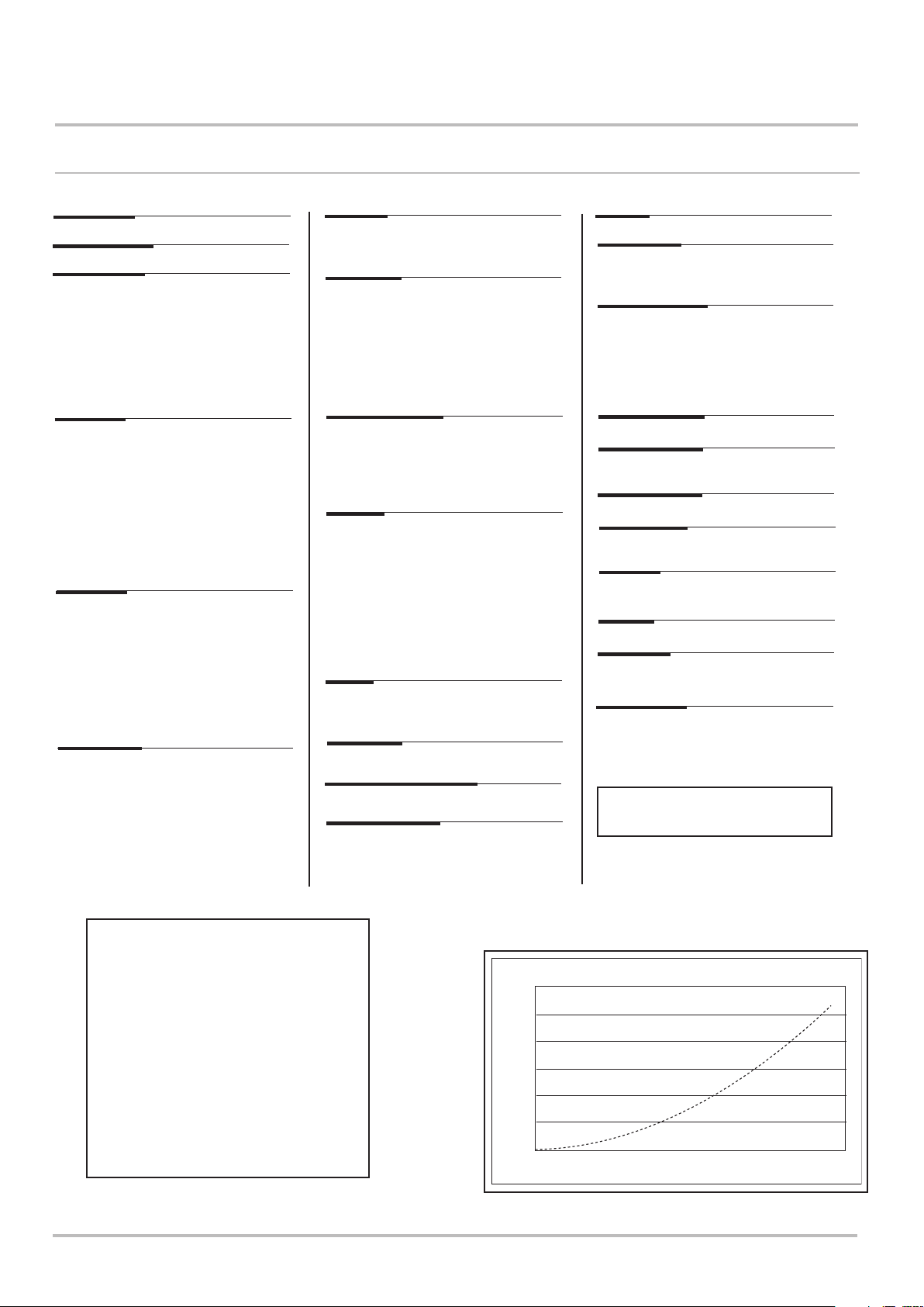
Pressure drop (mbar)
50
0
0.0 0.2 0.4 0.6 0.8 1.0 1.2 1.4 1.6 1.8
Pressure drop vs Flow
3
hr)
Flow (m

7684226-01 (06/17) EcoBlue Heat 15
Technical Specification 3
3.2 Technical Parameters
See
Technical parameters for boiler space heaters
Baxi EcoBlue Heat ErP
Condensing boiler
Low-temperature boiler
(1)
B1 boiler
Cogeneration space heater
Combination heater
Rated heat output
Useful heat output at rated heat output
Prated
P
4
kW
kW
and high temperature regime
Useful heat output at 30% of rated heat
output and low temperature regime
(1)
Seasonal space heating energy efficiency
Useful efficiency at rated heat output and
high temperature regime
(2)
Useful efficiency at 30% of rated heat
output and low temperature regime
(1)
P
1
Š
s
Š
4
Š
1
kW
%
%
%
Auxiliary electricity consumption
Full load
Part load
Standby mode
elmax
elmin
P
SB
kW
kW
kW
Other items
Standby heat loss
Ignition burner power consumption
Annual energy consumption
P
stby
P
ign
Q
HE
kW
kW
kWh
GJ
Sound power level, indoors
Emissions of nitrogen oxides
(1) Low temperature means for condensing boilers 30°C, for low temperature boilers 37°C and for other heaters 50°C return temperature (at
heater inlet).
(2) High temperature regime means 60°C return temperature at heater inlet and 80°C feed temperature at heater outlet.
L
WA
NO
X
dB
mg/kWh
12 15 18 21
Yes Yes Yes Yes Yes
No No No No No
No No No No No
No No No No No
No No No No No
13 16 19 21 25
13.0 16.0 19.0 21.0 25.0
4.3 5.4 6.4 7.0 8.4
93 93 93 93 93
88.0 87.9 87.8 87.8 87.7
98.0 98.0 98.0 98.0 98.0
0.017 0.020 0.023 0.025 0.033
0.014 0.014 0.014 0.014 0.014
00000
0.028 0.028 0.028 0.028 0.028
-----
11183 13764 16344 18065 21506
40 50 59 65 77
32 33 34 35 37
18 20 21 23 24
24
The back cover for contact details.

16 EcoBlue Heat 7684226-01 (06/17)
3 Technical Specification
3.3 Dimensions and Connections
IMPORTANT: The 1.5° fall provided by the elbow is
to allow condensate to run back to the boiler, for
disposal through the condensate discharge pipe.
When using extensions the fall along the flue
system must be increased to 3°.
Where extensions are used ensure the clearance
above the top of the flue elbow (X) is as shown in
the table below:-
360° Orientation
Tube Ø 100mm
D
C
B
A
E
F
At Least 3°
At Least
1.5°
Flue length (Y)
up to 1m
1m - 2m
2m - 3m
3m - 4m
4m - 5m
5m - 6m
Clearance (X)
30mm
84mm
134mm
186mm
238mm
290mm
NOTE: There must be no part of the air duct
(white tube) visible outside the property after
installation. The flue seal should fit neatly and
effect a good seal.
G
X
Y
6m max
DIMENSIONS
A 625mm
B 270mm
C 370mm
D 116mm Ø Min.
E 165mm
F 155mm
G 110mm
H 550mm
For clearances see
Section 5.3.6

7684226-01 (06/17) EcoBlue Heat 17
Technical Specification 3
3.4 Electrical Diagram
Safety
Thermostat
bk
br
br
g/y
b
User Interaction
bk
Gas Valve
Controller
bk
Return
Sensor
b
13
bk
Flow
Sensor
bk
g/y
1
bk
bk
bk
r
Not used
Electrode
g/y
br
b
“Socket & See”
Electrical Test Point
Mains
Pressure Switch
(where fitted)
Key To Wiring Colours
b - Blue
r - Red
br - Brown
g/y - Green/Yellow
bk - Black
r
Parameter
bk
Loop Connector
(where no pressure
switch fitted)
Unit
FROM TO COLOUR LINK
HIGH LIMIT BLACK
1
FLOW SENSOR
2
3
FLOW SENSOR
4
FLOW SENSOR
5
6
RETURN TEMP
RETURN TEMP
7
FLOW TEMP
8
PSU
9
10
PSU
PSU
11
PSU
12
HIGH LIMIT
13
13 1
BLACK
BLACK
BLACK
BLUE
BLACK
RED
BLACK
BLACK
BLACK
BLACK
BLACK
PRESURE SWITCH
COMBI ONLY
COMBI ONLY
COMBI ONLY
FLOW TEMP
PRESURE SWITCH
23456789101112

18 EcoBlue Heat 7684226-01 (06/17)
4 Description of the Product
4 Description of the Product
4.1 General Description
1. The Baxi EcoBlue Heat Range are gas fired wall mounted
powered flue condensing boilers.
2. The maximum output of the boiler is :-
12 model - 13 kW
15 model - 16 kW
18 model - 19 kW
21 model - 21 kW
24 model - 25 kW
3. The boiler modulates automatically to the system load up to
the set output. It is designed for use on Natural Gas (G20) only.
4. The two illuminated User Interaction Controller push buttons
provide information about the operating condition of the boiler.
5. The boiler is suitable for fully pumped open vented central
heating and domestic hot water systems and sealed systems.
6. An information label giving details of the model, serial number
and Gas Council number is situated on the front left underside of
the outercase and is accessed by pulling forward gently (Fig. 1).
7. The boiler data label is positioned on the inside lower righthand side of the boiler and can be seen when the outercase
panel is removed (Fig. 1).
8. The boiler is intended to be installed in residential/domestic
environments on a governed meter supply only.
9. The boiler must be installed with one of the purpose designed
flues such as one of the standard telescopic flue kits detailed in
the Flue Accessories & Fitting Guide.
All systems must be thoroughly cleansed, flushed and
treated with inhibitor (see Section 5.2.6).
These Installation & Servicing Instructions MUST be
read in conjunction with the Flue Accessories & Fitting Guide
supplied in the Literature Pack.
Information
Label
Slide
Forward
Fig. 1
Data Label

7684226-01 (06/17) EcoBlue Heat 19
Description of the Product 4
4.2 Operating Principle
1. Switched Live On: When the boiler switched live turns on
the boiler, a 20 second check cycle takes place. If the flow
temperature is less than the boiler set-point temperature the
ignition cycle will start. Pre-purge, Ignition and Burner on.
2. Fan Pre-Purge: The boiler has a 10 second pre-purge (Fan
On, Spark Generator and Gas Valve off) before the start of the
ignition sequence.
3. Ignition: The boiler has a 5 second ignition period (Fan,
Spark Generator and Gas Valve on) and burner on occurs when
a flame is detected. If a flame is not detected within the 5
second ignition period then 4 more ignition attempts are made.
If a flame is not detected after the 5 ignition attempts the boiler
goes to an ignition lock-out and an error code is displayed.
4. Burner on: After a successful ignition, Burner on occurs (Fan
and Gas Valve on, Spark Generator off). The boiler flow
temperature is controlled by varying the fan speed (and thereby
the gas rate) to achieve the optimum boiler operation. If the
boiler flow temperature exceeds the boiler set-point, the burner
will turn off (Fan and Gas Valve off).
5. Overtemperature: If a boiler overtemperature event occurs
(triggering the safety thermostat) the burner shuts down (Fan off
and Gas Valve off). A locking signal is generated and an error
code is displayed.
6. Lockout: If a lock-out error is displayed (Fan, Spark
Generator and Gas Valve off) the boiler can only be reset by
manually pressing the reset button. If 5 lock-outs are reset
within a 1 hour period then boiler becomes inoperable. It is
necessary to switch off the power supply to the boiler, and when
reinstated the reset button pressed again to operate the
appliance.
Any lock-out errors that occur regularly will require further
investigation and rectification.
Baxi Customer Support: 0344 871 1545.
Mains On.
(CH or DHW demand)
Self test cycle for 20s
(output setting displayed)
NO
temperature less
than set point ?
10 second pre-purge
5 second ignition
Flame detected ?
Burner on
Modulate output
Flow
YES
YES
NO
5th ignition attempt ?
YES
Ignition Lockout
Flow temp or
rate of rise too
high ?
NO
YES
Burner Off
Mains Off
(Demand satisfied)
NO
Over Temp
Fault ?
YES
Lockout

20 EcoBlue Heat 7684226-01 (06/17)
4 Description of the Product
4.3 Main Components
1. Heat Exchanger
2. Combustion Control Unit
3. Condensate Trap
4. Exhaust Tube
5. Inlet Silencer
6. User Interaction Controller
7. Gas Cock
8. Air Pressure Switch (21 & 24 model only)
9. System Drain Cock
10. Air Vent
11. “Socket & See” Electrical Test Point
1
2
3
4
5
6
7
8
9
10
11
11. “Socket & See” Electrical Test Point
The test point enables engineers to
perform preliminary electrical checks, test
for safe isolation etc.
 Loading...