

baxi Ecoblue 12 Heat ErP, Ecoblue 15 Heat ErP, Ecoblue 18 Heat ErP, Ecoblue 21 Heat ErP, Ecoblue 24 Heat ErP User guide
Page 1

EcoBlue Heat
User Guide
United Kingdom
en
Gas Fired Wall Mounted Condensing Boiler
12 - 15 - 18 - 21 - 24
Please keep these instructions in a safe place.
If you move house please hand them over to the next occupier.
Page 2

Model Range
Baxi EcoBlue 12 Heat ErP
o
G.C.N
41 470 29
Baxi EcoBlue 15 Heat ErP
o
G.C.N
41 470 30
Baxi EcoBlue 18 Heat ErP
o
G.C.N
41 470 31
Baxi EcoBlue 21 Heat ErP
o
G.C.N
41 470 32
Baxi EcoBlue 24 Heat ErP
o
G.C.N
41 470 33
Dear Customer,
Thank you for purchasing this appliance.
Please read this manual carefully before using the product and keep it in a safe place for future reference.
In order to ensure continued safe and efficient operation we recommend that the product is regularly maintained. Our Service and
After Sales organization can assist with this.
We hope you will receive many years of satisfactory service.
ISO 9001
FM 00866
0086
© Baxi Heating UK Ltd 2016 All rights reserved. No part of this
publication may be reproduced or transmitted in any form or by any
means, or stored in any retrieval system of any nature (including in any
database), in each case whether electronic, mechanical, recording or
otherwise, without the prior written permission of the copyright owner,
except for permitted fair dealing under Copyrights, Designs and
Patents Act 1988.
Applications for the copyright owner’s permission to reproduce or
make other use of any part of this publication should be made, giving
details of the proposed use, to the following address:
The Company Secretary, Baxi Heating UK Limited,
Brooks House, Coventry Road, Warwick. CV34 4LL
Full acknowledgement of author and source must be given.
WARNING: Any person who does any unauthorised act in relation to a
copyright work may be liable to criminal prosecution and civil claims for
damages.
The Benchmark Scheme
Baxi Heating UK Ltd is a licensed member of the Benchmark Scheme
which aims to improve the standards of installation and commissioning
of domestic heating and hot water systems in the UK and to encourage
regular servicing to optimise safety, efficiency and performance.
Benchmark is managed and promoted by Heating and Hotwater
Industry Council. For more information visit www.centralheating.co.uk
2 EcoBlue Heat 7219718-03 (11/16)
Page 3

Contents
Contents
1 Introduction
1.1 General
1.2 Additional Documentation
1.3 Symbols Used
1.4 Abbreviations / Glossary
1.5 Extent of Liabilities
1.5.1 Manufacturer’s Liability
1.5.2 Installer’s Responsibility
1.5.3 User’s Responsibility
2 Safety
2.1 General Safety Instructions
2.2 Recommendations
2.2.1 Benchmark Commissioning Checklist
3 Technical Specifications
3.1 Technical Data
3.1.1 Clearances
4 Description of the Product
4.1 General Description
4.2 Operating Principle
4.2.1 In Operation
4.3 Control Panel Description
4.3.1 User Interaction Controller
4.3.2 Indicator Lights
4.4 Standard Delivery
4.5 Accessories & Options
4.5.1 Optional Extras
6
6
6
6
7
7
7
8
8
9
9
10
10
11
11
12
13
13
13
13
14
14
14
15
15
15
5 Operation
5.1 Operation Checking Procedure & Basic Fault Identification
5.2 Shutdown
5.3 Frost Protection
6 Settings
6.1 Setting the Boiler Flow Temperature
7 Maintenance
7.1 General
7.2 Maintenance Instructions
7.3 Filling the System
7.4 Venting the System
7.5 Draining the System
16
16
18
18
18
18
19
19
19
20
21
22
7219718-03 (11/16)
EcoBlue Heat
3
Page 4

Contents
8 Troubleshooting
8.1 Fault Warning & Lock-out Codes
8.2 Fault Finding
9 Decommissioning
9.1 Decommissioning Procedure
10 Disposal
10.1 Disposal / Recycling
11 Environmental
11.1 Energy Saving
11.2 Room Thermostats and Settings
12 Warranty
12.1 General
12.2 Terms of Warranty
12.2.1 Standard Warranty Terms and Conditions
13 Appendix
13.1 ErP Information
13.1.1 Product Fiche - Boiler Space Heaters
13.1.2 Package Fiche - Boilers
23
23
24
25
25
25
25
26
26
26
27
27
27
27
29
29
29
30
4 EcoBlue Heat 7219718-03 (11/16)
Page 5

This page is intentionally blank
7219718-03 (11/16) EcoBlue Heat 5
Page 6

1 Introduction
1 Introduction
1.1 General
Warning
This boiler can be used by children aged 8 years and
above and by persons with reduced physical, sensory
or mental capabilities or lack of experience and
knowledge when they have been given supervision or
instruction concerning the safe use of the device and
understand the resulting risks. Children must not be
allowed to play with the appliance. Cleaning and user
maintenance must not be carried out by children
without supervision.
WARNING
WARNING
Installation, repair and maintenance must only be
Installation, repair and maintenance must only be
carried out only by a competent person. This
carried out only by a competent person. This
document is intended for use by competent persons,
document is intended for use by competent persons,
All Gas Safe registered engineers carry an ID card with their
licence number and a photograph. You can check your engineer
is registered by telephoning 0800 408 5500 or online at
www.gassaferegister.co.uk
This manual is intended for the user of the Baxi EcoBlue Heat
boiler. If the appliance is sold or transferred, or if the owner
moves leaving the appliance behind you should ensure that the
manual is kept with the appliance for consultation by the new
owner and their installer.
The appliance is designed as a boiler for use in residential
domestic environments on a governed meter supply only. The
selection of this boiler is entirely at the owner’s risk. If the
appliance is used for purposes other than or in excess of these
specifications, the manufacturer will not accept any liability for
resulting loss, damage or injury.
1.2 Additional Documentation
1.3 Symbols Used
The manufacturer will not accept any liability whatsoever
for loss, damage or injury arising as a result of failure to
observe the instructions for use, maintenance and
installation of the appliance.
Various timers, external controls, etc. are available as optional
extras. Full details are contained in the relevant sales literature.
In these instructions, various danger levels are employed to
draw the user's attention to particular information. In so doing,
we wish to safeguard the user's safety, prevent hazards and
guarantee correct operation of the appliance.
DANGER
Risk of a dangerous situation causing serious
physical injury.
WARNING
Risk of a dangerous situation causing slight physical
injury.
CAUTION
Risk of material damage.
Signals important information .
Signals a referral to other instructions or other pages
in the instructions.
6 EcoBlue Heat 7219718-03 (11/16)
Page 7

1.4 Abbreviations / Glossary
1.5 Extent of Liabilities
Introduction 1
DHW: Domestic Hot Water
CH: Central Heating
GB: Great Britain
IE: Ireland
BS: British Standard
HHIC: Heating and Hotwater Industry Council
1.5.1. Manufacturer's Liability
Our products are manufactured in compliance with the
requirements of the various european applicable Directives.
They are therefore delivered with marking and all relevant
documentation. In the interest of customers, we are
continuously endeavouring to make improvements in product
quality. All the specifications stated in this document are
therefore subject to change without notice.
The manufacturer will not accept any liability for loss, damage or
injury arising as a result of:-
Failure to abide by the instructions on using the appliance.
Failure to regularly maintain the appliance, or faulty or
inadequate maintenance of the appliance.
Failure to abide by the instructions on installing the
appliance.
This company declares that no substances harmful to
health are contained in the appliance or used during
appliance manufacture.
The appliance is suitable only for installation in GB and IE and
should be installed in accordance with the rules in force, and
only used in a suitably ventilated location.
In GB, the installation must be carried out by a Gas Safe
Registered Installer. It must be carried out in accordance with
the current and relevant requirements of legislation and
guidance.
Where no specific instructions are given, reference should be
made to the relevant British Standard Code of Practice.
In IE, the installation must be carried out by a competent person
and installed in accordance with the current edition of I.S. 813
‘Domestic Gas Installations’, the current Building Regulations
and reference should be made to the current ETCI rules for
electrical installation.
Incorrect installation could invalidate the warranty and may lead
to prosecution.
7219718-03 (11/16) EcoBlue Heat 7
Page 8

1 Introduction
1.5.2 Installer's Responsibility
The installer is responsible for the installation and initial start up
of the appliance. The installer must adhere to the following
instructions:
Read and follow the instructions given in the manuals
provided with the appliance.
Carry out installation in compliance with the prevailing
legislation and standards.
Ensure the system is flushed and inhibitor added.
Install the flue/chimney system correctly ensuring it is
operational and complies with prevailing legislation and
standards, regardless of location of the boiler’s installation.
Only the installer should perform the initial start up and carry
out any checks necessary.
Explain the installation to the user.
Complete the Benchmark Commissioning Checklist in the
Installation Manual - this is a condition of the warranty !
Warn the user of the obligation to check the appliance and
maintain it in good working order.
Give all the instruction manuals to the user.
1.5.3. User's Responsibility
To guarantee optimum operation of the installation, you must
observe the following instructions:
Read and observe the instructions given in the manuals
supplied with the appliance.
Seek the assistance of a qualified installer for the installation
and initial commissioning.
Ask the installer to explain the installation.
Have the required annual inspection and maintenance
carried out by a qualified installer and ensure the Benchmark
Service Record in the Installation Manual is completed - this
is a condition of the warranty !
Keep the manuals in good condition and near to the
appliance.
This appliance must not be used by people with a lack of
experience or knowledge, unless they are supervised by
someone familiar with the appliance or if they have been
instructed on how to operate the appliance correctly. Do not
allow children to operate or play with the appliance.
8 EcoBlue Heat 7219718-03 (11/16)
Page 9
2 Safety
2.1 General Safety Instructions
Safety 2
DANGER
If you smell gas:
1. Turn off the gas supply at the meter
2. Open windows and doors in the hazardous area
3. Do not operate light switches
4. Do not operate any electrical equipment
5. Do not use a telephone in the hazardous area
6. Extinguish any naked flame and do not smoke
7. Warn any other occupants and vacate the
premises
8. Telephone the National Gas Emergency Service
on:- 0800 111 999
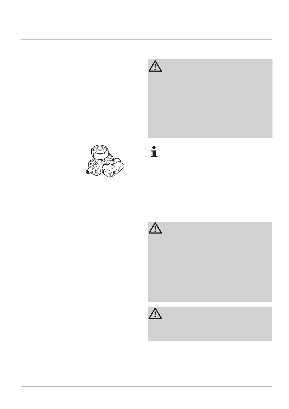
The boiler can be isolated at the gas valve under the
appliance by turning the tap through 90° (
For advice please contact your Installer, Annual
Service Provider or Baxi Customer Support - The
Service Division of Baxi. You can contact Baxi
Customer Support on telephone number 0344 871 1545.
When contacting Baxi Customer Support it will be useful
to have the ‘Benchmark Checklist’ at the back of the
Installation & Service Manual to hand as it includes details
relevant to the boiler and installation.
WARNING
Do not touch flue/chimney pipes. Depending on the
settings of the appliance, the temperature of
flue/chimney pipes may exceed 60 °C.
Do not touch radiators for long periods. Depending on
the settings of the appliance, the temperature of
radiators may reach 85 °C.
Take precautions with domestic hot water. Depending
on the settings of the appliance, domestic hot water
temperature may reach 65 °C.
1
/4turn).
CAUTION
Do not neglect to service the appliance. Contact a
qualified professional or take out a maintenance
contract for the annual servicing of the appliance.
7219718-03 (11/16) EcoBlue Heat 9
Page 10
2 Safety
2.2 Recommendations
CAUTION
Only qualified professionals are authorised to work
on the appliance and the installation.
For sealed systems regularly check the water
pressure in the system (recommended pressure is
1.5 bar). Your installer will advise on the method of
repressurising if required.
Keep the appliance accessible at all times.
Do not remove or cover the serial number label
affixed to the slide-out flap at the boiler lower left.
It must remain legible throughout the
lifetime of the appliance.
2.2.1 Benchmark Commissioning Checklist
1. Please ensure that the installer has fully completed the
Benchmark Checklist on the inside back pages of the installation
instructions supplied with the product and that you have signed it
to say that you have received a full and clear explanation of its
operation. The installer is legally required to complete a
commissioning checklist as a means of complying with the
appropriate Building Regulations (England and Wales).
2. All installations must be notified, by the installer, to Local Area
Building Control either directly or through a Competent Persons
Scheme. A Building Regulations Compliance Certificate will then
be issued to the customer who should, on receipt, write the
Notification Number on the Benchmark Checklist.
3. This product should be serviced annually to optimise its
safety, efficiency and performance. The service engineer should
complete the relevant section of the Benchmark Service Record
in the Installation & Service manual after each service.
4. The completed Benchmark Checklist & proof of annual
servicing (where applicable) will be required in the event of any
warranty work.
See Section 12 for warranty information.
10 EcoBlue Heat 7219718-03 (11/16)
Page 11

3 Technical Specifications
3.1 Technical Data
Technical Specifications 3
NOTE: All data in this section are nominal
values and subject to normal production
tolerances.
Flow Temperature (adjustable)
30° C to 80° C (± 5° C)
Outercase Dimensions
Overall Height
Casing Height - 625mm
Casing Width - 370mm
Casing Depth - 280mm
Clearances
Both Sides 5mm Min
Above Casing
Above Casing
Below Casing
Below Casing 120mm Min
Front (For Servicing) 500mm Min
Front (In Operation) 5mm Min
Ventilation of Compartment
Where the boiler is installed in a cupboard
or compartment, no air vents are required
for cooling purposes providing that the
minimum dimensions above are maintained.
Inc Flue Elbow - 790mm
(Top Flue) 190mm Min
(Rear Flue) 35mm Min
(in Cupboard) 35mm Min
Electrical Supply 230V~ 50Hz
(Appliance must be connected to an
earthed supply)
Power Consumption
12 model 17W
15 model 20W
18 model 23W
21 model 25W
24 model 33W
External Fuse Rating 3A
7219718-03 (11/16) EcoBlue Heat 11
Page 12

3 Technical Specifications
3.1.1. Clearances
1. A flat vertical area is required for the installation of the boiler.
2. These dimensions include the necessary clearances around
the boiler for case removal, spanner access and air movement
(Figs. 1 & 2). Additional clearances may be required for the
passage of pipes around local obstructions such as joists
running parallel to the front face of the boiler.
At least
1.5°
Fig. 1
270mm
500mm Min
For Servicing
Purposes
5mm Min
In Operation
5mm Min
370mm
5mm Min
190 mm
625mm
35mm Min
in Cupboard
120mm Min
Fig. 2
12 EcoBlue Heat 7219718-03 (11/16)
Page 13

4 Description of the Product
4.1 General Description
Description of the Product 4
1. The Baxi EcoBlue Heat is a wall mounted condensing boiler
which is room sealed and fan assisted, and will serve central
heating and stored domestic hot water
2. The boiler will be one of the following outputs:-
12 kW
15 kW
18 kW
21 kW
24 kW
Information
Label
Slide
Forward
4.2 Operating Principle
3. The boiler is factory set for use only on Natural Gas (G20).
4. The boiler model, serial number and Gas Council number are
shown on the information label under the boiler (Fig. 3). This is
for user reference.
Fig. 3
4.2.1 In Operation
1. Whilst the boiler is in operation cooled flue gases are
discharged through the flue gas discharge pipe. This may
appear as a cloud of steam which is normal.
2. Condensed water is discharged from the boiler heat
exchanger into a pipe (the condensate drain). This pipe must
never be altered or re-routed except by a qualified professional.
7219718-03 (11/16) EcoBlue Heat 13
Page 14

4 Description of the Product
4.3 Control Panel Description
4.3.1 User Interaction Controller (Fig. 4)
Key to symbols:-
Heating Water Temperature
Sweep Key and Status Signals
Reset button and On/Off Signal
1. The User Interaction Controller has 2 illuminating push
buttons which provide information about the operating condition
of the boiler.
2. The RESET button illuminates green when the boiler receives
a demand for CH or DHW.
Fig. 4
Fig. 5
Normal Operation - The green light remains on for
around seven seconds and then extinguishes briefly,
repeating the sequence whilst the boiler is operating.
3. The button can flash orange, green or red and at
different frequencies.
4. The User Interaction Controller also has one rotary knob. The
rotary knob is used to set the maximum flow
temperature of the heating water.
5. The temperature selected by the rotary knob must be set to a
higher temperature than the cylinder thermostat to achieve the
required hot water demand.
4.3.2 Indicator Lights (Fig. 5)
The colour of the status light on the boiler control panel and
the number of times that it flashes indicates whether the boiler is
working normally, has a problem or requires servicing.
See Section 8.1. for details of the fault conditions.
Boiler Operating The light will flash orange at EVERY
heating demand. The number of flashes will correspond with the
heat output of the boiler. This is normal and does not indicate a
fault condition. During normal running illuminates green and
blinks off momentarily every seven seconds approximately to
show the boiler is running normally and supplying heat (Fig. 6).
Error When flashing green light indicates that the boiler has
detected a problem, and is attempting to resolve it. If it does not
succeed the boiler will go into fault mode and display a red light.
The symbol indicates the Status Light ON.
Defect When flashing red light indicates that the boiler has a
fault. Press the RESET button for a minimum of 5 seconds to try
LED
LED
OFF
Fig. 6
ON
Light ON (approx. 7 sec.)
1 flash OFF
Upper Horizontal Line = Light ON
Lower Horizontal Line = Light OFF
Time
1 flash OFF
Time
and clear the fault condition.
A lock-out condition can be re-set up to 5 times within one hour
using the reset button. Any fault that occurs repeatedly should be
fully investigated and appropriate remedial actions taken by your
installer or Baxi Customer Support.
If there is a continuous red light, contact your installer or Baxi
Customer Support
The lights will be OFF when there is no demand for heat.
14 EcoBlue Heat 7219718-03 (11/16)
Page 15

4.4 Standard Delivery
4.5 Accessories & Options
Description of the Product 4
1. The literature pack contains:
Literature pack
• Installation & Servicing Manual
• User Guide Instructions
• Flue Accessories & Fitting Guide
• Warranty Documentation
• System Additives Leaflets
• Wall Template
• Product Leaflet
• Package Leaflet
(including ‘Benchmark’)
4.5.1 Optional Extras
1. Various items are available as optional extras.
Flue Accessories (elbows, extensions, clamps etc.)
(refer to the Flue Accessories & Fitting Guide supplied
in the literature pack.)
Remote relief valve kit
1M Condensate Drain Pipe ‘Trace Heating’ Element
2M Condensate Drain Pipe ‘Trace Heating’ Element
3M Condensate Drain Pipe ‘Trace Heating’ Element
5M Condensate Drain Pipe ‘Trace Heating’ Element
Any of the above MUST be fitted ONLY by a qualified competent
person. Further details can be found in the relevant sales
literature and at www.baxi.co.uk
7219718-03 (11/16) EcoBlue Heat 15
Page 16

5 Operation
5 Operation
5.1 Operation Checking Procedure & Basic Fault Identification
START
Make sure the gas
supply is turned ON
and check if other
gas appliances are
operating (e.g. fire,
cooker). If the
property has a
prepayment meter
ensure it has
sufficient credit.
NO
If no gas, consult
your supplier.
YES
Typical
examples of
external timer
Ensure timer is set for Central
Heating ON (see any instructions
Is the Timer ON and
calling for heat ?
NO
12
1
11
10
9
8
CH ON
supplied with timer)
2
3
4
5
7
6
CH OFF
YES
Is the Room Thermostat (if
fitted) set high enough ?
NO
15
20
10
5
Turn Room Thermostat to
maximum setting (typical
example shown)
5
25
15
20
10
25
NO
Press the Reset Button
Reset Button
Boiler fails to light ?
NO
CONTACT
YOUR
INSTALLER OR
SERVICE
ENGINEER.
If boiler will not
light.
16 EcoBlue Heat 7219718-03 (11/16)
Page 17

Operation 5
YES
Is there electricity to
the boiler ?
NO
Check the fused spur to
the boiler is in the on
position.
YES
If the boiler fails to
operate. Contact your
Installer.
Chimney Sweep /On
Button /Light
YES
Switch on.
NO
Reset
Button/Light
Ignition Spark will commence
YES
Boiler flame established
(Both lights are on)
YES
Boiler operating
satisfactorily.
NO
If you don’t know what you need
to do to get the boiler to light, or
need help with the system and
controls, contact your installer as
soon as possible
7219718-03 (11/16) EcoBlue Heat 17
Page 18

5 Operation / Settings
5.2 Shutdown
5.3 Frost Protection
6 Settings
1. If it is anticipated that the boiler will not be used for a long
period or the property is to be unoccupied it is recommended
that the system is drained if the electricity & gas supplies are to
be turned off. Your installer will be able to offer advice.
1. To prevent radiators and the system from freezing in rooms
where there is a risk of frost (e.g. a garage or storage room), a
frost thermostat can be connected to the system
6.1 Setting the Boiler Flow Temperature
Rotary Knob - Boiler
Temperature Adjustment
Fig. 7
+
-
To increase or decrease the boiler temperature:-
1. Turn the rotary knob to the right (Fig. 7) to increase the boiler
temperature.
2. Turn the rotary knob to the left (Fig. 7) to decrease the boiler
temperature.
3. To achieve the required domestic hot water temperature the
rotary knob must be set to a higher temperature than that selected
on the cylinder thermostat.
18 EcoBlue Heat 7219718-03 (11/16)
Page 19

7 Maintenance
7.1 General
Maintenance 7
1. The boiler does not require any special maintenance.
However, the boiler must be serviced annually in accordance
with the Installation and Service Manual and the relevant
section of the Benchmark Service Record completed in order to
maintain the warranty.
Taking out a maintenance contract is recommended.
CAUTION
Maintenance operations must be performed by a
qualified competent person.
Use only genuine spare parts.
7.2 Maintenance Instructions
2. The painted panels should be wiped with a damp cloth and
then dried completely. DO NOT USE ABRASIVE CLEANING
AGENTS.
1. The central heating system should be checked regularly.
Proceed as follows:
For Sealed Systems
If the water pressure is lower than 0.7 bar, the water
must be topped up. If necessary: top up the CH system
(recommended water pressure between 1 and 2 bar).
• Check radiators for leaks and (especially in damp areas) for
rust.
• Open and close the radiator valves several times a year to
ensure they can still be rotated.
• Only clean the outside of the boiler with a damp cloth. Do not
use abrasive cleaning agents.
CAUTION
Only a qualified installer may clean the inside of the
boiler.
7219718-03 (11/16) EcoBlue Heat 19
Page 20

7 Maintenance
7.3 Filling the System
The boiler will be installed on either an open-vented or sealed
(pressurised) heating system. If you are unsure which type of
system you have consult your installer.
Sealed systems may require periodic re-pressurisation. If this is
required on a regular basis a fault or leak is indicated. Seek
advice from your installer.
20 EcoBlue Heat 7219718-03 (11/16)
Page 21

7.4 Venting the System
1
Maintenance 7
If any air is present in the appliance or system it must be
removed in order to prevent nuisance noises that may occur
during operation. The boiler has an inbuilt auto air vent to aid
the removal of air and is supplied in the open position. Proceed
as follows:
2
10
A
1
2
3
4
system.
2. Set the room thermostat to the highest possible
temperature and any timers to ‘ON’.
3. Wait until the radiators are warm.
1. Open the valves of all the radiators connected to the
3
4. Switch off the boiler.
5. Vent the radiators. Work from the lowest radiator in the
property.
6. Open the bleed vent with the key, keeping a cloth
pressed against the vent.
7. Wait until water comes out of the bleed vent and then
4
close.
WARNING
The CH water in the radiators will still be hot.
5
C
8. Switch the boiler on.
9. After venting, if the system is of the sealed (pressurised)
type check that the water pressure is still adequate.
B
For sealed systems - if the water pressure is lower than
0.7 bar, the water must be topped up (recommended
water pressure between 1.0 and 1.5 bar when the
system is cold).
76
10. Reset the room thermostat to the desired temperature..
7219718-03 (11/16) EcoBlue Heat 21
Page 22

7 Maintenance
7.5 Draining the System
It may be necessary to drain the CH system if radiators need to
be replaced or removed, if there is a major water leak or if there
is a risk of freezing. Proceed as follows:
1
1. Open the valves of all the radiators connected to the
system.
1
2
3
4
2. Switch off or disconnect the boiler’s electrical isolation point.
3. Wait until all the radiators are cold.
4. Connect a drain hose to the lowest draining point. Place the
end of the hose in a drain or at a place where drained
water will not cause any damage.
2
3
5. Open the CH system drain valve. Drain the system.
WARNING
The CH water may still be hot.
6. When water stops flowing from the draining point, close the
draining valve.
5
See Section 7.4 Venting the system. If in doubt seek
advice from your installer.
After draining the concentration of system corrosion
inhibitor and anti-freeze may become excessively diluted seek advice from your installer.
4
22 EcoBlue Heat 7219718-03 (11/16)
Page 23

8 Troubleshooting
8.1 Fault Warning & Lock-out Codes
Troubleshooting 8
1. The colour of the status light on the boiler control panel
and the number of times that it flashes indicates whether the
boiler is working normally, has a problem or requires servicing.
Fault - Warning When flashing green light indicates that the
boiler has detected a problem, and is attempting to resolve it. If it
does not succeed the boiler will go into lock-out mode and
will display a red light.
No. of
Flashes
1
2
3
4
5
6
Green Light
Flashing
Temperature
Protection
Shutdown
Input
Flame
Loss
Communication
Fault
Parameter
Fault
Miscellaneous
Red Light
Flashing
Sensor
High Temperature
Protection
Ignition
Parameter
Miscellaneous
The symbol indicates the ashing Status Light.
LED
ON
LED
OFF
1 flash
Time
Error
Fault
Fan
Fault
Fault
1 flash
Fault - Lock-out When flashing red light indicates that the
boiler has a fault and has locked out. Press the RESET button for
a minimum of 5 seconds to try and clear the fault condition.
A lock-out condition can be re-set up to 5 times within one hour
using the reset button. Any repeating fault should be fully
investigated and appropriate remedial actions taken by your
installer or Baxi Customer Support.
If there is a continuous red light, contact your installer or Baxi
Customer Support 0344 871 1545 and inform them of the fault
code displayed.
Upper Horizontal Line = Light ON
Lower Horizontal Line = Light OFF
Time
LED
ON
LED
OFF
2 rapid flashes
Time
2 rapid flashes
Time
Normal Operation
The symbol indicates the Status Light ON.
LED
ON
LED
OFF
LED
ON
LED
OFF
LED
ON
LED
OFF
LED
ON
LED
OFF
3 rapid flashes
4 rapid flashes
5 rapid flashes
6 rapid flashes
Time
Time
Time
3 rapid flashes
4 rapid flashes
5 rapid flashes
Time
6 rapid flashes
Time
Time
Time
Time
LED
ON
LED
OFF
Light ON (approx. 7 sec.)
1 flash OFF
Time
Upper Horizontal Line = Light ON
Lower Horizontal Line = Light OFF
1 flash OFF
Time
7219718-03 (11/16) EcoBlue Heat 23
Page 24

8 Troubleshooting
8.2 Fault Finding
1. If the boiler is not working, check section 5.1 Operation Checking Procedure & Basic Fault
Identification or the fault finding table. Contact your Installer.
Problem
There is no domestic hot water
and/or the radiators are cold.
The boiler is not working.
The domestic hot water is not
hot enough.
The radiators are not hot
enough.
Possible Causes
Check that the boiler is being supplied with power
(all controls set to ON).
Check the fuses and the switches.
If possible check whether the gas cock is properly
open.
If the property has a prepayment meter ensure it
has sufficient credit.
Check if the Fault - Lock-out is illuminated. See
Section 8.1 to reset.
The boiler temperature setting is below the
cylinder thermostat setting.
The radiator valves are not open.
The temperature set point for the heating is too
low (check boiler & room thermostat).
24 EcoBlue Heat 7219718-03 (11/16)
Page 25

9 Decommissioning
9.1 Decommissioning Procedure
Decommissioning / Disposal 9 / 10
CAUTION
Only qualified professionals are authorised to
work on the appliance and system to decommission.
1. If your the boiler needs to be decommissioned either
temporarily or permanently the following should be performed:
• Switch off the boiler.
• Switch off the boiler’s electrical connection.
• Close the boiler gas valve.
• Drain the CH system.
Seek the advice of your installer.
10 Disposal
10.1 Disposal / Recycling
WARNING
Removal and disposal of the boiler must be carried
out by a qualified installer in accordance with local
and national regulations.
7219718-03 (11/16) EcoBlue Heat 25
Page 26

11 Environmental
11 Environmental
11.1 Energy Saving
Tips on saving energy:
Do not cover radiators. Do not hang curtains in front of
radiators.
Install reflective panels behind the radiators to prevent heat
losses.
Insulate the pipes in rooms that are not heated (cellars and
lofts).
Install loft insulation & double glazing.
Use draught excluders where necessary.
Upgrade any older external controls.
Turn down room thermostats by 1°C
Turn off radiators in rooms not in use.
Do not run hot (or cold) water pointlessly.
Fit a water-saving shower head to save up to 40 % energy.
Take showers rather than baths. A bath consumes twice as
much water and energy.
11.2 Room Thermostats and Settings
Various models of room thermostats are available. The
thermostat type and setting affect the total energy consumption.
A few tips:
Fully opening or closing thermostatic radiator valves result
in unwanted temperature fluctuations. Turn the thermostat knob
or valve higher or lower in small steps.
Lower the thermostat to approximately 20°C. This reduces
heating costs and energy consumption.
When rooms are to be aired, lower the thermostat well in
advance.
When setting thermostats or programmers take account of
days when nobody will be in and of holidays.
26 EcoBlue Heat 7219718-03 (11/16)
Page 27

12 Warranty
12.1 General
12.2 Terms of Warranty
Warranty 12
To make sure your boiler warranty is activated and maintained, it
is essential that the:
1. Benchmark checklist is completed by your installer
2. Warranty is registered within 30 days
3. Boiler has an annual service
Please note that failure to adhere to terms and conditions will
make your warranty invalid.
12.2.1 Standard Warranty Terms and Conditions
Warranty Registration, Service & Repair
For full terms and conditions, visit www.baxi.co.uk/terms.
Benchmark Checklist
The Benchmark Checklist will be completed by your installer and
records that the boiler has been installed and commissioned
correctly. It can be found at the back of the installation and
service manual and should be kept in a safe place for the life of
the boiler. We will check that the Benchmark Checklist has been
completed on an in-warranty visit.
Ways to register your warranty
If your boiler is eligible for an extended warranty, your installer
may register the product on your behalf and provide you with the
relevant documentation. Please check with your installer.
Should this not be the case, you can register your warranty
online at www.baxi.co.uk/registration
7219718-03 (11/16) EcoBlue Heat 27
Page 28

12 Warranty
Information
Label
Annual Service
A service must be completed every 12 months from the
date of installation to maintain your warranty.
This service must be completed by one of the following:
• A Gas Safe registered installer/engineer
• Baxi Customer Support; call us 0344 871 1545
Please make sure that your engineer has logged the service
information at the back of the installation and service manual.
You will be asked for your service history on any in-warranty
repair visit.
If you experience a problem with your boiler
For any in or out of warranty repair, Baxi Customer Support is
on hand to help you. Call our award-winning team to arrange
for one of our nationwide team of Gas Safe registered
engineers to visit.
If your product is in warranty, everything is free of charge,
subject to our warranty terms and conditions. If it is out of
warranty, we can still help and offer a range of options you can
choose from to suit your needs.
Slide
Forward
Contact Baxi Customer Support 0344 871 1545
Opening hours
Monday - Friday, 8.00am - 6.00pm
Weekends and Bank Holidays, 8.30am - 2.00pm
Please note calls may be recorded for training and monitoring
purposes.
When contacting Baxi Customer Support, please have the
following information to hand:
• Boiler serial number. This can be found on the
appliance.
• Proof of purchase if you do not have the boiler serial
number.
Please note that for in-warranty repairs, our engineers will ask
to see your service history record, completed Benchmark
Checklist and details of your installer. These can all be found in
the installation and user manual.
28 EcoBlue Heat 7219718-03 (11/16)
Page 29

Appendix 13
See
13 Appendix
13.1 ErP Information
13.1.1. Product Fiche - Boiler Space Heaters
Product fiche for boiler space heaters
Baxi EcoBlue Heat ErP 12 15 18 21 24
Seasonal space heating energy efficiency class
Rated heat output
(Prated or Psup)
Seasonal space heating energy efficiency
Annual energy consumption
Sound power level L
indoors
WA
kW
%
kWh
GJ
dB
A
13 16 19 21 25
93 93 93 93 93
11183 13764 16344 18065 21506
40 50 59 65 77
32 33 34 35 37
A A
A A
For specific precautions about assembling, installing and maintaining,
consult the relevant section as detailed on the Contents page.
7219718-03 (11/16) EcoBlue Heat 29
Page 30

13 Appendix
I
II
13.1.2. Package Fiche - Boilers
Package fiche for boilers indicating the space heating energy efficiency of the package
reliob fo ycneic fife ygrene gnitaeh ecaps lanosaeS
lortnoc erutarepmeT
utarepmet fo ehc fi morf
lortnoc er
reliob yratnemelppuS
Class IV = 2%, Class V = 3%, Class VI = 4%,
Class VII = 3.5%, Class VIII = 5%
ygrene gnitaeh ecaps lanosaeS
,%5.1 = III ssalC ,%2 = II ssalC ,%1 = I ssalC
)% ni( ycneic fife
reliob fo ehc fi morf
‘I’
1
%
2
%+
3
%( - ‘I’ ) x 0.1 = ±
noitubirtnoc raloS
ecived ralos fo ehc fi morf
)³m ni( emulov knaT )²m ni( ezis rotcelloC
%)
(1)
A* = 0.95, A = 0.91,
ni( ycneic fife rotcelloC
B = 0.86, C = 0.83,
D - G = 0.81
gnitar knaT
4
%(‘III’ x + ‘IV’ x ) x 0.9 x ( /100) x = +
59.0 esu ,A evoba si gnitar knat fI )1(
pmup taeh yratnemelppuS
pmup taeh fo ehc fi morf
)% ni( ycneic fife ygrene gnitaeh ecaps lanosaeS
5
%( - ‘I’ ) x ‘II’ = +
pmup taeh yratnemelppuS DNA noitubirtnoc raloS
eulav rellams tceles
54
6
RO
S
G F E D C B A A
<30%
egakcap fo ycneic fife ygrene gnitaeh ecaps lanosae
fo ssalc ycneic fife ygrene gnitaeh ecaps lanosaeS
egakcap
+
++
A
+++
A
7
? C°53 ta srettime taeh erutarepmet wol htiw dellatsni pmup taeh yratnemelppus dna relioB
pmup taeh fo ehc fi morf
in a building, as this effi ciency is infl uenced by further factors such as heat loss in the distribution system and the dimensioning of the
products in relation to building size and characteristics.
7
AD-3000743-01
%0.5 x 0.5 x = -
%
%+ (50 x ‘II’) =
dellatsni ecno ycneic fife ygrene lautca sti ot dnopserroc ton yam ehc fi siht ni rof dedivorp stcudorp fo egakcap eht fo ycneic fife ygrene ehT
The value of the seasonal space heating energy efficiency of the
preferential space heater, expressed in %.
The factor for weighting the heat output of preferential and supple
mentary heaters of a package as set out in the following table.
30 EcoBlue Heat 7219718-03 (11/16)
Page 31

Appendix 13
IIIIVI
V
Psup / (Prated + Psup)
(1)(2)
II, package without hot water storage tank II, package with hot water storage tank
13.1.2. Package Fiche - Boilers (cont)
The value of the mathematical expression: 294/(11 ʷ Prated),
whereby ‘Prated’ is related to the preferential space heater.
The value of the mathematical expression 115/(11 ʷ Prated),
whereby ‘Prated’ is related to the preferential space heater.
Weighting of boilers
00 0
0.1 0.3 0.37
0.2 0.55 0.70
0.3 0.75 0.85
0.4 0.85 0.94
0.5 0.95 0.98
0.6 0.98 1.00
≥ 0.7 1.00 1.00
(1) The intermediate values are calculated by linear interpolation between the two adjacent values.
(2) Prated is related to the preferential space heater or combination heater.
Package efficiency
Baxi EcoBlue Heat ErP
Temperature control X
Temperature control Y %
12 15 18 2421
%
7219718-03 (11/16) EcoBlue Heat 31
Page 32

Baxi Customer Support
0344 871 1545
Opening hours
Monday - Friday, 8.00am-6.00pm
Weekends and Bank Holidays, 8.30am-2.00pm
Please note calls may be recorded for training and monitoring purposes
baxi.co.uk
Register now to activate your warranty:
www.baxi.co.uk/registration
For the warranty to be maintained, please make sure...
1
Benchmark checklist is completed
2
Warranty is registered within 30 days
3
The boiler has an annual service
For full terms and conditions, visit www.baxi.co.uk/terms. Failure to adhere to
terms and conditions will void your manufacturer’s warranty.
Baxi
Brooks House,
Coventry Road,
Warwick, CV34 4LL
Please ensure the boiler is installed in accordance with these installation
instructions and that you adhere to the Building Regulations.
e&oe
All descriptions and illustrations provided in this document have been
carefully prepared but we reserve the right to make changes and
improvements in our products which may affect the accuracy of the
information contained in this leaflet. All goods are sold subject to our
standard Conditions of Sale which are available on request.
7219718 - 03 (11/16)
0086
 Loading...